EP1512581B1 - A vehicle seat - Google Patents
A vehicle seat Download PDFInfo
- Publication number
- EP1512581B1 EP1512581B1 EP03255568A EP03255568A EP1512581B1 EP 1512581 B1 EP1512581 B1 EP 1512581B1 EP 03255568 A EP03255568 A EP 03255568A EP 03255568 A EP03255568 A EP 03255568A EP 1512581 B1 EP1512581 B1 EP 1512581B1
- Authority
- EP
- European Patent Office
- Prior art keywords
- squab
- seat
- edge
- inner part
- outer part
- Prior art date
- Legal status (The legal status is an assumption and is not a legal conclusion. Google has not performed a legal analysis and makes no representation as to the accuracy of the status listed.)
- Expired - Lifetime
Links
Images



Classifications
-
- B—PERFORMING OPERATIONS; TRANSPORTING
- B60—VEHICLES IN GENERAL
- B60N—SEATS SPECIALLY ADAPTED FOR VEHICLES; VEHICLE PASSENGER ACCOMMODATION NOT OTHERWISE PROVIDED FOR
- B60N2/00—Seats specially adapted for vehicles; Arrangement or mounting of seats in vehicles
- B60N2/02—Seats specially adapted for vehicles; Arrangement or mounting of seats in vehicles the seat or part thereof being movable, e.g. adjustable
- B60N2/04—Seats specially adapted for vehicles; Arrangement or mounting of seats in vehicles the seat or part thereof being movable, e.g. adjustable the whole seat being movable
- B60N2/16—Seats specially adapted for vehicles; Arrangement or mounting of seats in vehicles the seat or part thereof being movable, e.g. adjustable the whole seat being movable height-adjustable
- B60N2/1605—Seats specially adapted for vehicles; Arrangement or mounting of seats in vehicles the seat or part thereof being movable, e.g. adjustable the whole seat being movable height-adjustable characterised by the cinematic
-
- B—PERFORMING OPERATIONS; TRANSPORTING
- B60—VEHICLES IN GENERAL
- B60N—SEATS SPECIALLY ADAPTED FOR VEHICLES; VEHICLE PASSENGER ACCOMMODATION NOT OTHERWISE PROVIDED FOR
- B60N2/00—Seats specially adapted for vehicles; Arrangement or mounting of seats in vehicles
- B60N2/02—Seats specially adapted for vehicles; Arrangement or mounting of seats in vehicles the seat or part thereof being movable, e.g. adjustable
- B60N2/04—Seats specially adapted for vehicles; Arrangement or mounting of seats in vehicles the seat or part thereof being movable, e.g. adjustable the whole seat being movable
- B60N2/16—Seats specially adapted for vehicles; Arrangement or mounting of seats in vehicles the seat or part thereof being movable, e.g. adjustable the whole seat being movable height-adjustable
- B60N2/1605—Seats specially adapted for vehicles; Arrangement or mounting of seats in vehicles the seat or part thereof being movable, e.g. adjustable the whole seat being movable height-adjustable characterised by the cinematic
- B60N2/161—Rods
- B60N2/1615—Parallelogram-like structure
-
- B—PERFORMING OPERATIONS; TRANSPORTING
- B60—VEHICLES IN GENERAL
- B60N—SEATS SPECIALLY ADAPTED FOR VEHICLES; VEHICLE PASSENGER ACCOMMODATION NOT OTHERWISE PROVIDED FOR
- B60N2/00—Seats specially adapted for vehicles; Arrangement or mounting of seats in vehicles
- B60N2/02—Seats specially adapted for vehicles; Arrangement or mounting of seats in vehicles the seat or part thereof being movable, e.g. adjustable
- B60N2/04—Seats specially adapted for vehicles; Arrangement or mounting of seats in vehicles the seat or part thereof being movable, e.g. adjustable the whole seat being movable
- B60N2/16—Seats specially adapted for vehicles; Arrangement or mounting of seats in vehicles the seat or part thereof being movable, e.g. adjustable the whole seat being movable height-adjustable
- B60N2/1605—Seats specially adapted for vehicles; Arrangement or mounting of seats in vehicles the seat or part thereof being movable, e.g. adjustable the whole seat being movable height-adjustable characterised by the cinematic
- B60N2/1625—Combination of rods and slides
-
- B—PERFORMING OPERATIONS; TRANSPORTING
- B60—VEHICLES IN GENERAL
- B60N—SEATS SPECIALLY ADAPTED FOR VEHICLES; VEHICLE PASSENGER ACCOMMODATION NOT OTHERWISE PROVIDED FOR
- B60N2/00—Seats specially adapted for vehicles; Arrangement or mounting of seats in vehicles
- B60N2/90—Details or parts not otherwise provided for
- B60N2/986—Side-rests
- B60N2/99—Side-rests adjustable
-
- B—PERFORMING OPERATIONS; TRANSPORTING
- B60—VEHICLES IN GENERAL
- B60R—VEHICLES, VEHICLE FITTINGS, OR VEHICLE PARTS, NOT OTHERWISE PROVIDED FOR
- B60R7/00—Stowing or holding appliances inside vehicle primarily intended for personal property smaller than suit-cases, e.g. travelling articles, or maps
- B60R7/04—Stowing or holding appliances inside vehicle primarily intended for personal property smaller than suit-cases, e.g. travelling articles, or maps in driver or passenger space, e.g. using racks
- B60R7/043—Stowing or holding appliances inside vehicle primarily intended for personal property smaller than suit-cases, e.g. travelling articles, or maps in driver or passenger space, e.g. using racks mounted on or under a seat
-
- B—PERFORMING OPERATIONS; TRANSPORTING
- B60—VEHICLES IN GENERAL
- B60N—SEATS SPECIALLY ADAPTED FOR VEHICLES; VEHICLE PASSENGER ACCOMMODATION NOT OTHERWISE PROVIDED FOR
- B60N2205/00—General mechanical or structural details
- B60N2205/30—Seat or seat parts characterised by comprising plural parts or pieces
Definitions
- This invention relates to vehicle seats.
- vehicle seats In particular it relates to a vehicle seat which retains items placed on the seat while the vehicle is in motion (sse, for example, DE 197 35 098 A , corresponding to the preamble of claim 1).
- the edge may be raised relative to squab.
- the edge may be up to 50mm higher than the squab in its displaced position.
- friction retains the edge and squab in their relative positions.
- the outer part of the squab may be hinged at the back of the seat relative to the inner part, such that the outer part may be raised relative to the inner part to form a lip which extends across the front and sides of the inner part.
- the outer part of the squab may move by means of a linkage mechanism such that the outer part is raised relative to the inner part to form a lip of substantially even height extending across the front and sides of the inner part of the squab.
- a conventional car seat 1 comprises a squab 3 for sitting on, a back 5 and a headrest 7 as shown in Fig. 1 .
- Such seats are conventionally mounted within a vehicle such that an occupant faces in the direction of travel with the squab 3 being forward of the seat back 5 in relation to the usual direction of motion of the vehicle.
- the terms 'front' and 'back' are used herein to indicate forward and rearward positions respectively on a conventionally mounted seat in relation to the usual direction of motion.
- the seat shown in Figs. 1 and 2 further comprises a two-part squab having an inner part 3 and an edge or outer part 9.
- the inner part 3 is static and mounted on a seat pan (not shown) as per a conventional car seat.
- the outer part 9 is mounted on a separate seat pan which is hinged at its back edge. This enables the front edge of the outer part 9 to be raised by lifting the outer part 9 at its front edge relative to the hinged back edge and the inner part 3, to form a raised wall or lip 13 which extends partially round the inner part 3 of the squab across the front and sides as shown in Fig. 2 .
- the front edge of the outer part may be raised to form a lip 13 approximately 50mm in height relative to the inner part 3 at its front edge. Friction between the inner and outer parts retains the outer part in its raised position until such time as it is pushed down again.
- the driver may deposit any personal items he/she wishes to be easily accessible during or at the end of the journey on the passenger seat squab. He/she then lifts the outer part 9 of the squab at its front edge as indicated by arrow 11 to form a raised wall or lip 13 which extends across the front and sides of the inner part 3 of the squab and surrounds the deposited items. The driver may then embark on his/her journey. Tests have shown that a lip of up to 50mm in height relative to the inner part 3 of the squab is sufficient to prevent personal items placed on the seat from falling into the passenger footwell or into the gaps either side of the seat during firm braking and cornering.
- any items placed on the seat may be removed and the outer part 9 of the squab simply pushed back down to its lowered position, either by hand or by the action of the passenger sitting on the seat.
- the outer part of the squab may be raised relative to the static inner part, it will be clear that as an alternative the inner part of the squab could be lowered relative to a static outer part, or indeed both parts could be movable to create the wall round the squab.
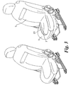
- an alternative not forming part of the present invention might include a linkage mechanism which enables the edge to be raised at the back of the seat as well as the front. This would have the advantage of providing a raised lip of substantially even height round the inner part of the squab, as shown in Fig. 3 .
- a linkage mechanism is shown in more detail in Figs. 4a and 4b , and comprises four parallel linkages, two on either side of the seat towards its front and back (only one side of the seat is shown in the figures). Each linkage comprises a primary strut 15 and a secondary strut 16.
- the primary strut 15 is hinged at its upper end 19 to the outer part 9 of the squab while its lower end 17 is free to slide back and forth along a rail 18.
- the secondary strut 16 is hinged at its lower end 20 at a position just in front of the rail 18, and at its upper end to a mid-point along the primary strut 15.
- the inner part 3 of the squab is statically attached to the seat base (not shown).
- Fig. 4a shows the outer part 9 of the squab in a lowered position suitable for occupancy by a passenger.
- the outer part 9 of the squab may be raised by lifting it such that the secondary struts 16 pivot about their lower hinges 20 while the lower ends 17 of the primary struts 15 slide forward in rails 18, and the upper ends 19 of the primary struts 15 move straight up as indicated by arrows 21 in the detailed view of the linkage shown in Fig. 4b , until it reaches its raised position as shown in Fig. 4b , while the inner part 3 of the squab remains unmoved.
- the outer part 9 of the squab In its raised position, the outer part 9 of the squab forms a raised lip 23 of substantially even height surrounding sides and front of the inner part 3 of the squab to prevent personal items placed on the seat from falling into the passenger footwell or into the gaps either side of the seat during firm braking and cornering.
- the outer part 9 of the squab may be lowered simply by pushing it downwards such that it returns to its lowered position.
- a simple ratchet mechanism underneath the squab may be used to prevent the parts from moving under the influence of vibrations.
- a spring-loaded mechanism with a catch and release button may be used to raise/lower and retain the outer or inner parts in this position.
- a further alternative would be to operate the outer or inner part of the squab electrically by means of a motor, switch and appropriate gearing in the same way as other electric seat adjustments are made. If the outer part of the squab were operated in this way, the gearing could include a slip device to allow for the outer part of the squab to be pushed down so as not to require powering down before it could be sat on.
Landscapes
- Engineering & Computer Science (AREA)
- Mechanical Engineering (AREA)
- Aviation & Aerospace Engineering (AREA)
- Transportation (AREA)
- Seats For Vehicles (AREA)
Description
- This invention relates to vehicle seats. In particular it relates to a vehicle seat which retains items placed on the seat while the vehicle is in motion (sse, for example,
DE 197 35 098 A , corresponding to the preamble of claim 1). - Many car drivers tend to 'dump' loose personal items on the front passenger seat when there is no passenger present, rather than stow them in specific storage areas like the glovebox. Such items typically include anything the driver wishes to be easily accessible during or at the end of the journey, such as wallets, mobile phones, CDs, MP3 players, small bags, food, cigarettes, PDAs, work documents etc. Although this is convenient, such loose items tend to fall off the seat during firm braking or cornering, with the result that the items are no longer easily accessible. This can (i) be inconvenient for the driver when he/she wishes to access the items, (ii) be dangerous should the driver try to access such items while driving the vehicle, and (iii) cause damage to sensitive or fragile items.
- Seats with storage compartments underneath the squab are known. These may be accessed by means of tilting, flipping or removable squabs. However, such compartments do not allow ready access to items stored therein while driving, and there remains a need for a means for retaining loose items placed on a seat.
- According to the present invention, there is provided a vehicle seat having the features set forth in claim 1.
- Further features of the invention are disclosed in the dependent claims.
- Preferably, the edge may be raised relative to squab.
- Preferably, the edge may be up to 50mm higher than the squab in its displaced position.
- Suitably, friction retains the edge and squab in their relative positions.
- According to the invention, the outer part of the squab may be hinged at the back of the seat relative to the inner part, such that the outer part may be raised relative to the inner part to form a lip which extends across the front and sides of the inner part. In an alternative not forming part of the present invention, the outer part of the squab may move by means of a linkage mechanism such that the outer part is raised relative to the inner part to form a lip of substantially even height extending across the front and sides of the inner part of the squab.
- The invention will now be further described, by way of example, with reference to the accompanying drawings, in which:
-
Figure 1 is a perspective view of a seat in accordance with the invention having its edge in an undisplaced position relative to the squab; -
Figure 2 is a perspective view of the seat shown inFig. 1 having its edge in a displaced position relative to the squab; -
Figure 3 is a perspective view of the above-mentioned alternative not forming part of the present invention; and -
Figures 4a and 4b are schematic views of the hinge arrangement used in the seat shown inFig. 3 . - A conventional car seat 1 comprises a
squab 3 for sitting on, aback 5 and aheadrest 7 as shown inFig. 1 . Such seats are conventionally mounted within a vehicle such that an occupant faces in the direction of travel with thesquab 3 being forward of theseat back 5 in relation to the usual direction of motion of the vehicle. The terms 'front' and 'back' are used herein to indicate forward and rearward positions respectively on a conventionally mounted seat in relation to the usual direction of motion. - In addition to the features of a conventional seat, the seat shown in
Figs. 1 and2 further comprises a two-part squab having aninner part 3 and an edge orouter part 9. Theinner part 3 is static and mounted on a seat pan (not shown) as per a conventional car seat. Theouter part 9 is mounted on a separate seat pan which is hinged at its back edge. This enables the front edge of theouter part 9 to be raised by lifting theouter part 9 at its front edge relative to the hinged back edge and theinner part 3, to form a raised wall orlip 13 which extends partially round theinner part 3 of the squab across the front and sides as shown inFig. 2 . The front edge of the outer part may be raised to form alip 13 approximately 50mm in height relative to theinner part 3 at its front edge. Friction between the inner and outer parts retains the outer part in its raised position until such time as it is pushed down again. - If the seat is not to be used by a passenger for a journey, the driver may deposit any personal items he/she wishes to be easily accessible during or at the end of the journey on the passenger seat squab. He/she then lifts the
outer part 9 of the squab at its front edge as indicated by arrow 11 to form a raised wall orlip 13 which extends across the front and sides of theinner part 3 of the squab and surrounds the deposited items. The driver may then embark on his/her journey. Tests have shown that a lip of up to 50mm in height relative to theinner part 3 of the squab is sufficient to prevent personal items placed on the seat from falling into the passenger footwell or into the gaps either side of the seat during firm braking and cornering. - Should a passenger wish to use the seat, any items placed on the seat may be removed and the
outer part 9 of the squab simply pushed back down to its lowered position, either by hand or by the action of the passenger sitting on the seat. - Although in the seat described herein, the outer part of the squab may be raised relative to the static inner part, it will be clear that as an alternative the inner part of the squab could be lowered relative to a static outer part, or indeed both parts could be movable to create the wall round the squab.
- It will also be clear that instead of a hinge arrangement for the outer part of the squab just at the back of the seat, an alternative not forming part of the present invention might include a linkage mechanism which enables the edge to be raised at the back of the seat as well as the front. This would have the advantage of providing a raised lip of substantially even height round the inner part of the squab, as shown in
Fig. 3 . Such a linkage mechanism is shown in more detail inFigs. 4a and 4b , and comprises four parallel linkages, two on either side of the seat towards its front and back (only one side of the seat is shown in the figures). Each linkage comprises aprimary strut 15 and asecondary strut 16. Theprimary strut 15 is hinged at itsupper end 19 to theouter part 9 of the squab while itslower end 17 is free to slide back and forth along arail 18. Thesecondary strut 16 is hinged at itslower end 20 at a position just in front of therail 18, and at its upper end to a mid-point along theprimary strut 15. Theinner part 3 of the squab is statically attached to the seat base (not shown).Fig. 4a shows theouter part 9 of the squab in a lowered position suitable for occupancy by a passenger. - If the seat is not to be used by a passenger, the
outer part 9 of the squab may be raised by lifting it such that thesecondary struts 16 pivot about theirlower hinges 20 while thelower ends 17 of theprimary struts 15 slide forward inrails 18, and theupper ends 19 of theprimary struts 15 move straight up as indicated byarrows 21 in the detailed view of the linkage shown inFig. 4b , until it reaches its raised position as shown inFig. 4b , while theinner part 3 of the squab remains unmoved. In its raised position, theouter part 9 of the squab forms a raisedlip 23 of substantially even height surrounding sides and front of theinner part 3 of the squab to prevent personal items placed on the seat from falling into the passenger footwell or into the gaps either side of the seat during firm braking and cornering. - The
outer part 9 of the squab may be lowered simply by pushing it downwards such that it returns to its lowered position. - Instead of friction between the inner and outer parts of the squab to retain the respective parts in their displaced positions, it will be clear that alternative mechanisms may be used. For example, a simple ratchet mechanism underneath the squab may be used to prevent the parts from moving under the influence of vibrations. Alternatively, a spring-loaded mechanism with a catch and release button may be used to raise/lower and retain the outer or inner parts in this position. A further alternative would be to operate the outer or inner part of the squab electrically by means of a motor, switch and appropriate gearing in the same way as other electric seat adjustments are made. If the outer part of the squab were operated in this way, the gearing could include a slip device to allow for the outer part of the squab to be pushed down so as not to require powering down before it could be sat on.
Claims (6)
- A vehicle seat (1) comprising a squab (3) for sitting on, the seat (1) further comprising an edge (9), the squab (3) and/or edge (9) being movable relative to each other between a first position in which the edge is not substantially higher than the squab and a second position in which the edge (9) is higher than the squab such that the edge (9) forms a wall at least partially round the upper surface of the squab (3) to retain items placed on the seat (1) while the vehicle is in motion, characterised in that the squab (3) is a two-part squab having an outer part (9) and an inner part (3), the outer part (9) forming the edge and being hinged at the back of the seat relative to the inner part (3), such that the outer part (9) may be raised relative to the inner part (3) to form a lip (13) which extends across the front and sides of the inner part (3).
- A vehicle seat (1) according to claim 1, characterised in that the edge (9) may be raised relative to squab (3).
- A vehicle seat (1) according to claim 1 or 2, characterised in that, when displaced, the edge (9) may be up to 50mm higher than the squab (3).
- A vehicle seat (1) according to any preceding claim, characterised in that friction retains the edge (9) and squab (3) in their relative positions.
- A vehicle seat (1) according to any one of claims 1 to 3, wherein the edge (9) and squab (3) are relatively movable by means of a ratchet, a spring-loaded, or electric mechanism.
- A car comprising a seat according to any preceding claim.
Priority Applications (2)
| Application Number | Priority Date | Filing Date | Title |
|---|---|---|---|
| EP03255568A EP1512581B1 (en) | 2003-09-06 | 2003-09-06 | A vehicle seat |
| DE60326840T DE60326840D1 (en) | 2003-09-06 | 2003-09-06 | vehicle seat |
Applications Claiming Priority (1)
| Application Number | Priority Date | Filing Date | Title |
|---|---|---|---|
| EP03255568A EP1512581B1 (en) | 2003-09-06 | 2003-09-06 | A vehicle seat |
Publications (2)
| Publication Number | Publication Date |
|---|---|
| EP1512581A1 EP1512581A1 (en) | 2005-03-09 |
| EP1512581B1 true EP1512581B1 (en) | 2009-03-25 |
Family
ID=34130345
Family Applications (1)
| Application Number | Title | Priority Date | Filing Date |
|---|---|---|---|
| EP03255568A Expired - Lifetime EP1512581B1 (en) | 2003-09-06 | 2003-09-06 | A vehicle seat |
Country Status (2)
| Country | Link |
|---|---|
| EP (1) | EP1512581B1 (en) |
| DE (1) | DE60326840D1 (en) |
Families Citing this family (2)
| Publication number | Priority date | Publication date | Assignee | Title |
|---|---|---|---|---|
| FR2920359B1 (en) * | 2007-08-31 | 2009-11-06 | Peugeot Citroen Automobiles Sa | STORAGE BIN FOR REMOVABLE REAR SEAT |
| JP6533564B2 (en) * | 2017-10-24 | 2019-06-19 | 本田技研工業株式会社 | Headrest storage structure |
Citations (1)
| Publication number | Priority date | Publication date | Assignee | Title |
|---|---|---|---|---|
| US6161896A (en) * | 1999-10-13 | 2000-12-19 | Daimlerchrysler Corporation | Automotive vehicle rear seat storage system |
Family Cites Families (8)
| Publication number | Priority date | Publication date | Assignee | Title |
|---|---|---|---|---|
| US3309135A (en) * | 1964-10-28 | 1967-03-14 | Jannetto John | Package retaining rack apparatus |
| JPH07277082A (en) * | 1994-04-14 | 1995-10-24 | Araco Corp | Vehicle seat |
| DE9412066U1 (en) * | 1994-07-26 | 1994-09-22 | Bechthold, Werner, 67487 St Martin | Device for the safe depositing of objects on motor vehicle seats |
| JPH09150679A (en) * | 1995-11-29 | 1997-06-10 | Kanto Auto Works Ltd | Car seat tray and baggage holder |
| JPH1035364A (en) * | 1996-07-24 | 1998-02-10 | Showa Aircraft Ind Co Ltd | Passenger seat with book holder |
| DE19735098C2 (en) * | 1997-08-13 | 2000-03-23 | Hillebrand Jun | Seat for a vehicle |
| US5908218A (en) * | 1998-01-13 | 1999-06-01 | Martin; Steve | Devices for restricting the movements of objects |
| FR2783217B1 (en) * | 1998-09-10 | 2000-10-13 | Peugeot | STORAGE DEVICE INTEGRATED IN A MOTOR VEHICLE SEAT |
-
2003
- 2003-09-06 DE DE60326840T patent/DE60326840D1/en not_active Expired - Lifetime
- 2003-09-06 EP EP03255568A patent/EP1512581B1/en not_active Expired - Lifetime
Patent Citations (1)
| Publication number | Priority date | Publication date | Assignee | Title |
|---|---|---|---|---|
| US6161896A (en) * | 1999-10-13 | 2000-12-19 | Daimlerchrysler Corporation | Automotive vehicle rear seat storage system |
Also Published As
| Publication number | Publication date |
|---|---|
| DE60326840D1 (en) | 2009-05-07 |
| EP1512581A1 (en) | 2005-03-09 |
Similar Documents
| Publication | Publication Date | Title |
|---|---|---|
| JP3768467B2 (en) | Vehicle seat structure | |
| US7445261B2 (en) | Console assembly for a vehicle | |
| EP1894786A2 (en) | Dual sliding center console | |
| US6921118B2 (en) | Sliding and nesting console system | |
| US6547326B1 (en) | Automotive seat flip-out cupholder | |
| EP1449710B1 (en) | Seat device including a stowable auxiliary seat | |
| US7784843B2 (en) | Vehicle console with sliding panel | |
| CN107054176B (en) | Vehicle seat with center pad and console armrest | |
| US6905155B1 (en) | Multiple height load floor system | |
| CN108790959A (en) | Vehicle's passenger compartment | |
| GB2468566A (en) | Console container rail system | |
| CN113799670A (en) | Center console for a motor vehicle | |
| WO1999042329A1 (en) | Seats for motor vehicles | |
| GB2395118A (en) | Seat assembly having a table extending from upper backrest | |
| US20070295875A1 (en) | Stowable Cup Holder Tray Assembly | |
| US20070075559A1 (en) | Console assembly having integrated media storage | |
| EP1461225B1 (en) | Motor vehicle seat, with a knee-rest element | |
| US6027164A (en) | Combination seat and armrest with storage compartments | |
| WO2000013931A1 (en) | Vehicle seat with a seat back having a fixed outer structure and an inner pass-through | |
| GB2412849A (en) | Vehicle seat assembly | |
| EP1512581A1 (en) | A vehicle seat | |
| KR20240050803A (en) | car moveable console | |
| JP6316103B2 (en) | Slope for vehicle and vehicle equipped with the same | |
| EP1787856B1 (en) | Storage device | |
| EP0808740A3 (en) | Seat lift mechanism in automotive vehicle |
Legal Events
| Date | Code | Title | Description |
|---|---|---|---|
| PUAI | Public reference made under article 153(3) epc to a published international application that has entered the european phase |
Free format text: ORIGINAL CODE: 0009012 |
|
| AK | Designated contracting states |
Kind code of ref document: A1 Designated state(s): AT BE BG CH CY CZ DE DK EE ES FI FR GB GR HU IE IT LI LU MC NL PT RO SE SI SK TR |
|
| AX | Request for extension of the european patent |
Extension state: AL LT LV MK |
|
| 17P | Request for examination filed |
Effective date: 20050818 |
|
| AKX | Designation fees paid |
Designated state(s): DE FR GB |
|
| RAP1 | Party data changed (applicant data changed or rights of an application transferred) |
Owner name: FORD GLOBAL TECHNOLOGIES, LLC. |
|
| 17Q | First examination report despatched |
Effective date: 20080509 |
|
| GRAP | Despatch of communication of intention to grant a patent |
Free format text: ORIGINAL CODE: EPIDOSNIGR1 |
|
| GRAS | Grant fee paid |
Free format text: ORIGINAL CODE: EPIDOSNIGR3 |
|
| GRAA | (expected) grant |
Free format text: ORIGINAL CODE: 0009210 |
|
| AK | Designated contracting states |
Kind code of ref document: B1 Designated state(s): DE FR GB |
|
| REG | Reference to a national code |
Ref country code: GB Ref legal event code: FG4D |
|
| REF | Corresponds to: |
Ref document number: 60326840 Country of ref document: DE Date of ref document: 20090507 Kind code of ref document: P |
|
| PLBE | No opposition filed within time limit |
Free format text: ORIGINAL CODE: 0009261 |
|
| STAA | Information on the status of an ep patent application or granted ep patent |
Free format text: STATUS: NO OPPOSITION FILED WITHIN TIME LIMIT |
|
| 26N | No opposition filed |
Effective date: 20091229 |
|
| REG | Reference to a national code |
Ref country code: FR Ref legal event code: PLFP Year of fee payment: 14 |
|
| REG | Reference to a national code |
Ref country code: FR Ref legal event code: PLFP Year of fee payment: 15 |
|
| REG | Reference to a national code |
Ref country code: FR Ref legal event code: PLFP Year of fee payment: 16 |
|
| PGFP | Annual fee paid to national office [announced via postgrant information from national office to epo] |
Ref country code: DE Payment date: 20190813 Year of fee payment: 17 Ref country code: FR Payment date: 20190819 Year of fee payment: 17 |
|
| PGFP | Annual fee paid to national office [announced via postgrant information from national office to epo] |
Ref country code: GB Payment date: 20190827 Year of fee payment: 17 |
|
| REG | Reference to a national code |
Ref country code: DE Ref legal event code: R119 Ref document number: 60326840 Country of ref document: DE |
|
| GBPC | Gb: european patent ceased through non-payment of renewal fee |
Effective date: 20200906 |
|
| PG25 | Lapsed in a contracting state [announced via postgrant information from national office to epo] |
Ref country code: FR Free format text: LAPSE BECAUSE OF NON-PAYMENT OF DUE FEES Effective date: 20200930 Ref country code: DE Free format text: LAPSE BECAUSE OF NON-PAYMENT OF DUE FEES Effective date: 20210401 |
|
| PG25 | Lapsed in a contracting state [announced via postgrant information from national office to epo] |
Ref country code: GB Free format text: LAPSE BECAUSE OF NON-PAYMENT OF DUE FEES Effective date: 20200906 |