EP1512490B1 - Reparaturverfahren für eine Schaufel einer Strömungsarbeitsmaschine - Google Patents
Reparaturverfahren für eine Schaufel einer Strömungsarbeitsmaschine Download PDFInfo
- Publication number
- EP1512490B1 EP1512490B1 EP04018923A EP04018923A EP1512490B1 EP 1512490 B1 EP1512490 B1 EP 1512490B1 EP 04018923 A EP04018923 A EP 04018923A EP 04018923 A EP04018923 A EP 04018923A EP 1512490 B1 EP1512490 B1 EP 1512490B1
- Authority
- EP
- European Patent Office
- Prior art keywords
- blade
- cutback
- point
- length
- relative
- Prior art date
- Legal status (The legal status is an assumption and is not a legal conclusion. Google has not performed a legal analysis and makes no representation as to the accuracy of the status listed.)
- Expired - Lifetime
Links
- 238000000034 method Methods 0.000 title claims description 10
- 230000008439 repair process Effects 0.000 claims description 9
- 230000003247 decreasing effect Effects 0.000 claims 1
- 239000012530 fluid Substances 0.000 description 11
- 238000013138 pruning Methods 0.000 description 8
- 238000004904 shortening Methods 0.000 description 3
- 230000008859 change Effects 0.000 description 2
- 230000009467 reduction Effects 0.000 description 2
- 230000001914 calming effect Effects 0.000 description 1
- 230000015556 catabolic process Effects 0.000 description 1
- 238000006731 degradation reaction Methods 0.000 description 1
- 230000001419 dependent effect Effects 0.000 description 1
- 230000006866 deterioration Effects 0.000 description 1
- 238000010586 diagram Methods 0.000 description 1
- 230000000694 effects Effects 0.000 description 1
- 230000005284 excitation Effects 0.000 description 1
- 230000002349 favourable effect Effects 0.000 description 1
- 239000000446 fuel Substances 0.000 description 1
- 230000006872 improvement Effects 0.000 description 1
- 239000007788 liquid Substances 0.000 description 1
- 239000000463 material Substances 0.000 description 1
- 230000004048 modification Effects 0.000 description 1
- 238000012986 modification Methods 0.000 description 1
- 210000002435 tendon Anatomy 0.000 description 1
- 238000011282 treatment Methods 0.000 description 1
Images

Classifications
-
- B—PERFORMING OPERATIONS; TRANSPORTING
- B23—MACHINE TOOLS; METAL-WORKING NOT OTHERWISE PROVIDED FOR
- B23P—METAL-WORKING NOT OTHERWISE PROVIDED FOR; COMBINED OPERATIONS; UNIVERSAL MACHINE TOOLS
- B23P6/00—Restoring or reconditioning objects
- B23P6/002—Repairing turbine components, e.g. moving or stationary blades, rotors
-
- F—MECHANICAL ENGINEERING; LIGHTING; HEATING; WEAPONS; BLASTING
- F01—MACHINES OR ENGINES IN GENERAL; ENGINE PLANTS IN GENERAL; STEAM ENGINES
- F01D—NON-POSITIVE DISPLACEMENT MACHINES OR ENGINES, e.g. STEAM TURBINES
- F01D5/00—Blades; Blade-carrying members; Heating, heat-insulating, cooling or antivibration means on the blades or the members
- F01D5/005—Repairing methods or devices
-
- F—MECHANICAL ENGINEERING; LIGHTING; HEATING; WEAPONS; BLASTING
- F05—INDEXING SCHEMES RELATING TO ENGINES OR PUMPS IN VARIOUS SUBCLASSES OF CLASSES F01-F04
- F05D—INDEXING SCHEME FOR ASPECTS RELATING TO NON-POSITIVE-DISPLACEMENT MACHINES OR ENGINES, GAS-TURBINES OR JET-PROPULSION PLANTS
- F05D2230/00—Manufacture
- F05D2230/80—Repairing, retrofitting or upgrading methods
-
- Y—GENERAL TAGGING OF NEW TECHNOLOGICAL DEVELOPMENTS; GENERAL TAGGING OF CROSS-SECTIONAL TECHNOLOGIES SPANNING OVER SEVERAL SECTIONS OF THE IPC; TECHNICAL SUBJECTS COVERED BY FORMER USPC CROSS-REFERENCE ART COLLECTIONS [XRACs] AND DIGESTS
- Y10—TECHNICAL SUBJECTS COVERED BY FORMER USPC
- Y10T—TECHNICAL SUBJECTS COVERED BY FORMER US CLASSIFICATION
- Y10T29/00—Metal working
- Y10T29/49—Method of mechanical manufacture
- Y10T29/49316—Impeller making
- Y10T29/49318—Repairing or disassembling
-
- Y—GENERAL TAGGING OF NEW TECHNOLOGICAL DEVELOPMENTS; GENERAL TAGGING OF CROSS-SECTIONAL TECHNOLOGIES SPANNING OVER SEVERAL SECTIONS OF THE IPC; TECHNICAL SUBJECTS COVERED BY FORMER USPC CROSS-REFERENCE ART COLLECTIONS [XRACs] AND DIGESTS
- Y10—TECHNICAL SUBJECTS COVERED BY FORMER USPC
- Y10T—TECHNICAL SUBJECTS COVERED BY FORMER US CLASSIFICATION
- Y10T29/00—Metal working
- Y10T29/49—Method of mechanical manufacture
- Y10T29/49316—Impeller making
- Y10T29/4932—Turbomachine making
- Y10T29/49323—Assembling fluid flow directing devices, e.g., stators, diaphragms, nozzles
Definitions
- the invention relates to a repair method for a blade of a fluid flow machine according to the features of the preamble of the main claim.
- the invention relates to a repair method in which at least a portion of a leading edge of the blade is removed.
- Flow machines in the context of the invention are, for example, blowers, compressors, pumps and fans, which can be operated in the axial, semi-axial and radial design with gaseous or liquid working medium.
- the turbomachine may comprise one or more stages, each with a rotor and a stator, in individual cases, the stage may also be formed only by a rotor.
- the rotor includes a number of blades connected to the rotating shaft of the fluid power machine and delivering energy to the working fluid.
- the rotor can be designed with or without shroud on the outer blade end.
- the stator may consist of a number of stationary blades, which may be designed on the hub side as the housing side with a fixed or free blade end.
- the rotor drum and the blading are usually surrounded by a housing, but it can also be dispensed with a housing, for example in propellers or propellers.
- the turbomachine may also include a stator in front of the first rotor, a so-called pilot rotor. At least one stator or a Vorleitrad may be rotatably mounted deviating from the immovable fixation to change the angle of attack. Such an adjustment can be done for example by a spindle accessible from outside the annular channel.
- the multi-stage turbomachine may also have two counter-rotating shafts so that the rotor blade rows change direction from stage to stage. In this case there are no stators between successive rotors.
- the fluid flow machine may alternatively have a secondary stage configuration, in which a single-flow annular channel divides behind a certain row of blades into two concentric annular channels, which in turn comprise at least one further row of blades.
- Another aspect is that the originally expected service life of blades and discs can not be achieved, as component wear leads to an increasing vibration load.
- a subsequent improvement of the flow field is basically possible either by specific measures on the housing or on the blading.
- One possibility is a special structuring of the housing in the running area of the blades by means of so-called "casing treatments".
- a repair method is for example from DE 197 12 868 C1 known.
- the invention has for its object to provide a repair method of the type mentioned above, which offers a high level of efficiency of the fluid flow machine with a simple structure and simple, cost-effective feasibility with high security.
- the object is achieved by the feature combination of the main claim, the dependent claim shows further advantageous embodiments of the invention.
- a front edge recut takes place on at least one of the existing blades of the fluid flow machine, by means of which the operating performances and / or the service life of the fluid flow machine are improved.
- the inventively proposed repair method allows by the special design of the leading edge recession equalization and calming the flow in the blade edge region. In this way, in particular in the case of rotors in critical cases, a vibration excitation emanating from this flow and the associated reduction in service life can be avoided.
- the present invention also allows an increase in the operating performance of fluid flow machines. According to the invention, an increase in the step efficiency of about 0.5% is possible. When using the invention on the fan of an aircraft engine with, for example, 25,000 pounds of thrust results in a reduction in specific fuel consumption of up to 0.5%. A possible gain in stability, i. An increase of the tear-off limit of the turbomachine must be stated as around 5%.
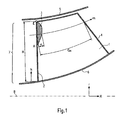
- Fig. 1 shows first a machine axis 8, around which a hub 6 shown schematically rotates. Between the hub 6 and a housing 5, an annular channel 7 is formed, through which the flow takes place.
- a rotor blade 1 with a front edge 2 and a trailing edge 4 is shown.
- the blade shown in Fig. 1 may also be formed in the form of a stator blade.
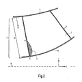
- FIG. 2 shows a further embodiment in which the blade 1 is also designed as a rotor blade or stator blade.
- the blade 1 is also designed as a rotor blade or stator blade.
- the same parts are provided with the same reference numerals as in Fig. 1.
- FIGS. 1 and 2 it can be seen that according to the invention the shortening of a chord length of the blade 1 takes place exclusively from the front edge 2.
- the largest return cuts 3 are provided in the regions at the blade ends.
- a cutback on a blade 1 can be provided both in the vicinity of the hub 6 and in the vicinity of the housing 5.
- Each pruning 3 according to the invention is such that the chord length of the blade 1 is shortened along the entirety or in parts of the blade height H between points A (starting point) and E (end point) provided on the front side.
- the blade height coordinate h which defines a relative blade height, serves to define the position of the points A and E.
- the blade height coordinate h has its origin at the end of the blade 1 closer to the starting point A.
- the starting point A is at a relative blade height of h / H in a range of: 0 ⁇ H / H point a ⁇ 0 .
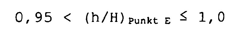
- the end point E is at a relative blade height of h / H in a range of: 0 . 95 ⁇ H / H Points ⁇ 1 . 0
- c is the relative cutback length in the meridian flow direction while C m denotes the meridional chord length. With m, the meridian streamline is specified. The illustration of these relationships has been omitted in FIG. 2 for reasons of clarity, but they also apply to the embodiment of FIG. 2.
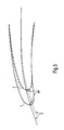
- the figure shows the envelope of the cutbacks 3 possible in the context of the present invention.
- the representation uses the relative cutback position s / S AE and the relative cutback length c / C m .
- the pruning always runs below an enveloping curve EKZ.
- the local cutback length c is at most 5% of the local meridional chord length C m .
- the cutback length c preferably increases only slowly from the starting point A and reaches its maximum in the range 0 . 6 ⁇ s / S AE ⁇ 0 . 95th
- FIG. 3 shows by way of example three curves of cut-backs 3.
- Fig. 5 is a Meridianstromlinienrough a blade 1 is shown in a simplified representation.
- the solid line shows the original profile of the bucket 1, while the dashed Line shows the shortened profile.
- the redesigning of the front edge 2 is carried out so as to obtain a shape which maintains the inclination of the tangent T to the chord at the leading edge exit point VP.
Landscapes
- Engineering & Computer Science (AREA)
- Mechanical Engineering (AREA)
- General Engineering & Computer Science (AREA)
- Structures Of Non-Positive Displacement Pumps (AREA)
- Organic Low-Molecular-Weight Compounds And Preparation Thereof (AREA)
Description
- Die Erfindung bezieht sich auf ein Reparaturverfahren für eine Schaufel einer Strömungsarbeitsmaschine gemäß den Merkmalen des Oberbegriffs des Hauptanspruchs.
- Ein solches Reparaturverfahren ist aus
US-A-5,281,062 bekannt. - Im Einzelnen bezieht sich die Erfindung auf ein Reparaturverfahren, bei welchem zumindest ein Teilbereich einer Vorderkante der Schaufel entfernt wird.
- Strömungsarbeitsmaschinen im Sinne der Erfindung sind beispielsweise Bläser, Verdichter, Pumpen und Ventilatoren, die in axialer, halbaxialer und radialer Bauart mit gasförmigem oder flüssigem Arbeitsmedium betrieben werden können.
- Die Strömungsarbeitsmaschine kann eine oder mehrere Stufen mit jeweils einem Rotor und einem Stator umfassen, in Einzelfällen kann die Stufe auch lediglich durch einen Rotor gebildet werden. Der Rotor umfasst eine Anzahl von Schaufeln, die mit der rotierenden Welle der Strömungsarbeitsmaschine verbunden sind und Energie an das Arbeitsmedium abgeben.
- Der Rotor kann mit oder ohne Deckband am äußeren Schaufelende ausgeführt sein.
- Der Stator kann aus einer Anzahl feststehender Schaufeln, die nabenseitig wie gehäuseseitig mit festem oder freiem Schaufelende ausgeführt sein können, bestehen.
- Die Rotortrommel und die Beschaufelung sind üblicherweise von einem Gehäuse umgeben, es kann jedoch auch auf ein Gehäuse verzichtet werden, beispielsweise bei Propellern oder Schiffsschrauben.
- Die Strömungsarbeitsmaschine kann auch einen Stator vor dem ersten Rotor, ein so genanntes Vorleitrad, aufweisen. Mindestens ein Stator oder ein Vorleitrad können abweichend von der unbeweglichen Fixierung auch drehbar gelagert sein, um den Anstellwinkel zu verändern. Eine derartige Verstellung kann beispielsweise durch eine von außerhalb des Ringkanals zugängliche Spindel erfolgen. Alternativ kann die Strömungsarbeitsmaschine bei Mehrstufigkeit auch zwei gegenläufige Wellen besitzen, so dass die Rotorschaufelreihen von Stufe zu Stufe die Drehrichtung wechseln. Hierbei existieren dann keine Statoren zwischen aufeinanderfolgenden Rotoren.
- Weiterhin kann die Strömungsarbeitsmaschine alternativ eine Nebenstufenkonfiguration aufweisen, bei welcher sich ein einstromiger Ringkanal hinter einer bestimmten Schaufelreihe in zwei konzentrische Ringkanäle aufteilt, die ihrerseits mindestens eine weitere Schaufelreihe umfassen.
- Die Effizienz und Betriebsstabilität von Strömungsarbeitsmaschinen wie Bläsern, Verdichtern, Pumpen oder Ventilatoren, sind über ihre Betriebszeit einer erheblichen Verschlechterung unterworfen, die eine Modifikation oder Nacharbeit von Teilen der Strömungsarbeitsmaschine erforderlich macht, welche schon länger im Einsatz sind.
- Ein weiterer Aspekt besteht darin, dass die ursprünglich erwartete Lebensdauer von Schaufeln und Scheiben nicht erreicht werden kann, da ein Bauteilverschleiß zu einer zunehmenden Schwingungsbelastung führt.
- So ist es in ungünstigen Fällen möglich, dass der im ursprünglichen Entwurf der Beschaufelung vorgesehene Abstand zur Stabilitätsgrenze der Strömungsarbeitsmaschine teilweise oder vollständig verloren geht oder Schaufeln und/oder Scheiben eine zu geringe tatsächliche Lebensdauer haben. Der Grund hierfür liegt beispielsweise in einer Vergrößerung der radialen Laufspalte, insbesondere an den Schaufelspitzen von Rotoren und der damit verbundenen Intensivierung der nachteiligen Durchströmung der Radialspalte von der Druck- zur Saugseite einer jeden Schaufel.
- Eine nachträgliche Verbesserung des Strömungsfeldes ist grundsätzlich entweder durch spezifische Maßnahmen am Gehäuse oder an der Beschaufelung möglich. Eine Möglichkeit besteht in einer besonderen Strukturierung des Gehäuses im Laufbereich der Schaufeln durch so genannte "casing treatments".
- Um Beschädigungen der Schaufeln zu reparieren, ist es aus dem Stand der Technik bekannt, die beschädigten Bereiche auszuschleifen, insbesondere, um Kerbwirkungen zu vermeiden. Derartige übliche Maßnahmen führen vielfach zu signifikanten Verschlechterungen der Leistung der Strömungsarbeitsmaschine. Weiterhin müssen die Schaufeln, die durch derartige Verfahren reparierbar sein sollen, erheblich überdimensioniert werden, um ausreichende Materialreserven zu bieten. Ein Reparaturverfahren ist beispielsweise aus der
DE 197 12 868 C1 bekannt. - Der Erfindung liegt die Aufgabe zugrunde, ein Reparaturverfahren der eingangs genannten Art zu schaffen, welches bei einfachem Aufbau und einfacher, kostengünstiger Durchführbarkeit bei hoher Sicherheit ein hohes Maß an Effizienz der Strömungsarbeitsmaschine bietet.
- Erfindungsgemäß wird die Aufgabe durch die Merkmalskombination des Hauptanspruchs gelöst, der Unteranspruch zeigt weitere vorteilhafte Ausgestaltungen der Erfindung.
- Erfindungsgemäß ist somit vorgesehen, dass ein Vorderkantenrückschnitt an mindestens einer der bestehenden Schaufeln der Strömungsarbeitsmaschine erfolgt, durch welchen sich die Betriebsleistungen und/oder die Lebensdauer der Strömungsarbeitsmaschine verbessern.
- Das erfindungsgemäß vorgeschlagene Reparaturverfahren erlaubt durch die spezielle Ausgestaltung des Vorderkantenrückschnitts eine Vergleichmäßigung und Beruhigung der Strömung im Schaufelrandbereich. Auf diese Weise kann insbesondere bei Rotoren in kritischen Fällen eine von dieser Strömung ausgehende Schwingungsanregung und die damit verbundene Lebensdauereinbuße vermieden werden.
- Insbesondere die im Fußbereich von Fanschaufeln auftretenden vibratorischen Verschleißerscheinungen, die durch Strömungsinstabilitäten im Blattspitzenbereich der Schaufeln hervorgerufen werden, werden durch die Anwendung des erfindungsgemäßen Reparaturverfahrens reduziert. Dies führt zu einer Erhöhung der Schaufel- und Scheibenlebensdauer.
- Die vorliegende Erfindung erlaubt zudem eine Steigerung der Betriebsleistungen von Strömungsarbeitsmaschinen. Erfindungsgemäß ist eine Erhöhung des Stufenwirkungsgrades von rund 0,5% möglich. Bei Einsatz der Erfindung am Fan eines Flugtriebwerks mit beispielsweise 25.000 Pfund Schub ergibt sich eine Reduzierung des spezifischen Kraftstoffverbrauchs von bis zu 0,5%. Ein möglicher Zugewinn an Stabilität, d.h. eine Erhöhung der Abreißgrenze der Strömungsarbeitsmaschine, ist mit rund 5% anzugeben.
- Im Folgenden wird die Erfindung anhand von Ausführungsbeispielen in Verbindung mit den Zeichnungen beschrieben.
- Dabei zeigt:
- Fig. 1
- ein erstes Ausführungsbeispiel einer Schaufelprofilkürzung durch einen erfindungsgemäßen Rückschnitt,
- Fig. 2
- ein weiteres Ausführungsbeispiel einer erfindungsgemäßen Schaufelprofilkürzung,
- Fig. 3
- ein Diagramm zur Verdeutlichung der im Rahmen der Erfindung möglichen Schaufelprofilkürzungen,
- Fig. 4
- eine Erläuterung der gewählten Dimensionierungen, und
- Fig. 5
- eine schematische Darstellung der Formgebung der Vorderkante durch einen erfindungsgemäßen Rückschnitt in der Schnittansicht längs der Meridianstromlinie einer Schaufel.
- Die Fig. 1 zeigt zunächst eine Maschinenachse 8, um welche sich eine schematisch dargestellte Nabe 6 dreht. Zwischen der Nabe 6 und einem Gehäuse 5 ist ein Ringkanal 7 ausgebildet, durch welchen die Strömung erfolgt.
- Bei dem in Fig. 1 gezeigten Ausführungsbeispiel ist eine Rotor-Schaufel 1 mit einer Vorderkante 2 und einer Hinterkante 4 dargestellt.
- Der erfindungsgemäß vorzunehmende Rückschnitt ist mit dem Bezugszeichen 3 gekennzeichnet.
- Die in Fig. 1 gezeichnete Schaufel kann auch in Form einer Statorschaufel ausgebildet sein.
- Die Fig. 2 zeigt ein weiteres Ausführungsbeispiel, bei welchem die Schaufel 1 ebenfalls als Rotorschaufel oder Statorschaufel ausgebildet ist. Gleiche Teile sind mit gleichen Bezugszeichen wie in Fig. 1 versehen.
- Aus den Fig. 1 und 2 ist ersichtlich, dass erfindungsgemäß die Verkürzung einer Sehnenlänge der Schaufel 1 ausschließlich von der Vorderkante 2 aus erfolgt. Die beitragsmäßig größten Rückschnitte 3 sind dabei in den Regionen an den Schaufelenden vorgesehen. Erfindungsgemäß kann sowohl in der Nähe der Nabe 6 als auch in der Nähe des Gehäuses 5 je ein Rückschnitt an einer Schaufel 1 vorgesehen sein.
- Jeder Rückschnitt 3 ist erfindungsgemäß so beschaffen, dass die Sehnenlänge der Schaufel 1 entlang der Gesamtheit oder in Teilen der Schaufelhöhe H zwischen an der Vorderseite vorgesehenen Punkten A (Anfangspunkt) und E (Endpunkt) verkürzt ist.
- Erfindungsgemäß dient zur Definition der Lage der Punkte A und E die Schaufelhöhenkoordinate h, welche eine relative Schaufelhöhe definiert. Die Schaufelhöhenkoordinate h hat ihren Ursprung an dem näher am Anfangspunkt A gelegenen Ende der Schaufel 1. Der Anfangspunkt A befindet sich bei einer relativen Schaufelhöhe von h/H in einem Bereich von:

- Der Endpunkt E befindet sich bei einer relativen Schaufelhöhe von h/H in einem Bereich von:
- In Fig. 1 ist mit c die relative Rückschnittlänge in Meridianströmungsrichtung dargestellt, während Cm die meridionale Sehnenlänge bezeichnet. Mit m ist der Meridian-Stromlinienverlauf angegeben. Auf die Darstellung dieser Zusammenhänge wurde in Fig. 2 aus Gründen der Übersichtlichkeit verzichtet, sie gelten jedoch auch bei dem Ausführungsbeispiel der Fig. 2.
- Die Fig. 4 zeigt die Definition der relativen Rückschnittposition s in radialer Richtung sowie der gesamten radialen Rückschnittlänge SAE.
- Aus Fig. 3 ist der Verlauf möglicher Vorderkantenrückschnitte 3 erläutert. Die Figur zeigt die Einhüllende der im Rahmen der vorliegenden Erfindung möglichen Rückschnitte 3. Die Darstellung bedient sich der relativen Rückschnittsposition s/SAE und der relativen Rückschnittlänge c/Cm. Erfindungsgemäß verläuft der Rückschnitt stets unterhalb eines einhüllenden Kurvenzuges EKZ. Am Anfangspunkt A beträgt die lokale Rückschnittlänge c maximal 5% der dortigen meridionalen Sehnenlänge Cm. Die Rückschnittlänge c nimmt bevorzugterweise vom Anfangspunkt A aus nur langsam zu und erreicht ihr Maximum im Bereich

- In diesem Bereich kann die relative Rückschnittlänge bis zu c/Cm = 0,25 betragen. Bis zum Endpunkt E geht die relative Rückschnittlänge auf mindestens c/Cm = 0,05 zurück.
- Die oben stehende Definition ermöglicht unterschiedlichste Realisierungen der Rückschnittgeometrien, die Fig. 3 zeigt beispielhaft drei Kurven von Rückschnitten 3.
- In Fig. 5 ist ein Meridianstromlinienschnitt einer Schaufel 1 in vereinfachter Darstellung gezeigt. Die durchgezogene Linie zeigt das Originalprofil der Schaufel 1, während die gestrichelte Linie das gekürzte Profil wiedergibt. Erfindungsgemäß ist es besonders günstig, wenn bei dem vorgesehenen Vorderkanten-Rückschnitt die Neugestaltung der Vorderkante 2 so ausgeführt wird, dass sie eine Form erhält, welche die Neigung der Tangente T an die Profilsehne am Vorderkantenaustrittspunkt VP aufrecht erhält.
-
- 1
- Schaufel
- 2
- Vorderkante
- 3
- Rückschnitt
- 4
- Hinterkante
- 5
- Gehäuse
- 6
- Nabe
- 7
- Ringkanal
- 8
- Maschinenachse
- h
- relative Schaufelhöhe
- H
- Schaufelhöhe
- s
- relative Rückschnittposition in radialer Richtung
- c
- relative Rückschnittlänge in Meridianströmungsrichtung
- Cm
- meridionale Sehnenlänge
- SAE
- radiale Rückschnittlänge
- m
- Meridian-Stromlinienverlauf
- T
- Profilsehnentangente an der Vorderkante
- A
- Anfangspunkt
- E
- Endpunkt
- VP
- Vorderkantenaustrittspunkt
- EKZ
- einhüllender Kurvenzug
Claims (2)
- Reparaturverfahren für eine Schaufel (1) einer Strömungsarbeitsmaschine, bei welchem zumindest ein Teilbereich einer Vorderkante (2) der Schaufel (1) entfernt wird,
dadurch gekennzeichnet,
dass ein Rückschnitt (3) der Schaufel (1) zwischen zwei Punkten (A) und (E) erfolgt, deren Lage auf dem ursprünglichen Profil der Vorderkante (2) der Schaufel (1) folgender Beziehung folgt:- Punkt (A) ist der Anfangspunkt und liegt in einem Bereich der relativen Schaufelhöhe von (h/H) von - Punkt (E) ist der Endpunkt und liegt in einem Bereich der relativen Schaufelhöhe (h/H) von
 - wobei (h) die Schaufelhöhenkoordinate (h) ist, welche ihren Ursprung an dem näher am Anfangspunkt (A) gelegenen Ende der Schaufel hat und wobei (H) die Schaufelhöhe ist,- dass der Verlauf des Rückschnitts durch das Verhältnis der relativen Rückschnittposition (s/SAE) und der relativen Rückschnittlänge (c/Cm) definiert ist, wobei- (c) die lokale Rückschnittlänge in Meridianströmungsrichtung ist,- (Cm) die meridionale Sehnenlänge ist,- (s) die lokale Rückschnittlänge in radialer Richtung ist, und- (SAE) die radiale Rückschnittlänge ist,- wobei die lokale Rückschnittlänge (c) vom Punkt (A) aus langsam zunimmt und ihr Maximum im Bereich 0,60 < s/SAE < 0,95 erreicht, wobei dort die relative Rückschnittlänge bis zu c/Cm = 0,25 beträgt, wobei die relative Rückschnittlänge (c/Cm) auf mindestens c/Cm = 0,05 zurückgeht.
 - Verfahren nach Anspruch 1, dadurch gekennzeichnet, dass die Vorderkante in einer Form ausgebildet wird, bei welcher die Neigung einer Tangente (T) an die Profilsehne in einem Vorderkantenaustrittspunkt (VP) bei dem rückgeschnittenen Profil der Schaufel gleich ist zu der am Originalprofil.
Applications Claiming Priority (2)
| Application Number | Priority Date | Filing Date | Title |
|---|---|---|---|
| DE10340827 | 2003-09-04 | ||
| DE10340827A DE10340827A1 (de) | 2003-09-04 | 2003-09-04 | Reparaturverfahren für eine Schaufel einer Strömungsarbeitsmaschine |
Publications (3)
| Publication Number | Publication Date |
|---|---|
| EP1512490A2 EP1512490A2 (de) | 2005-03-09 |
| EP1512490A3 EP1512490A3 (de) | 2005-10-19 |
| EP1512490B1 true EP1512490B1 (de) | 2007-09-05 |
Family
ID=34129648
Family Applications (1)
| Application Number | Title | Priority Date | Filing Date |
|---|---|---|---|
| EP04018923A Expired - Lifetime EP1512490B1 (de) | 2003-09-04 | 2004-08-10 | Reparaturverfahren für eine Schaufel einer Strömungsarbeitsmaschine |
Country Status (3)
| Country | Link |
|---|---|
| US (1) | US7293964B2 (de) |
| EP (1) | EP1512490B1 (de) |
| DE (2) | DE10340827A1 (de) |
Families Citing this family (9)
| Publication number | Priority date | Publication date | Assignee | Title |
|---|---|---|---|---|
| US20070269316A1 (en) * | 2006-05-18 | 2007-11-22 | Williams Andrew D | Turbine blade with trailing edge cutback and method of making same |
| US20090178278A1 (en) * | 2008-01-16 | 2009-07-16 | Quinn Daniel E | Method of reverse engineering |
| FR2983757B1 (fr) * | 2011-12-07 | 2014-09-12 | Snecma | Procede de reformage d'une aube de turbomachine comportant au moins une zone deformee par grenaillage |
| US10428657B2 (en) * | 2013-06-21 | 2019-10-01 | Pratt & Whitney Canada Corp. | Method for repairing a blade |
| US10125611B2 (en) | 2016-02-17 | 2018-11-13 | General Electric Company | System and method for in situ repair of turbine blades of gas turbine engines |
| JP7752467B2 (ja) * | 2019-08-29 | 2025-10-10 | 三菱重工コンプレッサ株式会社 | インペラ、及び遠心圧縮機 |
| US12018583B2 (en) * | 2019-11-22 | 2024-06-25 | Pratt & Whitney Canada Corp. | Impeller with hub sweep |
| CN112620872B (zh) * | 2020-12-09 | 2022-01-28 | 河北工业大学 | 基于视触融合的航空发动机叶片修复系统的坐标转换方法 |
| CN114367783A (zh) * | 2022-01-10 | 2022-04-19 | 广东韶钢松山股份有限公司 | 一种风机振动的检修方法 |
Family Cites Families (4)
| Publication number | Priority date | Publication date | Assignee | Title |
|---|---|---|---|---|
| NL157261B (nl) * | 1969-10-15 | 1978-07-17 | Kawasaki Heavy Ind Ltd | Werkwijze voor het aanpassen aan het gewenste motortoerental van een scheepsschroef. |
| US5197191A (en) * | 1991-03-04 | 1993-03-30 | General Electric Company | Repair of airfoil edges |
| DE19712868C1 (de) * | 1997-03-27 | 1998-10-01 | Mtu Muenchen Gmbh | Reparaturverfahren für im Blattsitzenbereich beschädigte Schaufelblätter von Strömungsmaschinen, sowie Reparaturkörper zur Durchführung des Verfahrens |
| DE19831736C2 (de) * | 1998-07-15 | 2000-05-31 | Mtu Muenchen Gmbh | Verfahren zur Reparatur und Herstellung eines integral beschaufelten Rotors für eine Strömungsmaschine |
-
2003
- 2003-09-04 DE DE10340827A patent/DE10340827A1/de not_active Withdrawn
-
2004
- 2004-08-10 EP EP04018923A patent/EP1512490B1/de not_active Expired - Lifetime
- 2004-08-10 DE DE502004004857T patent/DE502004004857D1/de not_active Expired - Lifetime
- 2004-09-03 US US10/933,256 patent/US7293964B2/en not_active Expired - Fee Related
Also Published As
| Publication number | Publication date |
|---|---|
| EP1512490A3 (de) | 2005-10-19 |
| EP1512490A2 (de) | 2005-03-09 |
| DE10340827A1 (de) | 2005-03-31 |
| US20050084368A1 (en) | 2005-04-21 |
| DE502004004857D1 (de) | 2007-10-18 |
| US7293964B2 (en) | 2007-11-13 |
Similar Documents
| Publication | Publication Date | Title |
|---|---|---|
| EP1382855B1 (de) | Strömungsarbeitsmaschine mit integriertem Fluidzirkulationssystem | |
| DE602004006323T2 (de) | Verfahren zur Herstellung einer Turbine mit Turbinenschaufeln unterschiedlicher Resonanzfrequenzen samt einer solchen Turbine | |
| EP2003292B1 (de) | Strömungsarbeitsmaschine aufweisend ein Schaufeldeckband mit Überstand | |
| EP2025945B1 (de) | Strömungsarbeitsmaschine mit Ringkanalwandausnehmung | |
| EP2249043B1 (de) | Strömungsarbeitsmaschine mit Fluidentnahme | |
| EP2182172B1 (de) | Strömungsarbeitsmaschine mit Fluidzufuhr | |
| EP2275643B1 (de) | Triebwerkschaufel mit überhöhter Vorderkantenbelastung | |
| EP2096260A2 (de) | Strömungsarbeitsmaschine mit Rotorenanordnungen mit niedrigen Rotoraustrittswinkeln | |
| EP3408503B1 (de) | Strömungsmaschine mit beschaufeltem diffusor | |
| DE102007056953A1 (de) | Strömungsarbeitsmaschine mit Ringkanalwandausnehmung | |
| EP2921716B1 (de) | Schaufelreihengruppe | |
| EP3536974B1 (de) | Gasturbinenverdichter | |
| EP1637697B1 (de) | Strömungs-Arbeits-Maschine mit Axialspaltkonzentrationen kleiner als 1 | |
| EP2294286A2 (de) | Deckband für laufschaufeln einer stromungsmaschine | |
| DE102007024840A1 (de) | Strömungsarbeitsmaschinenschaufel mit Multi-Profil-Gestaltung | |
| EP1512490B1 (de) | Reparaturverfahren für eine Schaufel einer Strömungsarbeitsmaschine | |
| EP1970542B1 (de) | Drosselgradabhängige Schaufelverstellung bei Strömungsarbeitsmaschinen | |
| EP2275647A2 (de) | Strömungsarbeitsmaschine mit Schaufelreihengruppe | |
| WO2005116404A1 (de) | Schaufelblatt mit übergangszone | |
| EP1865148B1 (de) | Strömungsarbeitsmaschine mit Rotoren hoher spezifischer Energieabgabe | |
| EP2275690A2 (de) | Axialverdichter, insbesondere für eine Fluggasturbine | |
| EP4089264A1 (de) | Gasturbinen-schaufelanordnung | |
| EP3428391A1 (de) | Turbomaschinen-schaufelgitter | |
| EP3246521A1 (de) | Auflauffläche für leitschaufeldeck- und laufschaufelgrundplatte | |
| WO2015149904A1 (de) | Turbinenrad eines abgasturboladers |
Legal Events
| Date | Code | Title | Description |
|---|---|---|---|
| PUAI | Public reference made under article 153(3) epc to a published international application that has entered the european phase |
Free format text: ORIGINAL CODE: 0009012 |
|
| AK | Designated contracting states |
Kind code of ref document: A2 Designated state(s): AT BE BG CH CY CZ DE DK EE ES FI FR GB GR HU IE IT LI LU MC NL PL PT RO SE SI SK TR |
|
| AX | Request for extension of the european patent |
Extension state: AL HR LT LV MK |
|
| PUAL | Search report despatched |
Free format text: ORIGINAL CODE: 0009013 |
|
| AK | Designated contracting states |
Kind code of ref document: A3 Designated state(s): AT BE BG CH CY CZ DE DK EE ES FI FR GB GR HU IE IT LI LU MC NL PL PT RO SE SI SK TR |
|
| AX | Request for extension of the european patent |
Extension state: AL HR LT LV MK |
|
| 17P | Request for examination filed |
Effective date: 20051207 |
|
| GRAP | Despatch of communication of intention to grant a patent |
Free format text: ORIGINAL CODE: EPIDOSNIGR1 |
|
| GRAS | Grant fee paid |
Free format text: ORIGINAL CODE: EPIDOSNIGR3 |
|
| AKX | Designation fees paid |
Designated state(s): DE FR GB |
|
| GRAA | (expected) grant |
Free format text: ORIGINAL CODE: 0009210 |
|
| AK | Designated contracting states |
Kind code of ref document: B1 Designated state(s): DE FR GB |
|
| REG | Reference to a national code |
Ref country code: GB Ref legal event code: FG4D Free format text: NOT ENGLISH |
|
| REF | Corresponds to: |
Ref document number: 502004004857 Country of ref document: DE Date of ref document: 20071018 Kind code of ref document: P |
|
| GBT | Gb: translation of ep patent filed (gb section 77(6)(a)/1977) |
Effective date: 20071114 |
|
| ET | Fr: translation filed | ||
| PLBE | No opposition filed within time limit |
Free format text: ORIGINAL CODE: 0009261 |
|
| STAA | Information on the status of an ep patent application or granted ep patent |
Free format text: STATUS: NO OPPOSITION FILED WITHIN TIME LIMIT |
|
| 26N | No opposition filed |
Effective date: 20080606 |
|
| REG | Reference to a national code |
Ref country code: DE Ref legal event code: R082 Ref document number: 502004004857 Country of ref document: DE Representative=s name: HOEFER & PARTNER, DE |
|
| REG | Reference to a national code |
Ref country code: DE Ref legal event code: R082 Ref document number: 502004004857 Country of ref document: DE Representative=s name: HOEFER & PARTNER, DE Effective date: 20130402 Ref country code: DE Ref legal event code: R081 Ref document number: 502004004857 Country of ref document: DE Owner name: ROLLS-ROYCE DEUTSCHLAND LTD & CO KG, DE Free format text: FORMER OWNER: ROLLS-ROYCE DEUTSCHLAND LTD & CO KG, 15827 BLANKENFELDE, DE Effective date: 20130402 Ref country code: DE Ref legal event code: R082 Ref document number: 502004004857 Country of ref document: DE Representative=s name: HOEFER & PARTNER PATENTANWAELTE MBB, DE Effective date: 20130402 |
|
| REG | Reference to a national code |
Ref country code: FR Ref legal event code: PLFP Year of fee payment: 13 |
|
| REG | Reference to a national code |
Ref country code: FR Ref legal event code: PLFP Year of fee payment: 14 |
|
| PGFP | Annual fee paid to national office [announced via postgrant information from national office to epo] |
Ref country code: DE Payment date: 20170829 Year of fee payment: 14 Ref country code: GB Payment date: 20170829 Year of fee payment: 14 Ref country code: FR Payment date: 20170825 Year of fee payment: 14 |
|
| REG | Reference to a national code |
Ref country code: DE Ref legal event code: R082 Ref document number: 502004004857 Country of ref document: DE |
|
| REG | Reference to a national code |
Ref country code: DE Ref legal event code: R119 Ref document number: 502004004857 Country of ref document: DE |
|
| GBPC | Gb: european patent ceased through non-payment of renewal fee |
Effective date: 20180810 |
|
| PG25 | Lapsed in a contracting state [announced via postgrant information from national office to epo] |
Ref country code: DE Free format text: LAPSE BECAUSE OF NON-PAYMENT OF DUE FEES Effective date: 20190301 |
|
| PG25 | Lapsed in a contracting state [announced via postgrant information from national office to epo] |
Ref country code: FR Free format text: LAPSE BECAUSE OF NON-PAYMENT OF DUE FEES Effective date: 20180831 |
|
| PG25 | Lapsed in a contracting state [announced via postgrant information from national office to epo] |
Ref country code: GB Free format text: LAPSE BECAUSE OF NON-PAYMENT OF DUE FEES Effective date: 20180810 |