EP1511971B1 - Inclinometre optique - Google Patents
Inclinometre optique Download PDFInfo
- Publication number
- EP1511971B1 EP1511971B1 EP03735412A EP03735412A EP1511971B1 EP 1511971 B1 EP1511971 B1 EP 1511971B1 EP 03735412 A EP03735412 A EP 03735412A EP 03735412 A EP03735412 A EP 03735412A EP 1511971 B1 EP1511971 B1 EP 1511971B1
- Authority
- EP
- European Patent Office
- Prior art keywords
- medium
- camera
- boundary layer
- inclination
- radiation
- Prior art date
- Legal status (The legal status is an assumption and is not a legal conclusion. Google has not performed a legal analysis and makes no representation as to the accuracy of the status listed.)
- Expired - Lifetime
Links
- 230000003287 optical effect Effects 0.000 title claims abstract description 23
- 230000005855 radiation Effects 0.000 claims abstract description 62
- 239000007788 liquid Substances 0.000 claims abstract description 36
- 238000011156 evaluation Methods 0.000 claims abstract description 19
- 238000000034 method Methods 0.000 claims description 13
- 230000005540 biological transmission Effects 0.000 claims description 9
- 239000007787 solid Substances 0.000 claims description 7
- 230000001419 dependent effect Effects 0.000 claims description 3
- 239000004065 semiconductor Substances 0.000 claims description 2
- 238000006243 chemical reaction Methods 0.000 claims 1
- 239000000126 substance Substances 0.000 claims 1
- 230000002277 temperature effect Effects 0.000 claims 1
- 230000007704 transition Effects 0.000 description 12
- 230000008859 change Effects 0.000 description 8
- 239000007789 gas Substances 0.000 description 6
- 238000005259 measurement Methods 0.000 description 6
- QSHDDOUJBYECFT-UHFFFAOYSA-N mercury Chemical compound [Hg] QSHDDOUJBYECFT-UHFFFAOYSA-N 0.000 description 5
- 229910052753 mercury Inorganic materials 0.000 description 5
- 238000013461 design Methods 0.000 description 4
- 238000004458 analytical method Methods 0.000 description 3
- 238000001514 detection method Methods 0.000 description 3
- 238000009736 wetting Methods 0.000 description 3
- 230000008901 benefit Effects 0.000 description 2
- 238000010276 construction Methods 0.000 description 2
- 230000000694 effects Effects 0.000 description 2
- 230000007613 environmental effect Effects 0.000 description 2
- 239000012530 fluid Substances 0.000 description 2
- 238000003384 imaging method Methods 0.000 description 2
- 230000010354 integration Effects 0.000 description 2
- 239000002245 particle Substances 0.000 description 2
- 238000002834 transmittance Methods 0.000 description 2
- 229920001817 Agar Polymers 0.000 description 1
- 241000238633 Odonata Species 0.000 description 1
- 238000010521 absorption reaction Methods 0.000 description 1
- 230000006978 adaptation Effects 0.000 description 1
- 230000032683 aging Effects 0.000 description 1
- 230000003679 aging effect Effects 0.000 description 1
- 230000004075 alteration Effects 0.000 description 1
- 238000004040 coloring Methods 0.000 description 1
- 239000002872 contrast media Substances 0.000 description 1
- 238000012937 correction Methods 0.000 description 1
- 230000002596 correlated effect Effects 0.000 description 1
- 230000000875 corresponding effect Effects 0.000 description 1
- 230000003247 decreasing effect Effects 0.000 description 1
- 230000008030 elimination Effects 0.000 description 1
- 238000003379 elimination reaction Methods 0.000 description 1
- 238000002594 fluoroscopy Methods 0.000 description 1
- 230000005484 gravity Effects 0.000 description 1
- 238000005286 illumination Methods 0.000 description 1
- 238000013507 mapping Methods 0.000 description 1
- 239000000843 powder Substances 0.000 description 1
- 230000008569 process Effects 0.000 description 1
- 238000012545 processing Methods 0.000 description 1
- 229920002545 silicone oil Polymers 0.000 description 1
- 230000003595 spectral effect Effects 0.000 description 1
- XLYOFNOQVPJJNP-UHFFFAOYSA-N water Substances O XLYOFNOQVPJJNP-UHFFFAOYSA-N 0.000 description 1
Images


Classifications
-
- G—PHYSICS
- G01—MEASURING; TESTING
- G01C—MEASURING DISTANCES, LEVELS OR BEARINGS; SURVEYING; NAVIGATION; GYROSCOPIC INSTRUMENTS; PHOTOGRAMMETRY OR VIDEOGRAMMETRY
- G01C9/00—Measuring inclination, e.g. by clinometers, by levels
- G01C9/18—Measuring inclination, e.g. by clinometers, by levels by using liquids
- G01C9/20—Measuring inclination, e.g. by clinometers, by levels by using liquids the indication being based on the inclination of the surface of a liquid relative to its container
-
- G—PHYSICS
- G01—MEASURING; TESTING
- G01C—MEASURING DISTANCES, LEVELS OR BEARINGS; SURVEYING; NAVIGATION; GYROSCOPIC INSTRUMENTS; PHOTOGRAMMETRY OR VIDEOGRAMMETRY
- G01C9/00—Measuring inclination, e.g. by clinometers, by levels
- G01C9/02—Details
- G01C9/06—Electric or photoelectric indication or reading means
- G01C2009/066—Electric or photoelectric indication or reading means optical
Definitions
- the invention relates to an optical inclinometer according to the preamble of claim 1, a method for measuring the inclination of a device according to the preamble of claim 17 and a geodetic device with such a inclinometer.
- Inclinometers of various designs have long been used in all areas in which the position of a device must be considered. This applies in particular to measurements in the geodesic area or in construction.
- a biaxial inclinometer in which a geometric figure is projected onto a linear array via a tilt-sensitive and beam-deflecting sensor.
- the sensor includes a liquid whose position relative to the device leads to an influence or deflection of the projection of the figure on the linear array.
- a simple tilt sensor which has a sealed, liquid-filled vessel.
- An inside of the vessel has a bulged surface in which a drop of mercury rests.
- the vessel and the liquid contained therein are transilluminated by a light source and the light radiation is registered by a detector of four photodiodes as a simple quadrant sensor. From the location of the caused by the mercury drop shading can be concluded that the inclination of the sensor.
- DE 3639284 describes an optical inclinometer.
- the objects of the present invention are to provide an optical inclinometer which is simple Having structure at a comparison with simple shading blades improved measurement accuracy.
- Another object is to provide an inclinometer which has a minimum of mechanical and optical parts and thereby has increased robustness and impact resistance.
- Another object of the present invention is to ensure structural integrability in geodetic or structural engineering devices. This applies in particular to the use of existing electronic components as evaluation devices.
- the present invention relates to an optical inclinometer.
- a radiation source radiation is generated, with which a medium is imaged on a camera.
- the medium is received by a receiving element.
- This receiving element may for example consist of a can for a liquid or a holder for a pendulum.
- the figure does not have to correspond to a visually exact figure.
- Essential is the fluoroscopy of the receiving element with at least one therein or held by this first medium.
- the image of this medium or part of this medium on the camera can optionally be evaluated by image processing, so that, for example, aberrations, such as distortions, can be considered and corrected.
- imaging should thus be understood as a radiation of the recording element in which an image which can be evaluated by the camera produces at least one of the first medium or a part of the first medium.
- the radiation used can be in the visible but also in the invisible spectral range and is usually determined by the technical and physical parameters of the radiation source, camera and medium.
- a radiation source light-emitting diodes or lasers, in particular semiconductor lasers, can be used in addition to conventional lamps of various types.
- the medium is transilluminated with this radiation or else the medium serves to shadow the radiation.
- the components of the image imaged on the camera, or at least parts of the medium can now include light-dark transitions, including the shadow cast of the medium on the camera, or else a boundary layer between two media.
- the medium is selected as a first medium in coordination with a second medium so that, for example, as an effect, the transition can be seen as a cut-off line or a particularly pronounced boundary layer is formed. Basically, both effects can be used equally.
- an adaptation of the transmittances or the transmission coefficients can also take place in the case of the media.
- liquids are mercury, water or silicone oil. Both the image of the boundary layer and the light-dark transition or a combination of the two can be used to determine the position of the first medium. In order to achieve an intensification of the boundary layer, this can be made more easily registrable by further measures. For example, floating particles can be distributed on the boundary layer, which cause an increased absorption of the radiation in this area. It is also possible to place a float-like solid on the boundary layer which, in turn, may be transmissive or impermeable to radiation.
- the image of the first medium or the transition between the two media is projected onto the camera and recorded there and converted into electronic signals.
- a suitable camera for example, a CCD camera or a CMOS camera can be used.
- Such a camera is available, for example, as a CMOS monochrome image sensor ADCS 2120 Agilent, which has a field of 640 x 480 pixel points.
- the signals generated by the camera are analyzed by an evaluation unit and evaluated with regard to the inclination of the device.
- a separate block or its own component can be used.
- the function of this evaluation unit in a built-in a rangefinder inclinometer can also be taken over by the electronics used for the distance measurement.
- sources already used for other purposes as a radiation source.
- a part of the laser light possibly used there for distance measurement could be decoupled and, possibly after scattering or beam widening, used to image the medium.
- the inclination of the device can be concluded that the inclination of the device. If, for example, a camera is attached to a side surface of a rectangular container which is filled with a liquid, the one direction of inclination (here by way of example) can be determined from the angle of the liquid surface as the liquid horizon to the camera Pitch) are determined. If there is an exclusive inclination in the other axis (here, for example, transverse inclination), the inclination can be determined from the height of the liquid level. Combined inclinations in both axes lead to a change of both the angle and the position in terms of a height of the liquid horizon.
- a camera according to the invention makes it possible to resolve and evaluate the properties and features of the image of the first medium and, in particular, the course and position of the boundary or boundary layer.
- a correction or elimination of changes due to aging or environmental influences can be undertaken.
- Changes in the volume of the media can be easily taken into account, since the measurement of the longitudinal inclination, the course of the boundary or boundary layer in the image is detected and the angle can be analyzed independently of the absolute position.
- Banks can be determined by the width of the image of the boundary layer, and this process can be combined with self-calibration as already described.
- This self-calibration can run permanently in the background during use of the inclinometer, so that a larger amount of data sets to inclination and width are available. From the values, if necessary using statistical or interpolation methods, the minimum value can be calculated and equated with the horizontal position.
- a prerequisite for determining the inclination based on the width of the image of the boundary layer is a suitable vessel shape of the receiving element, which causes no leveling caused changes of the image of the boundary layer.
- this requirement is easy to implement, for example by a vessel with parallel side walls. In particular, losses of the medium or its density changes can be compensated in this way.
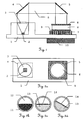
- a first embodiment of the inventive optical inclinometer with the integration of all components on a plate as a common base 1 is shown schematically in side view.
- a radiation source 2 visible or non-visible radiation S is emitted perpendicular to the base 1.
- the radiation S is collimated by a lens 3 and redirected via a first deflecting element 4 and a second deflecting element 5 so that it is incident perpendicularly to the base 1.
- a receiving element 6 with a base surface oriented to the base 1 is 7 and a second deflecting element oriented second surface 8 attached.
- a camera 9 Between base 1 and the receiving element or its first surface 7 is a camera 9, which is connected to an evaluation unit 10.
- the beam path and radiation reception components on the one side of the base 1, the evaluation unit 10 but mounted on the opposite side of the base 1, but in principle can also be a different arrangement of the components or the evaluation unit 10th to get voted.
- This arrangement thus offers the advantage of integration of all electronic components on a common base 1, which may be formed, for example, as a printed circuit board.
- the deflecting elements 4 and 5 can be designed as reflective components, for example as prisms or mirrors. In principle, however, a suitable deflection can also take place without special components, for example by a reflection on the inside of a housing, wherein this reflection can also have scattering or diffuse character.
- a deflection can also be dispensed with if it is ensured that at least partial areas of the receiving element 6 are illuminated by radiation S of the radiation source 2 or camera 9.
- a suitable orientation of radiation source 2 and receiving element 6 or camera 9 can also be effected by means of a curved or angled base 1. Basically, however, in the absence of mounting on a common base 1, but also a direct assembly of the components take place on each other, as in a second inventive embodiment in Figure 7 and Figure 8 is pictured.
- FIG. 2a shows this first embodiment of the inclinometer in plan view.
- the radiation emitted by the radiation source 2 is collimated by a lens 3 and guided to the receiving element 6 via a first deflecting element 4 and a second deflecting element 5.
- This receiving element is applied to a camera 9.
- the radiation source 2 and the camera 9 are mounted on a substantially planar base plate as a base 1.
- the receiving element 6 is at least a first medium. Possible embodiments are in Fig.2b to Fig.2d shown.
- the partial filling of the receiving element with a radiopaque first medium 11 is shown as a possible embodiment.
- the remaining area of the receiving element can be filled with a second medium 12, but this second medium can also be replaced by a vacuum.
- the second medium 12 is selected to have at least partial transmission of the radiation. This embodiment creates a light-dark contrast between the two media, which can be detected by the camera.
- FIG 2c a further embodiment of the filling of the receiving element with a radiation-permeable first medium 13 is shown.
- the remaining space of the receiving element can in turn be filled by a second medium, which is also transparent to radiation in this example.
- a boundary layer 14 is formed, which is imaged on the camera and can be resolved by this.
- This boundary layer 14 For example, it can be enhanced in its detectability by applying small particles, such as a powder, or even more massive components, such as a float.
- Figure 2d shows the change in the position of the media in the receiving element at a tilt of the inclinometer. Shown is the change with respect to the camera, which is fixed relative to the base. The schematically illustrated position corresponds to a rotation of the in 2a shown counterknife counterclockwise and is referred to as longitudinal tilt. While the in Fig.2b and Fig.2c represented positions of the media correspond to a horizontal position of the inclinometer, provides Figure 2d the detectable by the camera position in the described rotation of the inclinometer. Due to the inclination, the radiation-permeable first medium 13 has moved within the receiving element. The changed position can be detected and determined by the orientation of the boundary layer 14.
- 3a-c In a synopsis, the position and the recognition of the boundary layer in the horizontal, inadvertent position of the inclinometer are once again clarified.
- 3a Radiation is guided on the receiving element 6 via the second deflection element 5 and imaged onto the camera 9 after passage through the volume of this receiving element.
- the perceptible by the camera image of the media in the recording element is in 3b shown.
- the radiation-permeable first medium 13 with its boundary layer is still oriented horizontally to the camera.
- 3 c schematically shows the image perceived by the camera.
- the image of the boundary layer 16 is projected. This image can be converted by the shading of the individual pixels into signals from which the position or orientation of the boundary layer is derived.
- the detection of a boundary layer between two radiopaque media offers the possibility to evaluate 16 edges in the image of the boundary layer for position determination.
- an evaluation of a pure shading of pixels can also take into account other properties.
- the recognition of gray values or by a color camera a more accurate resolution of the position of the boundary layer can be achieved.
- additional features such as color changes due to refraction or scattering can also be taken into account.
- FIG. 4a-c The change in the position of the boundary layer with an exclusive longitudinal inclination of the inclinometer or the base 1 is in Fig. 4a-c shown schematically.
- 4a shows the rotation of the inclinometer with respect to the vertical as longitudinal inclination.
- the boundary layer 14 remains unchanged in its absolute position and thus leveled with respect to the vector of gravity.
- the relative position of the boundary layer 14 changes as a situation relative to the base 1 or with respect to the camera.
- the boundary layer 14 is inclined.
- the corresponding image of the boundary layer 16 on the detector surface 15 is shown schematically in FIG Fig. 4c shown, this image now has an inclination relative to the camera or the detector surface.
- 5a-e The conditions are shown in a horizontally oriented inventive inclinometer in a side view.
- 5a shows the inclinometer in plan view
- 5 b a lateral view takes place in 5a a view from the right corresponds.
- 5 b is shown schematically in this side view of the structure of the inclinometer.
- a camera 9 is mounted, the medium or directly a receiving element 6 with a first surface 7 and a second surface 8 carries.
- the evaluation unit 10 is attached.
- Fig. 5c shows an abstracted representation of this side view of the 5 b after a 90 ° turn to the left. From the left, radiation S falls onto the receiving element 6 with the radiation-permeable first medium 13 located therein.
- FIG.5E shows the associated image of the boundary layer 16 on the detector surface 15th
- FIG. 6a-e the illustration is for an inclined inclinometer, wherein the rotation takes place about an axis oriented perpendicular to the previous rotation.
- a position resulting from such a rotation is called a bank.
- 6a shows the inclinometer in plan view
- Figure 6b shows the inclinometer in side view.
- 6C It can be seen that the boundary layer 14, which is formed as an example as a liquid level in the receiving element 6, is now inclined with respect to the axis of incidence of the radiation S.
- Fig.6d shown, the boundary layer 14 widened from the direction of the camera.
- 6E As shown, the image of the boundary layer 16 'on the detector surface now also widened, so that a larger number of pixels is affected.
- the width of the image of the boundary layer 16 'and the inclination of the inclinometer are correlated with each other, so that the inclination can be deduced from this width.
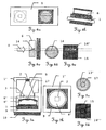
- the 7a-d show a second embodiment of an inventive inclinometer, which can be used for example in Lotstöcken or similar geodetic devices.
- the structure of such a inclinometer is shown schematically, with the inclinometer is in a horizontal position.
- the base 1 ' is substantially U-shaped and receives a radiation source 2 between the two legs.
- the radiation source emits radiation S, which is collimated by a lens 3.
- the collimated radiation S is then guided onto the receiving element 6 ', which is mounted directly or indirectly on a camera 9.
- the receiving element 6 has two surfaces, of which the first surface 7 is formed substantially flat, whereas the second surface 8 'has a curvature.
- the receiving element is filled with a liquid medium in which an air bubble is the second medium, with other gases or possibly another liquid can perform the function of the bubble.
- a drop of mercury in one Oil used so that this drop, in contrast to the bubble does not float on the surface but remains at the bottom of the vessel.
- the particular concrete design will depend, among other things, on building conditions. For example, the use of a drop of mercury would require the orientation of the second surface 8 'with the bulge toward the ground.
- Figure 7b shows a plan view of the inclinometer, in which the radiation source 2 is only hinted at omitting its holder. The radiation of this radiation source transilluminates the receiving element 6 'and falls on the underlying camera 9, which is mounted on the base 1'.
- In 7c is the view into the receiving element from the direction of the camera.
- a radiation-permeable first medium 13 ' is an air bubble 17 can be seen by their boundary layer.
- further features of the air bubble 17, such as a change in the degree of transmission due to the path covered in the radiation-transmissive first medium 13 'or a change in the transmittance due to a different transmission coefficient of the air bubble, can be used.
- the image of the boundary layer 16 "of the bubble on the detector surface 15 of the camera is in Fig.7d shown schematically.
- Figure 8a-e the ratios for a bank of the inclinometer are shown schematically.
- Figure 8a shows a tilt of the base 1 'to the right, which thus corresponds to a bank.
- the air bubble 17 has now moved within the receiving element 6 'to the left. This shift will also be in Fig.8b and Fig.8c shown.
- 8B corresponds to a view from the camera to the recording element.
- the bubble is now shifted to the left with respect to the camera.
- the associated image of the boundary layer 16 "on the detector surface 15 is in 8c shown.
- a suitable shape could be an aspheric curve with a curvature that increases more or less than a sphere.
- Fig.8d and Fig.8e is an example of an aspheric shape with decreasing outward radius of curvature shown. As the slope increases, the bubble will take on an increasingly oblong shape.
- Figure 8D is a view from the camera on the recording element shown. The bubble is now shifted to the left with respect to the camera and elongated. The associated image of the boundary layer 16 "'on the detector surface 15 is in Fig.8e shown.
- the pixels of the detector surface and in particular their number are shown purely schematically. In the real embodiments, the number of pixels available cameras is usually higher, so that higher resolutions of the position or angle can be achieved.
Landscapes
- Physics & Mathematics (AREA)
- Engineering & Computer Science (AREA)
- General Physics & Mathematics (AREA)
- Radar, Positioning & Navigation (AREA)
- Remote Sensing (AREA)
- Length Measuring Devices By Optical Means (AREA)
- Glass Compositions (AREA)
- Investigating Or Analysing Materials By Optical Means (AREA)
- Optical Fibers, Optical Fiber Cores, And Optical Fiber Bundles (AREA)
- Surgical Instruments (AREA)
- Lasers (AREA)
- Optical Recording Or Reproduction (AREA)
Claims (24)
- Inclinomètre optique, comprenant :• une source de rayonnement (2), pour produire un rayonnement (S) ;• au moins un premier milieu (11, 13), dont la position dépend de l'inclinaison ;• un élément de confinement (6, 6') pour le premier milieu (11, 13) ;• une caméra (9), de préférence une microcaméra CMOS ou à éléments CCD, pour enregistrer et convertir une représentation (16, 16', 16", 16"') en des signaux ; et• une unité d'évaluation (10), pour déterminer l'inclinaison ;caractérisé en ce que
la source de rayonnement (2) et la caméra (9) étant disposées de manière que, du fait du rayonnement, une image de l'allure d'une couche limite (14) au moins d'une partie du premier milieu (11, 13) soit imagée, indirectement ou directement, sur la caméra (9),
la caméra (9) et l'unité d'évaluation (10) sont réalisées de manière que l'image soit enregistrée par la caméra (9) et que l'allure de la couche limite (14) soit décomposée suivant une certaine résolution, et que l'allure de la couche limite (14) soit évaluée par l'unité d'évaluation (10) de manière à déterminer l'inclinaison. - Inclinomètre optique selon la revendication 1,
caractérisé en ce qu'
une image de l'allure d'au moins d'une partie d'une couche limite (14) sensiblement plane du premier milieu (11, 13) est imagée, indirectement ou directement, sur la caméra (9). - Inclinomètre optique selon la revendication 2,
caractérisé en ce que
le premier milieu (11, 13) est un liquide et la couche limite (14) est un horizon de liquide. - Inclinomètre optique selon la revendication 3,
caractérisé en ce que
l'élément de confinement (6, 6') est configuré sous forme de boîte cylindrique, de préférence remplie à moitié. - Inclinomètre optique selon l'une des revendications 2 à 4,
caractérisé en ce que
l'inclinomètre présente, en tant que deuxième milieu (12),• un gaz,• un liquide, ou• un corps solide, en particulier se présentant sous la forme d'un flotteur, dont la surface de contact avec le premier milieu (11, 13) définit la couche limite (14). - Inclinomètre optique selon la revendication 5,
caractérisé en ce que
le premier milieu (11, 13) et le deuxième milieu (12) présentent, pour le rayonnement (S), des degrés de transmission différents, de préférence des coefficients de transmission différents, en particulier en ce que l'un des deux milieux est opaque au rayonnement (S). - Inclinomètre optique selon la revendication 1,
caractérisé en ce que
le premier milieu (11, 13) est un corps solide du genre d'un pendule. - Inclinomètre optique selon l'une des revendications précédentes,
caractérisé en ce que
la source de rayonnement (2) présente un laser à semiconducteur ou une LED. - Inclinomètre optique selon l'une des revendications précédentes,
caractérisé en ce que
la source de rayonnement (2) et la caméra (9) sont disposées de manière que, dans la zone du premier milieu (11, 13), le rayonnement (S) soit guidé de manière sensiblement parallèle à une surface du premier milieu (11, 13). - Inclinomètre optique selon l'une des revendications précédentes,
caractérisé en ce que
l'élément de confinement (6, 6') est monté, indirectement ou directement, sur la caméra (9). - Inclinomètre optique selon l'une des revendications précédentes,
caractérisé en ce que
élément de confinement (6, 6') présente :• une première surface (7) transparente, plane, et• une deuxième surface (8) transparente,
orientées sensiblement parallèlement l'une à l'autre, la deuxième surface (8) étant plane ou incurvée. - Inclinomètre optique selon la revendication 11,
caractérisé en ce que
la caméra (9) présente une surface de détecteur (15) bidimensionnelle, orientée parallèlement à la première surface (7) et/ou à la deuxième surface (8) de l'élément de confinement (6, 6'). - Inclinomètre optique selon l'une des revendications précédentes,
caractérisé en ce que
la source de rayonnement (2) et la caméra (9) sont montées sur une base (1, 1') commune, de préférence une plaquette à circuit imprimé. - Inclinomètre optique selon la revendication 13,
caractérisé en ce que
la source de rayonnement (2) et la caméra (9) sont disposées de manière que le rayonnement (S) produit soit émis perpendiculairement à la surface de la base (1, 1'), et la direction de réception de la caméra (9) est orientée perpendiculairement à la surface de la base (1, 1'). - Inclinomètre optique selon la revendication 13 ou 14,
caractérisé en ce qu'
un trajet de rayon, allant de la source de rayonnement (2) à la caméra (9), présente au moins un élément de déviation (4, 5). - Appareil géodésique, en particulier télémètre ou barre de fil à plomb, avec un inclinomètre selon l'une des revendications 1 à 15.
- Procédé de masure de l'inclinaison d'un appareil, en particulier d'un appareil géodésique, avec :• une source de rayonnement (2), pour produire un rayonnement (S)• au moins un premier milieu (11, 13), dont la position dépend de l'inclinaison ;• un élément de confinement (6, 6') pour le premier milieu (11, 13) ;• une caméra (9), pour enregistrer des images ; et• une unité d'évaluation (10), pour déterminer l'inclinaison de l'appareil ;caractérisé en ce que
comprenant les étapes consistant à :- produire une image sur la caméra (9), au moyen du rayonnement (S) généré par la source de rayonnement, l'image contenant l'allure d'une couche limite au moins d'une partie du premier milieu (11, 13),- enregistrer et convertir l'image en des signaux, au moyen de la caméra (9),- déterminer l'inclinaison de l'appareil, à partir des signaux, au moyen de l'unité d'évaluation (10),
l'allure de la couche limite (14) est décomposée suivant une certaine résolution, et l'allure de la couche limite (14) est évaluée, de manière à déterminer l'inclinaison.
caractérisé en ce que - Procédé selon la revendication 17,
caractérisé en ce que
l'inclinaison de l'appareil est déterminée à partir de l'orientation et de la forme de la couche limite (14). - Procédé selon la revendication 17 ou 18,
caractérisé en ce que,
lors de la génération d'une image, le rayonnement (S) est guidé sensiblement parallèlement à une surface du premier milieu (11, 13). - Procédé selon l'une des revendications 17 à 19,
caractérisé en ce que
la détermination de l'inclinaison s'effectue en prenant en considération :• l'angle du premier milieu (11, 13) dans l'image, et• la position absolue du premier milieu (11, 13) dans l'image. - Procédé selon l'une des revendications 17 à 20,
caractérisé en ce qu'
un signal est émis lors de l'atteinte ou du dépassement d'une valeur d'inclinaison susceptible d'être prédéterminée. - Procédé selon l'une des revendications 17 à 21,
caractérisé en ce que,
lors de la détermination de l'inclinaison, des erreurs imputables à des effets de la température et/ou à des pertes de substance, au moins du premier milieu (11, 13), sont prises en considération, en particulier sont éliminées. - Procédé selon l'une des revendications 17 à 22,
caractérisé en ce que
lors de la génération d'une image, une couche limite (14), sensiblement plane, du premier milieu (11, 13) est imagée. - Procédé selon la revendication 23,
caractérisé en ce que
l'étendue, la forme et/ou la position de la couche limite (14) est/sont prise(s) en considération lors de la détermination de l'inclinaison de l'appareil.
Applications Claiming Priority (3)
| Application Number | Priority Date | Filing Date | Title |
|---|---|---|---|
| CH200209256 | 2002-06-07 | ||
| CH9562002 | 2002-06-07 | ||
| PCT/EP2003/005206 WO2003104748A1 (fr) | 2002-06-07 | 2003-05-17 | Inclinometre optique |
Publications (3)
| Publication Number | Publication Date |
|---|---|
| EP1511971A1 EP1511971A1 (fr) | 2005-03-09 |
| EP1511971B1 true EP1511971B1 (fr) | 2010-04-14 |
| EP1511971B8 EP1511971B8 (fr) | 2010-09-29 |
Family
ID=29721331
Family Applications (1)
| Application Number | Title | Priority Date | Filing Date |
|---|---|---|---|
| EP03735412A Expired - Lifetime EP1511971B8 (fr) | 2002-06-07 | 2003-05-17 | Inclinometre optique |
Country Status (8)
| Country | Link |
|---|---|
| US (1) | US7259842B2 (fr) |
| EP (1) | EP1511971B8 (fr) |
| JP (1) | JP4440096B2 (fr) |
| CN (1) | CN100547349C (fr) |
| AT (1) | ATE464537T1 (fr) |
| AU (1) | AU2003236674A1 (fr) |
| DE (1) | DE50312618D1 (fr) |
| WO (1) | WO2003104748A1 (fr) |
Families Citing this family (15)
| Publication number | Priority date | Publication date | Assignee | Title |
|---|---|---|---|---|
| EP1491855A1 (fr) * | 2003-06-23 | 2004-12-29 | Leica Geosystems AG | Détecteur d'inclinaison optique |
| GB0424890D0 (en) * | 2004-01-15 | 2004-12-15 | Koninkl Philips Electronics Nv | Method for detecting an orientation of a device and device having an orientation detector |
| WO2007128161A1 (fr) * | 2006-04-30 | 2007-11-15 | Appro Technology Inc. | Dispositif de contrôle de niveau horizontal |
| WO2010080340A1 (fr) * | 2009-01-06 | 2010-07-15 | Siemens Healthcare Diagnostics Inc. | Procédés et appareil de détermination d'un niveau de liquide dans un contenant à l'aide d'une imagerie |
| EP2423640A1 (fr) | 2010-08-23 | 2012-02-29 | Hexagon Technology Center GmbH | Capteur d'inclinaison pour un appareil et procédé de détermination de l'inclinaison d'un appareil |
| US8573147B1 (en) | 2011-09-13 | 2013-11-05 | Jeffrey M. Tanner | Pipe direction and size indicator |
| CN103206947B (zh) * | 2012-01-16 | 2016-09-28 | 中国科学院声学研究所 | 一种基于水准泡的倾角测量方法及其装置 |
| US9970750B2 (en) * | 2015-05-29 | 2018-05-15 | Nippon Steel & Sumitomo Metal Corporation | Shape inspection apparatus for metallic body and shape inspection method for metallic body |
| JP6632128B2 (ja) * | 2016-01-18 | 2020-01-15 | 株式会社トプコン | 液面反射式傾斜センサにおける容器の設計方法、該容器を有する傾斜センサ、及び該容器を有する傾斜センサの生産方法 |
| DE102019116833A1 (de) * | 2019-06-21 | 2020-12-24 | Albert Bauer | Libelle für eine Wasserwaage |
| CN110672041A (zh) * | 2019-10-15 | 2020-01-10 | 成都飞机工业(集团)有限责任公司 | 一种基于图像测量雾锥角的实验装置 |
| RU2740489C1 (ru) * | 2020-06-29 | 2021-01-14 | Объединенный Институт Ядерных Исследований (Оияи) | Лазерный инклинометр для длительной регистрации угловых наклонов земной поверхности |
| RU2747047C1 (ru) * | 2020-08-19 | 2021-04-23 | Объединенный Институт Ядерных Исследований (Оияи) | Лазерный инклинометр |
| CN112362031B (zh) * | 2020-11-13 | 2022-08-23 | 重庆大学 | 滑坡测量用倾角传感器及其使用方法 |
| CN117268326B (zh) * | 2023-09-13 | 2024-02-02 | 中国建筑第五工程局有限公司 | 一种大跨度公共建筑梁体拆模沉降检测设备 |
Family Cites Families (8)
| Publication number | Priority date | Publication date | Assignee | Title |
|---|---|---|---|---|
| DE3639284A1 (de) * | 1986-11-17 | 1988-05-26 | Precitronic | Sensor zur feststellung der tatsaechlichen und scheinbaren lotrichtung |
| JPH01109206A (ja) * | 1987-10-21 | 1989-04-26 | Asahi Optical Co Ltd | 自動水準器 |
| DE59510056D1 (de) * | 1995-11-14 | 2002-03-21 | Knestel Elektronik Gmbh | Verfahren und Vorrichtung zum Vermessen der Achsen und Radstellungen von Kraftfahrzeugen |
| US5794355A (en) * | 1996-06-03 | 1998-08-18 | Gateway 2000, Inc. | Rotationally actuated position sensor |
| US5940172A (en) * | 1998-06-03 | 1999-08-17 | Measurement Devices Limited | Surveying apparatus |
| JP3787736B2 (ja) * | 1997-10-08 | 2006-06-21 | 株式会社トプコン | 傾斜センサ |
| DE19854812A1 (de) * | 1997-12-03 | 1999-08-26 | Ricklefs | Winkelmeßvorrichtung zum Erfassen von Winkelabweichungen gegenüber einer Bezugslage |
| US6943339B2 (en) * | 2002-08-01 | 2005-09-13 | Vishay Infrared Components, Inc. | Tilt sensor and method of making same |
-
2003
- 2003-05-17 DE DE50312618T patent/DE50312618D1/de not_active Expired - Lifetime
- 2003-05-17 CN CNB038132338A patent/CN100547349C/zh not_active Expired - Fee Related
- 2003-05-17 WO PCT/EP2003/005206 patent/WO2003104748A1/fr active Application Filing
- 2003-05-17 AT AT03735412T patent/ATE464537T1/de not_active IP Right Cessation
- 2003-05-17 JP JP2004511773A patent/JP4440096B2/ja not_active Expired - Fee Related
- 2003-05-17 AU AU2003236674A patent/AU2003236674A1/en not_active Abandoned
- 2003-05-17 EP EP03735412A patent/EP1511971B8/fr not_active Expired - Lifetime
- 2003-05-17 US US10/516,730 patent/US7259842B2/en not_active Expired - Lifetime
Also Published As
| Publication number | Publication date |
|---|---|
| JP4440096B2 (ja) | 2010-03-24 |
| US7259842B2 (en) | 2007-08-21 |
| EP1511971B8 (fr) | 2010-09-29 |
| CN1659420A (zh) | 2005-08-24 |
| CN100547349C (zh) | 2009-10-07 |
| EP1511971A1 (fr) | 2005-03-09 |
| DE50312618D1 (de) | 2010-05-27 |
| AU2003236674A1 (en) | 2003-12-22 |
| JP2005529323A (ja) | 2005-09-29 |
| WO2003104748A1 (fr) | 2003-12-18 |
| ATE464537T1 (de) | 2010-04-15 |
| US20050225748A1 (en) | 2005-10-13 |
Similar Documents
| Publication | Publication Date | Title |
|---|---|---|
| EP1511971B1 (fr) | Inclinometre optique | |
| DE112007000198B4 (de) | Mehrachsiger Blasen-Hohlkörper | |
| EP2201326B1 (fr) | Procédé de détermination de distance | |
| CH692679A5 (de) | Photogrammetrische Kamera und photogrammetrisches Verfahren. | |
| WO2007059736A1 (fr) | Detecteur d'inclinaison | |
| DE102006055746A1 (de) | Verfahren zur Korrektur einer Volumenabbildungsgleichung zur Bestimmung eines Geschwindigkeitsfeldes von Teilchen in einem Volumen | |
| EP2609395A1 (fr) | Capteur d'inclinaison pour un appareil et procédé de détermination de l'inclinaison d'un appareil | |
| DE69726487T2 (de) | Neigungssensor und diesen verwendendes Vermessungsinstrument | |
| DE3924460A1 (de) | Winkelschrittgeber | |
| DE102016100656A1 (de) | Stereobilderfassungssystem | |
| DE19819610C1 (de) | Optischer Neigungsmesser | |
| WO2006069748A1 (fr) | Dispositif de mesure d'un objet et procede pour utiliser un dispositif de ce type | |
| EP0683888B1 (fr) | Appareil photographique de photogrammetrie, utile notamment pour effectuer des mesures photogrammetriques d'objets techniques | |
| DE102009019871B4 (de) | Hilfsvorrichtung zur Feinjustierung eines Laserstrahls auf einen vorgebbaren Zielpunkt | |
| DE19610941C2 (de) | Zweiachsiger Neigungsmesser und Verfahren zur Neigungsmessung | |
| DE4102579C2 (fr) | ||
| JP2000146574A (ja) | 傾斜および傾斜変化測定のための多軸式傾斜計 | |
| EP0626061B1 (fr) | Appareil de mesure | |
| WO2020065015A1 (fr) | Système de mesure lidar et procédé pour un système de mesure lidar | |
| DE19854812A1 (de) | Winkelmeßvorrichtung zum Erfassen von Winkelabweichungen gegenüber einer Bezugslage | |
| DE3308358C2 (fr) | ||
| DE4422886A1 (de) | Verfahren und Einrichtung zur optischen Bestimmung räumlicher Positionen einzelner reflektierender Objekte | |
| EP1418401A1 (fr) | Procédé et dispositif pour photogrammétrie aérienne ou spatiale | |
| DE3518966A1 (de) | Verfahren zur ermittlung der lage einer strichkreuzmarke | |
| DE102007044314A1 (de) | Digitale Zeilenkamera |
Legal Events
| Date | Code | Title | Description |
|---|---|---|---|
| PUAI | Public reference made under article 153(3) epc to a published international application that has entered the european phase |
Free format text: ORIGINAL CODE: 0009012 |
|
| 17P | Request for examination filed |
Effective date: 20041119 |
|
| AK | Designated contracting states |
Kind code of ref document: A1 Designated state(s): AT BE BG CH CY CZ DE DK EE ES FI FR GB GR HU IE IT LI LU MC NL PT RO SE SI SK TR |
|
| AX | Request for extension of the european patent |
Extension state: AL LT LV MK |
|
| DAX | Request for extension of the european patent (deleted) | ||
| GRAP | Despatch of communication of intention to grant a patent |
Free format text: ORIGINAL CODE: EPIDOSNIGR1 |
|
| GRAS | Grant fee paid |
Free format text: ORIGINAL CODE: EPIDOSNIGR3 |
|
| GRAA | (expected) grant |
Free format text: ORIGINAL CODE: 0009210 |
|
| AK | Designated contracting states |
Kind code of ref document: B1 Designated state(s): AT BE BG CH CY CZ DE DK EE ES FI FR GB GR HU IE IT LI LU MC NL PT RO SE SI SK TR |
|
| REG | Reference to a national code |
Ref country code: GB Ref legal event code: FG4D Free format text: NOT ENGLISH |
|
| REG | Reference to a national code |
Ref country code: CH Ref legal event code: EP |
|
| REG | Reference to a national code |
Ref country code: IE Ref legal event code: FG4D Free format text: LANGUAGE OF EP DOCUMENT: GERMAN |
|
| REG | Reference to a national code |
Ref country code: CH Ref legal event code: NV Representative=s name: KAMINSKI HARMANN PATENTANWAELTE EST. |
|
| REF | Corresponds to: |
Ref document number: 50312618 Country of ref document: DE Date of ref document: 20100527 Kind code of ref document: P |
|
| REG | Reference to a national code |
Ref country code: CH Ref legal event code: PK Free format text: DAS PRIORITAETSAKTENZEICHEN WURDE BERICHTIGT: CH 200200956 / 07.06.2002 |
|
| REG | Reference to a national code |
Ref country code: NL Ref legal event code: T3 |
|
| REG | Reference to a national code |
Ref country code: SE Ref legal event code: TRGR |
|
| PG25 | Lapsed in a contracting state [announced via postgrant information from national office to epo] |
Ref country code: ES Free format text: LAPSE BECAUSE OF FAILURE TO SUBMIT A TRANSLATION OF THE DESCRIPTION OR TO PAY THE FEE WITHIN THE PRESCRIBED TIME-LIMIT Effective date: 20100725 |
|
| REG | Reference to a national code |
Ref country code: IE Ref legal event code: FD4D |
|
| BERE | Be: lapsed |
Owner name: LEICA GEOSYSTEMS A.G. Effective date: 20100531 |
|
| PG25 | Lapsed in a contracting state [announced via postgrant information from national office to epo] |
Ref country code: FI Free format text: LAPSE BECAUSE OF FAILURE TO SUBMIT A TRANSLATION OF THE DESCRIPTION OR TO PAY THE FEE WITHIN THE PRESCRIBED TIME-LIMIT Effective date: 20100414 Ref country code: SI Free format text: LAPSE BECAUSE OF FAILURE TO SUBMIT A TRANSLATION OF THE DESCRIPTION OR TO PAY THE FEE WITHIN THE PRESCRIBED TIME-LIMIT Effective date: 20100414 |
|
| PG25 | Lapsed in a contracting state [announced via postgrant information from national office to epo] |
Ref country code: GR Free format text: LAPSE BECAUSE OF FAILURE TO SUBMIT A TRANSLATION OF THE DESCRIPTION OR TO PAY THE FEE WITHIN THE PRESCRIBED TIME-LIMIT Effective date: 20100715 Ref country code: CY Free format text: LAPSE BECAUSE OF FAILURE TO SUBMIT A TRANSLATION OF THE DESCRIPTION OR TO PAY THE FEE WITHIN THE PRESCRIBED TIME-LIMIT Effective date: 20100421 Ref country code: MC Free format text: LAPSE BECAUSE OF NON-PAYMENT OF DUE FEES Effective date: 20100531 |
|
| PG25 | Lapsed in a contracting state [announced via postgrant information from national office to epo] |
Ref country code: PT Free format text: LAPSE BECAUSE OF FAILURE TO SUBMIT A TRANSLATION OF THE DESCRIPTION OR TO PAY THE FEE WITHIN THE PRESCRIBED TIME-LIMIT Effective date: 20100816 Ref country code: EE Free format text: LAPSE BECAUSE OF FAILURE TO SUBMIT A TRANSLATION OF THE DESCRIPTION OR TO PAY THE FEE WITHIN THE PRESCRIBED TIME-LIMIT Effective date: 20100414 Ref country code: IE Free format text: LAPSE BECAUSE OF FAILURE TO SUBMIT A TRANSLATION OF THE DESCRIPTION OR TO PAY THE FEE WITHIN THE PRESCRIBED TIME-LIMIT Effective date: 20100414 Ref country code: DK Free format text: LAPSE BECAUSE OF FAILURE TO SUBMIT A TRANSLATION OF THE DESCRIPTION OR TO PAY THE FEE WITHIN THE PRESCRIBED TIME-LIMIT Effective date: 20100414 |
|
| PLBE | No opposition filed within time limit |
Free format text: ORIGINAL CODE: 0009261 |
|
| STAA | Information on the status of an ep patent application or granted ep patent |
Free format text: STATUS: NO OPPOSITION FILED WITHIN TIME LIMIT |
|
| PG25 | Lapsed in a contracting state [announced via postgrant information from national office to epo] |
Ref country code: SK Free format text: LAPSE BECAUSE OF FAILURE TO SUBMIT A TRANSLATION OF THE DESCRIPTION OR TO PAY THE FEE WITHIN THE PRESCRIBED TIME-LIMIT Effective date: 20100414 Ref country code: CZ Free format text: LAPSE BECAUSE OF FAILURE TO SUBMIT A TRANSLATION OF THE DESCRIPTION OR TO PAY THE FEE WITHIN THE PRESCRIBED TIME-LIMIT Effective date: 20100414 Ref country code: RO Free format text: LAPSE BECAUSE OF FAILURE TO SUBMIT A TRANSLATION OF THE DESCRIPTION OR TO PAY THE FEE WITHIN THE PRESCRIBED TIME-LIMIT Effective date: 20100414 |
|
| 26N | No opposition filed |
Effective date: 20110117 |
|
| PG25 | Lapsed in a contracting state [announced via postgrant information from national office to epo] |
Ref country code: BE Free format text: LAPSE BECAUSE OF NON-PAYMENT OF DUE FEES Effective date: 20100531 Ref country code: IT Free format text: LAPSE BECAUSE OF FAILURE TO SUBMIT A TRANSLATION OF THE DESCRIPTION OR TO PAY THE FEE WITHIN THE PRESCRIBED TIME-LIMIT Effective date: 20100414 |
|
| PG25 | Lapsed in a contracting state [announced via postgrant information from national office to epo] |
Ref country code: AT Free format text: LAPSE BECAUSE OF NON-PAYMENT OF DUE FEES Effective date: 20100517 |
|
| PG25 | Lapsed in a contracting state [announced via postgrant information from national office to epo] |
Ref country code: HU Free format text: LAPSE BECAUSE OF FAILURE TO SUBMIT A TRANSLATION OF THE DESCRIPTION OR TO PAY THE FEE WITHIN THE PRESCRIBED TIME-LIMIT Effective date: 20101015 Ref country code: BG Free format text: LAPSE BECAUSE OF FAILURE TO SUBMIT A TRANSLATION OF THE DESCRIPTION OR TO PAY THE FEE WITHIN THE PRESCRIBED TIME-LIMIT Effective date: 20100414 Ref country code: LU Free format text: LAPSE BECAUSE OF NON-PAYMENT OF DUE FEES Effective date: 20100517 |
|
| PG25 | Lapsed in a contracting state [announced via postgrant information from national office to epo] |
Ref country code: TR Free format text: LAPSE BECAUSE OF FAILURE TO SUBMIT A TRANSLATION OF THE DESCRIPTION OR TO PAY THE FEE WITHIN THE PRESCRIBED TIME-LIMIT Effective date: 20100414 |
|
| PG25 | Lapsed in a contracting state [announced via postgrant information from national office to epo] |
Ref country code: BG Free format text: LAPSE BECAUSE OF FAILURE TO SUBMIT A TRANSLATION OF THE DESCRIPTION OR TO PAY THE FEE WITHIN THE PRESCRIBED TIME-LIMIT Effective date: 20100714 |
|
| REG | Reference to a national code |
Ref country code: FR Ref legal event code: PLFP Year of fee payment: 14 |
|
| REG | Reference to a national code |
Ref country code: FR Ref legal event code: PLFP Year of fee payment: 15 |
|
| REG | Reference to a national code |
Ref country code: FR Ref legal event code: PLFP Year of fee payment: 16 |
|
| PGFP | Annual fee paid to national office [announced via postgrant information from national office to epo] |
Ref country code: DE Payment date: 20200520 Year of fee payment: 18 Ref country code: NL Payment date: 20200527 Year of fee payment: 18 Ref country code: FR Payment date: 20200522 Year of fee payment: 18 Ref country code: CH Payment date: 20200520 Year of fee payment: 18 |
|
| PGFP | Annual fee paid to national office [announced via postgrant information from national office to epo] |
Ref country code: SE Payment date: 20200527 Year of fee payment: 18 Ref country code: GB Payment date: 20200527 Year of fee payment: 18 |
|
| REG | Reference to a national code |
Ref country code: DE Ref legal event code: R119 Ref document number: 50312618 Country of ref document: DE |
|
| REG | Reference to a national code |
Ref country code: SE Ref legal event code: EUG |
|
| REG | Reference to a national code |
Ref country code: CH Ref legal event code: PL |
|
| REG | Reference to a national code |
Ref country code: NL Ref legal event code: MM Effective date: 20210601 |
|
| GBPC | Gb: european patent ceased through non-payment of renewal fee |
Effective date: 20210517 |
|
| PG25 | Lapsed in a contracting state [announced via postgrant information from national office to epo] |
Ref country code: LI Free format text: LAPSE BECAUSE OF NON-PAYMENT OF DUE FEES Effective date: 20210531 Ref country code: CH Free format text: LAPSE BECAUSE OF NON-PAYMENT OF DUE FEES Effective date: 20210531 Ref country code: SE Free format text: LAPSE BECAUSE OF NON-PAYMENT OF DUE FEES Effective date: 20210518 |
|
| PG25 | Lapsed in a contracting state [announced via postgrant information from national office to epo] |
Ref country code: GB Free format text: LAPSE BECAUSE OF NON-PAYMENT OF DUE FEES Effective date: 20210517 Ref country code: DE Free format text: LAPSE BECAUSE OF NON-PAYMENT OF DUE FEES Effective date: 20211201 |
|
| PG25 | Lapsed in a contracting state [announced via postgrant information from national office to epo] |
Ref country code: NL Free format text: LAPSE BECAUSE OF NON-PAYMENT OF DUE FEES Effective date: 20210601 Ref country code: FR Free format text: LAPSE BECAUSE OF NON-PAYMENT OF DUE FEES Effective date: 20210531 |