EP1511311A1 - Method and system for de-interlacing digital images, and computer program product therefor - Google Patents
Method and system for de-interlacing digital images, and computer program product therefor Download PDFInfo
- Publication number
- EP1511311A1 EP1511311A1 EP03425560A EP03425560A EP1511311A1 EP 1511311 A1 EP1511311 A1 EP 1511311A1 EP 03425560 A EP03425560 A EP 03425560A EP 03425560 A EP03425560 A EP 03425560A EP 1511311 A1 EP1511311 A1 EP 1511311A1
- Authority
- EP
- European Patent Office
- Prior art keywords
- pixels
- interlacing
- reconstructed
- procedure
- temporal
- Prior art date
- Legal status (The legal status is an assumption and is not a legal conclusion. Google has not performed a legal analysis and makes no representation as to the accuracy of the status listed.)
- Granted
Links
Images


Classifications
-
- H—ELECTRICITY
- H04—ELECTRIC COMMUNICATION TECHNIQUE
- H04N—PICTORIAL COMMUNICATION, e.g. TELEVISION
- H04N7/00—Television systems
- H04N7/01—Conversion of standards, e.g. involving analogue television standards or digital television standards processed at pixel level
- H04N7/0135—Conversion of standards, e.g. involving analogue television standards or digital television standards processed at pixel level involving interpolation processes
- H04N7/014—Conversion of standards, e.g. involving analogue television standards or digital television standards processed at pixel level involving interpolation processes involving the use of motion vectors
-
- H—ELECTRICITY
- H04—ELECTRIC COMMUNICATION TECHNIQUE
- H04N—PICTORIAL COMMUNICATION, e.g. TELEVISION
- H04N7/00—Television systems
- H04N7/01—Conversion of standards, e.g. involving analogue television standards or digital television standards processed at pixel level
- H04N7/0117—Conversion of standards, e.g. involving analogue television standards or digital television standards processed at pixel level involving conversion of the spatial resolution of the incoming video signal
- H04N7/012—Conversion between an interlaced and a progressive signal
-
- H—ELECTRICITY
- H04—ELECTRIC COMMUNICATION TECHNIQUE
- H04N—PICTORIAL COMMUNICATION, e.g. TELEVISION
- H04N7/00—Television systems
- H04N7/01—Conversion of standards, e.g. involving analogue television standards or digital television standards processed at pixel level
- H04N7/0135—Conversion of standards, e.g. involving analogue television standards or digital television standards processed at pixel level involving interpolation processes
- H04N7/0142—Conversion of standards, e.g. involving analogue television standards or digital television standards processed at pixel level involving interpolation processes the interpolation being edge adaptive
Definitions
- the present invention relates to techniques for digital-image processing, and has been developed with particular attention paid to its possible application to the processing of television images and to the display of the television signal on displays, such as personal-computer displays of the cathode-ray type, liquid-crystal type or plasma type, which use a progressive-scanning mechanism.
- the television system adopted in Europe i.e., the Phase-Alternate-Line (PAL) system
- PAL Phase-Alternate-Line
- the raster i.e., the electron beam that draws the image on the television display, operates at a frequency of 50 Hz, and once every second creates on the display 50 half-images, or fields, each of which is sampled at a different instant in time, with a time interval between said fields of one fiftieth of a second.
- Each field contains alternately the even rows only or else the odd rows only of a complete image. Consequently, the images displayed on the television screen have their even rows belonging to one field, referred to as even field, and their odd rows belonging to another field, referred to as odd field. When the images are divided in this way, they are referred to as "interlaced" images.
- the PAL system was originally conceived for systems with cathode-ray displays, but television images are not suited for being displayed on other types of display, such as, for example, computer monitors, or modern televisions with plasma or liquid-crystal displays. These systems, in fact, use a display mechanism referred to as "progressive”, which each time composes on the display a complete image, and not a single field. A television video sequence in PAL format, displayed on these systems, would cause an unpleasant "mosaic" effect, due to the fact that each image is in effect made up of two different interlaced fields.
- the de-interlacing procedure can be carried out in different ways, which can be reduced to two main categories:
- Motion-compensated (or temporal) de-interlacing procedures use motion-estimation techniques for reconstructing a field starting from temporally preceding and subsequent information
- non-motion-compensated (or spatial) de-interlacing procedures use spatial interpolation for reconstructing the even or odd rows of a frame, starting from the odd or even rows, respectively.
- ELA Edge-Line Averaging
- Figure 1 illustrates a part of the pixels of an image or frame FRM.
- the odd rows that make up a field to be reconstructed MFD are to be reconstructed starting from the even rows.
- the pixels belonging to row N where N is an odd integer, can be reconstructed starting from the adjacent pixels, belonging to the rows N-1 and N+1.
- a pixel to be reconstructed X of the field MFD is in the position M on the row N of the frame FRM, it can be reconstructed using the pixels in the positions M-1, M and M+1 on the aforesaid rows.
- the pixel to be reconstructed X can be reconstructed using the following interpolation formula:
- the pixel X to be reconstructed is reconstructed by linear interpolation of the most correlated pair of pixels belonging to the nearest rows of the field of opposite parity, the correlation between two pixels being defined as the distance of the respective values.
- this field to be reconstructed MFD is, instead, broken down into a series of blocks BK, each of which is reconstructed by interpolation of two blocks belonging to another two frames of the same parity, a frame temporally preceding, containing a field n, and a frame, containing a field m, subsequent to the frame to be reconstructed containing the field to be reconstructed MFD.
- the pair of blocks is chosen by minimizing a correlation function, such as, for example, the Sum-of-Absolute-Differences (SAD) function, which is defined as follows: if SAD(x,y) is the SAD function between a preceding block BK n of WxH pixels (where W and H are positive integers), set in a position (x,y) in the preceding field n, which has pixels of intensity V n (x+i,y+j), and a corresponding subsequent block BK m , set in a position (x+dx,y+dy) in the subsequent field m, which has pixels of intensity V m (x+dx+i,y+dy+j), then the SAD function is:
- the position of the preceding reference block BK n with respect to the block BK to be reconstructed is indicated by a motion vector MV, whilst the position of the subsequent block BK m is indicated by an equal and opposite motion vector designated by -MV in Figure 2.
- the term "balanced motion estimation" is used, in so far as the two reference blocks, the preceding one BK n and the subsequent one BK m , are in an opposite position with respect to that of the block BK to be reconstructed.
- search window For minimizing the correlation function, whether it is the aforesaid SAD function or any other function, it is possible to use any technique of motion estimation, such as for example the full-search technique, which verifies exhaustively all the possibilities within a certain search area, called "search window".
- the purpose of present invention is to provide a solution which will be able to guarantee optimal performance in the operations of de-interlacing of an interlaced digital image.
- the invention relates also to the corresponding system, as well as to the corresponding computer product directly loadable into the memory of a digital computer such as a processor and comprises software code portions for performing the method according to the invention when the product is run on a computer.
- the solution described herein provides for making a choice between different procedures for de-interlacing digital images that generate different reconstructions, by means of an operation of evaluation and minimization of a cost function.
- improved procedures of digital-image de-interlacing of a spatial and temporal type are also proposed.
- the solution proposed herein enables a reconstruction to be obtained without appreciable visual defects.
- the de-interlacing procedure proposed provides basically for providing a non-motion-compensated (or spatial) de-interlacing procedure as well as a motion-compensated (or temporal) de-interlacing procedure designed to produce reconstructions of improved quality, as well as making a decision among the reconstructions originated by said spatial and temporal procedures, introducing an appropriate cost function for making this decision.
- the spatial de-interlacing procedure proposed does not envisage simply considering just three pairs of pixels (as described previously with reference to Figure 1) among which the most correlated pair is to be chosen, but rather it envisages the use of a number of pairs P of pixels greater than or equal to three.
- the procedure of non-motion-compensated de-interlacing of digital images of the ELA type described above with reference to Figure 1 considers only the original pixels that are in the row above and in the row below the one containing the pixel X to be reconstructed.
- the non-motion-compensated de-interlacing procedure proposed provides for increasing the quality of the spatial reconstruction by considering, in addition to the original pixels, also the pixels in the intermediate positions, i.e., implementing operations designed to obtain a sub-pixel degree of precision.
- the new pixels A', B', C' and D' can be calculated starting from the original pixels horizontally adjacent thereto.
- A' A + B 2
- the procedure for non-motion-compensated de-interlacing of digital images of the ELA type identifies the pair of pixels having the maximum correlation by simply considering the distance between the values of the two pixels. Not necessarily does this procedure enable the maximum visual quality to be achieved, in so far as the pair having the maximum correlation is not always the right one to be interpolated.
- first pixel to be reconstructed X1 and a second pixel to be reconstructed X2 where the first pixel to be reconstructed X1 has already been reconstructed using a first number P1 of pairs of pixels, whilst the second pixel to be reconstructed X2 has still to be reconstructed using a work window that comprises a second number P2 of pairs of pixels; the second number P2 of pairs can then be determined starting from the first number P1 of pairs applying the following rules:
- the filtering operation just described can be dynamically varied according to the degree of correlation of the pixel to be reconstructed X with the pixels A and B, for the purpose of obtaining the best performance possible.
- a first filtering function f1 if the relations
- T indicates an appropriate threshold value determined heuristically, and in this case equal to 15, since the values of the pixels are comprised between 0 and 255.
- the first filtering function f1 is used when the pixel to be reconstructed X is already sufficiently correlated with the two adjacent pixels, the need to increase to no purpose the correlation being thus prevented. Instead, the second filtering function f2 is used when the initial correlation is low with the aim of increasing it.
- the above post-processing operation can be considered similar to the smoothing operation, commonly used in the field of digital-image processing. It is to be noted, however, that the smoothing operation is used for smoothing out the outlines of objects, when these are too evident, whilst in the context of the spatial-de-interlacing procedure proposed, the post-processing operation described above is necessary for restoring the correct outline of an object, in the case where it has been reconstructed in an approximate way. Furthermore, normally, the smoothing operation is obtained by applying a two-dimensional filter with fixed coefficients.
- the procedure of non-motion-compensated, or spatial, digital-image de-interlacing proposed enables a sensible improvement to be achieved as compared to the known methods, both in terms of PSNR (Peak Signal-to-Noise Ratio) obtained and in qualitative terms, i.e., by direct observation of the video sequences on television sets of professional quality.
- PSNR Peak Signal-to-Noise Ratio
- the de-interlacing procedure according to the invention moreover exploits an improved temporal de-interlacing procedure, in which the motion-estimation de-interlacing technique is extended and modified with respect to the motion-estimation procedure for video compression described in the European patent application EP-A-1152621.
- the above motion-estimation procedure for video compression is designed to operate in association with low-complexity video-compression systems, such as for example the H.263 or H.263+ coding systems.
- motion estimation is used to predict a macroblock of 16x16 pixels belonging to the current image, with respect to another macroblock, called predictor, which is in an image preceding the current one.
- predictor which is in an image preceding the current one.
- the motion-estimation procedure operates in such a way as to find the position of the predictor macroblock with respect to the current macroblock, identifying the predictor that minimizes a certain cost function, such as, for example, the SAD function defined by the relation (2) provided above.
- the motion-compensated de-interlacing procedure comprises two distinct operations:
- the proposed procedure operates in each step in such a way as to generate a backward motion vector MV, which points to the temporally subsequent field, and a forward motion vector -MV, which is equal and opposite and points to the temporally preceding field, in a similar way to what has been illustrated previously with reference to Figure 2; the total number of vectors tested is hence Q+R.
- the first backward vector MV1 and the second forward vector MV2 are obtained applying two different refining grids in the operation of application of a refining grid of the temporal de-interlacing procedure proposed, a first grid referring to the preceding field and a second grid to the subsequent field.
- the improvement just described removes said hypothesis, since it enables the movements of an object to be approximated by a broken line, thus obtaining as a final result a greater precision of the procedure.
- motion estimations whether balanced or non-balanced, identify the movement of an object which, hypothetically, shifts from the field n preceding to the field m subsequent to the field to be reconstructed MFD. It is, however, possible for an object to disappear as it passes from one field to the other, for example because it exits the display area or because there is a change of scene in the video sequence. In this case, the motion estimations described previously would fail, since they would seek a correlation that in actual fact is absent. To solve this problem, a one-directional motion estimation can be carried out, which reconstructs the current block BK starting from just the preceding field n, which is the case illustrated in Figure 5, or else starting from just the subsequent field m.
- the correlation is sought between a block belonging to the preceding field n (or else the subsequent block m) and a block BK h belonging to the current field of parity opposite to that of the current field to be reconstructed.
- the field with opposite parity is designated by h.
- This block BK h is the homologue of the current block BK to be reconstructed, i.e., it has the same spatial co-ordinates within the respective field.
- the field h of parity opposite to that of the field to be reconstructed constitutes a valid approximation for minimization of the chosen cost function.
- the motion-compensated de-interlacing procedure proposed can operate with a high sub-sampling precision, such as, for example, a quarter or even one eighth of a pixel, given that subsampling to half a pixel does not provide a precision sufficient for carrying out high-quality de-interlacing.
- sub-sampling is obtained by successive approximations, i.e., by means of successive filtering steps that bring the precision from one pixel to half a pixel, and subsequently from half a pixel to a quarter of a pixel, and then (optionally) from a quarter to one eighth of a pixel.
- the sub-sampling operations are performed by different filters, designed for obtaining the maximum video-mage quality possible.
- the size of the blocks it is, in general, advisable to operate with a size of the blocks of 16x16 pixels since this is the size adopted for motion estimation by the various video-compression standards, such as H.263 and H.263+.
- the video-compression procedure for example, is also suited for the APM mode of H.263+, by splitting a macroblock of 16x16 pixels into four blocks of 8x8 pixels, for each of which a distinct motion vector is generated.
- the proposed procedure starts from a size of 8x8 pixels, then passes to 4x4 and 2x2 pixels, in a similar way to what has been already adopted for the H.263+ coding, i.e., applying subsequently just the refinement operation in order to identify the four 4x4 vectors starting from the individual 8x8 vector, and subsequently four 2x2 vectors starting from each individual 4x4 vector.
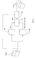
- the frame FRM i.e., an interlaced video image
- a spatial-de-interlacing module SP which implements the improved non-motion-compensated digital-image de-interlacing procedure described previously with reference to Figure 3
- a temporal-de-interlacing module TMP which implements the improved motion-compensated digital-image de-interlacing procedure described previously with reference to Figures 4 and 5.
- the spatial-de-interlacing module SP supplies at output a spatial reconstruction Tsp
- the temporal-de-interlacing module TMP supplies at output a backward temporal reconstruction Tub, given by the unidirectional estimation on the preceding field or backward field
- a forward temporal reconstruction Tuf given by the unidirectional estimation on the subsequent field or forward field
- a balanced temporal reconstruction Tbb given by the balanced bi-directional estimation
- a non-balanced temporal reconstruction Tbn given by the non-balanced bi-directional estimation.
- a decision module D receives the corresponding spatial reconstruction Tsp and the temporal reconstructions Tub, Tuf, Tbb and Tbn.
- the variance of the block being examined may, for example, be chosen.
- a median filter i.e., a filter that, given a set of values, returns the value that occupies the intermediate position in said set of values.
- the median of the set of values (10, 80, 20) is 20; the median of the set of values (10, 80, 20, 30) is 25, which is the mean of the two intermediate values 20 and 30.
- the decision module D there is chosen, as best reconstructed block BK for composing the reconstructed image RINT, the block that corresponds to the median of the variances of the individual spatial and temporal predictors.
- This operation of reconstruction is carried out by means of an appropriate reconstruction module RC set at the output of the decision module D.
- the reconstruction module RC receives, from the decision module D, the blocks BK chosen by means of the median filter and recomposes the field to be reconstructed MFD. Moreover, this reconstruction module RC receives at input the frame FRM, in such a way as to be able to supply at output the reconstructed image RINT with the fields arranged in an ordered way for a progressive-scan display.
- the de-interlacing method described guarantees optimal performance in all the situations that can occur during processing of a video sequence, it being able to choose from time to time the technique that produces the best reconstruction. This is obtained by carrying out in an appropriate decision module, operations of application of convenient cost and choice functions, so as to prevent defects of formation of blocks from arising in the reconstructed image.
- the procedure proposed can be applied indifferently both to the European television system PAL and to the American television system NTSC, as well as to high-definition TV.
Abstract
Description
- motion-compensated procedures; and
- non-motion-compensated procedures.

- Figure 1 and Figure 2, which correspond to the known art, have already been described previously;
- Figure 3 illustrates a diagram corresponding to an operation of a procedure of spatial de-interlacing comprised in the method according to the invention;
- Figure 4 illustrates a diagram corresponding to an operation of a procedure of temporal de-interlacing comprised in the method according to the invention;
- Figure 5 illustrates a diagram corresponding to an operation of a procedure of temporal de-interlacing comprised in the method according to the invention; and
- Figure 6 illustrates a schematic circuit diagram of a de-interlacing system implementing the method according to the invention.
- an operation of extension of the work window;
- operations designed to obtain a sub-pixel degree of precision;
- an operation of adaptive sizing of the work window; and
- an operation of post-processing and final filtering of the spatial reconstruction.

- if the first pixel to be reconstructed X1 has been reconstructed using the pair of original pixels corresponding to the vertical direction, then P2 = P1 - 1;
- if the first pixel to be reconstructed X1 has been reconstructed using the pair of original pixels corresponding to the steepest slope possible (both towards the right and towards the left), then P2 = P1 + 1;
- in all the other cases, P2 = P1;
- in any case, it must be always P2≥3 and P2 ≤ Pmax, where Pmax indicates a maximum number of pixels determined a priori.
- an operation of testing of a number Q of vectors temporally and spatially preceding the one referring to the current macroblock, with final choice of the best vector; and
- an operation of application of a refining grid, made up of R points, in the neighbourhood of the position pointed by the best vector found in the preceding step.

Claims (16)
- A method for de-interlacing digital images, comprising a procedure of spatial de-interlacing applied to a digital image (FRM) to obtain a spatial reconstruction (Tsp), characterized in that it further comprises the operations of:applying, to said digital image (FRM), one or more de-interlacing procedures of a temporal type to obtain one or more temporal reconstructions (Tub, Tuf, Tbb and Tbn); andselecting from among one of said spatial reconstructions (Tsp) and said one or more temporal reconstructions (Tub, Tuf, Tbb and Tbn), said operation of selection comprising the operations of applying a cost function (var) to said spatial reconstruction (Tsp) and temporal reconstructions (Tub, Tuf, Tbb and Tbn) and choosing from among said spatial reconstruction (Tsp) and temporal reconstructions (Tub, Tuf, Tbb and Tbn) the reconstruction that minimizes said cost function (var).
- The method according to Claim 1, characterized in that said spatial reconstruction (Tsp) and said one or more temporal reconstructions (Tub, Tuf, Tbb and Tbn) correspond to each block (BK) to be reconstructed of a field to be reconstructed (MFD) of said digital image (FRM).
- The method according to Claim 1 or Claim 2, characterized in that said cost function (var) is the variance of said spatial reconstruction (Tsp) and said temporal reconstructions (Tub, Tuf, Tbb and Tbn) on said block (BK) to be reconstructed.
- The method according to any one of Claims 1 to 3, characterized in that said operation of choosing, from among said spatial reconstruction (Tsp) and said temporal reconstructions (Tub, Tuf, Tbb and Tbn), the reconstruction that minimizes said cost function (var) is obtained by applying a median-filter function.
- The method according to any one of Claims 1 to 4, characterized in that said procedure of spatial de-interlacing provides for operating on a work window (FL) of pixels of said digital image (FRM) adjacent to a pixel (X) to be reconstructed by performing an operation of linear interpolation on pairs of pixels belonging to said work window (FL), and in that said procedure further comprises the following operations:an operation of extension of the work window (FL) to a number of adjacent or near pixels greater than or equal to three; andan operation of adaptive sizing of said work window (FL).
- The method according to Claim 5, characterized in that the operation of adaptive sizing of said work window (FL) provides for varying in an adaptive way a number (P) of pairs of pixels that are considered each time for the operation of linear interpolation.
- The method according to Claim 6, characterized in that said operation of varying in an adaptive way comprises the steps of:using a first number (P1) of pairs of pixels for reconstructing a first pixel (X1); andusing for reconstructing a second pixel (X2) a work window that comprises a second number (P2) of pairs of pixels, the second number (P2) of pairs of pixels being determined starting from the first number (P1) of pairs of pixels according to the following criteria:if the first pixel (X1) has been reconstructed using a pair of pixels corresponding to the vertical direction, then the second number (P2) of pairs of pixels is equal to the first number (P1) of pixels minus one;if the first pixel (X1) has been reconstructed using the pair of original pixels corresponding to the steepest slope possible, then the second number (P2) of pairs of pixels is equal to the first number (P1) of pairs of pixels plus one;in all the other cases, the second number (P2) of pairs of pixels is equal to the first number (P1); andin any case, the second number (P2) of pairs of pixels must be greater than or equal to three and smaller than or equal to a maximum number of pairs of pixels determined a priori (Pmax).
- The method according to any one of Claims 1 to 7, characterized in that said spatial de-interlacing procedure further comprises operations suitable for obtaining a sub-pixel degree of precision.
- The method according to any one of Claims 1 to 8, characterized in that said procedure of spatial de-interlacing comprises an operation of post-processing and final filtering of the spatial reconstruction (Tsp).
- The method according to Claim 9, characterized in that said operation of post-processing and final filtering of the spatial reconstruction (Tsp) is varied dynamically (f1, f2) according to a degree of correlation with the reconstructed pixel (X).
- The method according to any one of Claims 1 to 10, characterized in that said procedure of de-interlacing of a temporal type provides for reconstructing the field to be reconstructed (MFD) of the digital image (FRM) by means of an operation of decomposition into blocks (BK) to be reconstructed, and reconstructing by interpolation the blocks (BKn, BKm) belonging to a preceding field (n) and a subsequent field (m), minimizing a correlation function, said procedure further comprising the following operations:an operation of testing of a number (Q) of motion vectors (MV, -MV; MV1, MV2) temporally and spatially preceding the one that refers to the block (BK) to be reconstructed, with final choice of the best vector;an operation of application of a refining grid (R) in the neighbourhood of the position pointed by the best vector found in the preceding operation; anda final operation of choice of the best position.
- The method according to Claim 11, characterized in that said temporal de-interlacing procedure comprises a procedure of non-balanced estimation, which moreover comprises the operations of:generating, during said testing operation, a first vector (MV1) that points to the preceding field (n) and a second vector (MV2) that points to the subsequent field (m) with respect to the field to be reconstructed (MFD) of the digital image (FRM); andobtaining said first vector (MV1) and said second vector (MV2) by applying, during said operation of application of a refining grid (R), a first grid corresponding to the preceding field (n) and a second grid corresponding to the subsequent field (m).
- The method according to Claim 11 or Claim 12, characterized in that said procedure of temporal de-interlacing comprises a procedure of unidirectional estimation, which further comprises the operation of reconstructing the current block (BK) starting from just the preceding field (n) or, respectively, the subsequent field (m) by performing said operations of testing and of application of a grid on a block (BK) belonging to the preceding field (n) or, respectively, the subsequent field (m) and on a block (BKh) belonging to the current field of parity (h) opposite to that of the field to be reconstructed (MFD).
- A system for de-interlacing digital images implementing the method according to any one of Claims 1 to 13, characterized in that it comprises a module for implementing said procedure of spatial de-interlacing (SP) and a module for implementing said procedure of temporal de-interlacing (TMP), set in parallel with respect to an input constituted by the digital image (FRM), and in that a decision module (D) receives in parallel the reconstructions (Tsp; Tub, Tuf, Tbb and Tbn) of said spatial module (SP) and temporal module (TMP), said decision module (D) being suitable for applying the cost functions (var) and choice functions for minimizing said cost functions.
- The de-interlacing system according to Claim 14, characterized in that downstream of said decision module (D) a reconstruction module (RC) is placed that receives at input the blocks (BK) chosen by said decision module and the digital image (FRM) for composing a reconstructed image (RINT) for progressive-scanning screens.
- A computer product directly loadable into the memory of a digital computer and comprising software code portions for performing the method according to any one of Claims 1 to 13 when the product is run on a computer.
Priority Applications (4)
| Application Number | Priority Date | Filing Date | Title |
|---|---|---|---|
| DE60312981T DE60312981D1 (en) | 2003-08-26 | 2003-08-26 | Method and system for canceling the interlacing process during the presentation of video images |
| EP03425560A EP1511311B1 (en) | 2003-08-26 | 2003-08-26 | Method and system for de-interlacing digital images, and computer program product therefor |
| US10/925,884 US7375763B2 (en) | 2003-08-26 | 2004-08-24 | Method and system for de-interlacing digital images, and computer program product therefor |
| US11/041,518 US7663695B2 (en) | 2000-05-05 | 2005-01-21 | Method and system for de-interlacing digital images, and computer program product therefor |
Applications Claiming Priority (1)
| Application Number | Priority Date | Filing Date | Title |
|---|---|---|---|
| EP03425560A EP1511311B1 (en) | 2003-08-26 | 2003-08-26 | Method and system for de-interlacing digital images, and computer program product therefor |
Publications (2)
| Publication Number | Publication Date |
|---|---|
| EP1511311A1 true EP1511311A1 (en) | 2005-03-02 |
| EP1511311B1 EP1511311B1 (en) | 2007-04-04 |
Family
ID=34089793
Family Applications (1)
| Application Number | Title | Priority Date | Filing Date |
|---|---|---|---|
| EP03425560A Expired - Fee Related EP1511311B1 (en) | 2000-05-05 | 2003-08-26 | Method and system for de-interlacing digital images, and computer program product therefor |
Country Status (3)
| Country | Link |
|---|---|
| US (1) | US7375763B2 (en) |
| EP (1) | EP1511311B1 (en) |
| DE (1) | DE60312981D1 (en) |
Cited By (1)
| Publication number | Priority date | Publication date | Assignee | Title |
|---|---|---|---|---|
| WO2007075885A3 (en) * | 2005-12-21 | 2007-10-25 | Analog Device Inc | Methods and apparatus for progressive scanning of interlaced video |
Families Citing this family (16)
| Publication number | Priority date | Publication date | Assignee | Title |
|---|---|---|---|---|
| US7663695B2 (en) * | 2000-05-05 | 2010-02-16 | Stmicroelectronics S.R.L. | Method and system for de-interlacing digital images, and computer program product therefor |
| WO2005022922A1 (en) * | 2003-09-02 | 2005-03-10 | Koninklijke Philips Electronics N.V. | Temporal interpolation of a pixel on basis of occlusion detection |
| WO2005025213A1 (en) * | 2003-09-04 | 2005-03-17 | Koninklijke Philips Electronics N.V. | Robust de-interlacing of video signals |
| KR101127220B1 (en) * | 2004-07-28 | 2012-04-12 | 세종대학교산학협력단 | Apparatus for motion compensation-adaptive de-interlacing and method the same |
| TWI280798B (en) * | 2004-09-22 | 2007-05-01 | Via Tech Inc | Apparatus and method of adaptive de-interlace of image |
| US7620241B2 (en) * | 2004-11-30 | 2009-11-17 | Hewlett-Packard Development Company, L.P. | Artifact reduction in a digital video |
| JP4736456B2 (en) * | 2005-02-15 | 2011-07-27 | 株式会社日立製作所 | Scanning line interpolation device, video display device, video signal processing device |
| US7952643B2 (en) * | 2006-03-30 | 2011-05-31 | Intel Corporation | Pipelining techniques for deinterlacing video information |
| EP1931136B1 (en) * | 2006-12-08 | 2016-04-20 | Panasonic Intellectual Property Corporation of America | Block-based line combination algorithm for de-interlacing |
| JP4181598B2 (en) * | 2006-12-22 | 2008-11-19 | シャープ株式会社 | Image display apparatus and method, image processing apparatus and method |
| DE102007015002A1 (en) * | 2007-03-28 | 2008-10-02 | Micronas Gmbh | Iterative method for interpolation of image information values |
| US8237859B2 (en) * | 2007-09-14 | 2012-08-07 | Himax Technologies Limited | Method for video conversion of video stream and apparatus thereof |
| JP4343255B1 (en) * | 2008-06-25 | 2009-10-14 | 株式会社東芝 | Image expansion apparatus and image expansion method |
| US8125524B2 (en) | 2008-12-12 | 2012-02-28 | Nxp B.V. | System and method for the detection of de-interlacing of scaled video |
| US9002086B2 (en) * | 2009-05-07 | 2015-04-07 | Koninklijke Philips N.V. | System and method for generating a tomographic reconstruction filter |
| US10674045B2 (en) * | 2017-05-31 | 2020-06-02 | Google Llc | Mutual noise estimation for videos |
Citations (7)
| Publication number | Priority date | Publication date | Assignee | Title |
|---|---|---|---|---|
| US5546130A (en) * | 1993-10-11 | 1996-08-13 | Thomson Consumer Electronics S.A. | Method and apparatus for forming a video signal using motion estimation and signal paths with different interpolation processing |
| EP0735748A2 (en) * | 1995-03-27 | 1996-10-02 | AT&T Corp. | Method and apparatus for converting an interlaced video frame sequence into a progressively-scanned sequence |
| US5784114A (en) * | 1992-07-03 | 1998-07-21 | Snell & Wilcox Ltd | Motion compensated video processing |
| US5936676A (en) * | 1997-08-21 | 1999-08-10 | Miranda Technologies Inc. | Apparatus and method for line interpolating an interlaced video signal |
| US6442203B1 (en) * | 1999-11-05 | 2002-08-27 | Demografx | System and method for motion compensation and frame rate conversion |
| US20020171759A1 (en) * | 2001-02-08 | 2002-11-21 | Handjojo Benitius M. | Adaptive interlace-to-progressive scan conversion algorithm |
| US20030048278A1 (en) * | 2001-06-19 | 2003-03-13 | Jin Ji | Motion adaptive de-interlacing circuit and method |
Family Cites Families (28)
| Publication number | Priority date | Publication date | Assignee | Title |
|---|---|---|---|---|
| US5689305A (en) * | 1994-05-24 | 1997-11-18 | Kabushiki Kaisha Toshiba | System for deinterlacing digitally compressed video and method |
| KR0126871B1 (en) | 1994-07-30 | 1997-12-29 | 심상철 | HIGH SPEED BMA FOR Bi-DIRECTIONAL MOVING VECTOR ESTIMATION |
| KR0171146B1 (en) | 1995-03-18 | 1999-03-20 | 배순훈 | Feature point based motion vectors detecting apparatus |
| US5703966A (en) * | 1995-06-27 | 1997-12-30 | Intel Corporation | Block selection using motion estimation error |
| US5668608A (en) | 1995-07-26 | 1997-09-16 | Daewoo Electronics Co., Ltd. | Motion vector estimation method and apparatus for use in an image signal encoding system |
| US5745183A (en) | 1995-08-25 | 1998-04-28 | Thomson Consumer Electronics, Inc. | Image motion estimation system which derives candidate block from interpolated motion vectors |
| DE19548451C1 (en) * | 1995-12-22 | 1997-02-20 | Siemens Ag | Computer-assisted movement estimation system for video sequence images |
| KR0176568B1 (en) | 1996-01-27 | 1999-05-01 | 김광호 | Device and method for conversion interlaced to progressive scanning |
| JP3774954B2 (en) | 1996-10-30 | 2006-05-17 | 株式会社日立製作所 | Video encoding method |
| US6262773B1 (en) | 1997-09-15 | 2001-07-17 | Sharp Laboratories Of America, Inc. | System for conversion of interlaced video to progressive video using edge correlation |
| US6014181A (en) | 1997-10-13 | 2000-01-11 | Sharp Laboratories Of America, Inc. | Adaptive step-size motion estimation based on statistical sum of absolute differences |
| US6331874B1 (en) | 1999-06-29 | 2001-12-18 | Lsi Logic Corporation | Motion compensated de-interlacing |
| KR100303728B1 (en) * | 1999-07-29 | 2001-09-29 | 구자홍 | Deinterlacing method of interlaced scanning video |
| KR100327395B1 (en) * | 1999-09-03 | 2002-03-13 | 구자홍 | Deinterlacing method based on motion-compensated inter-field interpolation |
| WO2001074070A2 (en) * | 2000-03-29 | 2001-10-04 | Mti Film Llc | Format conversion |
| EP1152621A1 (en) * | 2000-05-05 | 2001-11-07 | STMicroelectronics S.r.l. | Motion estimation process and system. |
| US7663695B2 (en) * | 2000-05-05 | 2010-02-16 | Stmicroelectronics S.R.L. | Method and system for de-interlacing digital images, and computer program product therefor |
| US6414719B1 (en) * | 2000-05-26 | 2002-07-02 | Sarnoff Corporation | Motion adaptive median filter for interlace to progressive scan conversion |
| KR100708091B1 (en) * | 2000-06-13 | 2007-04-16 | 삼성전자주식회사 | Frame rate converter using bidirectional motion vector and method thereof |
| US6661464B1 (en) * | 2000-11-21 | 2003-12-09 | Dell Products L.P. | Dynamic video de-interlacing |
| US7095445B2 (en) | 2000-12-20 | 2006-08-22 | Samsung Electronics Co., Ltd. | Method of detecting motion in an interlaced video sequence based on logical operation on linearly scaled motion information and motion detection apparatus |
| KR100393066B1 (en) * | 2001-06-11 | 2003-07-31 | 삼성전자주식회사 | Apparatus and method for adaptive motion compensated de-interlacing video data using adaptive compensated olation and method thereof |
| EP1267575B1 (en) * | 2001-06-14 | 2006-11-29 | STMicroelectronics S.r.l. | A method for converting the scanning format of images, a system and computer program product therefor |
| US6992725B2 (en) * | 2001-10-22 | 2006-01-31 | Nec Electronics America, Inc. | Video data de-interlacing using perceptually-tuned interpolation scheme |
| US7154556B1 (en) * | 2002-03-21 | 2006-12-26 | Pixelworks, Inc. | Weighted absolute difference based deinterlace method and apparatus |
| JP3898546B2 (en) * | 2002-03-27 | 2007-03-28 | 株式会社東芝 | Image scanning conversion method and apparatus |
| KR100902315B1 (en) * | 2002-07-25 | 2009-06-12 | 삼성전자주식회사 | Apparatus and method for deinterlacing |
| US7075581B1 (en) * | 2003-06-03 | 2006-07-11 | Zoran Corporation | Interlaced-to-progressive scan conversion based on film source detection |
-
2003
- 2003-08-26 DE DE60312981T patent/DE60312981D1/en not_active Expired - Lifetime
- 2003-08-26 EP EP03425560A patent/EP1511311B1/en not_active Expired - Fee Related
-
2004
- 2004-08-24 US US10/925,884 patent/US7375763B2/en active Active
Patent Citations (7)
| Publication number | Priority date | Publication date | Assignee | Title |
|---|---|---|---|---|
| US5784114A (en) * | 1992-07-03 | 1998-07-21 | Snell & Wilcox Ltd | Motion compensated video processing |
| US5546130A (en) * | 1993-10-11 | 1996-08-13 | Thomson Consumer Electronics S.A. | Method and apparatus for forming a video signal using motion estimation and signal paths with different interpolation processing |
| EP0735748A2 (en) * | 1995-03-27 | 1996-10-02 | AT&T Corp. | Method and apparatus for converting an interlaced video frame sequence into a progressively-scanned sequence |
| US5936676A (en) * | 1997-08-21 | 1999-08-10 | Miranda Technologies Inc. | Apparatus and method for line interpolating an interlaced video signal |
| US6442203B1 (en) * | 1999-11-05 | 2002-08-27 | Demografx | System and method for motion compensation and frame rate conversion |
| US20020171759A1 (en) * | 2001-02-08 | 2002-11-21 | Handjojo Benitius M. | Adaptive interlace-to-progressive scan conversion algorithm |
| US20030048278A1 (en) * | 2001-06-19 | 2003-03-13 | Jin Ji | Motion adaptive de-interlacing circuit and method |
Cited By (1)
| Publication number | Priority date | Publication date | Assignee | Title |
|---|---|---|---|---|
| WO2007075885A3 (en) * | 2005-12-21 | 2007-10-25 | Analog Device Inc | Methods and apparatus for progressive scanning of interlaced video |
Also Published As
| Publication number | Publication date |
|---|---|
| US20050110901A1 (en) | 2005-05-26 |
| EP1511311B1 (en) | 2007-04-04 |
| US7375763B2 (en) | 2008-05-20 |
| DE60312981D1 (en) | 2007-05-16 |
Similar Documents
| Publication | Publication Date | Title |
|---|---|---|
| US7663695B2 (en) | Method and system for de-interlacing digital images, and computer program product therefor | |
| EP1511311B1 (en) | Method and system for de-interlacing digital images, and computer program product therefor | |
| US6118488A (en) | Method and apparatus for adaptive edge-based scan line interpolation using 1-D pixel array motion detection | |
| US6473460B1 (en) | Method and apparatus for calculating motion vectors | |
| EP1223748B1 (en) | Motion detection in an interlaced video signal | |
| EP1164792A2 (en) | Format converter using bidirectional motion vector and method thereof | |
| EP1158792A2 (en) | Filter for deinterlacing a video signal | |
| US20020171759A1 (en) | Adaptive interlace-to-progressive scan conversion algorithm | |
| JP4153480B2 (en) | Noise attenuator and progressive scan converter | |
| US7787048B1 (en) | Motion-adaptive video de-interlacer | |
| EP1832112A2 (en) | Spatio-temporal adaptive video de-interlacing | |
| KR100484182B1 (en) | Apparatus and method for deinterlacing | |
| JP3619542B2 (en) | Motion correction video signal processing apparatus and method | |
| KR20070030223A (en) | Pixel interpolation | |
| US20050219408A1 (en) | Apparatus to suppress artifacts of an image signal and method thereof | |
| US20120288001A1 (en) | Motion vector refining apparatus | |
| KR100540380B1 (en) | Apparatus and method for intra field interpolation of deinterlacer | |
| Phu et al. | A median based interpolation algorithm for deinterlacing | |
| US20060176394A1 (en) | De-interlacing of video data | |
| US20030184676A1 (en) | Image scan conversion method and apparatus | |
| Lee et al. | A motion-adaptive deinterlacer via hybrid motion detection and edge-pattern recognition | |
| KR101513395B1 (en) | A motion adaptive deinterlacing system | |
| KR101144435B1 (en) | Methods of edge-based deinterlacing using weight and image processing devices using the same | |
| KR101204210B1 (en) | Methods of deinterlacing using geometric duality and image processing device using the same | |
| KR100616164B1 (en) | Apparatus and method for de-interlacing adaptively field image by using median filter |
Legal Events
| Date | Code | Title | Description |
|---|---|---|---|
| PUAI | Public reference made under article 153(3) epc to a published international application that has entered the european phase |
Free format text: ORIGINAL CODE: 0009012 |
|
| AK | Designated contracting states |
Kind code of ref document: A1 Designated state(s): AT BE BG CH CY CZ DE DK EE ES FI FR GB GR HU IE IT LI LU MC NL PT RO SE SI SK TR |
|
| AX | Request for extension of the european patent |
Extension state: AL LT LV MK |
|
| RIN1 | Information on inventor provided before grant (corrected) |
Inventor name: PAU, DANILO Inventor name: SCHIAVONE, ANGELO Inventor name: PRIVITERA, ELIO Inventor name: ALFONSO, DANIELE |
|
| 17P | Request for examination filed |
Effective date: 20050502 |
|
| 17Q | First examination report despatched |
Effective date: 20050613 |
|
| AKX | Designation fees paid |
Designated state(s): DE FR GB IT |
|
| GRAP | Despatch of communication of intention to grant a patent |
Free format text: ORIGINAL CODE: EPIDOSNIGR1 |
|
| GRAS | Grant fee paid |
Free format text: ORIGINAL CODE: EPIDOSNIGR3 |
|
| GRAA | (expected) grant |
Free format text: ORIGINAL CODE: 0009210 |
|
| AK | Designated contracting states |
Kind code of ref document: B1 Designated state(s): DE FR GB IT |
|
| REG | Reference to a national code |
Ref country code: GB Ref legal event code: FG4D |
|
| REF | Corresponds to: |
Ref document number: 60312981 Country of ref document: DE Date of ref document: 20070516 Kind code of ref document: P |
|
| EN | Fr: translation not filed | ||
| PLBE | No opposition filed within time limit |
Free format text: ORIGINAL CODE: 0009261 |
|
| STAA | Information on the status of an ep patent application or granted ep patent |
Free format text: STATUS: NO OPPOSITION FILED WITHIN TIME LIMIT |
|
| 26N | No opposition filed |
Effective date: 20080107 |
|
| PG25 | Lapsed in a contracting state [announced via postgrant information from national office to epo] |
Ref country code: DE Free format text: LAPSE BECAUSE OF FAILURE TO SUBMIT A TRANSLATION OF THE DESCRIPTION OR TO PAY THE FEE WITHIN THE PRESCRIBED TIME-LIMIT Effective date: 20070705 Ref country code: FR Free format text: LAPSE BECAUSE OF FAILURE TO SUBMIT A TRANSLATION OF THE DESCRIPTION OR TO PAY THE FEE WITHIN THE PRESCRIBED TIME-LIMIT Effective date: 20071130 |
|
| PG25 | Lapsed in a contracting state [announced via postgrant information from national office to epo] |
Ref country code: FR Free format text: LAPSE BECAUSE OF FAILURE TO SUBMIT A TRANSLATION OF THE DESCRIPTION OR TO PAY THE FEE WITHIN THE PRESCRIBED TIME-LIMIT Effective date: 20070404 |
|
| PGFP | Annual fee paid to national office [announced via postgrant information from national office to epo] |
Ref country code: GB Payment date: 20110728 Year of fee payment: 9 |
|
| PGFP | Annual fee paid to national office [announced via postgrant information from national office to epo] |
Ref country code: IT Payment date: 20110723 Year of fee payment: 9 |
|
| GBPC | Gb: european patent ceased through non-payment of renewal fee |
Effective date: 20120826 |
|
| PG25 | Lapsed in a contracting state [announced via postgrant information from national office to epo] |
Ref country code: IT Free format text: LAPSE BECAUSE OF NON-PAYMENT OF DUE FEES Effective date: 20120826 |
|
| PG25 | Lapsed in a contracting state [announced via postgrant information from national office to epo] |
Ref country code: GB Free format text: LAPSE BECAUSE OF NON-PAYMENT OF DUE FEES Effective date: 20120826 |