EP1511251A2 - Device for sending electronic mail - Google Patents
Device for sending electronic mail Download PDFInfo
- Publication number
- EP1511251A2 EP1511251A2 EP04255213A EP04255213A EP1511251A2 EP 1511251 A2 EP1511251 A2 EP 1511251A2 EP 04255213 A EP04255213 A EP 04255213A EP 04255213 A EP04255213 A EP 04255213A EP 1511251 A2 EP1511251 A2 EP 1511251A2
- Authority
- EP
- European Patent Office
- Prior art keywords
- file
- electronic mail
- unit
- location
- transmitting
- Prior art date
- Legal status (The legal status is an assumption and is not a legal conclusion. Google has not performed a legal analysis and makes no representation as to the accuracy of the status listed.)
- Ceased
Links
- 238000012545 processing Methods 0.000 claims description 43
- 238000004590 computer program Methods 0.000 claims 3
- 238000012546 transfer Methods 0.000 description 33
- 238000000034 method Methods 0.000 description 27
- 230000010365 information processing Effects 0.000 description 24
- 230000006870 function Effects 0.000 description 23
- 230000005540 biological transmission Effects 0.000 description 22
- 230000008569 process Effects 0.000 description 15
- 238000004891 communication Methods 0.000 description 13
- 101100048435 Caenorhabditis elegans unc-18 gene Proteins 0.000 description 7
- 238000007639 printing Methods 0.000 description 7
- 230000003287 optical effect Effects 0.000 description 5
- 230000009471 action Effects 0.000 description 4
- 238000010586 diagram Methods 0.000 description 4
- 238000002360 preparation method Methods 0.000 description 3
- 238000006243 chemical reaction Methods 0.000 description 2
- 238000005516 engineering process Methods 0.000 description 2
- 230000000977 initiatory effect Effects 0.000 description 2
- 238000003780 insertion Methods 0.000 description 2
- 230000037431 insertion Effects 0.000 description 2
- 230000003213 activating effect Effects 0.000 description 1
- 230000015556 catabolic process Effects 0.000 description 1
- 239000003086 colorant Substances 0.000 description 1
- 239000002131 composite material Substances 0.000 description 1
- 238000010276 construction Methods 0.000 description 1
- 238000006731 degradation reaction Methods 0.000 description 1
- 230000006872 improvement Effects 0.000 description 1
- 238000012905 input function Methods 0.000 description 1
- 239000004973 liquid crystal related substance Substances 0.000 description 1
- 238000012986 modification Methods 0.000 description 1
- 230000004048 modification Effects 0.000 description 1
- 239000013307 optical fiber Substances 0.000 description 1
- 108091008695 photoreceptors Proteins 0.000 description 1
- 238000013139 quantization Methods 0.000 description 1
- 239000004065 semiconductor Substances 0.000 description 1
- GGCZERPQGJTIQP-UHFFFAOYSA-N sodium;9,10-dioxoanthracene-2-sulfonic acid Chemical compound [Na+].C1=CC=C2C(=O)C3=CC(S(=O)(=O)O)=CC=C3C(=O)C2=C1 GGCZERPQGJTIQP-UHFFFAOYSA-N 0.000 description 1
- 238000005092 sublimation method Methods 0.000 description 1
- 230000001360 synchronised effect Effects 0.000 description 1
Images





Classifications
-
- H—ELECTRICITY
- H04—ELECTRIC COMMUNICATION TECHNIQUE
- H04N—PICTORIAL COMMUNICATION, e.g. TELEVISION
- H04N1/00—Scanning, transmission or reproduction of documents or the like, e.g. facsimile transmission; Details thereof
- H04N1/32—Circuits or arrangements for control or supervision between transmitter and receiver or between image input and image output device, e.g. between a still-image camera and its memory or between a still-image camera and a printer device
- H04N1/32358—Circuits or arrangements for control or supervision between transmitter and receiver or between image input and image output device, e.g. between a still-image camera and its memory or between a still-image camera and a printer device using picture signal storage, e.g. at transmitter
- H04N1/324—Circuits or arrangements for control or supervision between transmitter and receiver or between image input and image output device, e.g. between a still-image camera and its memory or between a still-image camera and a printer device using picture signal storage, e.g. at transmitter intermediate the transmitter and receiver terminals, e.g. at an exchange
- H04N1/32432—Circuits or arrangements for control or supervision between transmitter and receiver or between image input and image output device, e.g. between a still-image camera and its memory or between a still-image camera and a printer device using picture signal storage, e.g. at transmitter intermediate the transmitter and receiver terminals, e.g. at an exchange in a particular memory file for retrieval by the user, e.g. in a facsimile mailbox
- H04N1/32438—Informing the addressee of reception
-
- H—ELECTRICITY
- H04—ELECTRIC COMMUNICATION TECHNIQUE
- H04L—TRANSMISSION OF DIGITAL INFORMATION, e.g. TELEGRAPHIC COMMUNICATION
- H04L51/00—User-to-user messaging in packet-switching networks, transmitted according to store-and-forward or real-time protocols, e.g. e-mail
- H04L51/07—User-to-user messaging in packet-switching networks, transmitted according to store-and-forward or real-time protocols, e.g. e-mail characterised by the inclusion of specific contents
- H04L51/08—Annexed information, e.g. attachments
-
- H—ELECTRICITY
- H04—ELECTRIC COMMUNICATION TECHNIQUE
- H04N—PICTORIAL COMMUNICATION, e.g. TELEVISION
- H04N1/00—Scanning, transmission or reproduction of documents or the like, e.g. facsimile transmission; Details thereof
- H04N1/00127—Connection or combination of a still picture apparatus with another apparatus, e.g. for storage, processing or transmission of still picture signals or of information associated with a still picture
- H04N1/00204—Connection or combination of a still picture apparatus with another apparatus, e.g. for storage, processing or transmission of still picture signals or of information associated with a still picture with a digital computer or a digital computer system, e.g. an internet server
-
- H—ELECTRICITY
- H04—ELECTRIC COMMUNICATION TECHNIQUE
- H04N—PICTORIAL COMMUNICATION, e.g. TELEVISION
- H04N1/00—Scanning, transmission or reproduction of documents or the like, e.g. facsimile transmission; Details thereof
- H04N1/00127—Connection or combination of a still picture apparatus with another apparatus, e.g. for storage, processing or transmission of still picture signals or of information associated with a still picture
- H04N1/00204—Connection or combination of a still picture apparatus with another apparatus, e.g. for storage, processing or transmission of still picture signals or of information associated with a still picture with a digital computer or a digital computer system, e.g. an internet server
- H04N1/00244—Connection or combination of a still picture apparatus with another apparatus, e.g. for storage, processing or transmission of still picture signals or of information associated with a still picture with a digital computer or a digital computer system, e.g. an internet server with a server, e.g. an internet server
-
- H—ELECTRICITY
- H04—ELECTRIC COMMUNICATION TECHNIQUE
- H04N—PICTORIAL COMMUNICATION, e.g. TELEVISION
- H04N2201/00—Indexing scheme relating to scanning, transmission or reproduction of documents or the like, and to details thereof
- H04N2201/0077—Types of the still picture apparatus
- H04N2201/0094—Multifunctional device, i.e. a device capable of all of reading, reproducing, copying, facsimile transception, file transception
Definitions
- the present invention relates to a technology for sending/receiving electronic mails.
- Japanese Patent Application Laid-Open Publication No. 2003-134296 discloses a technique for sending electronic mails with files as attachments.
- SMTP Simple Mail Transfer Protocol
- mail servers send and receive every piece of mail to and from each other. Therefore, if the volume of the attached file is large, large load is put on the electronic mail systems, and the electronic mail systems may crash or become slow. To avoid this, there is a tendency to impose limitations on the volume of an attachment. It that case, the sender is required to divide a large-volume data into two or more pieces and the receiver the required to combine the pieces.
- FTP File Transfer Protocol
- FTP server Internet server
- the file when sending an electronic file to a receiver, the file is transmitted to a predetermined location. Then, an electronic mail is created and sent to the receiver. This electronic mail contains information that makes it possible for the receiver to download the file from the location. Finally, the electronic mail created is sent to the receiver without attaching the file.
- the present embodiment in an example in which composite functions such as a copy function, a facsimile (FAX) function, a printing function, a scanning function and a function to deliver an input image (an original image read out by the scanning function and an image input by the printing or FAX function) are applied to a so-called digital color multifunction product as an information processor.
- composite functions such as a copy function, a facsimile (FAX) function, a printing function, a scanning function and a function to deliver an input image (an original image read out by the scanning function and an image input by the printing or FAX function) are applied to a so-called digital color multifunction product as an information processor.
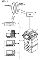
- Fig. 1 is a block diagram of a system that includes a digital color multifunction product 1 according to an embodiment of the present embodiment.
- a system in which a server computer 3 to execute various kinds of information processing and a plurality of client computers 4 are connected to the digital multifunction product 1 via local-area networks 2 (LAN) serving as a communication network is assumed in the present embodiment.
- the server computer 3 for example, supports the File Transfer Protocol (FTP) and the Hypertext Transfer Protocol (HTTP), and realizes the functions of Web server and Domain Name Server (DNS).
- FTP File Transfer Protocol
- HTTP Hypertext Transfer Protocol
- DNS Domain Name Server
- This system is connected to an Internet network 6 via a communication controlling unit 5 and configured so as to allow data communications to external environments via the Internet network 6.
- a router, a switching system, a modem, a data set level (DSL) modem or the like is typical of the communication controlling unit 5, and anyone of them may be acceptable as long as it is at least capable of one of Transmission Control Protocol (TCP) and Internet Protocol (IP) communications.
- the LAN 2 is not limited to cable communication but radio communication (infrared rays, radio waves and so on) may be acceptable.
- the LAN 2 may employ optical fiber.
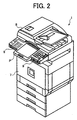
- Fig. 2 is an external perspective of the digital color multifunction product 1.
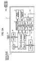
- Fig. 3 is a block diagram of the digital color multifunction product 1.
- the digital color multifunction product 1 is configured by providing an image scanner 8 to read out an image of an original mounted on the upper portion of a document printer 7 that is an image forming apparatus to form an image on a medium such as transfer paper.
- an operation panel P capable of showing a display to an operator and accepting a variety of inputs such as function settings set by the operator is provided on the exterior of the image scanner 8.
- an external medium input/output device 9 that is a device to read out program codes, image data and the like stored on a storage medium M (see Fig. 3) such as optical disk, flexible disk, and to write program codes, image data and the like on the storage medium M is provided on the lower portion of the operation panel P with an insertion inlet exposed outside to accept insertion of the storage medium M.
- the structure of such a digital color multifunction product 1 is largely divided into an image processing unit A and an information processing unit B as shown in Fig. 3.
- the document printer 7 and the image scanner 8 belong to the image processing unit A and the operation panel P and the external medium input/output device 9 belong to the information processing unit B.
- the image processing unit A is explained next.
- the image processing unit A provided with the document printer 7 and image scanner 8 is provided with an image processing controlling unit 10 to control the whole image processing in the image processing unit A.
- an image processing controlling unit 10 to control the whole image processing in the image processing unit A.
- a print controlling unit 11 to control the document printer 7 and an image reader controlling unit 12 to control the image scanner 8 are connected.
- the print controlling unit 11 outputs a print command including image data to the document printer 7 according to the control of the image processing controlling unit 10, and then allows the document printer 7 to form an image on a medium such as transfer paper.
- the document printer 7 is capable of printing in full colors.
- the printing method can be selected from a variety of methods such as an electrophotographic method, an ink jet method, a dye-sublimation method, a silver-salt photographic method, a thermo-autochrome method, and a thermal wax transfer method.
- the image reader controlling unit 12 drives the image scanner 8 by control from the image processing controlling unit 10, reads out an original by condensing the reflected light of the radiated lamp on the surface of the original with a mirror and a lens in a photoreceptor, for example, a charge coupled device (CCD) to convert analog-to-digital (A/D), thereby generating digital image data with eight bits of each of red, green and blue (RGB).
- a photoreceptor for example, a charge coupled device (CCD) to convert analog-to-digital (A/D), thereby generating digital image data with eight bits of each of red, green and blue (RGB).
- CCD charge coupled device
- the image processing controlling unit 10 is configured as a microcomputer by connection across the bus to a central processing unit 13 (CPU) serving as a main processor, a synchronous dynamic random access memory 14 (SDRAM) that temporarily stores the image date read by the image scanner 8 to supply it to the document printer 7 to form an image, a read only memory (ROM) 15 that stores a control program and the like, and a non volatile random access memory (NVRAM) 16 that records system log, system setting, log information, and the like, and that is capable of retaining the data even at the time when the power is off.
- CPU central processing unit 13
- SDRAM synchronous dynamic random access memory 14
- ROM read only memory
- NVRAM non volatile random access memory
- a hard disk drive (HDD) 17 that serves as a storage unit to store a large volume of accumulated image data, job history and the like
- a LAN controlling unit 18 to connect the image processing unit A to the LAN 2 via a HUB 19 that serves as a line concentrator provided inside of the product
- a FAX controlling unit 20 to execute FAX control.
- the FAX controlling unit 20 is connected to a private branch exchange (PBX) 22 communicating with a public telephone network 21, thereby the digital color multifunction product 1 can communicate with a remote facsimile.
- PBX private branch exchange
- a display controlling unit 23 and an operation input controlling unit 24 are connected to the image processing controlling unit 10.
- the display controlling unit 23 outputs image display control signals by control from the image processing controlling unit 10 to the information processing controlling unit B via communication cables 26 connected to a control panel I/F 25, thereby controlling the image display on the operation panel P of the information processing unit B.
- the operation input controlling unit 24 inputs input control signals according to the function settings or the input operation set by an operator on the operation panel P of the information processing unit B by control from the image processing controlling unit 10 via the communication cables 26 connected to the control panel I/F 25.
- the image processing unit A is configured so as to directly monitor the operation panel P of the information processing unit B via the communication cables 26.
- the image processing unit A is designed to utilize the operation panel P of the information processing unit B via the communication cables 26 to an image processing unit provided to a conventional image processor. That is, the display controlling unit 23 and the operation input controlling unit 24 of the image processing unit A act through connection to the operation panel P.
- the image processing unit A analyzes print data that are image information from the outside (server computer 3, client computers 4, facsimile and the like) and a command to command printing, converts to bitmaps so that the print data may be printed as output image data, and determines an action by analyzing the printing mode from the command.
- the image processing unit A is operated by receiving the print data and the command through the LAN controlling unit 18 or the FAX controlling unit 20.
- the image processing unit A can transfer the print data, the document reading data, the output image data processed for output of these data, and compressed date compressed for these data that are all stored on the SDRAM 14 or the HDD 17 to the outside (server computer 3, client computers 4, facsimile and the like).
- the image processing unit A transfers the image data read by the image scanner 8 to the image processing controlling unit 10, corrects signal degradation associated with optical system and quantization of digital signals, and writes the image data onto the SDRAM 14.
- the image date stored on the SDRAM 14 is converted to output image data in the print controlling unit 11, followed by outputting the output image data to the document printer 7.
- the information processing unit B provided with the operation panel P will be explained next.
- the information processing unit B is configured as a microcomputer controlled by a general-purpose operating system (OS) that is used for an information processor such as so-called personal computer in general.
- the information processing unit B has a CPU 31 that is a main processor.
- a memory unit 32 configured with a random access memory (RAM) that serves as a work area of the CPU 31 and a ROM that is a read only memory and stores start-up programs and so on, and a storage unit-controlling unit 35 to control input/output of the data to the storage unit 34 such as HDD storing operating system (OS) and an application program are connected across the bus.
- RAM random access memory
- ROM read only memory
- storage unit-controlling unit 35 to control input/output of the data to the storage unit 34 such as HDD storing operating system (OS) and an application program are connected across the bus.
- a LAN controlling unit 33 that serves as a communication interface to connect the information processing unit B to the LAN 2 via the HUB 19 is connected.
- An IP address that is a network address allocated to the LAN controlling unit 33 is different from an IP address allocated to the LAN controlling unit 18 in the image processing unit A as described above.
- two IP addresses are allocated to the digital color multifunction product 1 of the present embodiment. That is, each of the image processing unit A and the information processing unit B is connected to the LAN 2, respectively, and data exchange is allowed between the image processing unit A and the information processing unit B in the configuration.
- the digital color multifunction product 1 is connected to the LAN 2 via the HUB 19, which seems like only one IP address allocated in appearance. Accordingly, it is possible to handle wire connections and the like with ease without disfiguring its appearance.
- a display controlling unit 36 to control the operation panel P and an operation input controlling unit 37 are connected to the CPU 31, a display controlling unit 36 to control the operation panel P and an operation input controlling unit 37 are connected.
- Fig. 4 is a top plan view of the operation panel P.
- the operation panel P is configured with a display 40, that is, for example, a liquid crystal display (LCD), and an operation input device 41.
- the operation input device 41 is configured with a touch panel 41 a layered on the surface of the display 40 in an ultrasonic elastic wave system or the like, and a keyboard 41b having a plurality of keys.
- the keyboard 41b is provided with a start key to declare initiation of image reading, ten keys to input numerals, a reading condition setting key to set a user destination to which image data read are sent, a clear key, and the like. That is, the display controlling unit 36 outputs image display control signals to the display 40 via a control panel I/F 38, thereby allowing the display 40 to display predetermined items according to the image display control signals.
- the operation input controlling unit 37 receives input control signals corresponding to the function setting and the input operation set by an operator on the operation input device 41 via the control panel I/F 38.
- control panel I/F 25 of the image processing unit A and a control panel communicating unit 39 connected via communication cables 26 are connected.
- the control panel communicating unit 39 receives image display control signals output from the image processing unit A as well as transfers input control signals from the operation panel P according to the function setting and the input operation set by an operator to the image processing unit A.
- the image display control signals from the image processing unit A received at the control panel communicating unit 39 are output to the display controlling unit 36 after a conversion process of the data for the display 40 of the operation panel P, and also the input control signals according to the function setting and the input operation set by the operator on the operation panel P are input to the control panel communicating unit 39 after a conversion process of the data into a format according to the specification of the image processing unit A, which will be described in detail hereinafter.
- the storage unit 34 stores the operating system (OS) and application programs that are executed by the CPU 31.
- OS operating system
- the storage unit 34 functions as a storage medium to store the application programs.
- the CPU 31 activates the start-up program in the memory unit 32, and the OS stored in the storage unit 34 is read into the RAM inside of the memory unit 32, thereby activating the OS.
- Such an OS activates programs according to the operation set by the user, reads out information, and retains it.
- Windows (trademark) and the like are well known as a typical OS.
- the action programs running on the OS are called application programs.
- the OS in the information processing unit B is the same kind of OS as that of information processor (server computer 3, client computers 4, and the like). That is, the OS is a general-purpose OS (for example, Windows, a product of Microsoft (Windows is a trademark), and the like).
- the external medium input/output device 9 is installed in the digital color multifunction product 1 of the present embodiment.
- the external medium input/output device 9 includes flexible disk drive device, optical disk drive device, magneto-optical (MO) drive device, media drive device, and the like. These are devices to read out program codes, image data, and the like stored on a storage medium M, or to write program codes, image data, and the like on the storage medium M.
- the storage medium M may store an OS, a device driver, various program codes such as a variety of application programs (control program), and image data, and may be any of flexible disk, hard disk, optical disk (compact disk (CD)-ROM, CD-recordable (R), CD-rewritable (RW), digital video disc (DVD)-ROM, DVD-RAM, DVD-R, DVD+R, DVD-RW, DVD+RW, and so on), magneto optical disk (MO), and semiconductor medium.
- Such an external medium input/output device 9 is controlled by an input/output device controlling unit 42 connected to the CPU 31 across the bus.
- the application programs stored in the storage unit 34 may be the one that is installed from the application programs recorded on the storage medium M.
- the storage medium M may serve as a storage medium to store the application programs.
- the application programs may be fetched from the outside via, for example, the Internet network 6 and LAN 2 and installed in the storage unit 34.
- the input/output device controlling unit 42 is also connected to a variety of interfaces 43 such as universal serial bus (USB), Institute of Electrical and Electronics Engineers (IEEE) 1394, and small computer systems interface (SCSI), and the input/output device controlling unit 42 can be connected to a variety of equipments (digital camera and so on) via a variety of interfaces 43.
- interfaces 43 such as universal serial bus (USB), Institute of Electrical and Electronics Engineers (IEEE) 1394, and small computer systems interface (SCSI), and the input/output device controlling unit 42 can be connected to a variety of equipments (digital camera and so on) via a variety of interfaces 43.
- the image processing unit A executes predetermined processes to handle images, and, in this example, serves as an image processor to form an image, read out an image, send and receive an image, and the like.
- the information processing unit B executes a variety of information processes and serves as an information processor to intensively control each unit of the information processing unit B and the image processing unit A, and also as an electronic mail sending device, which makes the digital color multifunction product 1 an image processing system.
- the image processing unit A and the information processing unit B can be connected to the Internet (network) 6 via the LAN controlling units 18 and 33 provided to the image processing unit A and the information processing unit B, respectively. Therefore, the digital color multifunction product 1 can send an electronic mail via the Internet 6.
- a standard OS that can execute the application programs runs as described above.
- the functions of the standard OS and the application programs make it possible to access to a server over the Internet 6 and utilize Internet services such as electronic mail and file transfer.
- a user can transfer a file such as an image file stored in the HDD 17 or the storage unit 34 as an attached file to the electronic mail to the user destination accessible to the Internet 6.
- the standard OS as described above is used, which allows application programs that are guaranteed of proper operation on the standard OS to be used as a matter of course.
- the information processing unit B can execute processes in the way described later to send an electronic mail accompanied with a desired attached file to a desired user destination by an electronic mail creation program, a transmission link program, and the like that are the application programs provided to execute the programs of the present invention installed in the storage unit 34.
- the electronic mail creation program and the transmission link program are read from the storage medium M or downloaded from network such as the Internet 6 to be installed in the storage unit 34.
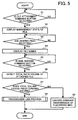
- Fig. 5 is a flow chart of the process procedure.
- the CPU 31 activates the electronic mail creation program and the transmission link program from the standard OS
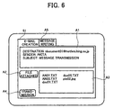
- an electronic mail creation screen 51 is displayed on the display 40 by the mail creation program as shown in Fig. 6.
- an electronic mail transmitting information display A1 a file attachment operation button A2, an attached file name display A3, an electronic mail sending command button A4, and the like are displayed.
- a tab A5 is selected to switch the screen to the screen shown in Fig. 7 and then the message can be input.
- the message is written in a message area A7.
- the electronic mail creation program can create an electronic mail and execute the function of the electronic mail sending unit to transmit the written electronic mail accompanied with a desired attached file.
- a file attachment operation button A2 shown in Fig. 6 is selected (step S1-Y).
- desired files stored in the HDD 17 or the storage unit 34 can be selected.
- a management state of files stored in the HDD 17 and the storage unit 34 is displayed on the screen as shown in (a) in Fig. 8 (it is shown on a directory 52) (step S2).
- the attached files can be selected from the files shown on the directory 52.
- the desired files step S3-Y
- the selected files are specified as attached files, and then the file names are displayed on the attached file name display A3 as shown in Fig. 6 (step S4).
- step S5-Y the mail sending command button A4 shown in Fig. 6 is selected (step S5-Y).
- the electronic mail creation program detects the total data volume of the attached files selected as described above (data volume detecting unit) (step S6).
- step S7-Y the process (transmission link process) shown in Fig. 9 is automatically initiated based on the transmission link program (step S8) (described later).
- step S8 the transmission link program
- step S9 an ordinary transmission of electronic mail with the written message that is sent by being accompanied with attached files is executed by the function of the electronic mail sending unit described above (step S9).
- a transfer end for the attached files selected at the step S3 is determined (step S11). That is, the attached files can be uploaded to a predetermined Internet server 61 through the transmission link program as shown in Fig. 10. In other words, it is allowed to use the File Transfer Protocol over the Internet 6.
- the attached files are to be concentratedly transferred (uploaded) to a specified folder 53 (folders 55 and 56. See Fig. 8.) in the Internet server 61 as shown in (b) in Fig. 8. Accordingly, the folder 53 capable of accepting the transfer is required in the Internet server 61 before initiation of the transfer. Preparation of the folder 53 in an authorized area in the Internet server 61 is allowed by the use of the File Transfer Protocol of the transmission link program.
- a name for the folder 53 is determined from the contents of a history information management table 54 (Fig. 11) managed by the transmission link program.
- the history information management table 54 managed by the transmission link program is a table to manage the folder 53 (folders 55 and 56) that has been prepared in the Internet server 61 in advance.
- history information management table 54 In the history information management table 54 are recorded a main folder 71 and a sub-holder 72 in which names of the main and sub-folders are cataloged, work history 73 to record whether data have been uploaded to the main folder 71 and sub-holder 72, transfer date 74 to show dates when the data uploads are executed, and transfer end user 75 to catalog electronic mail addresses of user destinations that are receiving ends to come to download the data from the main folder 71 and sub-folder 72 as described later.
- the main folder 71 and the sub-folder 73 that are not recorded with "Upload completed” on the work history 73 are selected from the history information management table 54 in Fig. 11 as usable names.
- "User 01" and "Store 05" as the names of the main folder 71 and the sub-folder 73, respectively, both of which are not recorded with "Upload completed” on the work history 73 are selected.
- the history information management table 54 shown in Fig. 11 is the data stored in the storage unit 34.
- a transfer end for the attached file is determined.
- the folder 53 allocated to the transfer end for the attached file is specified (step S11)
- preparation is made for allowing the attached file to be uploaded toward the folder 53 (step S12).
- the upload of the attached file to the Internet server 61 starts (step S 13).
- This upload is executed with the use of the File Transfer Protocol.
- the connection of the transmission link program to the Internet server 61 is temporarily terminated.
- "Upload completed" is recorded in the work history 73 corresponding to the appropriate main folder 71 and sub-folder 72 in the history information management table 54, and the date when the upload has been executed is recorded in the transfer date 74.
- the electronic mail address of the user destination of the electronic mail to be sent at a step S 17 described later is recorded in the column of the transfer end 75.
- the transmission link program prepares link information (step S 14).
- the link information means the information that allows a user that is a mail receiving end (user that is the file transfer end) to download the files (that were the attached files) uploaded to the Internet server 61 for file transfer.
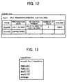
- the transmission link program is the display information and the like on the screen as shown in Figs. 12 and 13.
- the information is shown on a user's terminal 62 (Fig. 10) that is a file transfer end and is generally displayed with the use of Web browser software.
- it is a structured document that is generally called hypertext mark-up language (HTML) document.
- HTML hypertext mark-up language
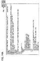
- the display shown in Fig. 12 displays the data shown in Fig. 14.
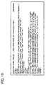
- the display shown in Fig. 13 displays the data shown in Fig. 15. Owing to the displays on the screen, a file transfer end user can know which files (the files attached to the electronic mail) should be obtained by downloading.
- the link information shown in Figs. 10 and 11 is prepared by the transmission link program (step S 14).
- the information and the condition settings to prepare the link information are prepared based on the contents in the history information management table 54 and the conditions set as default settings.
- the prepared link information is transferred to the Internet server 61 by the transmission link program, similarly to the uploading of the files described above (step S 15).
- the link information of "Index01.htm” is uploaded (numeral 57 in (c) in Fig. 8).
- the link information of "Index02.htm" is uploaded (numeral 58 in (c) in Fig. 8).
- the upload of the link information may be executed at the same time of the upload of the attached files or may be executed prior to the latter. This is because these orders are not necessary to be particularly limited to which is before or after.
- the processes of the steps from S11 to S15 as described above realize the file transmitting unit.
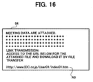
- the transmission link program executes editing to write the link information in the written message for the electronic mail as described above (step S16). For example, a uniform resource locator (URL) address A9 shown in Fig. 16 is written in the message area A7. In addition to this, the transmission link program deletes the attached files set to the electronic mail.
- a uniform resource locator (URL) address A9 shown in Fig. 16 is written in the message area A7.
- the transmission link program deletes the attached files set to the electronic mail.
- the user to whom the file was transferred can receive an electronic mail addressed to the user with the use of the electronic mail program of the Internet.
- the user can access to a mail server 63 of the provider with whom the user has a contract as shown in Fig. 10.
- the message of the electronic mail received is displayed on a screen 64 of the user terminal 62 that is the file transfer end as shown in Fig. 16.
- the Web browser software is set in the standard OS so as to be activated by the electronic mail program of the Internet.
- the user can demand the Internet server to download the files at the location shown by the URL.
- the notation, "ftp”, in the above is defined as executing the download of the file designated according to the File Transfer Protocol.
- the user terminal 62 is set so as to activate the file transfer program when this protocol is selected.
- step S5-Y when a user operates the digital color multifunction product 1 to send an electronic mail accompanied with desired attached files to the user destination (step S5-Y), the user sends the files that were intended to be sent with the electronic mail by attaching to the predetermined location, that is, the predetermined folder of the Internet server 61 in this example (step S 13), writes the information that allows downloading of the files, i.e., the URL showing the above location in this example, in the electronic mail, and sends the electronic mail without attaching the file (step S16).
- This allows the user to send files in a large volume to the user destination only by executing an operation of attaching desired files to the electronic mail without worrying about the data volume of the files attached to the electronic mail, resulting in an improvement of the usability of electronic mail.
- step S6 When the user intends to send an electronic mail accompanied with attached files, the data volume of the files designated to be attached to the electronic mail is detected in advance (step S6).
- step S7-Y When the data volume exceeds the predetermined volume (step S7-Y), it is judged improper for the electronic mail to be sent with the attached files as they are. Only in this case, the above processes are executed automatically. Therefore, when the data volume does not exceed the predetermined volume, the user destination can download the file from the electronic mail as usually done, which provides ease of use for the user destination.
- the file designated as the attached file is transmitted to the predetermined location on the network, information to allow downloading the attached file on the receiver side for the electronic mail is recorded in the electronic mail, which is sent to the user destination without being accompanied with the attached file.
- the user Even though the file is in a large volume, the user only carries out the operation to attach the file to the electronic mail, which allows the user destination to obtain the file. Thus, the user can attach the file in a large volume to the electronic mail in an easy operation.
Landscapes
- Engineering & Computer Science (AREA)
- Signal Processing (AREA)
- Multimedia (AREA)
- Computing Systems (AREA)
- General Engineering & Computer Science (AREA)
- Computer Networks & Wireless Communication (AREA)
- Information Transfer Between Computers (AREA)
- Computer And Data Communications (AREA)
- Facsimiles In General (AREA)
- Facsimile Transmission Control (AREA)
Abstract
Description
Claims (10)
- An electronic mail sending device comprising:a file designating unit that designates a file that is to be attached to an electronic mail;a file transmitting unit that transmits the file to a predetermined location that is connected to the electronic mail sending device via a network;a mail creating unit that creates an electronic mail that contains information that makes it possible for a receiver of the electronic mail to download the file from the location upon the file transmitting unit transmitting the file to the location; anda mail sending unit that sends the electronic mail created to the receiver via a network without attaching the file.
- The electronic mail sending device according to claim 1, further comprising a data volume detecting unit that detects data volume of the file designated by the file designating unit, wherein
the file transmitting unit transmits the file to the location upon the data volume detecting unit detecting that the data volume of the file exceeds a predetermined value. - The electronic mail sending device according to claim 1, wherein the information with which the mail creating unit creates the electronic mail is information about the location.
- The electronic mail sending device according to claim 3, wherein the information is a Uniform Resource Locator (URL) of the location.
- An information processor comprising:a file designating unit that designates a file that is to be attached to an electronic mail;a file transmitting unit that transmits the file to a predetermined location that is connected to the electronic mail sending device via a network;a mail creating unit that creates an electronic mail that contains information that makes it possible for a receiver of the electronic mail to download the file from the location upon the file transmitting unit transmitting the file to the location; anda mail sending unit that sends the electronic mail created to the receiver via a network without attaching the file.
- The information processor according to claim 5, further comprising a data volume detecting unit that detects data volume of the file designated by the file designating unit, wherein
the file transmitting unit transmits the file to the location upon the data volume detecting unit detecting that the data volume of the file exceeds a predetermined value. - An image processing system comprising:an information processor including
a file designating unit that designates a file that is to be attached to an electronic mail;
a file transmitting unit that transmits the file to a predetermined location that is connected to the electronic mail sending device via a network;
a mail creating unit that creates an electronic mail that contains information that makes it possible for a receiver of the electronic mail to download the file from the location upon the file transmitting unit transmitting the file to the location; and
a mail sending unit that sends the electronic mail created to the receiver via a network without attaching the file; andan image processor that executes predetermined image processing to the file, which is an image. - A computer program that contains instructions which when executed on a computer causes the computer to execute:designating a file that is to be attached to an electronic mail;transmitting the file to a predetermined location that is connected to the electronic mail sending device via a network;creating an electronic mail that contains information that makes it possible for a receiver of the electronic mail to download the file from the location, the creating is performed upon the file is transmitted in the transmitting; andsending the electronic mail created to the receiver via a network without attaching the file to the electronic mail.
- The computer program according to claim 8, further causing the computer realize detecting data volume of the file designated at the designating, wherein
the transmitting includes transmitting the file to the location upon it is detected at the detecting that the data volume of the file exceeds a predetermined value. - A computer-readable recording medium that stores a computer program that contains instructions which when executed on a computer causes the computer to execute:designating a file that is to be attached to an electronic mail;transmitting the file to a predetermined location that is connected to the electronic mail sending device via a network;creating an electronic mail that contains information that makes it possible for a receiver of the electronic mail to download the file from the location, the creating is performed upon the file is transmitted in the transmitting; andsending the electronic mail created to the receiver via a network without attaching the file to the electronic mail.
Applications Claiming Priority (2)
| Application Number | Priority Date | Filing Date | Title |
|---|---|---|---|
| JP2003306589A JP2005078278A (en) | 2003-08-29 | 2003-08-29 | E-mail transmission apparatus, information processing apparatus, image processing system, program, and storage medium |
| JP2003306589 | 2003-08-29 |
Publications (2)
| Publication Number | Publication Date |
|---|---|
| EP1511251A2 true EP1511251A2 (en) | 2005-03-02 |
| EP1511251A3 EP1511251A3 (en) | 2006-11-29 |
Family
ID=34101243
Family Applications (1)
| Application Number | Title | Priority Date | Filing Date |
|---|---|---|---|
| EP04255213A Ceased EP1511251A3 (en) | 2003-08-29 | 2004-08-27 | Device for sending electronic mail |
Country Status (3)
| Country | Link |
|---|---|
| US (1) | US7533151B2 (en) |
| EP (1) | EP1511251A3 (en) |
| JP (1) | JP2005078278A (en) |
Families Citing this family (55)
| Publication number | Priority date | Publication date | Assignee | Title |
|---|---|---|---|---|
| JP3818269B2 (en) * | 2003-03-28 | 2006-09-06 | ブラザー工業株式会社 | Information processing apparatus and program |
| US8120797B2 (en) | 2004-10-08 | 2012-02-21 | Sharp Laboratories Of America, Inc. | Methods and systems for transmitting content to an imaging device |
| US8006292B2 (en) | 2004-10-08 | 2011-08-23 | Sharp Laboratories Of America, Inc. | Methods and systems for imaging device credential submission and consolidation |
| US8001587B2 (en) | 2004-10-08 | 2011-08-16 | Sharp Laboratories Of America, Inc. | Methods and systems for imaging device credential management |
| US8001586B2 (en) | 2004-10-08 | 2011-08-16 | Sharp Laboratories Of America, Inc. | Methods and systems for imaging device credential management and authentication |
| US8115945B2 (en) | 2004-10-08 | 2012-02-14 | Sharp Laboratories Of America, Inc. | Methods and systems for imaging device job configuration management |
| US8060921B2 (en) | 2004-10-08 | 2011-11-15 | Sharp Laboratories Of America, Inc. | Methods and systems for imaging device credential authentication and communication |
| US8065384B2 (en) | 2004-10-08 | 2011-11-22 | Sharp Laboratories Of America, Inc. | Methods and systems for imaging device event notification subscription |
| US8018610B2 (en) | 2004-10-08 | 2011-09-13 | Sharp Laboratories Of America, Inc. | Methods and systems for imaging device remote application interaction |
| US8015234B2 (en) | 2004-10-08 | 2011-09-06 | Sharp Laboratories Of America, Inc. | Methods and systems for administering imaging device notification access control |
| US8115947B2 (en) | 2004-10-08 | 2012-02-14 | Sharp Laboratories Of America, Inc. | Methods and systems for providing remote, descriptor-related data to an imaging device |
| US8006176B2 (en) | 2004-10-08 | 2011-08-23 | Sharp Laboratories Of America, Inc. | Methods and systems for imaging-device-based form field management |
| US7978618B2 (en) | 2004-10-08 | 2011-07-12 | Sharp Laboratories Of America, Inc. | Methods and systems for user interface customization |
| US8024792B2 (en) | 2004-10-08 | 2011-09-20 | Sharp Laboratories Of America, Inc. | Methods and systems for imaging device credential submission |
| US8156424B2 (en) | 2004-10-08 | 2012-04-10 | Sharp Laboratories Of America, Inc. | Methods and systems for imaging device dynamic document creation and organization |
| US8051125B2 (en) | 2004-10-08 | 2011-11-01 | Sharp Laboratories Of America, Inc. | Methods and systems for obtaining imaging device event notification subscription |
| US8125666B2 (en) | 2004-10-08 | 2012-02-28 | Sharp Laboratories Of America, Inc. | Methods and systems for imaging device document management |
| US8051140B2 (en) | 2004-10-08 | 2011-11-01 | Sharp Laboratories Of America, Inc. | Methods and systems for imaging device control |
| US8237946B2 (en) | 2004-10-08 | 2012-08-07 | Sharp Laboratories Of America, Inc. | Methods and systems for imaging device accounting server redundancy |
| US8171404B2 (en) | 2004-10-08 | 2012-05-01 | Sharp Laboratories Of America, Inc. | Methods and systems for disassembly and reassembly of examination documents |
| US8115944B2 (en) | 2004-10-08 | 2012-02-14 | Sharp Laboratories Of America, Inc. | Methods and systems for local configuration-based imaging device accounting |
| US8049677B2 (en) | 2004-10-08 | 2011-11-01 | Sharp Laboratories Of America, Inc. | Methods and systems for imaging device display element localization |
| US7873553B2 (en) | 2004-10-08 | 2011-01-18 | Sharp Laboratories Of America, Inc. | Methods and systems for authorizing imaging device concurrent account use |
| US8006293B2 (en) | 2004-10-08 | 2011-08-23 | Sharp Laboratories Of America, Inc. | Methods and systems for imaging device credential acceptance |
| US7969596B2 (en) | 2004-10-08 | 2011-06-28 | Sharp Laboratories Of America, Inc. | Methods and systems for imaging device document translation |
| US7920101B2 (en) | 2004-10-08 | 2011-04-05 | Sharp Laboratories Of America, Inc. | Methods and systems for imaging device display standardization |
| US8115946B2 (en) | 2004-10-08 | 2012-02-14 | Sharp Laboratories Of America, Inc. | Methods and sytems for imaging device job definition |
| US8060930B2 (en) | 2004-10-08 | 2011-11-15 | Sharp Laboratories Of America, Inc. | Methods and systems for imaging device credential receipt and authentication |
| US8384925B2 (en) | 2004-10-08 | 2013-02-26 | Sharp Laboratories Of America, Inc. | Methods and systems for imaging device accounting data management |
| US8032579B2 (en) | 2004-10-08 | 2011-10-04 | Sharp Laboratories Of America, Inc. | Methods and systems for obtaining imaging device notification access control |
| US8032608B2 (en) | 2004-10-08 | 2011-10-04 | Sharp Laboratories Of America, Inc. | Methods and systems for imaging device notification access control |
| US7870185B2 (en) | 2004-10-08 | 2011-01-11 | Sharp Laboratories Of America, Inc. | Methods and systems for imaging device event notification administration |
| US8001183B2 (en) | 2004-10-08 | 2011-08-16 | Sharp Laboratories Of America, Inc. | Methods and systems for imaging device related event notification |
| US8120799B2 (en) | 2004-10-08 | 2012-02-21 | Sharp Laboratories Of America, Inc. | Methods and systems for accessing remote, descriptor-related data at an imaging device |
| US8023130B2 (en) | 2004-10-08 | 2011-09-20 | Sharp Laboratories Of America, Inc. | Methods and systems for imaging device accounting data maintenance |
| US7934217B2 (en) | 2004-10-08 | 2011-04-26 | Sharp Laboratories Of America, Inc. | Methods and systems for providing remote file structure access to an imaging device |
| US7970813B2 (en) | 2004-10-08 | 2011-06-28 | Sharp Laboratories Of America, Inc. | Methods and systems for imaging device event notification administration and subscription |
| US8035831B2 (en) | 2004-10-08 | 2011-10-11 | Sharp Laboratories Of America, Inc. | Methods and systems for imaging device remote form management |
| US8213034B2 (en) | 2004-10-08 | 2012-07-03 | Sharp Laboratories Of America, Inc. | Methods and systems for providing remote file structure access on an imaging device |
| US8120793B2 (en) | 2004-10-08 | 2012-02-21 | Sharp Laboratories Of America, Inc. | Methods and systems for displaying content on an imaging device |
| US8230328B2 (en) | 2004-10-08 | 2012-07-24 | Sharp Laboratories Of America, Inc. | Methods and systems for distributing localized display elements to an imaging device |
| US7873718B2 (en) | 2004-10-08 | 2011-01-18 | Sharp Laboratories Of America, Inc. | Methods and systems for imaging device accounting server recovery |
| US20060085749A1 (en) * | 2004-10-15 | 2006-04-20 | Daniel Stuart W | System and method for using customizable phrasebooks on multi-function devices |
| JP4789100B2 (en) * | 2004-10-19 | 2011-10-05 | 伸 吉村 | E-mail transmission system |
| US8428484B2 (en) | 2005-03-04 | 2013-04-23 | Sharp Laboratories Of America, Inc. | Methods and systems for peripheral accounting |
| JP2007043703A (en) * | 2005-07-29 | 2007-02-15 | Sharp Corp | File structure data access method, file structure data providing system, image processing apparatus, and file structure conversion apparatus |
| JP4605021B2 (en) * | 2006-01-06 | 2011-01-05 | 村田機械株式会社 | Document management device |
| US7882185B2 (en) * | 2006-09-26 | 2011-02-01 | International Business Machines Corporation | Method and apparatus for managing e-mail attachments |
| US8345272B2 (en) | 2006-09-28 | 2013-01-01 | Sharp Laboratories Of America, Inc. | Methods and systems for third-party control of remote imaging jobs |
| JP5530767B2 (en) * | 2010-03-17 | 2014-06-25 | 株式会社野村総合研究所 | Authentication management device |
| JP5483564B2 (en) * | 2010-03-17 | 2014-05-07 | 株式会社野村総合研究所 | Authentication management device |
| JP5483563B2 (en) * | 2010-03-17 | 2014-05-07 | 株式会社野村総合研究所 | Authentication management device |
| JP2013145608A (en) * | 2013-05-01 | 2013-07-25 | Nomura Research Institute Ltd | Transmission control system and method for electronic mail |
| US9319563B1 (en) * | 2015-02-05 | 2016-04-19 | Kabushiki Kaisha Toshiba | Image processing device and method for processing image data |
| KR101774422B1 (en) * | 2015-08-17 | 2017-09-05 | 네이버 주식회사 | Method and system for transmitting text messages |
Family Cites Families (11)
| Publication number | Priority date | Publication date | Assignee | Title |
|---|---|---|---|---|
| US5781901A (en) * | 1995-12-21 | 1998-07-14 | Intel Corporation | Transmitting electronic mail attachment over a network using a e-mail page |
| JPH11136281A (en) | 1997-10-31 | 1999-05-21 | Hitachi Ltd | E-mail system, e-mail processing method, and mail server device |
| US20020016818A1 (en) * | 2000-05-11 | 2002-02-07 | Shekhar Kirani | System and methodology for optimizing delivery of email attachments for disparate devices |
| JP4419282B2 (en) * | 2000-06-14 | 2010-02-24 | ソニー株式会社 | Information processing apparatus, information processing method, information management system, and program storage medium |
| JP2002259307A (en) * | 2001-03-02 | 2002-09-13 | Fujitsu Ltd | Information processing apparatus, information transmission method, computer-readable recording medium, and program therefor |
| JP2002278900A (en) | 2001-03-16 | 2002-09-27 | Murata Mach Ltd | File communication equipment |
| JP2002297522A (en) * | 2001-03-30 | 2002-10-11 | Minolta Co Ltd | Data transmitter, data transmission method, program, and recording medium |
| JP3857104B2 (en) | 2001-10-23 | 2006-12-13 | 株式会社リコー | Image communication device |
| US20040036720A1 (en) * | 2002-08-22 | 2004-02-26 | Eastman Kodak Company | Simplified method of printing a digital image |
| US9503280B2 (en) * | 2003-03-17 | 2016-11-22 | Accellion Pte Ltd. | Methods and systems for email integrated file delivery |
| US20040215696A1 (en) * | 2003-03-31 | 2004-10-28 | Clay Fisher | Method and apparatus for generating a message with embedded content |
-
2003
- 2003-08-29 JP JP2003306589A patent/JP2005078278A/en active Pending
-
2004
- 2004-08-27 EP EP04255213A patent/EP1511251A3/en not_active Ceased
- 2004-08-27 US US10/927,104 patent/US7533151B2/en active Active
Also Published As
| Publication number | Publication date |
|---|---|
| JP2005078278A (en) | 2005-03-24 |
| US7533151B2 (en) | 2009-05-12 |
| EP1511251A3 (en) | 2006-11-29 |
| US20050050149A1 (en) | 2005-03-03 |
Similar Documents
| Publication | Publication Date | Title |
|---|---|---|
| US7533151B2 (en) | Electronic mail sending device, information processor, image processing system, and computer product | |
| US7573615B2 (en) | Multi-function image forming apparatus with improved scan-to-email function | |
| US8885201B2 (en) | Image forming apparatus and scanned data process method | |
| US7978353B2 (en) | Document input and output device having security protection function and document input and output method of the device | |
| US7796293B2 (en) | Image processing apparatus, and computer product, allowing selective resolution of an area of a document | |
| US20110199641A1 (en) | Received document input and output device and input and output method of received document | |
| US7505167B2 (en) | Information processing apparatus, method, and computer product, for file naming | |
| US20070050460A1 (en) | Document input and output device for identifying external devices and identifying processing method of document input and output device | |
| US20050066274A1 (en) | Image processing apparatus, information processing apparatus, and computer product | |
| US7769249B2 (en) | Document OCR implementing device and document OCR implementing method | |
| JP5004746B2 (en) | Data communication apparatus, control method and program for data communication apparatus | |
| JP4536623B2 (en) | External device document input / output device | |
| JP3665873B2 (en) | Network broadcast transmission apparatus, network broadcast reply method, network broadcast transmission program, and recording medium | |
| JP3565167B2 (en) | Internet facsimile machine | |
| JP2006085255A (en) | Image processing apparatus, image processing system, setting processing method, storage medium storing computer-readable program, and program | |
| JP3941750B2 (en) | Communication device | |
| JP4461852B2 (en) | Information processing device | |
| KR101116608B1 (en) | Method and apparatus for uploading scan data | |
| JP2005006079A (en) | Information processing apparatus, program, and storage medium | |
| JP2008098979A (en) | Multifunction device and image transfer method | |
| WO2019044655A1 (en) | Image-reading device and image-reading method | |
| JP2006309411A (en) | File converter | |
| JP2003163782A (en) | Communication terminal | |
| JP2006229325A (en) | Image communications apparatus | |
| JP2005004625A (en) | Data processing method, image processing apparatus, program, and storage medium |
Legal Events
| Date | Code | Title | Description |
|---|---|---|---|
| PUAI | Public reference made under article 153(3) epc to a published international application that has entered the european phase |
Free format text: ORIGINAL CODE: 0009012 |
|
| 17P | Request for examination filed |
Effective date: 20040915 |
|
| AK | Designated contracting states |
Kind code of ref document: A2 Designated state(s): AT BE BG CH CY CZ DE DK EE ES FI FR GB GR HU IE IT LI LU MC NL PL PT RO SE SI SK TR |
|
| AX | Request for extension of the european patent |
Extension state: AL HR LT LV MK |
|
| PUAL | Search report despatched |
Free format text: ORIGINAL CODE: 0009013 |
|
| AK | Designated contracting states |
Kind code of ref document: A3 Designated state(s): AT BE BG CH CY CZ DE DK EE ES FI FR GB GR HU IE IT LI LU MC NL PL PT RO SE SI SK TR |
|
| AX | Request for extension of the european patent |
Extension state: AL HR LT LV MK |
|
| 17Q | First examination report despatched |
Effective date: 20070122 |
|
| AKX | Designation fees paid |
Designated state(s): DE ES FR GB IT NL |
|
| STAA | Information on the status of an ep patent application or granted ep patent |
Free format text: STATUS: THE APPLICATION HAS BEEN REFUSED |
|
| 18R | Application refused |
Effective date: 20090203 |