BACKGROUND OF THE INVENTION
The present invention relates to a moving device, image
reading device and image forming apparatus, and especially,
to a moving device by which a generation of speed unevenness
of the movement is suppressed and a moving object is smoothly
moved, an image reading device and an image forming
apparatus.
DESCRIPTION OF RELATED ART
Generally, in various fields, a moving device for
linearly moving a moving object is used, by using a DC motor,
stepping motor or linear motor, as a driving source. As a
device to which such a moving device is applied, for example,
there is an image reading device by which, while linearly
moving a recording medium in which an image is recorded, as a
moving object, by a moving device, an image is read by
scanning a laser light in the direction perpendicular to the
moving direction, or an image forming apparatus in which,
while reciprocally moving a laser irradiation device which is
a moving object by a moving device, by irradiating the laser
light to a recording medium conveyed in the direction
perpendicular to the moving direction of the laser light
irradiation device, according to a predetermined image data,
and an image is formed.
Particularly, in a field of the medical care, a
radiation image is widely used for a disease diagnosis, and
as a method for obtaining this radiation image, a method is
conducted by which, after the radiation transmitted through
the subject is accumulated and recorded in a stimulative
fluorescent substance sheet, and when an excitation light is
irradiated by the image reading device, the accumulated and
recorded radiation energy is stimulation light-emitted, and
when the intensity of this stimulatively emitted light is
converted into an electric signal, and according to this
electric signal, a visual image is formed in the recording
medium by the image forming apparatus.
In the image reading device and image forming
apparatus, used in the field of the medical care as described
above, especially, from a viewpoint in which the diagnosis of
disease is conducted according to the obtained image, it is
required that a very fine image is obtained. In order to
obtain the very fine image, because it is necessary that the
scanning of the recording medium or the laser light
irradiation device is accurately and smoothly conducted,
recently, it is proposed that a linear motor is used as a
drive source of the moving device for linearly moving the
recording medium or the laser light irradiation device.
As the image forming apparatus in which the linear
motor is used as the drive source for the movement of the
laser light irradiation device, the image forming apparatus
which has a cylindrical support drum rotatable while
supporting the recording medium, and the laser light
irradiation device which is provided in opposite to this
support drum, and while reciprocally moving in the width
direction of the recording medium, according to a
predetermined image data, irradiates the laser light, and in
which the linear motor to move this laser light irradiation
device is provided, is well-known (for example, refer to
Patent Document 1).
This image forming apparatus has a holding section
which holds the laser light irradiation device which is the
moving object, and on almost central portion of the lower
surface of this holding section, a movable coil whose
sectional shape is L letter-shape constituting a linear
motor, is provided, and is arranged in a situation that the
movable coil is sandwiched in a magnet section whose section
is C letter-shape provided on the lower portion of the
holding section, and on the lower portion of both ends of the
holding section, the moving device in which guided members by
which the movement of the holding member is guided, are
respectively provided, is applied.
[Patent Document 1] Tokkai-hei 11-216921.
However, in the conventional technology, because the
object to be conveyed is conveyed in such a manner that it is
arranged so as to be sandwiched in parallel to a linear motor
by two guide members, by the sliding-movement resistance of
two guides, the delay is generated in a single of them, or
depending on the parallel balance at the time of assembling,
the vibration is generated and the smooth conveyance can not
be conducted, and thereby, the speed unevenness of the object
to be conveyed is worsened, and when the stimulative
fluorescent plate is scanned by the stimulative excitation
light, the image unevenness is generated, and there is a case
where the diagnostic image is hindered. Further, because a
plurality of guide members are used, there is a problem that
the apparatus becomes large and the cost is increased.
Further, in such a conventional technology, when the
rigidity of a horizontal portion and vertical portion of the
movable coil are insufficient, a delay is generated in the
holding section to the conveying speed of the linear motor,
or the vibration is generated and the smooth conveyance can
not be conducted, and as a result, the position dislocation
is generated in the irradiation of the laser light to the
recording medium by the laser light irradiation device held
by the holding section, and there is a case where the image
unevenness is generated. Accordingly, in order to obtain a
fine image, it is necessary that the rigidity of the movable
coil is increased, as a result, there is a problem that it is
necessary that the movable coil has a dimension more than a
predetermined one, and there is a limitation in the size
reduction and the cost reduction of the apparatus.
Further, in the linear motor whose magnet section is c-letter
shape, the using efficiency of the magnetic flux is
not good, and when the large thrust is wanted to obtain, it
is necessary that the magnetic flux density is increased, and
as a result, also because the dimension of the magnet section
is increased, there is a limitation in the size reduction and
the cost reduction of the apparatus.
In view of such a problem of the conventional
technology, the first object of the present invention is to
provide an image reading device in which the cost is low and
the size is reduced, and by which a fine diagnostic image
having no image unevenness is obtained.
Further, in the conventional technology, an encoder to
detect a position of the moving object or the moving speed is
provided in the vicinity of the moving device, and according
to the detection result by this encoder, the drive of the
moving device is appropriately controlled, however, when a
linear scale constituting the encoder is not provided in
parallel to the moving direction of the laser light
irradiation device, or when the linear scale and a sensor
section for reading the linear scale are not provided in
parallel to each other, because a position of the laser light
irradiation device or the moving speed is not exactly
detected, it is not correctly controlled as in the case where
the speed unevenness is generated in the conveyance by the
linear motor of the laser light irradiation device.
Accordingly, also in this point, the position dislocation is
generated in the irradiation of the laser light to the
recording medium, and there is a case where the image
unevenness is generated.
Accordingly, the second object of the present invention
is to provide a moving device which can smoothly move the
moving object while the generation of the speed unevenness of
the movement is prevented, by a small size and low cost
device structure, and an image reading device and an image
forming apparatus by which a very fine image can be obtained
by applying this moving device.
SUMMARY OF THE INVENTION
Above-described problems are solved by one of the
following items.
According to the invention written in item 22, by the
moving device in which the speed unevenness at the time of
moving operation is decreased, because the recording medium
or the recording section, which is the moving object, is
conveyed, the scanning of the recording medium or the
recording section is smoothly conducted.
Following is the effects of each embodiments stated
above.
According to the invention written in item 1, when the
movable coil is fixed in the apparatus, it becomes a shape by
which the rigidity is easily obtained, and because, without
making the movable coil larger than it needs, it is prevented
that the delay of the moving speed is generated to the
conveying speed of the linear motor, the vibration is not
generated, and the recording medium or the reading section is
smoothly conveyed, thereby, the very fine image can be
obtained by a small-sized and low cost apparatus structure.
Further, when the peripheral surface of shaft-like
magnet section is covered by the movable coil, the using
efficiency of the magnetic flux is good, and even when it is
wanted that the large thrust is obtained, because it comes
off without making the dimension of the magnet section larger
than it needs, the size reduction and cost reduction of the
apparatus can be intended.
According to the invention written in item 2, because
the guide section for guiding the moving object is provided,
and because the recording medium or reading section, which is
the moving object, is more smoothly conveyed, further very
fine image can be obtained.
According to the invention written in item 3, because
the guide section is singular, more size reduction and cost
reduction of the whole apparatus can be intended.
According to the invention written in item 4, even when
the moving direction is a vertical direction, without making
the movable coil larger than it needs, it is prevented that
the delay of the moving speed is generated to the conveying
speed of the linear motor, and because, without the
generation of the vibration, the recording medium or reading
section is smoothly conveyed, a very fine image can be
obtained by the small size and low cost apparatus structure.
Further, when the peripheral surface of the shaft-like
magnet section is covered by the movable coil, the using
efficiency of the magnetic flux is good, and even when it is
wanted that the large thrust is obtained, because it comes
off without making the dimension of the magnet section larger
than it needs, the size reduction and cost reduction of the
apparatus can be intended.
According to the invention written in item 5, when the
moving body is risen by the linear motor, because the
balancing weight is dropped by the self-weight, and the
thrust by the linear motor can be decreased, the magnet
section and the movable coil can be more size-reduced,
thereby, the size reduction and the cost reduction of the
apparatus can be intended.
According to the invention written in item 6, when the
drive of the linear motor is stopped, it can be prevented
that the moving body or the balancing weight is dropped by
the self-weight.
According to the invention written in item 7, when the
movable coil is fixed in the apparatus, it becomes a shape by
which the rigidity can be easily obtained, and without making
the dimension of the movable coil larger than it needs, it is
prevented that the delay of the moving speed is generated to
the conveying speed of the linear motor, and because, without
the generation of the vibration, the recording medium or the
recording section is smoothly conveyed, a very fine image can
be obtained by the small sized and low cost apparatus
structure.
Further, when the peripheral surface of the shaft-like
magnet section is covered by the movable coil, the using
efficiency of the magnetic flux is good, and even when it is
wanted that the large thrust is obtained, because it comes
off without making the dimension of the magnet section larger
than it needs, the size reduction and cost reduction of the
apparatus can be intended.
According to the invention written in item 8, because
the guide section for guiding the moving object is provided,
and the recording medium or reading section, which is the
moving object, is more smoothly conveyed, further very fine
image can be obtained.
According to the invention written in item 9, because
the guide section is singular, more size reduction and cost
reduction of the whole apparatus can be intended. Also, it
becomes possible to suppress speed unevenness generated by
the delay of conveyance speed and the vibration caused by the
differences of the mechanical sliding resistances of two
guide members by introducing one guide member structure.
According to the invention written in item 10, even
when the moving direction is a vertical direction, without
making the movable coil larger than it needs, it is prevented
that the delay of the moving speed is generated to the
conveying speed of the linear motor, and because, without the
generation of the vibration, the recording medium or reading
section is smoothly conveyed, a very fine image can be
obtained by the small size and low cost apparatus structure.
Further, when the peripheral surface of the shaft-like
magnet section is covered by the movable coil, the using
efficiency of the magnetic flux is good, and even when it is
wanted that the large thrust is obtained, because it comes
off without making the dimension of the magnet section larger
than it needs, the size reduction and cost reduction of the
apparatus can be intended.
According to the invention written in item 11, when the
moving body is risen by the linear motor, because the
balancing weight is dropped by the self-weight, and the
thrust by the linear motor can be decreased, a size of the
magnet section and movable coil can be more reduced, and
therefore, the size reduction and cost reduction of the
apparatus can be intended.
According to the invention written in item 12, when the
drive of the linear motor is stopped, it can be prevented
that the moving body or the balancing weight is dropped by
the self-weight.
According to the invention written in item 13, because
the movable coil becomes a shape by which the rigidity is
easily obtained, by the small sized and low cost apparatus
structure, it is prevented that the delay of the moving speed
is generated to the conveying speed of the linear motor, and
the vibration is decreased, and the moving object can be
smoothly conveyed.
Further, because the linear motor and the guide member
are arranged in a row along the direction perpendicular to
the moving direction of the moving object, and the balance in
the direction perpendicular to the moving direction is good,
further, each of components is proximately provided, the
influence of the assembling accuracy of each component is
hardly affected, and because the speed unevenness when the
moving operation is conducted, is decreased, the moving
object can be smoothly moved.
According to the invention written in item 14, because
the linear motor, the guide member and the encoder are
arranged in a row along the direction perpendicular to the
moving direction of the moving object, and the balance in the
direction perpendicular to the moving direction is good,
further, because each of components is proximately provided,
the influence of the assembling accuracy of each component is
hardly affected, and because the speed unevenness when the
moving operation is conducted, is decreased, the moving
object can be smoothly moved.
Further, because the sensor section is directly
provided to the movable coil for moving the moving object,
and a position or the moving speed of the moving object is
accurately detected, the speed unevenness of the moving
object is suppressed and correctly controlled, and at this
result, the moving object can be smoothly moved.
According to the invention written in item 15, because
the holding section is hardly affected by the magnetic field
formed of the magnet section, even when the magnetic
substance is used in the holding section, when the moving
operation is conducted, because there is no case where it is
attracted to the magnet section, the speed unevenness of the
movement is suppressed, and as this result, the moving object
can be smoothly moved.
According to the invention written in item 16, because
the guided member is hardly affected by the magnetic field
formed of the magnet section, even when the magnetic
substance is used in the guided member, when the moving
operation is conducted, because there is no case where it is
attracted to the magnet section, the speed unevenness of the
movement is suppressed, and as this result, the moving object
can be smoothly moved.
According to the invention written in item 17, even
when the moving operation is conducted in the vertical
direction, the speed unevenness is decreased, and the moving
object can be smoothly moved.
According to the invention written in item 18, when the
moving object is risen by the linear motor, because the
balancing weight is dropped by the self-weight, the thrust by
the linear motor can be decreased.
According to the invention written in item 19, because
the linear scale is parallel to the moving direction of the
moving object, by the positioning member, and is fitted to
the fitting surface so that it is parallel in the width
direction to the sensor section, and a position or the moving
speed of the moving object is correctly detected, the speed
unevenness is suppressed, and the moving object can be
smoothly moved.
According to the invention written in item 20, because
the sensor section is fitted to the fitting surface so that
the opposite surface to the linear scale of the sensor
section is parallel to the linear scale, and a position or
the moving speed of the moving object is correctly detected,
the speed unevenness is suppressed and the moving object can
be smoothly moved.
According to the invention written in item 21, because,
by the moving device in which the speed unevenness is
decreased at the time of moving operation, the recording
medium or reading section, which is the moving object, is
conveyed, the scanning of the recording medium or reading
section is smoothly conducted, as this result, a very fine
image can be obtained.
According to the invention written in item 22, because,
by the moving device in which the speed unevenness is
decreased at the time of moving operation, the recording
medium or reading and recording section, which is the moving
object, is conveyed, the scanning of the recording medium or
recording section is smoothly conducted, and as this result,
a very fine image can be obtained.
BRIEF DESCRIPTION OF THE DRAWINGS
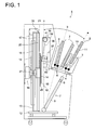
Fig. 1 is a view showing the structure of an embodiment
of an image reading device according to the present
invention.
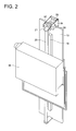
Fig. 2 is a perspective view showing a conveying
mechanism of a linear motor part.
Fig. 3 is a plan view showing a conveying mechanism of
a linear motor part.
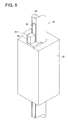
Fig. 4 is a perspective view showing the structure of
an encoder in the third embodiment.
Fig. 5 is a plan view showing the structure of an
encoder in the third embodiment.
Fig. 6 is a view showing the structure of an embodiment
of an image forming apparatus according to the present
invention.
Fig. 7 is a perspective view showing a fitting method
of a linear scale in the fourth embodiment.
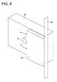
Fig. 8 is a perspective view showing a fitting method
of a sensor section in the fourth embodiment.
DETAILED DESCRIPTION OF THE INVENTION
Referring from Fig. 1 to Fig. 3, the first embodiment
of the invention will be described below, and referring to
Fig. 4 and Fig. 5, the third embodiment will be described,
and their operations will be individually described later.
Fig. 1 is a view in which an embodiment of an image
reading device 1 according to the present invention is shown,
and on an upper portion of the front side of this image
reading device 1, an insertion inlet 3 into which a cassette
2 in which a stimulative fluorescent substance sheet 14 as a
recording medium in which an image is recorded is housed, is
inserted, is provided, and on a lower end portion of this
insertion inlet 3, a feeding roller 4 for feeding the
cassette 2 into the inside of the image reading device 1 is
provided.
On an upper portion of the front side of the image
reading device 1, and furthermore, on a rear portion of the
insertion inlet 3, a take-out opening 5 for taking out the
reading processed cassette 2 is provided, and on the lower
end portion of this take-out opening 5, a sending roller 6
for sending the cassette 2 to the outside of the image
reading device 1, is provided.
On the lower portion of the front side of the image
reading device 1, a cassette conveying device 7 for conveying
the cassette 2 to a predetermined position is rotatably
provided by making the lower end a support shaft, by a drive
mechanism, not shown, and it can be stopped at each position
of a position a corresponding to the insertion inlet 3, a
position b corresponding to the take-out opening 5, and a
position c at which the cassette 2 is almost vertical.
The cassette conveying device 7 has a box-like cassette
supporting section 8 in which the upper surface and the rear
surface are opened, and in the cassette supporting section 8,
an elevation table 9 by which the lower end portion of the
cassette 2 is supported and which can be risen and fallen is
provided.
Further, in the cassette supporting section 8, a lock
releasing mechanism (not shown) by which the cassette 2 can
be separated into a back plate 10 by which the stimulative
fluorescent substance sheet 14 is held from the rear surface,
and a front plate 11 by which the surface of the stimulative
fluorescent substance sheet 14 is covered, is provided. As
the lock releasing mechanism, for example, a lock releasing
mechanism disclosed in Tokkai 2002-278000, can be used.
On the rear surface side of the image reading device 1,
a plate-like supporting member 13 extending from a base table
12 to the vertical direction, is provided, and by the
supporting member 13, a moving body 15 which holds the
stimulative fluorescent substance sheet 14 and can move in
the vertical direction, and a balancing weight 16 balancing
with this moving body 15, are supported relatively in a
manner which can go up and down through a connecting member
17.
At the center of front surface of the supporting member
13, as shown in from Fig. 1 to Fig. 3, the first guide rail
18 as a guide member for guiding the moving body 15 in the
vertical direction, is provided, and at the center of rear
surface, the second guide rail 19 for guiding the balancing
weight 16 in the vertical direction, is provided.
At a position opposite to the first guide rail 18, a
magnet section 20 constituting the linear motor is supported
by a supporting piece 21 integrally formed with the
supporting member 13 and provided in a extending manner in
the vertical direction. The magnet section 20 has, As shown
in Fig. 4, a permanent magnet 22 whose section is
cylindrical, in which mutual N poles or S poles are connected
and which is formed into shaft-like, and on the peripheral
surface of this permanent magnet 22, a covering member 23
formed of nonmagnetic material covering the permanent magnet
22, is provided.
On the peripheral surface of this covering member 23,
as shown in Fig. 4 and Fig. 5, a flat portion 24 which is
flat in a predetermined length in the peripheral direction,
is formed extending in the axis direction, and on this flat
portion 24, a linear scale 25 constituting the encoder for
detecting a position or the moving speed of the moving body
15 is provided in an extending manner in the axial direction
of the magnet section 20.
The moving body 15 has, as shown in from Fig. 1 to Fig.
3, a plate-like holding section 26 holding a back plate 10 of
the cassette 2 which supports the stimulative fluorescent
substance sheet 14. On the surface of this holding section
26, a rubber-magnet is provided, and the back plate 10 of the
cassette 2 is structured in such a manner that, to the main
body formed of synthetic resins, a ferromagnetic substance
sheet is adhered, and thereby, the back plate 10 is adhered
to the holding section 26 by the magnetic force, and held.
At a position which is the rear surface center of the
holding section 26, and corresponding to the magnet section
20, a movable coil 27 constituting the linear motor is
provided, and this movable coil 27 has a coil which is
cylindrically formed, and this coil is covered by a box-shaped
cover member. Then, the linear motor is structured in
such a manner that the magnet section 20 penetrates the
center of the movable coil 27.
At a position which is the upper surface of the movable
coil 27, and opposite to the linear scale 25, as shown in
Fig. 4 and Fig. 5, a sensor section 28 for constituting the
encoder and for reading the linear scale 25, is provided by
being supported by the supporting section 29 integrally
molded with the movable coil 27.
On the surface of the movable coil 27 opposite to a
fitting surface of the holding section, as shown in Fig. 1,
the first guided member 30 whose section is C-shaped, guided
by the first guide rail 18, is integrally provided with the
movable coil 27. The first guided member 30 and the magnet
section 20 are arranged at a distance more than a pitch
length of the permanent magnet 22.
Further, the balancing weight 16 has the second guided
member 31 whose section is C-shaped, guided by the second
guide rail 19.
Hereupon, the moving body 15 represents a movable
member to the magnet section 20, and in the present
embodiment, it is structured by the movable coil 27, holding
section 26, first guided member 30 and sensor section 28.
On the front side upper the supporting member 13, the
first pulley 32 is provided, and on the rear side, the second
pulley 33 and the third pulley 34 are provided upper and
lower it. Across these pulleys 32, 33, 34, belt-like
connecting member 17 is put. Hereupon, as the connecting
member 17, a steal wire can also be used.
Further, on the shaft portion of the first pulley 32, a
torque limiter for stopping the rotation operation of the
first pulley 32, one-way clutch, a brake mechanism 35 such as
an electromagnetic brake, are provided.
At a position which is an upper portion of the movable
range of the moving body and opposite to the moving body 15,
a reading section 36 for reading the radiation energy which
is accumulated and recorded in the stimulative fluorescent
substance sheet 14 held by the moving body 15, is provided.
The reading section 36 has: a laser light irradiation
device 37 by which a laser light L1 is irradiated on the
stimulative fluorescent substance sheet 14 while making the
laser light scan in the direction perpendicular to the moving
direction of the moving body 15; a light guiding plate 38 by
which the stimulative emitting light L2 excited when the
laser light L1 is irradiated on the stimulative fluorescent
substance sheet 14 by the laser light irradiation device 37,
is guided; a light collecting tube 39 for light-collecting
the stimulative emitting light L2 guided by the light guiding
plate 38; and a photoelectric converter 41 by which the
stimulative emitting light L2 light-collected by the light
collecting tube 39 is converted into an electric signal.
Below the reading section 36, an erasing device 40 for
irradiating an erasing light on the stimulative fluorescent
substance sheet 14 for discharging the radiation energy
remained on the stimulative fluorescent substance sheet 14,
after the radiation energy is reading-processed by the
reading section 36, is provided.
Next, operations of the first embodiment will be
described.
When the reading processing of the image is conducted,
the cassette conveying device 7 is made to stand ready for at
a psosition a corresponding to the insertion inlet 3, and in
this situation, when the cassette 2 in which the cassette 2
in which the stimulative fluorescent substance sheet 14 in
which the radiation image is recorded is housed, is inserted
from the insertion inlet 3, the cassette 2 is sent into the
cassette conveying device 7 by the feeding roller 4. Then,
the elevation table 9 is lowered under a condition that the
lower end portion of the cassette 2 is supported, the
cassette 2 is housed in the cassette conveying device 7, and
when the lock release mechanism is operated, the cassette 2
is in a condition that it can be separated into the front
plate 11 and the back plate 10 by which the stimulative
fluorescent substance sheet 14 is held.
After that, the cassette conveying device 7 is moved to
a position c at which the cassette 2 is almost vertical. At
this time, when the moving body is positioned at the
undermost end of movable range, it becomes a condition that
the holding section 26 and the back plate 10 of the cassette
2 are opposed to each other, and by the magnetic force, the
back plate 10 by which the stimulative fluorescent substance
sheet 14 is supported, is attracted to the holding section
26, and is separated from the front plate 11 and under the
condition that the surface of the stimulative fluorescent
substance sheet 14 is exposed, it is held by the holding
section 26. Hereupon, the cassette conveying device 7 may be
retreated at a position b corresponding to the taking out
opening 5 under the condition that the front plate 11 is held
by it.
After that, the linear motor is driven, and the moving
body 15 is risen along the first guide rail 18. Thereby, the
stimulative fluorescent substance sheet 14 is conveyed to a
position opposite to the reading section 36, the laser light
L1 is scanned by the laser light irradiation device 37, the
stimulative emitting light L2 excited by this, is collected
into the light collecting tube 39 by being guided by the
light guiding plate 38, and is converted into an electric
signal by the photoelectric converter 41.
Herein, because the magnet section 20 is formed into
shaft-like, the movable coil 27 is formed into a shape in
which the cylindrically formed coil is covered by a box-shaped
cover member, and into a shape in which the rigidity
is high for being fixed on the holding section 26.
Accordingly, without making the movable coil larger than it
needs, it can be prevented that the delay is generated in the
moving body 15 to the conveying speed of the linear motor,
and without generating the vibration, the stimulative
fluorescent substance sheet 14 is smoothly conveyed.
Further, because, following the rise of the moving body 15,
pulleys 32, 33, 34 are rotated, and the balancing weight 16
is dropped by the self-weight along the second guide rail 19,
the thrust by the linear motor can be decreased, and the size
of the magnet section and the movable coil can be more
reduced.
When the reading processing by the reading section 36
is completed to the lower end portion of the stimulative
fluorescent substance sheet 14, the linear motor is stopped.
At this time, the rotation of the first pulley 32 is stopped
by the brake mechanism 35, and the moving body 15 is stopped
under a stable condition.
After that, the linear motor is driven again, and
simultaneously when the moving body 15 is lowered along the
first guide rail 18, the erasing light is irradiated to the
stimulative fluorescent substance sheet 14 by the erasing
device 40, thereby, the radiation image remained in the
stimulative fluorescent substance sheet 14 is erased.
After that, when the moving body 15 is lowered to the
lowermost end of the movable range and stopped, the cassette
conveying device 7 is rotated to a position c at which the
cassette 2 is almost vertical. Thereby, the lock is
conducted under the condition that the back plate 10 and
front plate 11 is integrated.
Then, while the cassette conveying device 7 is rotated
to a position b corresponding to the taking out opening 5 by
a drive mechanism, not shown, when the cassette 2 is
separated from the holding section 26, the elevation table 9
is risen, and the feeding roller 6 is actuated, the cassette
2 is taken from the taking out opening 5.
From the above description, according to the present
embodiment, for the purpose of fixing the movable coil 27 on
the holding section 26, it becomes a shape by which the
rigidity is easily obtained, and without making the movable
coil 27 larger than it needs, it is presented that the delay
is generated in the moving body 15 to the conveying speed of
the linear motor, and because, without generation of the
vibration, the recording medium or recording section is
smoothly conveyed, by the small sized and low cost device
structure, a very fine image can be obtained.
Further, because it is structured in such a manner that
the shaft-like magnet section 20 penetrates the movable coil
27 which is formed cylindrically, the using efficiency of the
magnetic flux is good, and even when it is wanted that the
large thrust is obtained, because it comes off without making
the dimension of magnet section 20 larger than it needs, the
size reduction and cost reduction of the device can be
intended.
Further, when the moving body 15 is risen by the linear
motor, because the balancing weight 16 is dropped by the
self-weight, the thrust by the linear motor can be decreased,
therefore, the size of the magnet section 20 and the movable
coil 27 can be reduced, thereby, the size reduction and cost
reduction of the device can be intended.
Next, referring to Fig. 6, the second embodiment of the
present invention will be described.
Fig. 6 is a view showing an embodiment of the image
forming apparatus 50 according to the present invention, and
in this image forming apparatus 50, an accommodation tray 52
in which a plurality of recording media 51 are hosed in the
laminating manner, is provided, and on the upper side of one
end portion of this accommodation tray 52, a taking out
device 53 by which the recording media 51 in which the image
is to be recorded, are taken one by one from the
accommodation tray 52, is provided.
Hereupon, as the recording medium 51, a recording
medium 51 which is formed of the first sheet having a color
material layer and the second sheet having a base layer,
which generates abrasion of the material between the color
material layer and the base layer when the laser light is
irradiated, and in which the image can be formed when the
color material layer is transferred onto the second sheet, is
applied.
On the lower side portion of this accommodation tray
52, a cylindrical supporting drum 54 supporting the recording
medium 51, is rotatably arranged, and this supporting drum 54
is rotated by the drum drive mechanism. Further, on the
peripheral surface of the supporting drum 54, a gripper 55a
for gripping the leading edge portion of the recording medium
51 over all width, and a gripper 55b for gripping the
trailing edge portion of the recording medium 51 over all
width, are provided in an extending manner in the shaft
direction of the supporting drum 54.
On the side portion of the supporting drum 54, a driven
roller 56 which is driven-rotated in a slidingly contacted
manner with the supporting drum 54, is provided in a
contactable and separable manner to the supporting drum 54.
In the upper portion of the image forming apparatus 50,
a delivery tray 57 for delivering the recording medium 51 in
which the image is recorded, is provided.
Inside the image forming apparatus 50, a conveying path
by which the recording medium 51 supplied from the
accommodation tray 52 is conveyed to the upper portion of the
peripheral surface of the supporting drum 54, and after the
recording medium 51 is conveyed along the peripheral surface
of the supporting drum 54, it is delivered from the upper
portion of the peripheral surface of the supporting drum 54
to the delivery tray 57, is provided. At predetermined
positions of this conveying path, a plurality of pairs of
conveying rollers 58 for conveying the recording medium 51 in
the conveying direction are provided.
On the side portion of the peripheral surface of the
supporting drum 54, a laser light irradiation device 59 as
the recording section by which the laser light is irradiated
to the recording medium 51 supported by the supporting drum
54, is provided, and in the lower portion of the laser light
irradiation device 59, a moving body 80 by which the laser
light irradiation device 59 is held and is reciprocally
movable in the direction perpendicular to the conveying
direction of the recording medium 51 by the linear motor, is
provided.
In the lower portion of the moving body 80, a plate-like
supporting member 61 extending in the direction
perpendicular to the conveying direction of the recording
medium 51, is provided, and at almost center of the upper
surface of this supporting member, a guide rail 62 as a
guiding section for guiding the moving body 80 in the width
direction of the recording medium 51, is provided.
The moving body 80 has a plate-like holding section 60
for holding the laser light irradiation device 59. On the
rear surface of this holding section 60, a fitting member 69
is provided, and on the surface opposite to the holding
section fitting surface of this fitting member 69, a guided
member 55 whose section is a c-shape, which is guided by the
guide rail 62, is integrally provided with the fitting member
69.
On the one side of the fitting member 69, a magnet
section 63 constituting a linear motor, is supported by a
supporting piece 74 integrally formed with a supporting
member 61, and is provided extending in the direction
perpendicular to the conveying direction of the recording
medium 51. The magnet section 63 is structured in such a
manner that a plurality of mutual N poles or S poles of the
permanent magnet whose section is circular, are connected,
and is formed into shaft-like.
On the one hand, on the side portion of the fitting
member 69, a movable coil 65 constituting the linear motor is
provided. The movable coil 65 has a coil formed
cylindrically, and the coil is covered by a box-like cover
member. Then, the linear motor is structured in such a
manner that the magnet section 63 penetrates the center of
the movable coil 65.
On the upper surface of the supporting member 61 and on
the opposite side to the magnet section 63 with the guide
rail 62 between them, a linear scale 66 constituting the
encoder for detecting a position or moving speed of the
moving body 80, is provided extending in the width direction
of the recording medium 51. Further, on the position
opposite to the linear scale 66 of the holding section 60, a
sensor section 68 which structures the encoder and reads the
linear scale 66, is provided.
On the downstream side of the conveying path from the
supporting drum 54, a peeling device 71 by which the first
sheet and the second sheet of the recording media 51 exposed
by the laser light irradiation device 59 are peeled, is
provided, and lower the delivery tray 57, a collecting roller
72 by which the first sheet peeled from the second sheet by
the peeling device 71 is wound and collected, is provided.
Further, on the downstream side of the conveying path from
the peeling device 71, a delivery roller 73 for delivering
the second sheet on which the image is formed onto the
delivery tray 57, is provided.
Next, operations of the second embodiment will be
described.
When the image information is sent to the image forming
apparatus 50, the taking out device is actuated, and takes
out the uppermost recording medium 51 housed in the
accommodation tray 52, and the conveying roller 58 is
rotated, and conveys this taken out recording medium 51.
When the recording medium 51 is arrived in the vicinity
of the peripheral surface of the upper portion of the
supporting drum 54, the supporting drum 54 is rotated
clockwise in Fig. 6, under the condition that the leading
edge portion of the recording medium 51 is gripped by the
gripper 55a. Following the rotation of the supporting drum
54, when the gripper 55a passes the position of the driven
roller 56, the driven roller 56 is brought into contact with
the supporting drum 54, and the recording medium 51 is held
on the peripheral surface of the supporting drum 54. Then,
following the rotation of the supporting drum 54, the gripper
55b is moved to a position of the trailing edge portion of
the recording medium 51, and when the trailing edge portion
of the recording medium 51 is gripped, the driven roller 56
is separated from the supporting drum 54.
After that, the supporting drum 54 is rotated in the
opposite direction to the clockwise direction in Fig. 6,
when, following the rotation of the supporting drum 54, the
recording medium 51 is sent to the position of the laser
light irradiation device 59, according to the image
information, the laser light is irradiated to the recording
medium 51 by the laser light irradiation device 59. At this
time, following the reciprocal movement of the moving body 80
in the direction perpendicular to the conveying direction of
the recording medium 51 by the drive of linear motor, the
laser light is scanned to the recording medium 51.
Herein, because the magnet section 63 is formed into
shaft-like, the movable coil 65 is a shape in which the
cylindrically formed coil is covered by a box-like cover
member, and for fixing it to the holding section 60, it is
the shape in which the rigidity is high. Accordingly,
without making the movable coil larger than it needs, it can
be prevented that the delay is generated in the moving body
80 to the conveying speed of the linear motor, and without
the generation of the vibration, the laser light irradiation
device 59 can smoothly scan.
When irradiation of the laser light by the laser light
irradiation device 59 is completed, the recording medium 51
is conveyed by the conveying roller 58 along the conveying
path.
When the recording medium 51 is conveyed to a position
of the peeling device 71, it is peeled into the first sheet
and the second sheet by the peeling device 71. Then, the
first sheet is collected by the collecting roller 72, the
second sheet is delivered to the delivery tray 57 by the
conveying roller 58 and the delivery roller 73.
From the above-description, according to the present
embodiment, the movable coil 65 becomes a shape in which the
rigidity is easily obtained when it is fixed to the holding
section 60, and without making the movable coil 65 larger
than it needs, it is prevented that the delay is generated in
the moving body 80 to the conveying speed of the linear
motor, and because, without generation of the vibration, the
laser light irradiation device 59 is smoothly conveyed, by
the small sized and low cost device structure, a very fine
image can be obtained.
Further, because it is structured in such a manner that
the shaft-like magnet section 63 penetrates the cylindrically
formed movable coil 65, the using efficiency of the magnetic
flux is good, and even when it is wanted that the large
thrust is obtained, because it comes off without making the
dimension of the magnet section 63 larger than it needs, the
size reduction and cost reduction of the device can be
intended.
Next, operations of the third embodiment will be
described.
When reading processing of the image is conducted, the
cassette conveying device 7 is made standby at a position a
corresponding to the insertion inlet 3, and under this
condition, when the cassette 2 in which the stimulative
fluorescent substance sheet 14 in which the radiation image
is recorded, is accommodated is inserted from the insertion
inlet 3, by the feeding roller 4, the cassette 2 is sent into
the cassette conveying device 7. Then, the elevation table 9
is lowered under a condition that the lower end portion of
the cassette 2 is supported, and the cassette 2 is housed in
the cassette conveying device 7, and when the lock releasing
mechanism is operated, the cassette 2 becomes a situation
that it can be separated into the front plate 11 and the back
plate 10 holding the stimulative fluorescent substance sheet
14.
After that, the cassette conveying device 7 is made to
be moved to a position c at which the cassette 2 is almost
vertical. At this time, when the moving body 15 is made to
be positioned at the lowermost end of the movable range, it
becomes a situation that the moving body 15 is opposite to
the back plate 10 of the cassette 2, and by the magnetic
force, the back plate 10 supporting the stimulative
fluorescent substance sheet 14 is attracted to the moving
body 15, separated from the front plate 11, and held by the
moving body 15 under a condition that the surface of the
stimulative fluorescent substance sheet 14 is exposed.
Hereupon, it is allowable when the cassette conveying device
7 is retreated to a position b corresponding to the taking
out opening 5 under a condition that the front plate 11 is
made to be held.
After that, the linear motor is driven and the moving
body 15 is risen along the first guide rail 18. When the
stimulative fluorescent substance sheet 14 is conveyed to a
position opposite to the reading section 36, the laser light
L1 is scanned by the laser light irradiation device 37, and
the stimulative emitting light L2 excited thereby, is guided
by a light guiding plate 38 and light-collected into the
light collecting tube 39, and converted into an electric
signal by the photoelectric converter 41.
Herein, because the magnet section 20, movable coil 27,
guide rails 18, 19 and guided members 30, 31 are arranged in
a row at the center of the holding section 26, and the linear
scale 25 is provided to the magnet section 20 and the sensor
section 28 is provided to the movable coil 27, the balance in
the horizontal direction is good, and because each of
components is arranged in close proximity and the influence
of assembling accuracy of each component is hardly affected,
the speed unevenness to the moving body 15 is decreased, and
the stimulative fluorescent substance sheet 14 is smoothly
conveyed.
Further, because the magnet section 20 is shaft-like,
the movable coil 27 is a shape in which a cylindrical coil is
covered by a box-like case member, and because it is a shape
in which the rigidity is easily obtained when it is fixed to
the holding section 26, the speed unevenness at the time of
movement is more decreased.
Further, because the sensor section 28 is directly
provided to the movable coil 27 for moving the moving object,
and a position or moving speed of the moving object is
accurately detected, the movement of moving object is
accurately controlled because the speed unevenness is
suppressed, and from this, the moving object can be smoothly
moved.
Further, because the holding section 26 and the first
guided member 30 are provided at a distance more than a pitch
length of the permanent magnet 22 from the magnet section 20,
the influence of the magnetic field is hardly affected, and
there is no case where they are attracted to the magnet
section 20 at the time of movement. Therefore, the speed
unevenness to the moving body 15 is suppressed and the
stimulative fluorescent substance sheet 14 is smoothly
conveyed.
When the reading processing to the lower end portion of
the stimulative fluorescent substance sheet 14 by the reading
section 36 is completed, the linear motor is stopped. At
this time, rotation of the first pulley 32 is stopped by the
brake mechanism 35, and the moving body 15 is stopped under a
stable condition.
After that, the liner motor is driven again, and
simultaneously when the moving body 15 is lowered along the
first guide rail 18, the erasing light is irradiated to the
stimulative fluorescent substance sheet 14 by the easing
device 40, thereby, the radiation image remained in the
stimulative fluorescent substance sheet 14 is erased.
After that, when the moving body 15 is lowered to the
lowermost end of the movable range and stopped, the cassete
conveying device 7 is rotated to a position c at which the
cassette 2 is almost vertical. Thereby, the lock is
conducted under a condition that the back plate 10 and the
front plate 11 is integrated.
Then, while the cassette conveying device 7 is rotated
to a position b corresponding to the taking out opening 5 by
the drive mechanism, not shown, when the cassette 2 is
separated from the holding section 26, and the elevation
table 9 is risen and the feeding roller 6 is actuated, the
cassette 2 is taken from the taking out opening 5.
From the above-description, according to the present
embodiment, because the magnet section 20, movable coil 27,
guide rails 18, 19, and guided members 30, 31 are arranged in
a row at the center of the holding section 26, and the linear
scale 25 is provided in the magnet section 20 and the sensor
section 28 is provided to the movable coil 27, the balance in
the horizontal direction is good, and further, because each
of components is arranged in close proximity, and the
influence of assembling accuracy of each component is hardly
affected, the speed unevenness to the moving body 15 is
decreased and the stimulative fluorescent substance sheet 14
is smoothly conveyed, and as this result, a very fine image
can be obtained.
Hereupon, although each of components is arranged in
close proximity, because the holding section 26 and the first
guided member 30 are hardly affected by the influence of the
magnetic field formed of the magnet section 20, the holding
section 26 and the first guided member 30 are not attracted
to the magnet section 20 at the time of movement, and the
speed unevenness is suppressed.
Further, because the sensor section 28 is directly
provided to the movable coil 27 for moving the moving object
and a position or moving speed of the moving object is
accurately detected, and also because the speed unevenness of
the moving object is suppressed and exactly controlled, a
very fine image can be obtained.
Next, referring from Fig. 6 to Fig. 8, the fourth
embodiment of the present invention will be described.
Fig. 6 is a view showing an embodiment of an image
forming apparatus 50 according to the present invention, and
in the image forming apparatus 50, an accommodation tray 52
in which a plurality of recording media 51 are laminated and
accommodated, is provided, and on the upper side of one end
portion of this accommodation tray 52, a taking out device 53
by which the recording media 51 in which images are to be
recorded, are taken from the accommodation tray 52 one sheet
by one sheet, is provided.
Hereupon, as the recording medium 51, a recording
medium 51 which is formed of the first sheet having a color
material layer and the second sheet having a base layer, and
when the laser light is irradiated, the abrasion of the
material is generated between the color material layer and
the base layer, and by which the image can be formed, when
the color material layer is transferred onto the second
sheet, is applied.
On the lower side portion of this accommodation tray
52, a cylindrical supporting drum 54 for supporting the
recording medium 51, is rotatably arranged, and it is
structured in such a manner that this supporting drum 54 is
rotated by the drum drive mechanism. Further, on the
peripheral surface of the supporting drum 54, a gripper 55
for holding the front end portion of the recording medium 51
covering over whole width and a gripper 55b for holding the
rear end portion of the recording medium 51 covering over
whole width are provided extending in the shaft direction of
the supporting drum 54.
On the side portion of the supporting drum 54, a driven
roller 56 which is slidably contacted with the supporting
drum 54 and driven, is provided in a contactable and
separable manner to the supporting drum 54.
In the upper portion of the image forming apparatus 50,
a delivery tray 57 for delivering the recording medium 51 in
which the image is recorded, is provided.
Inside the image forming apparatus 50, a conveying path
by which the recording medium 51 supplied from the
accommodation tray 52 is conveyed to the upper portion of the
peripheral surface of the supporting drum 54, and after the
recording medium 51 is conveyed along the peripheral surface
of the supporting drum 54, it is delivered from the upper
portion of the peripheral surface of the supporting drum 54
to the delivery tray 57, is provided. At predetermined
positions of this conveying path, a plurality of pairs of
conveying rollers 58 for conveying the recording medium 51 in
the conveying direction, are provided.
On the side portion of the peripheral surface of the
supporting drum 54, a laser light irradiation device 59 as a
recording section by which the laser light is irradiated to
the recording medium 51 supported by the supporting drum 54,
is provided, and in the lower portion of the laser light
irradiation device 59, a holding section 60 by which the
laser light irradiation device 59 is held, and which is
reciprocally movable in the direction perpendicular to the
conveying direction of the recording medium 51 by the linear
motor, is provided.
Below the holding section 60, a plate-like supporting
member 61 which extends in the direction perpendicular to the
conveying direction of the recording medium 51, is provided,
and at the center of the upper surface of this supporting
member 61, a guide rail 62 which is a guide member for
guiding the reciprocal movement of the holding section 60 in
the width direction of the recording medium 51, is provided.
At a position opposite to the guide rail 62, a magnet
section 63 constituting the linear motor, is supported by the
supporting piece 74 integrally formed with a supporting
member 61, and provided extending in the direction
perpendicular to the conveying direction of the recording
medium 51. The magnet section 63 is formed into shaft-like
in such a manner that mutual N poles or S poles of a
plurality of permanent magnets, not shown, whose section is
circular, are connected.
At a position which is a center of the rear surface of
the holding section 60 and corresponding to the magnet
section 63, a movable coil 65 constituting the linear motor
is provided, and the movable coil 65 has a cylindrically
formed coil and this coil is covered by a box-like cover
member. Then, the linear motor is structured in such a
manner that the magnet section 63 penetrates the center of
the movable coil 65.
On the surface opposite to a holding section fitting
surface of the movable coil 65, a guided member 64 whose
section is c-shaped, guided by a guide rail 62 is integrally
provided with the movable coil 65. The guided member 64 and
the magnet section 63 are arranged at a distance larger than
the pitch length of the permanent magnet.
On a portion which is the upper surface of the
supporting member 61 and a side of the guide rail 62, as
shown in Fig. 6 and Fig. 7, when a linear scale 66
constituting the encoder for detecting a position or moving
speed of the holding section 60 is fitted to the supporting
member 61, a cylindrical first positioning member 67 with
which one side surface of the linear scale 66 is brought into
contact, and which determines a fitting position, is
provided.
Further, on the lower surface of the holding section
60, as shown in Fig. 6 and Fig. 8, a sensor supporting member
69 for supporting a sensor section 68 which structures the
encoder and reads the linear scale 66, is provided, and on
one side surface of this sensor supporting member 69, when
the sensor section 68 is fitted, the cylindrical second
positioning member 70 with which the surface of opposite side
to the opposite surface to the linear scale 66 of the sensor
section 68 is brought into contact, and which determines the
fitting position, is provided.
The linear scale 66 is fitted to the supporting member
61 in such a manner that one side surface is brought into
contact with the first positioning member 67, and when the
linear scale 66 is rotated along the peripheral surface of
the first positioning member 67 by making this contact
position as a fulcrum, the fitting position is adjusted so
that it is parallel to the guide rail 62 and parallel to the
sensor section 68 in the width direction.
Further, the sensor section 68 is fitted to the sensor
supporting member 69 in such a manner that the surface of
opposite side to the surface opposite to the linear scale 66
of the sensor section 68 is brought into contact with the
second positioning member 70, and when the sensor section 68
is rotated along the peripheral surface of the second
positioning member 70 around this contact position, the
fitting position is adjusted so that the opposite surface to
linear scale 66 of the sensor section 68 is parallel to the
linear scale 66.
Hereupon, it is structured in such a manner that,
according to the detection result of the encoder, the
operation of linear motor is controlled, and the laser light
irradiation device 59 is conveyed so that the scanning of
laser light by the laser light irradiation device 59 is
accurately conducted.
On the downstream side of the conveying path from the
supporting drum 54, a peeling device 71 to peel the recording
medium 51 which is exposed by the laser light irradiation
device 59, into the first sheet and the second sheet, is
provided, and lower the delivery tray 57, a collecting roller
72 by which the first sheet peeled from the second sheet by
the peeling device 71 is wound and collected, is provided.
Further, on the downstream side of the conveying path from
the peeling device 71, a delivery roller 73 to deliver the
second sheet in which the image is formed, to the delivery
tray 57, is provided.
Next, operations of the fourth embodiment will be
described.
When the image information is sent to the image forming
apparatus 50, the taking out device 53 is actuated, and takes
out the uppermost recording medium 51 accommodated in the
accommodation tray 52, rotates the conveying roller 58, and
conveys this taken-out recording medium 51.
When the recording medium 51 reaches in the vicinity of
upper portion peripheral surface of the supporting drum 54,
the supporting drum 54 is rotated clockwise in Fig. 6, by the
drum drive mechanism, under the condition that the front end
portion of the recording medium 51 is gripped by the gripper
55a. Following the rotation of the supporting drum 54, when
the gripper 55a passes a position of the driven roller 56,
the driven roller 56 comes into contact with the supporting
drum 54, and the recording medium 51 is held by the
peripheral surface of the supporting drum 54. Then,
following the rotation of the supporting drum 54, the gripper
55b is moved to a position of the rear end portion of the
recording medium 51, and when it grips the rear end portion
of the recording medium 51, the driven roller 56 is separated
from the supporting drum 54.
After that, when the supporting drum 54 is rotated in
the opposite direction to the clockwise direction in Fig. 6,
and following the rotation of supporting drum 54, the
recording medium 51 is sent to a position of the laser light
irradiation device 59, according to the image information,
the laser light is irradiated to the recording medium 51 by
the laser light irradiation device 59. At this time,
following the reciprocal movement of the holding section 60
in the direction perpendicular to the conveying direction of
the recording medium 51 by the drive of linear motor, the
laser light irradiation device 59 scans the laser light to
the recording medium 51.
Herein, because the magnet section 63, movable coil 65,
guide rail 62 and guided member 64 are arranged in a row at
the center of the holding section 60, the balance in the
horizontal direction is good, further, because each component
is arranged in close proximity, and because the influence of
assembling accuracy of each component is hardly affected, the
speed unevenness to the holding section 60 is decreased, and
the laser light irradiation device 59 is smoothly conveyed.
Further, because the magnet section 63 is shaft-like,
the movable coil 65 has a shape in which the cylindrical coil
is covered by a box-like case member, and because it is a
shape in which the rigidity is easily obtained, for a purpose
that it is fixed on the holding section 60, the speed
unevenness at the time of movement is more decreased.
Further, because the holding section 60 and guided
member 64 are provided at a distance more than the pitch
length of the permanent magnet from the magnet section 63,
the influence of the magnetic field is hardly affected, and
they are not attracted to the magnet section 63. Therefore,
the speed unevenness to the holding section 60 is suppressed
and the laser light irradiation device 59 is smoothly
conveyed.
Further, because the linear scale 66 is fitted to the
supporting member 61 in such a manner that it is parallel to
the guide rail 62 by the first positioning member 67, and
parallel to the sensor section 68 in the width direction, and
the sensor section 68 is fitted to the sensor supporting
member 69 in such a manner that the opposite surface to the
linear scale of the sensor section 68 is parallel to the
linear scale 66 by the second positioning member 70, a
position or the moving speed of the laser light irradiation
device 59 is exactly detected, and as this result, the image
formation accuracy by the laser light irradiation device 59
is increased.
When the irradiation of the laser light by the laser
light irradiation device 59 is completed, the recording
medium 51 is conveyed along the conveying path by the
conveying roller 58.
When the recording medium 51 is conveyed to a position
of the peeling device 71, it is peeled into the first sheet
and the second sheet by the peeling device 71. Then, the
first sheet is collected by the collecting roller 72, and the
second sheet is delivered to the delivery tray 57 by the
conveying roller 58 and delivery roller 73.
From above, according to the present embodiment,
because the magnet section 63, movable coil 65, guide rail 62
and guided member 64 are arranged in a row at the center of
the holding section 60, the balance in the direction
perpendicular to the moving direction is good, further,
because each component is provided in close proximity,
thereby, the influence of the assembling accuracy of each
component is hardly affected, the speed unevenness to the
moving object is decreased and the laser light irradiation
device 59 is smoothly conveyed, as this result, a very file
image can be obtained.
Hereupon, although each component is provided in close
proximity, because the holding section 60 and guided member
64 are hardly affected by the influence of the magnetic flux
formed by the magnet section 63, and are not attracted to the
magnet section 63 at the time of movement, the generation of
the speed unevenness is suppressed.
Further, because the linear scale 66 is fitted to the
supporting member 61 in such a manner that it is parallel to
the guide rail 62 by the first positioning member 67, and
parallel to the sensor section 68 in the width direction, and
because the sensor section 68 is fitted to the sensor fitting
member in such a manner that the opposite surface to the
linear scale 66 of the sensor section 68 is parallel to the
linear scale 66 by the second positioning member 70, and a
position or moving speed of the laser light irradiation
device 59 is exactly detected, the image formation accuracy
by the laser light irradiation device 59 is increased, and as
this result, a very fine image can be obtained.