EP1511150B1 - Procédé et dispositif pour commander l'alimentation de consommateurs éléctriques - Google Patents
Procédé et dispositif pour commander l'alimentation de consommateurs éléctriques Download PDFInfo
- Publication number
- EP1511150B1 EP1511150B1 EP20030103224 EP03103224A EP1511150B1 EP 1511150 B1 EP1511150 B1 EP 1511150B1 EP 20030103224 EP20030103224 EP 20030103224 EP 03103224 A EP03103224 A EP 03103224A EP 1511150 B1 EP1511150 B1 EP 1511150B1
- Authority
- EP
- European Patent Office
- Prior art keywords
- power
- pulse
- consumers
- outputs
- modulations
- Prior art date
- Legal status (The legal status is an assumption and is not a legal conclusion. Google has not performed a legal analysis and makes no representation as to the accuracy of the status listed.)
- Expired - Lifetime
Links
Images
Classifications
-
- H—ELECTRICITY
- H02—GENERATION; CONVERSION OR DISTRIBUTION OF ELECTRIC POWER
- H02J—ELECTRIC POWER NETWORKS; CIRCUIT ARRANGEMENTS OR SYSTEMS FOR SUPPLYING OR DISTRIBUTING ELECTRIC POWER; SYSTEMS FOR STORING ELECTRIC ENERGY
- H02J1/00—Circuit arrangements for DC mains or DC distribution networks
- H02J1/14—Balancing load and power generation in DC networks
Definitions
- the invention relates to a device for controlling the supply of consumers with electrical power from a power source having the features of the preamble of claim 1.
- a generic control device in which a plurality of fundamentally independently operating and each responsible for one of the consumer driver circuits with synchronization signals for the coordinated control of the total current are controlled.
- individual synchronization signals are evidently generated and forwarded for each consumer, which is relatively inefficient for driver stages that are spatially separated from one another.
- a device for controlling the supply of electrical consumers with electrical power from a power source wherein the device has an input for the connection of a power source and at least two outputs for the connection of consumers. Furthermore, the device is configured to provide the electrical outputs at the outputs each pulse-modulated, wherein the pulse modulations of at least a first and a second of the outputs are coordinated so that there is a first period of time, to which only the first of the two outputs a power pulse and that there is a second period when only the second of the two outputs receives a power pulse.
- the device includes a separate driver circuit for each of its outputs, wherein each of the driver circuits may generate a pulse modulated power at the associated output of the device from a power provided by a power source at the input of the device. Furthermore, the device contains a synchronization circuit which is connected to the said driver circuits and can provide them with a synchronization signal. With the aid of the synchronization signal, it is then possible for the otherwise independently operating driver circuits to match their pulse modulations to one another in such a way that the power extraction from the current source becomes as uniform as possible.
- the synchronization signal output by the synchronization circuit contains a chronological sequence of identifiers (for example, voltages of different levels).
- the driver circuits are set up to respond differently to the identifiers. That is, for example, a first one of the driving circuits starts a power pulse upon occurrence of a first identifier in the synchronization signal and terminates upon occurrence of a second identifier, while another drive circuit starts a power pulse upon occurrence of the second identifier and ends upon occurrence of a third identifier. With the help of the identifiers, it is thus possible for the driver circuits to synchronize their power pulses and deliver them with a defined phase relationship.
- the power to the consumers are each transported by means of a pulse modulation.
- the power source may be, in particular, the alternator (generator) of the motor vehicle.
- the consumers are typically ohmic and / or inductive loads such as air conditioners, fans, electric motors or bulbs. Of course, other consumers may be connected to the power source whose supply is not directly affected by the process.
- pulse modulation a direct current or a direct voltage is split into pulses, it being possible to control the power transmitted on average via the shape of the pulses (for example, the width during "pulse width modulation").
- a pulse modulation generates a square-wave signal which jumps between an amplitude maximum and the value zero.
- the pulse modulations in the transmission paths to at least a first and a second of the consumer is coordinated so that there is a first period when only the first of the two consumers receives a power pulse, and that there is a second period, to which only the second of the two consumers receives a power pulse.
- there is no restriction i. These can also be in the specified periods.
- said time periods periodically return.
- the described method it is possible to equalize the power extraction from the power source and to reduce extraction peaks.
- This is achieved by the mutual coordination of the pulse modulations to at least two consumers, whereby the coordination ensures that the power transmission to the consumers takes place as alternately or at different times as possible.
- the periods to which both consumers simultaneously From the power source remove power, thereby reducing the total power consumption from the power source is better distributed over time.
- the peak load of the power source can be significantly reduced while maintaining average load, so that recourse to the vehicle battery are rare or can be completely avoided. The latter benefits the life of the battery and thus reduces the maintenance costs of the motor vehicle.
- the individual pulse modulations are synchronized with each other. This means that the frequencies of the respective pulse modulations are the same or in an integer ratio to one another.
- the power pulse of a second load can be placed in the power gap of a first load, wherein the synchronicity of the pulse modulations ensures that such a phase relationship repeats periodically.
- the pulse modulations of all transmitted powers are coordinated so that the (in relation to the time course seen) maximum of the total current source removed power is as small as possible.
- the power pulses transmitted to the consumers are distributed as evenly as possible and with the least possible overlap over the time axis, so that the sum of all the power pulses, which corresponds to the power currently taken from the power, over the considered period has the smallest possible amplitude maximum.
- the applied by the power source peak power is thus minimized. In a motor vehicle, this means that as little as possible must be resorted to the buffer performance of a battery, which extends their life accordingly.
- the pulse modulations of all transmitted powers are coordinated in such a way that at most one consumer receives a power pulse at any one time. In this case, there is no overlap between power pulses, so that the peak power to be provided by the power source is determined solely by the most powerful of the connected loads.
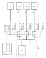
- FIG. 1 shows schematically the power supply system of a motor vehicle with a device according to the invention.
- an alternator 1 generator
- the alternator 1 outputs the power generated via corresponding lines to the electrical consumers in the motor vehicle.
- consumers are in the figure schematically an air conditioner 7a, an electric motor 7b, a light source 7c and other consumers 8 indicated.
- the power taken by all consumers of the alternator 1 must correspond in the time average of the power that the generator 1 can produce. Therefore, to prevent overloading the alternator 1, typically the power supply to the loads must be controlled.
- One possible way to do this is to subject power transmission to a load to pulse modulation.
- pulse modulation the power is transmitted in individual power pulses.
- the powers P a , P b , P c transferred to the consumers 7a, 7b, 7c jump in a rectangle between a maximum (corresponding to the full voltage of the generator) and a minimum of zero.
- Such a pulse modulation is particularly possible for consumers who represent resistive and inductive loads, so for example to control the dimming of light, the speed of an electric motor and the like. Consumers who can not or should not be supplied with pulse modulation are summarized in the figure in block 8. They play no further role in the context of the present invention.
- the pulse width modulation in which the width of the pulses is varied.
- the width of a power pulse (“voltage-on")
- the width of the gaps between two power pulses (“voltage-off")
- the magnitude of the average power transmitted can be set. Since the power to be provided by the alternator 1 to the consumers 7a, 7b, 7c corresponds to the sum of the individual powers, the mean load of the generator 1 can also be regulated by the pulse modulation.
- a coordination of the pulse modulations on the lines 6a, 6b, 6c to the consumers 7a, 7b, 7c made.
- the pulse modulations are synchronized or coordinated so that as shown in the figure whenever possible only one power pulse is generated at a given time, the power pulses on the services 6a, 6b, 6c so do not overlap or as little as possible.
- the power extraction from the generator 1 can be distributed as evenly as possible over time, so that the load peaks decrease accordingly.
- the power pulses of the individual transmitted power P a , P b , P c are lined up just completely, so that for the generator 1, a total power output P tot (without consideration of the consumer 8) results, in which the peak power is lowered to a minimum. Accordingly, the battery 2 is required to a minimum extent (ideally not at all), which increases its life accordingly.
- a power control of the type described above is particularly interesting for consumers such as loads from air conditioners, which have relatively long time constants and a potential for a flexible control.
- the technical implementation of the method described above includes a device 9 with an input for the current source 1, outputs 6a, 6b, 6c for the connection of the consumers, and separate driver circuits 5a, 5b, 5c for each of the pulse width modulated supplied consumers 7a, 7b, 7c.
- the driver circuits are all connected to the alternator 1 and generate at their output lines 6a, 6b, 6c each pulse width modulated powers P a , P b , P c .
- the driver circuits 5a, 5b, 5c may be spatially distributed at different locations in the motor vehicle, but they may also be implemented centrally in a single module.
- the driver circuits 5a, 5b, 5c are further connected to a communication bus 4 (for example LIN, CAN - Controller Area Network). Also connected to the bus 4 is a device 9 belonging to the synchronization circuit 3, which outputs a synchronization signal Syn on the bus 4. This sync signal Syn can then be used by the driver circuits 5a, 5b, 5c to coordinate their pulse modulations in the manner proposed.
- a communication bus 4 for example LIN, CAN - Controller Area Network
- the amplitude maximum of the total power P tot to be provided by the alternator 1 is 90 watts.
- the power maximum would be 240 watts.
- the synchronization signal Syn of the synchronization circuit 3 may include more than the illustrated three identifiers.
- the number of identifiers can be fixed or adjusted depending on the situation.
- the synchronization signals may be overlapping for different loads.
- the frequency of the signals may be fixed or varied according to the strategy.
Landscapes
- Engineering & Computer Science (AREA)
- Power Engineering (AREA)
- Electric Propulsion And Braking For Vehicles (AREA)
Claims (5)
- Dispositif (9) pour commander l'alimentation de charges (7a, 7b, 7c) en puissance électrique (Pa, Pb, Pc) à partir d'une source de courant (1), comprenant une entrée pour le raccordement d'une source de courant (1) ainsi qu'au moins deux sorties (6a, 6b, 6c) pour le raccordement de charges (7a, 7b, 7c), ce dispositif étant configuré pour mettre à disposition les puissances (Pa, Pb, Pc) aux sorties (6a, 6b, 6c) à chaque fois modulées par impulsions, les modulations par impulsions sur au moins une première et une deuxième des sorties (6a, 6b, 6c) étant coordonnées de telle sorte qu'il existe un premier intervalle de temps pendant lequel seule la première des deux sorties (6a, 6b) reçoit une impulsion de puissance et qu'il existe un deuxième intervalle de temps pendant lequel seule la deuxième des deux sorties (6c) reçoit une impulsion de puissance,
caractérisé en ce que
le dispositif (9) comprend pour chaque sortie (6a, 6b, 6c) un circuit d'attaque (5a, 5b, 5c) qui génère, à partir d'une puissance (Pges) mise à disposition à l'entrée du dispositif, une puissance de sortie modulée par impulsions (Pa, Pb, Pc) sur la sortie (6a, 6b, 6c) correspondante, le dispositif (9) comprenant un circuit de synchronisation (3) qui est relié avec les circuits d'attaque (5a, 5b, 5c) et met à disposition de ceux-ci un signal de synchronisation (Syn), ce signal de synchronisation (Syn) contenant une séquence dans le temps d'identificateurs (A, B, C) et les circuits d'attaque (5a, 5b, 5c) étant conçus pour réagir différemment aux identificateurs. - Dispositif selon la revendication 1, caractérisé en ce que celui-ci est configuré de telle sorte que la coordination des modulations par impulsions s'effectue pour toutes les paires de charges (7a, 7b, 7c).
- Dispositif selon la revendication 1 ou 2, caractérisé en ce que celui-ci est configuré de telle sorte que les modulations par impulsions de toutes les puissances (Pa, Pb, Pc) transmises sont coordonnées de manière à ce que la puissance (Pges) maximale prélevée de la source de courant (1) soit la plus faible possible.
- Dispositif selon au moins l'une des revendications 1 à 3, caractérisé en ce que celui-ci est configuré de telle sorte que les modulations par impulsions de toutes les puissances (Pa, Pb, Pc) transmises sont coordonnées de manière à ce qu'à chaque instant, au maximum une charge (7a, 7b, 7c) reçoive une impulsions de puissance.
- Dispositif selon au moins l'une des revendications 1 à 4, caractérisé en ce que celui-ci est configuré de telle sorte que les modulations par impulsions varient à chaque fois de manière rectangulaire entre une amplitude maximale prédéfinie et zéro.
Priority Applications (2)
| Application Number | Priority Date | Filing Date | Title |
|---|---|---|---|
| DE50313206T DE50313206D1 (de) | 2003-08-26 | 2003-08-26 | Einrichtung und Verfahren zur Steuerung der Versorgung von elektrischen Verbrauchern |
| EP20030103224 EP1511150B1 (fr) | 2003-08-26 | 2003-08-26 | Procédé et dispositif pour commander l'alimentation de consommateurs éléctriques |
Applications Claiming Priority (1)
| Application Number | Priority Date | Filing Date | Title |
|---|---|---|---|
| EP20030103224 EP1511150B1 (fr) | 2003-08-26 | 2003-08-26 | Procédé et dispositif pour commander l'alimentation de consommateurs éléctriques |
Publications (2)
| Publication Number | Publication Date |
|---|---|
| EP1511150A1 EP1511150A1 (fr) | 2005-03-02 |
| EP1511150B1 true EP1511150B1 (fr) | 2010-10-20 |
Family
ID=34089732
Family Applications (1)
| Application Number | Title | Priority Date | Filing Date |
|---|---|---|---|
| EP20030103224 Expired - Lifetime EP1511150B1 (fr) | 2003-08-26 | 2003-08-26 | Procédé et dispositif pour commander l'alimentation de consommateurs éléctriques |
Country Status (2)
| Country | Link |
|---|---|
| EP (1) | EP1511150B1 (fr) |
| DE (1) | DE50313206D1 (fr) |
Families Citing this family (4)
| Publication number | Priority date | Publication date | Assignee | Title |
|---|---|---|---|---|
| AT509441B1 (de) | 2010-02-08 | 2015-08-15 | MAN Truck & Bus Österreich AG | Regelung von zwei generatoren eines kraftfahrzeug-stromkreises |
| DE102010049800A1 (de) | 2010-07-01 | 2012-01-05 | Dbk David + Baader Gmbh | Elektronisches Ansteuersystem zur Steuerung der Leistungsaufnahme mehrerer elektrischer Verbraucher |
| US9584015B2 (en) | 2012-11-29 | 2017-02-28 | Telefonaktiebolaget Lm Ericsson (Publ) | Determination of phase offsets in a power supply system having multiple switching converters |
| EP2784895B1 (fr) * | 2014-04-03 | 2016-03-23 | ABB Technology AG | Dispositif de commande pour un système de distribution d'énergie et procédé de commande d'un système de distribution d'énergie |
Family Cites Families (3)
| Publication number | Priority date | Publication date | Assignee | Title |
|---|---|---|---|---|
| DE3422300A1 (de) * | 1984-06-15 | 1985-12-19 | Walter 3000 Hannover Rosch | Elektrische schaltung fuer stromverbraucher |
| DE3539581A1 (de) * | 1985-11-08 | 1987-05-21 | Philips Patentverwaltung | Verfahren zum steuern mehrerer elektrischer lasten |
| DE19955406A1 (de) | 1999-11-18 | 2001-05-23 | Vb Autobatterie Gmbh | Verfahren zur Steuerung von mehreren gleichzeitig von einer Stromquelle betriebenen elektrischen Verbrauchern |
-
2003
- 2003-08-26 EP EP20030103224 patent/EP1511150B1/fr not_active Expired - Lifetime
- 2003-08-26 DE DE50313206T patent/DE50313206D1/de not_active Expired - Lifetime
Also Published As
| Publication number | Publication date |
|---|---|
| DE50313206D1 (de) | 2010-12-02 |
| EP1511150A1 (fr) | 2005-03-02 |
Similar Documents
| Publication | Publication Date | Title |
|---|---|---|
| DE19857645B4 (de) | Elektrisches System für Elektrofahrzeug | |
| DE69519984T2 (de) | Steuerungssystem für elektrische Fahrzeuge | |
| WO1999041816A1 (fr) | Procedes et dispositifs de fonctionnement en parallele commande de transformateurs de tension continue | |
| EP0685940A1 (fr) | Convertisseur à commutation avec modulation d'impulsions en durée pour charges électriques | |
| DE102013201489A1 (de) | Batterie mit mehreren Batteriezellen sowie Verfahren zur Regelung einer Batteriespannung einer Batterie über Einschaltwahrscheinlichkeiten der Batteriezellen | |
| DE102020118886A1 (de) | Verfahren zur Ansteuerung von elektrischen Maschinen | |
| DE19709767C1 (de) | Verfahren zum Ansteuern mehrerer Schaltendstufen, Ansteuereinrichtung und Leistungsverstärker | |
| EP3760511A1 (fr) | Procédé de fonctionnement d'un véhicule | |
| EP4252340A1 (fr) | Agencement de convertisseur cc, système électrique embarqué pour véhicule électrique et procédé de fonctionnement d'un agencement de convertisseur cc | |
| DE102009026612A1 (de) | Ansteuerung eines Verbrauchers mit einem Rauschsignal | |
| EP1511150A1 (fr) | Procédé et dispositif pour commander l'alimentation de consommateurs éléctriques | |
| EP4472860B1 (fr) | Procédé d'opération d'un ensemble attelé de véhicule utilitaire et ensemble attelé de véhicule utilitaire | |
| DE10227253A1 (de) | Vorrichtung zum Betreiben eines Magnetfahrzeugs | |
| DE102010040608B4 (de) | Digitaler Zeitmultiplexenergieregler | |
| DE102021129953B3 (de) | Multikompatibler Stromrichter, Verfahren zum Betrieb eines Stromrichters, Antriebssystem und elektrisch angetriebene Vorrichtung | |
| EP3890177B1 (fr) | Dispositif de commande pour un convertisseur indirect et un convertisseur indirect | |
| DE102022201511B4 (de) | Verfahren zur Ansteuerung von Leistungshalbleitern eines Inverters, Computerprogramm, Vorrichtung zur Datenverarbeitung, Inverter, Elektroantrieb sowie Fahrzeug | |
| DE102020124496A1 (de) | Verfahren zum Betreiben von wenigstens zwei mit einem Gleichstromnetzwerk verbundenen Wechselrichtern und Kraftfahrzeug | |
| DE10338159B4 (de) | Spannungsversorgungseinrichtung und Verfahren zur Spannungserzeugung in einem Kraftfahrzeug | |
| EP2217039B1 (fr) | Procédé de commande à largeurs d'impulsions modulées de plusieurs consommateurs électriques | |
| DE102019125293A1 (de) | Gleichspannungswandlung in einem Bordnetz | |
| AT525897B1 (de) | Verfahren und System zum Optimieren der Systemeffizienz eines elektrischen Antriebssystems eines Kraftfahrzeugs | |
| DE102023210240A1 (de) | Verfahren zum Betreiben mehrerer parallel geschalteter aktiver Gleichrichter | |
| EP1609236B1 (fr) | Procede et unite de commande pour commander des moteurs ventiles | |
| EP3650259A1 (fr) | Procédé de fonctionnement d'un véhicule automobile et véhicule automobile |
Legal Events
| Date | Code | Title | Description |
|---|---|---|---|
| PUAI | Public reference made under article 153(3) epc to a published international application that has entered the european phase |
Free format text: ORIGINAL CODE: 0009012 |
|
| AK | Designated contracting states |
Kind code of ref document: A1 Designated state(s): AT BE BG CH CY CZ DE DK EE ES FI FR GB GR HU IE IT LI LU MC NL PT RO SE SI SK TR |
|
| AX | Request for extension of the european patent |
Extension state: AL LT LV MK |
|
| 17P | Request for examination filed |
Effective date: 20050902 |
|
| AKX | Designation fees paid |
Designated state(s): DE FR GB |
|
| 17Q | First examination report despatched |
Effective date: 20091202 |
|
| GRAP | Despatch of communication of intention to grant a patent |
Free format text: ORIGINAL CODE: EPIDOSNIGR1 |
|
| GRAC | Information related to communication of intention to grant a patent modified |
Free format text: ORIGINAL CODE: EPIDOSCIGR1 |
|
| GRAS | Grant fee paid |
Free format text: ORIGINAL CODE: EPIDOSNIGR3 |
|
| GRAA | (expected) grant |
Free format text: ORIGINAL CODE: 0009210 |
|
| RAP1 | Party data changed (applicant data changed or rights of an application transferred) |
Owner name: FORD GLOBAL TECHNOLOGIES, LLC, A SUBSIDARY OF FORD |
|
| AK | Designated contracting states |
Kind code of ref document: B1 Designated state(s): DE FR GB |
|
| REG | Reference to a national code |
Ref country code: GB Ref legal event code: FG4D Free format text: NOT ENGLISH |
|
| REF | Corresponds to: |
Ref document number: 50313206 Country of ref document: DE Date of ref document: 20101202 Kind code of ref document: P |
|
| PLBE | No opposition filed within time limit |
Free format text: ORIGINAL CODE: 0009261 |
|
| STAA | Information on the status of an ep patent application or granted ep patent |
Free format text: STATUS: NO OPPOSITION FILED WITHIN TIME LIMIT |
|
| 26N | No opposition filed |
Effective date: 20110721 |
|
| REG | Reference to a national code |
Ref country code: DE Ref legal event code: R097 Ref document number: 50313206 Country of ref document: DE Effective date: 20110721 |
|
| PGFP | Annual fee paid to national office [announced via postgrant information from national office to epo] |
Ref country code: GB Payment date: 20110826 Year of fee payment: 9 Ref country code: FR Payment date: 20110901 Year of fee payment: 9 Ref country code: DE Payment date: 20110831 Year of fee payment: 9 |
|
| GBPC | Gb: european patent ceased through non-payment of renewal fee |
Effective date: 20120826 |
|
| REG | Reference to a national code |
Ref country code: FR Ref legal event code: ST Effective date: 20130430 |
|
| PG25 | Lapsed in a contracting state [announced via postgrant information from national office to epo] |
Ref country code: GB Free format text: LAPSE BECAUSE OF NON-PAYMENT OF DUE FEES Effective date: 20120826 Ref country code: DE Free format text: LAPSE BECAUSE OF NON-PAYMENT OF DUE FEES Effective date: 20130301 |
|
| PG25 | Lapsed in a contracting state [announced via postgrant information from national office to epo] |
Ref country code: FR Free format text: LAPSE BECAUSE OF NON-PAYMENT OF DUE FEES Effective date: 20120831 |
|
| REG | Reference to a national code |
Ref country code: DE Ref legal event code: R119 Ref document number: 50313206 Country of ref document: DE Effective date: 20130301 |