EP1511103A2 - Polymer electrolyte fuel cell - Google Patents
Polymer electrolyte fuel cell Download PDFInfo
- Publication number
- EP1511103A2 EP1511103A2 EP04019698A EP04019698A EP1511103A2 EP 1511103 A2 EP1511103 A2 EP 1511103A2 EP 04019698 A EP04019698 A EP 04019698A EP 04019698 A EP04019698 A EP 04019698A EP 1511103 A2 EP1511103 A2 EP 1511103A2
- Authority
- EP
- European Patent Office
- Prior art keywords
- polymer electrolyte
- mea
- gasket
- gap
- pair
- Prior art date
- Legal status (The legal status is an assumption and is not a legal conclusion. Google has not performed a legal analysis and makes no representation as to the accuracy of the status listed.)
- Granted
Links
Images






Classifications
-
- H—ELECTRICITY
- H01—ELECTRIC ELEMENTS
- H01M—PROCESSES OR MEANS, e.g. BATTERIES, FOR THE DIRECT CONVERSION OF CHEMICAL ENERGY INTO ELECTRICAL ENERGY
- H01M8/00—Fuel cells; Manufacture thereof
- H01M8/02—Details
-
- H—ELECTRICITY
- H01—ELECTRIC ELEMENTS
- H01M—PROCESSES OR MEANS, e.g. BATTERIES, FOR THE DIRECT CONVERSION OF CHEMICAL ENERGY INTO ELECTRICAL ENERGY
- H01M8/00—Fuel cells; Manufacture thereof
- H01M8/10—Fuel cells with solid electrolytes
- H01M8/1004—Fuel cells with solid electrolytes characterised by membrane-electrode assemblies [MEA]
-
- H—ELECTRICITY
- H01—ELECTRIC ELEMENTS
- H01M—PROCESSES OR MEANS, e.g. BATTERIES, FOR THE DIRECT CONVERSION OF CHEMICAL ENERGY INTO ELECTRICAL ENERGY
- H01M8/00—Fuel cells; Manufacture thereof
- H01M8/02—Details
- H01M8/0202—Collectors; Separators, e.g. bipolar separators; Interconnectors
- H01M8/0258—Collectors; Separators, e.g. bipolar separators; Interconnectors characterised by the configuration of channels, e.g. by the flow field of the reactant or coolant
- H01M8/0263—Collectors; Separators, e.g. bipolar separators; Interconnectors characterised by the configuration of channels, e.g. by the flow field of the reactant or coolant having meandering or serpentine paths
-
- H—ELECTRICITY
- H01—ELECTRIC ELEMENTS
- H01M—PROCESSES OR MEANS, e.g. BATTERIES, FOR THE DIRECT CONVERSION OF CHEMICAL ENERGY INTO ELECTRICAL ENERGY
- H01M8/00—Fuel cells; Manufacture thereof
- H01M8/02—Details
- H01M8/0271—Sealing or supporting means around electrodes, matrices or membranes
- H01M8/0273—Sealing or supporting means around electrodes, matrices or membranes with sealing or supporting means in the form of a frame
-
- H—ELECTRICITY
- H01—ELECTRIC ELEMENTS
- H01M—PROCESSES OR MEANS, e.g. BATTERIES, FOR THE DIRECT CONVERSION OF CHEMICAL ENERGY INTO ELECTRICAL ENERGY
- H01M8/00—Fuel cells; Manufacture thereof
- H01M8/02—Details
- H01M8/0271—Sealing or supporting means around electrodes, matrices or membranes
- H01M8/0276—Sealing means characterised by their form
-
- H—ELECTRICITY
- H01—ELECTRIC ELEMENTS
- H01M—PROCESSES OR MEANS, e.g. BATTERIES, FOR THE DIRECT CONVERSION OF CHEMICAL ENERGY INTO ELECTRICAL ENERGY
- H01M8/00—Fuel cells; Manufacture thereof
- H01M8/02—Details
- H01M8/0271—Sealing or supporting means around electrodes, matrices or membranes
- H01M8/0276—Sealing means characterised by their form
- H01M8/0278—O-rings
-
- H—ELECTRICITY
- H01—ELECTRIC ELEMENTS
- H01M—PROCESSES OR MEANS, e.g. BATTERIES, FOR THE DIRECT CONVERSION OF CHEMICAL ENERGY INTO ELECTRICAL ENERGY
- H01M8/00—Fuel cells; Manufacture thereof
- H01M8/10—Fuel cells with solid electrolytes
-
- H—ELECTRICITY
- H01—ELECTRIC ELEMENTS
- H01M—PROCESSES OR MEANS, e.g. BATTERIES, FOR THE DIRECT CONVERSION OF CHEMICAL ENERGY INTO ELECTRICAL ENERGY
- H01M8/00—Fuel cells; Manufacture thereof
- H01M8/24—Grouping of fuel cells, e.g. stacking of fuel cells
- H01M8/241—Grouping of fuel cells, e.g. stacking of fuel cells with solid or matrix-supported electrolytes
-
- H—ELECTRICITY
- H01—ELECTRIC ELEMENTS
- H01M—PROCESSES OR MEANS, e.g. BATTERIES, FOR THE DIRECT CONVERSION OF CHEMICAL ENERGY INTO ELECTRICAL ENERGY
- H01M8/00—Fuel cells; Manufacture thereof
- H01M8/24—Grouping of fuel cells, e.g. stacking of fuel cells
- H01M8/2465—Details of groupings of fuel cells
- H01M8/2483—Details of groupings of fuel cells characterised by internal manifolds
-
- Y—GENERAL TAGGING OF NEW TECHNOLOGICAL DEVELOPMENTS; GENERAL TAGGING OF CROSS-SECTIONAL TECHNOLOGIES SPANNING OVER SEVERAL SECTIONS OF THE IPC; TECHNICAL SUBJECTS COVERED BY FORMER USPC CROSS-REFERENCE ART COLLECTIONS [XRACs] AND DIGESTS
- Y02—TECHNOLOGIES OR APPLICATIONS FOR MITIGATION OR ADAPTATION AGAINST CLIMATE CHANGE
- Y02E—REDUCTION OF GREENHOUSE GAS [GHG] EMISSIONS, RELATED TO ENERGY GENERATION, TRANSMISSION OR DISTRIBUTION
- Y02E60/00—Enabling technologies; Technologies with a potential or indirect contribution to GHG emissions mitigation
- Y02E60/30—Hydrogen technology
- Y02E60/50—Fuel cells
Definitions
- the present invention relates to a structure of a polymer electrolyte fuel cell. More particularly, the present invention relates to a stack assembly structure of a membrane electrode assembly (MEA), gaskets, and electrically conductive separators.
- MEA membrane electrode assembly
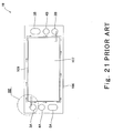
- Fig. 21 is a plan view showing a structure of an assembly comprising a polymer electrolyte membrane electrode assembly which is the conventional basic power generation element and a gasket 106.
- the polymer electrolyte membrane electrode assembly is called a MEA (membrane electrode assembly).
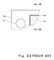
- Fig, 22 is a partially enlarged plan view showing a structure of a portion represented by XXII in Fig. 21.
- Fig. 23 is a cross-sectional view taken along line XXIII - XXIII in Fig. 22.
- a MEA 15 comprises a polymer electrolyte membrane 12 formed by an ion-permeable membrane that selectively passes hydrogen ions, a pair of catalyst layers (cathode catalyst layer 13 and anode catalyst layer 14) disposed to interpose the membrane 12 between them and containing carbon powders carrying platinum-group metal catalyst as major component, and a pair of gas diffusion electrodes 107 provided on outer surfaces of the pair of catalyst layers 13 and 14 to be located inward relative to the outer periphery of the polymer electrolyte membrane 12.
- the gas diffusion electrodes 107 are formed chiefly by carbon fibers having both gas permeability and electron conductivity.
- a pair of gaskets 106 are provided on peripheral portions of surfaces on both sides of the MEA 15 so as to have gaps 109 between the gaskets 106 and the gas diffusion electrodes 107.
- the MEA 15 and the gaskets 106 are joined to each other typically by thermocompression bonding process.
- the MEA 15 provided with the gaskets 106 is called a MEA-gasket assembly.
- a width of the gaps 109 between the gas diffusion electrodes 107 of the MEA 15 and the gaskets 106 is typically approximately 0.2 to 0.5mm. The provision of the gaps 109 permits displacement between the gas diffusion electrodes 107 and the gaskets 106, thereby facilitating assembling these.
- Basic principle of the above conventional polymer electrolyte fuel cell is such that one principal surface of the polymer electrolyte membrane 12 is exposed to the fuel gas and the other principal surface thereof is exposed to the oxidizing gas such as air so that chemical reaction occurs in the vicinity of the membrane 12 to generate water, and the resulting reaction energy is electrically taken out.
- a fuel gas supply manifold hole 3A and a fuel gas discharge manifold hole 3B are formed to be opposed in peripheral portion of the MEA-gasket assembly. And, one surface of the anode-side electrically conductive separator (see Fig. 4) provided with a fuel gas passage on a surface thereof is in contact with the principal surface (surface shown in Fig. 21) of the MEA-gasket assembly exposed to the fuel gas. As represented by a broken line in Fig.
- the fuel gas supply manifold hole 3A and the fuel gas discharge manifold hole 3B of the MEA-gasket assembly are connected to each other through the fuel gas passage.
- the fuel gas passage and the gap 109 cross each other so as to fluidically communicate with each other.
- a part of the gas flowing from the fuel gas supply manifold hole 3A into the fuel gas passage flows through the gap 109 and into the fuel gas discharge manifold hole 3B.
- the fuel gas flowing through the gap 109 is discharged without being exposed to the gas diffusion electrode 107.
- one surface of the cathode-side electrically conductive separator (see Fig. 3) provided with an oxidizing gas passage on a surface thereof is in contact with the principal surface of the MEA-gasket assembly exposed to the oxidizing gas.
- a part of the gas flowing from the oxidizing gas supply manifold hole 5A into the oxidizing gas passage flows through the gap 109 and into the oxidizing gas discharge manifold hole 5B.
- the presence of the cell reaction gases which are not exposed to the gas diffusion electrodes 107 reduces utilization ratio of these gases and hence reduces power generation efficiency.
- the conventional polymer electrolyte fuel cell is required to increase utilization ratio of the cell reaction gases.
- a fastening device of the cell becomes large-sized because of a need for a considerably large force for fastening the cells of the fuel cell.
- the gaskets are made of a material such as liquid EPDM or rubber which is highly elastic and highly durable with respect to temperature variation or reactive materials, a manufacturing cost of the fuel cell substantially increases.
- the present invention has been developed under the circumstances, and an object of the present invention is to provide a polymer electrolyte fuel cell capable of simply increasing utilization ratio of cell reaction gases.
- a polymer electrolyte fuel cell comprising a MEA-gasket assembly including a MEA having a polymer electrolyte membrane, a pair of catalyst layers that sandwich the polymer electrolyte membrane between the catalyst layers, and a pair of gas diffusion electrodes provided on outer surfaces of the pair of catalyst layers to be located inward relative to an outer periphery of the polymer electrolyte membrane, and a pair of gaskets provided on peripheral portions of surfaces of both sides of the MEA with gaps between the gaskets and the gas diffusion electrodes; and a pair of electrically conductive separators disposed to sandwich the MEA-gasket assembly and provided with groove-shaped cell reaction gas passages on inner surfaces thereof, each of the cell reaction gas passages running sequentially on a corresponding gasket of the pair of gaskets, a corresponding gap of the gaps, a corresponding gas diffusion electrode of the pair of gas diffusion electrodes, the corresponding gap, and the corresponding gasket, wherein each of the gaps is
- the closing means may be configured to cause an inner periphery of the gasket to partially contact an outer periphery of the gas diffusion electrode.
- the closing means may be configured to cause the inner periphery of the gasket to partially contact the outer periphery of the gas diffusion electrode in such a manner that the inner periphery of the gasket is partially overlapped with the outer periphery of the gas diffusion electrode, and the electrically conductive separator is brought into contact with an outer surface of the MEA-gasket assembly to allow the overlapped portion of the gas diffusion electrode to be crushed.
- the closing means may be configured to partially close the gap by plastic-deformed plastic body.
- the plastic body may be made of thermoplastic resin.
- the gap may be closed in such a manner that the plastic body is disposed in an enlarged width portion formed on the gap and is plastic-deformed to fill the enlarged width portion of the gap.
- the closing means may be configured to partially close the gap by elastically deformed elastic body.
- the gap may be closed in such a manner that the elastic body is fitted in an elastic body storage hole provided at a position of an inner surface of the electrically conductive separator corresponding to an enlarged width portion formed on the gap, and the inner surface of the electrically conductive separator is brought into contact with the outer surface of the MEA-gasket assembly to allow the elastic body to be fitted in the enlarged width portion of the gap.
- a polymer electrolyte fuel cell comprising a MEA-gasket assembly including a MEA having a polymer electrolyte membrane, a pair of catalyst layers that sandwich the polymer electrolyte membrane between the catalyst layers, and a pair of gas diffusion electrodes provided on outer surfaces of the pair of catalyst layers to be located inward relative to an outer periphery of the polymer electrolyte membrane, and a pair of gaskets disposed on peripheral portions of surfaces of both sides of the MEA with gaps between the gaskets and the gas diffusion electrodes; and a pair of electrically conductive separators disposed to sandwich the MEA-gasket assembly and provided with groove-shaped cell reaction gas passages on inner surfaces thereof, each of the cell reaction gas passages running sequentially on a corresponding gasket of the pair of gaskets, a corresponding gap of the gaps, a corresponding gas diffusion electrode of the pair of gas diffusion electrodes, the corresponding gap, and the corresponding gasket, wherein each of the gaps
- the gap may be bent in rectangular wave shape, triangular wave shape, or shapes other than straight line.
- Fig. 1 is a exploded perspective view showing a structure of a polymer electrolyte fuel cell according to a first embodiment of the present invention.
- a stack structure of the polymer electrolyte fuel cell is partially exploded for the sake of convenience.
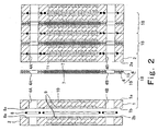
- Fig. 2 is a cross-sectional view taken along line II-II in Fig. 1.
- a stack structure of the polymer electrolyte fuel cell is exploded for the sake of convenience.
- the polymer electrolyte fuel cell is formed by stacked cells 18 (unit cells: see Fig. 2).
- the cell 18 is structured such that a MEA (membrane electrode assembly)-gasket assembly 19 is sandwiched between a cathode-side electrically conductive separator (hereinafter referred to as a cathode separator) 1 and an anode-side electrically conductive separator (hereinafter referred to as an anode separator) 2.
- a MEA membrane electrode assembly
- an anode separator anode separator
- the above-constructed cells 18 are stacked with O-rings (water cooling surface seal members )8 sandwiched between them, and the stacked cells 18 are sandwiched between end plates (not shown) on both ends with current collecting plates (not shown) and insulating plates (not shown) interposed between the stacked cells 18 and the end plates, and fastened by fastening bolts (not shown) from the both ends.
- a stack which forms a main portion of the polymer electrolyte fuel cell.
- this stack is provided with a fuel gas supply manifold 3A' and a fuel gas discharge manifold 3B' respectively formed by the fuel gas supply manifold holes 3A and the fuel gas discharge manifold holes 3B, an oxidizing gas supply manifold 5A' and an oxidizing gas discharge manifold 5B' respectively formed by the oxidizing gas supply manifold holes 5A and the oxidizing gas discharge manifold holes 5B, and a water supply manifold 4A' and a water discharge manifold 4B' respectively formed by the water supply manifold holes 4A and the water discharge manifold holes 4B to be opposed in the peripheral portion.
- These manifolds 3A' and 3B', 5A' and 5B', and 4A' and 4B' penetrate the stack in the direction in which the cells 18 are stacked.
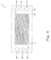
- Fig. 3 is a plan view showing a pattern of the oxidizing gas passage of the cathode separator 1 and Fig. 4 is a plan view showing a pattern of the fuel gas passage of the anode separator 2.
- an oxidizing gas passage 10 is formed on one principal surface (inner surface) 1a of the cathode separator 1 which contacts the MEA 15.
- the oxidizing gas passage 10 is formed by grooves and configured to connect the oxidizing gas supply manifold hole 5A and the oxidizing gas discharge manifold hole 5B to each other.
- a cooling water passage 9 (not shown in Fig. 3) is formed on the other principal surface (outer surface) 1b of the cathode separator 1.
- the cooling water passage 9 is formed by grooves and configured to connect the water supply manifold hole 4A and the water discharge manifold hole 4B.
- O-ring storage grooves 8a are formed at appropriate positions of the outer surfaces 1b to store the O-rings 8 (see Fig. 2).
- a fuel gas passage 11 is formed on a principal surface (inner surface) 2a of the anode separator 2 which contacts the MEA 15.
- the fuel gas passage 11 is formed by grooves and configured to connect the fuel gas supply manifold hole 3A and the fuel gas discharge manifold hole 3B.
- a cooling water passage 9 (not shown in Fig. 4) is formed on the other principal surface (outer surface) 2b of the anode separator 2.
- the cooling water passage 9 is formed by grooves and configured to connect the water supply manifold hole 4A and the water discharge manifold hole 4B.
- O-ring storage grooves 8a are formed at appropriate positions of the outer surface 2b to store the O-rings 8 (see Fig. 2).
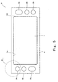
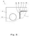
- Fig. 5 is a plan view showing a structure of the MEA-gasket assembly 19 and Fig. 6 is a partially enlarged plan view showing a portion represented by VI in Fig. 5.
- the MEA-gasket assembly 19 is basically identical to the MEA-gasket assembly already described in the Description of the Related Art except for a structure of the gap 109 between the gasket 6 and the gas diffusion electrode 7. Therefore, the MEA-gasket assembly 19 will not be further described in detail.
- annular (rectangular and annular) gasket 6 is provided on a peripheral portion of the polymer electrolyte membrane 12 (not shown) provided with the catalyst layer 14 (not shown).
- the gas diffusion electrode layer 7 is provided on an outer surface of the catalyst layer 14 exposed to a hollow portion of the annular gasket 6 to be located inward relative to the outer periphery of the polymer electrolyte membrane 12.
- the catalyst layer 13 is formed, the gasket 6 and the gas diffusion electrode 7 are provided on an opposite surface of the polymer electrolyte membrane 12, i.e., the principal surface of the polymer electrolyte membrane 12 on the oxidizing gas side, although not shown. And, these are joined by thermocompression bonding process, thereby forming the MEA-gasket assembly 19 (see Fig. 23).
- the annular gap 109 is formed between the gasket 6 and the gas diffusion electrode 7.
- a portion (hereinafter referred to as a gap closing portion) 110 is formed to close the gap 109 between the gas diffusion electrode 7 and the gasket 6.
- the gap closing portion 110 is a feature of the present invention. Specifically, the gap closing portion 110 is formed in such a manner that a part of an inner periphery 6a of the gasket 6 and a part of an outer periphery of the gas diffusion electrode 7 come in contact with each other, when the pair of gas diffusion electrodes 7 are provided on the outer surfaces of the pair of catalyst layers 13 and 14 exposed to the hollow portions of the gaskets 6.
- the gasket 6 is rectangular, and the inner periphery 6a of the gasket 6 is also rectangular.
- the cathode separator 1 and the anode separator 2 are brought into contact with the outer surfaces of the MEA-gasket assembly 19.
- portions of the corner portions 7a of the gas diffusion electrode 7 which are located on the triangular portions 6b of the gasket 6 are crushed, thereby causing the inner periphery 6a of the gasket 6 and the outer periphery of the gas diffusion electrode 7 to partially contact each other.
- the gas diffusion electrode 7 is chiefly formed by fragile carbon fibers and has a void percentage of 80 to 90%, the portions of the corner portions 7a of the gas diffusion electrode 7 which are located on the triangular portions 6b are easily crushed by a local load due to cell fastening force.
- the gap closing portion 110 is formed on the opposite surface in the same manner.
- a fuel gas e.g., hydrogen
- the fuel gas branches and flows into the fuel gas passage 11. While flowing through the fuel gas passage 11, the fuel gas contacts the MEA 15, permeates the gas diffusion electrode 7, and contacts the polymer electrolyte membrane 12 through the anode catalyst layer 14. Thereby, the fuel gas and the oxidizing gas react with each other and are consumed through a cell reaction. The extra fuel gas reaches the fuel gas discharge manifold 3B' and is discharged therefrom.
- the oxidizing gas e,g., air
- the oxidizing gas supply manifold 5A' the oxidizing gas branch and flows into the oxidizing gas passage 10 of the cathode separator 1. While flowing through the oxidizing gas passage 10, the oxidizing gas contacts the MEA 15, permeates the gas diffusion electrode 7, and contacts the polymer electrolyte membrane 12 through the cathode catalyst layer 13. Thereby, the fuel gas and the oxidizing gas react with each other and are consumed through a cell reaction. The extra oxidizing gas reaches the oxidizing gas discharge manifold 5B' and is discharged therefrom. During this time, cooling water supplied from the water supply manifold 4A' flows through the cooling water passage 9 and is discharged through the water discharge manifold 4B'. Consequently, the stack is cooled.
- the oxidizing gas e,g., air
- the MEA-gasket assembly 19 is provided with the gap closing portion 110, it is possible to inhibit the fuel gas from flowing from the fuel gas supply manifold 3A' to the fuel gas discharge manifold 3B' through the gap 109 between the gas diffusion electrode 7 and the gasket 6, and to inhibit the oxidizing gas from flowing from the oxidizing gas supply manifold 5A' to the oxidizing gas discharge manifold 5B' through the gap 109.
- the MEA-gasket assembly 19 in Figs. 5 and 6 was manufactured in the following process.
- ketjen black EC (FURNACE BLACK produced by ketjen Black International Co., Ltd) with 800m 2 /g of a specific surface area and 360ml/100g of DBP oil absorbing amount in a weight ration of 1:1. Then, 35g of water and 59g of alcohol dispersion liquid of hydrogen ion conductive polymer electrolyte (9%FSS produced by Asahi Garasu Co. Ltd) were mixed with 10g of catalyst powder, and were dispersed by ultrasonic agitator, thereby producing catalyst layer ink. And, the catalyst layer ink was applied to polypropylene film (TREPAN 50- 2500 produced by TORAY Co. Ltd) and dried, thereby forming the catalyst layers 13 and 14.
- the catalyst layers 13 and 14 were cut into pieces of 104 ⁇ 216mm, which were transferred to center portions of surfaces of both sides of the polymer electrolyte membrane 12 of 330 ⁇ 150mm (Nafion 117 produced by Dupon Co. Ltd: 5 ⁇ m thick) at a temperature of 135°C and a pressure of 32kgf/cm 2 .
- the sheet gasket was molded by Thomson Cutter mold to form the gasket 6 having a shape shown in Fig. 5. More specifically, the gasket 6 is sized to be 130 ⁇ 300mm, and has a hollow portion of 108 ⁇ 220mm provided with the triangular portions 6b at the four corners of the inner periphery 6a, and the above pairs of fuel gas, oxidizing gas, and water manifolds.
- carbon fiber cloth having a size of 107 ⁇ 219mm and thickness of 0.3mm (Carbel CL 300 manufactured by Japan Goretex Co. Ltd) was used.
- the gaskets 6 were disposed so that the catalyst layers 13 and 14 (not shown) at the center portions of the polymer electrolyte membrane 12 were positioned at the center portions of the gaskets 6.
- the gas diffusion electrodes 7 were provided on the outer surfaces of the catalyst layers 13 and 14 to be located inward relative to the outer periphery of the polymer electrolyte membrane 12. And, the four corner portions 7a of the gas diffusion electrodes 7 were caused to move over the triangular portions 6b provided at the four corner portions of the inner periphery 6a of the gasket 6. Under this condition, thermocompression bonding process was carried out at 130°C and at 2MPa for one minute, thereby forming the MEA-gasket assembly 19.
- the MEA-gasket assembly 19 with the gap 109 between the gasket 6 and the gas diffusion electrode 7 closed by the gap closing portion 110 was obtained.
- the corner portions 7a of the gas diffusion electrode 7 were formed into a thickness of approximately 45 ⁇ m by the thermocompression bonding process. Further, since in fastening the cells 18, the cathode separator 1 and the anode separator 2 were brought into contact with the outer surfaces of the MEA-gasket assembly 19 and thereby the corner portions 7a were crushed, the corner portions 7a did not impede gas sealing ability of the gaskets 6.
- the MEA-gasket assembly 19 was sandwiched between the cathode separator 1 and the anode separator 2 shaped as shown in Figs. 3 and 4(separators manufactured by machining from 3mm-thick Glassy Carbon produced by Tokai Carbon Co. Ltd, a water passage on the back surface thereof are omitted in the drawing), and fastened by using a fastening gig with a fastening force of 2.5 ton.
- a fastening gig with a fastening force of 2.5 ton.
- the above four-cell stacks were operated under a condition in which a cell temperature was 70°C, the fuel gas was pure hydrogen (hydrogen humidified to have a dew-point temperature of 70°C, fuel utilization ratio: 80%), and the oxidizing gas was air (air humidified to have a dew point temperature of 70°C, air utilization ratio: 40%), and a current-voltage characteristic was measured.
- the results are shown in Fig. 7. As shown in Fig. 7, comparing the result of the example 1 represented by a solid line and the result of the comparison 1 represented by a broken line, it was recognized that an output was increased on low current density side where less gases were supplied and hence power generation efficiency of the polymer electrolyte fuel cell was increased in the example 1 in contrast to the comparison 1.
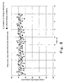
- Fig. 8 shows a state of pressure loss between the fuel gas supply manifold 3A' and the fuel gas discharge manifold 3B' in respective cells in a 80-cell stack.
- a variation in the pressure loss between the fuel gas supply manifold 3A' and the fuel gas discharge manifold 3B' between cells decreases in the example 1 as shown in Fig. 8.
- the reason is as follows. Since positioning the gas diffusion electrode 7 and the hollow portion of the gasket 6 is difficult in cell assembly process in the conventional example, the width of the gap 109 becomes non-uniform on the outer periphery of the gas diffusion electrode 7.
- the amount of the fuel gas flowing from the fuel gas supply manifold hole 3A to the fuel gas discharge manifold hole 3B through the gap 109 varies from cell to cell, and hence the pressure loss between the fuel gas supply manifold 3A' and the fuel gas discharge manifold 3B' varies from cell to cell.
- the pressure loss between the fuel gas supply manifold 3A' and the fuel gas discharge manifold 3B' varies less from cell to cell.
- Fig. 9 is a plan view showing a structure of a MEA-gasket assembly 19 of a polymer electrolyte fuel cell according to a second embodiment of the present invention.
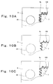
- Fig. 10A is a partially enlarged plan view showing a structure of a portion represented by X in Fig. 9.
- the same reference numerals as those in Figs. 5 and 6 denote the same or corresponding parts.
- the MEA-gasket assembly 19 of the second embodiment is substantially identical to that of the MEA-gasket assembly 19 of the first embodiment except for a structure of the gap 109 between the gasket 6 and the gas diffusion electrode 7.
- the gap 109 between the gasket 6 and the gas diffusion electrode 7 is formed in the shape of rectangular wave (6mm pitch ⁇ 50 turn). More specifically, the outer periphery of the gas diffusion electrode 7 is formed in convex and concave shape composed of continuous rectangles (6mm pitch ⁇ 50 turn).
- the gasket 6 has the inner periphery 6a formed in convex and concave shape composed of continuous rectangles and is disposed on the outer periphery of the gas diffusion electrode 7 such that the inner periphery 6a engage with the outer periphery of the electrode 7 with a predetermined gap.
- the inner periphery 6a of the gasket 6 is sized larger approximately 1mm than the outer periphery of the gas diffusion electrode 7 in the longitudinal and lateral directions.
- the gap 109 between the gasket 6 and the gas diffusion electrode 7 is approximately 0.5mm on average.
- the polymer electrolyte fuel cell constructed as described above since the polymer electrolyte membrane is required to contain sufficient water in order to gain desired cell performance in its operation principle, the fuel gas and the oxidizing gas contain water. For this reason, in an earlier stage of start of the fuel cell, a part of the fuel gas flows through the gap 109 between the gasket 6 and the gas diffusion electrode 7. But, since the gap 109 is formed in the shape of rectangular wave, water contained in the fuel gas remains in any bent portion of the gap 109 and thereby closes the gap 109 after an elapse of time, thereby causing the flow of the fuel gas to be blocked.
- the MEA-gasket assembly 19 shown in Fig. 9 and Fig. 10A was manufactured as in the example 1 of the first embodiment except for the shape of the gap 109.
- the comparison 1 used for comparison with the example 1 was re-manufactured and assembled into a four-cell stack, and the same characteristic test was carried out.
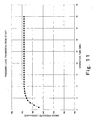
- the above four-cell stack comprising the MEA-gasket assembly 19 of the example 2 was operated under a condition in which the cell temperature was 70°C, the fuel gas was pure hydrogen (hydrogen humidified to have a dew-point temperature of 70°C, fuel utilization ratio: 80%), and the oxidizing gas was air (air humidified to have a dew point temperature of 70°C, air utilization ratio: 40%), and transition of the pressure loss between the fuel gas supply manifold 3A' and the fuel gas discharge manifold 3B' from the start of the operation was measured.
- the results are shown in Fig. 11. As shown in Fig.
- the pressure loss between the fuel gas supply manifold 3A' and the fuel gas discharge manifold 3B' gradually increases within 10 minutes from the start, and then reaches a stationary state. It is presumed that the behavior of the pressure loss is due to the fact that the water contained in the fuel gas closes the gap 109 between the gasket 6 and the gas diffusion electrode 7 after an elapse of time.
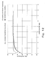
- Fig. 12 shows a re-start characteristic of the example 2.
- time required from start to rated operation in re-start was substantially equal to the time in first start, whereas, as apparent from Fig. 12, in the four-cell stack of the example 2, time required from start to rated operation in re-start was reduced in contrast to the conventional example.
- the polymer electrolyte fuel cell does not gain desired cell characteristic until the polymer electrolyte membrane contain sufficient water in its operation principle, and requires roughly several to several tens minutes from the start to the rated operation.
- the gap 109 between the gasket 6 and the gas diffusion electrode 7 is formed in wave shape, the gap 109 connecting the fuel gas supply manifold 3A and the fuel gas discharge manifold 3B, and the gap 109 connecting the oxidizing gas supply gas manifold 5A and the oxidizing gas discharge manifold hole 5B become long, and most of the water contained in the fuel gas remains in these gaps 109. It is presumed that in the example 2, the time required from the start to the rated operation in -restart of the polymer electrolyte fuel cell became shorter than the time required in the first start, because the polymer electrolyte membrane contains water stored in the gaps 109.
- Figs. 10B and 10C are partially enlarged plan views showing a structure of the X portion in Fig. 9 according to an alternative example 1 of the second embodiment.
- the gap 109 is formed in the shape of continuous triangular waves (6mm pitch ⁇ 50 turn).
- the gap 109 is formed in the shape of continuous circular arcs (6mm pitch ⁇ 50 turn).
- the gaps 109 formed in the shape of triangular wave and shapes other than straight line become long because of the presence of the bent portions, and most of the water contained in the fuel gas remains in the bent portions, similar effects are obtained.
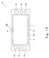
- Fig. 13 is a plan view showing a structure of a MEA-gasket assembly 19 of a polymer electrolyte fuel cell according to a third embodiment of the present invention.
- Fig. 14 is a partially enlarged plan view showing a structure of a portion represented by XIV in Fig. 13.
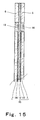
- Fig. 15 is a cross-sectional view taken along line XV-XV in Fig. 14.
- the same reference numerals as those in Figs. 5 and 6 denote the same or corresponding parts.
- the MEA-gasket assembly 19 of the third embodiment is substantially identical to that of the MEA-gasket assembly 19 of the first embodiment except for a structure of the gap 109 between the gasket 6 and the gas diffusion electrode 7.
- a detailed description of the MEA-gasket assembly 19 is omitted and difference between the first and third embodiments will be described.
- a plastic body 16 is provided in part of the gap 109 between the gasket 6 and the gas diffusion electrode 7 on the principal surface of the MEA-gasket assembly 19 on the fuel gas side.
- the gasket 6 is provided with a semicircular cut portion according to the size of the plastic body 16 on the inner periphery 6a at a position where the plastic body 16 is provided.
- the semicircular cut portion is hereinafter referred to as an enlarged width portion 16a of the gap 109.
- the plastic body 16 is provided in part of the gap 109 and the enlarged width portion 16a of the gap 109 is formed in the gasket 6 on the opposite surface of the MEA-gasket assembly 19, i.e., principal surface of the assembly 19 (not shown) on the oxidizing gas side.
- the MEA-gasket assembly 19 is manufactured by joining the polymer electrolyte membrane 12, the catalyst layers 13 and 14 provided on surfaces of both sides of the center portion of the polymer electrolyte membrane 12, the gas diffusion electrodes 7 disposed on the outer surfaces of the catalyst layers 13 and 14 to be located inward relative to the outer periphery of the polymer electrolyte membrane 12, the gaskets 6 provided on the peripheral portions of surfaces of both sides of the MEA 15 with the gaps 109, and plastic bodies 16 (closing means) disposed on the enlarged width portions 16a (not shown in Fig. 15) of the gaskets 6.
- the plastic bodies 16 are plastic-deformed to fill the enlarged width portions 16a of the gaps 109.
- the plastic bodies 16 are made of thermoplastic resin, and the MEA 15 and the gaskets 6 are subjected to thermocompression bonding process.
- the plastic bodies 16 are dissolved by the thermocompression bonding process and thereafter solidified to close the enlarged width portions 16a of the gaps 109 between the gaskets 6 and the gas diffusion electrodes 7.
- the plastic bodies 16 are disposed in the gap 109 on the principal surface of the MEA-gasket assembly 19 on the fuel gas side, it is possible to inhibit the fuel gas from flowing from the fuel gas supply manifold 3A' to the fuel gas discharge manifold 3B' through the gap 109.
- the plastic bodies 16 are disposed in the gap 109 on the principal surface of the MEA-gasket assembly 19 on the oxidizing gas side, it is possible to inhibit the oxidizing gas from flowing from the oxidizing gas supply manifold 5A' to the oxidizing gas discharge manifold 5B' through the gap 109.
- the MEA-gasket assembly 19 shown in Figs. 13 through 15 was manufactured in the following process.
- the catalyst layers 13 and 14 were transferred to the polymer electrolyte membrane 12 by the method of the example 1.
- the sheet gasket was molded by Thomson mold to form the gasket 6 having a shape shown in Fig. 13.
- the gasket 6 is sized to be 130 ⁇ 300mm, and has the inner periphery 6a of 108 ⁇ 220mm provided with semicircular cut portions, and the above pairs of manifold holes 3A, 3B, 4A, 4B, 5A, and 5B.
- the plastic body 16 was formed by polyethylene chip obtained by slicing polyethylene round bar with a diameter of 3mm to be 400 ⁇ m thick.
- the polyethylene chips 16 were dissolved and thereafter solidified to close the enlarged width portions 16a of the gaps 109 between the gaskets 6 and the gas diffusion electrodes 7.
- the MEA-gasket assembly 19 was assembled into a four-cell stack. A characteristic test was carried out as in the example 1. A desirable result was obtained.
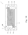
- Fig. 16 is a plan view showing a structure of the inner surface 1a of the cathode separator 1 of a polymer electrolyte fuel cell according to a fourth embodiment of the present invention.
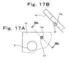
- Fig. 17A is a partially enlarged plan view showing a structure of a portion represented by XVII in Fig. 16, and
- Fig. 17B is a partially enlarged cross-sectional view showing the structure of the XVII portion.
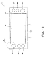
- Fig. 18 is a plan view showing a structure of a MEA-gasket assembly 19 of the polymer electrolyte fuel cell according to the fourth embodiment.
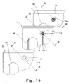
- Fig. 19 is a partially enlarged exploded perspective view showing a stack structure of the XIX portion in Fig.
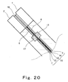
- Fig. 20 is a cross-sectional view taken along line XX - XX in Fig. 19 in fastening cells.
- Figs. 16 through 20 the same reference numerals as those in Figs. 5 and 6 denote the same or corresponding parts which will not be further described.
- the cathode separator 1 and the MEA-gasket assembly 19 of the fourth embodiment are substantially identical to those described in the first embodiment except for structures of the inner surface 1a of the cathode separator 1 and the gap 109 between the gasket 6 and the gas diffusion electrode 7.
- a detailed description of the cathode separator 1 and the MEA-gasket assembly 19 is omitted, and the difference between the first embodiment and the fourth embodiment will be described.
- the inner surface 2a of the anode separator 2 is substantially identical to that of the inner surface 1a of the cathode separator 1, and therefore is not shown.
- elastic bodies 17 (closing means) are provided on the inner surface 1a of the cathode separator 1a.
- the elastic bodies 17 are, for example, cylindrical.
- Elastic body storage holes 17a are provided on the inner surface 1a of the cathode separator 1 at positions corresponding to four corner portions of the rectangular and annular gap 109 between the gasket 6 and the gas diffusion electrode 7 of the MEA-gasket assembly 19. As shown in Fig. 17, the elastic bodies 17 are fitted in the elastic body storage holes 17a.
- circular enlarged width portions 17b are formed in part of the gap 109 on the principal surface of the MEA-gasket assembly 19 on the oxidizing gas side, which contacts the inner surface 1a of the cathode separator 1 in Fig. 16.
- the enlarged width portions 17b are formed by rounding the four corner portions of the gap 109, i.e., four corners of the inner periphery 6a of the gasket 6 and four corners of the gas diffusion electrodes 7.
- the enlarged width portions 17b are formed in such that cut portions of the four corner portions of the inner periphery 6a of the gasket 6 and cut portions of the four corner portions of the gas diffusion electrode 7 are shaped substantially in circular shape.
- the elastic body storage holes 17a are provided on the inner surface 2a of the anode separator 2 and the elastic bodies 17 are fitted in these holes 17a in the same manner.
- the enlarged width portions 17b are formed on the principal surface of the MEA-gasket assembly 19 on the fuel gas side, i.e. principal surface which contacts the inner surface 2a of the anode separator 2.
- the cathode separator 1, the MEA-gasket assembly 19, and the anode separator 2 are stacked in fastening the cells 18.
- the elastic bodies 17 fit into the enlarged portions 17b to close the gap 109, as shown in Figs, 19 and 20.
- the elastic bodies 17 are provided at the four corners of the gap 109 between the gasket 6 and the gas diffusion electrode 7, it is possible to inhibit the fuel gas from flowing from the fuel gas supply manifold 3A' to the fuel gas discharge manifold 3B' through the gap 109 on the principal surface of the MEA-gasket assembly 19 on the fuel gas side. Likewise, it is possible to inhibit the oxidizing gas from flowing from the oxidizing gas supply manifold 5A' to the oxidizing gas discharge manifold 5B' through the gap 109 on the principal surface of the MEA-gasket assembly 19 on the oxidizing gas side.
- the cathode separator 1 shown in Figs. 16 and 17 and the MEA-gasket assembly 19 shown in Figs. 19 and 20 were manufactured.
- the anode separator 2 is identical to the cathode separator 1, and is not shown in the drawing.
- the elastic body storage holes 17a were formed on the inner surface 1a of the cathode separator 1 at positions corresponding to the four corners of the gap 109 to allow the elastic bodies 17 to fit in the holes 17a.
- the elastic body storage holes 17a were formed on the inner surface 2a of the anode separator 2.
- the elastic bodies 17 were manufactured from rubber boss (material: Viton (DUPONT) hardness Hs55).
- the enlarged width portions 17b of the gap 109 were formed on the MEA-gasket assembly 19 in such a manner that the four corners of the inner periphery 6a of the gasket 6 and the four corners of the gas diffusion electrode 7 were cut into round shape.
- the cathode separator 1, the anode separator 2, and the MEA-gasket assembly 19 were assembled into a cell stack by the method of the example 1.
- the characteristic test was carried out as in the example 1, and desirable result was obtained.
- the rubber bosses 17 fitted in the inner surface 1a of the cathode separator 1 and the inner surface 2a of the anode separator 2 facilitates positioning the MEA-gasket assembly 19, the cathode separator 1, and the anode separator 2. As a result, stack assembling was facilitated and desirable assembly was achieved.
Landscapes
- Life Sciences & Earth Sciences (AREA)
- Engineering & Computer Science (AREA)
- Manufacturing & Machinery (AREA)
- Sustainable Development (AREA)
- Sustainable Energy (AREA)
- Chemical & Material Sciences (AREA)
- Chemical Kinetics & Catalysis (AREA)
- Electrochemistry (AREA)
- General Chemical & Material Sciences (AREA)
- Fuel Cell (AREA)
Abstract
Description
Claims (10)
- A polymer electrolyte fuel cell comprising:a MEA-gasket assembly including a MEA having a polymer electrolyte membrane, a pair of catalyst layers that sandwich said polymer electrolyte membrane between said catalyst layers, and a pair of gas diffusion electrodes provided on outer surfaces of said pair of catalyst layers to be located inward relative to an outer periphery of said polymer electrolyte membrane, and a pair of gaskets provided on peripheral portions of surfaces of both sides of said MEA with gaps between said gaskets and said gas diffusion electrodes; anda pair of electrically conductive separators disposed to sandwich said MEA-gasket assembly and provided with groove-shaped cell reaction gas passages on inner surfaces thereof, each of said cell reaction gas passages running sequentially on a corresponding gasket of said pair of gaskets, a corresponding gap of said gaps, a corresponding gas diffusion electrode of said pair of gas diffusion electrodes, the corresponding gap, and the corresponding gasket, wherein
each of said gaps is partially closed by a closing means. - The polymer electrolyte fuel cell according to Claim 1, wherein said closing means is configured to cause an inner periphery of said gasket to partially contact an outer periphery of said gas diffusion electrode.
- The polymer electrolyte fuel cell according to Claim 2, wherein said closing means is configured to cause the inner periphery of said gasket to partially contact the outer periphery of said gas diffusion electrode in such a manner that the inner periphery of said gasket is partially overlapped with the outer periphery of said gas diffusion electrode, and said electrically conductive separator is brought into contact with an outer surface of said MEA-gasket assembly to allow the overlapped portion of said gas diffusion electrode to be crushed.
- The polymer electrolyte fuel cell according to Claim 1, wherein said closing means is configured to partially close said gap by plastic-deformed plastic body.
- The polymer electrolyte fuel cell according to Claim 4, wherein said plastic body is made of thermoplastic resin.
- The polymer electrolyte fuel cell according to Claim 5, wherein said gap is closed in such a manner that said plastic body is disposed in an enlarged width portion formed on said gap and is plastic-deformed to fill the enlarged width portion of said gap.
- The polymer electrolyte fuel cell according to Claim 1, wherein said closing means is configured to partially close said gap by elastically deformed elastic body.
- The polymer electrolyte fuel cell according to Claim 7, wherein said gap is closed in such a manner that said elastic body is fitted in an elastic body storage hole provided at a position of an inner surface of said electrically conductive separator corresponding to an enlarged width portion formed on said gap, and the inner surface of said electrically conductive separator is brought into contact with the outer surface of said MEA-gasket assembly to allow said elastic body to be fitted in the enlarged width portion of said gap.
- A polymer electrolyte fuel cell comprising:a MEA-gasket assembly including a MEA having a polymer electrolyte membrane, a pair of catalyst layers that sandwich said polymer electrolyte membrane between said catalyst layers, and a pair of gas diffusion electrodes provided on outer surfaces of said pair of catalyst layers to be located inward relative to an outer periphery of said polymer electrolyte membrane, and a pair of gaskets provided on peripheral portions of surfaces of both sides of said MEA with gaps between said gaskets and said gas diffusion electrodes; anda pair of electrically conductive separators disposed to sandwich said MEA-gasket assembly and provided with groove-shaped cell reaction gas passages on inner surfaces thereof, each of said cell reaction gas passages running sequentially on a corresponding gasket of said pair of gaskets, a corresponding gap of said gaps, a corresponding gas diffusion electrode of said pair of gas diffusion electrodes, the corresponding gap, and the corresponding gasket, wherein
each of said gaps is bent in wave shape. - The polymer electrolyte fuel cell according to Claim 9, wherein said gap is bent in rectangular wave shape, triangular wave shape, or shapes other than straight line.
Applications Claiming Priority (2)
| Application Number | Priority Date | Filing Date | Title |
|---|---|---|---|
| JP2003298628 | 2003-08-22 | ||
| JP2003298628 | 2003-08-22 |
Publications (3)
| Publication Number | Publication Date |
|---|---|
| EP1511103A2 true EP1511103A2 (en) | 2005-03-02 |
| EP1511103A3 EP1511103A3 (en) | 2008-08-13 |
| EP1511103B1 EP1511103B1 (en) | 2011-11-02 |
Family
ID=34101142
Family Applications (1)
| Application Number | Title | Priority Date | Filing Date |
|---|---|---|---|
| EP04019698A Expired - Lifetime EP1511103B1 (en) | 2003-08-22 | 2004-08-19 | Polymer electrolyte fuel cell |
Country Status (5)
| Country | Link |
|---|---|
| US (1) | US7572539B2 (en) |
| EP (1) | EP1511103B1 (en) |
| KR (1) | KR101139158B1 (en) |
| CN (1) | CN100394635C (en) |
| CA (1) | CA2477358C (en) |
Cited By (6)
| Publication number | Priority date | Publication date | Assignee | Title |
|---|---|---|---|---|
| DE102005007353B4 (en) * | 2004-02-19 | 2007-12-13 | Honda Motor Co., Ltd. | fuel cell |
| EP1821357A3 (en) * | 2006-02-09 | 2008-01-09 | Tokai Rubber Industries, Ltd. | Unit cell for solid polymer electrolyte fuel cell |
| EP2071656A4 (en) * | 2007-10-12 | 2009-11-11 | Panasonic Corp | FRAME FILM ELECTRODE ASSEMBLY FOR POLYMER ELECTROLYTE TYPE FUEL CELL, METHOD FOR MANUFACTURING SAME, AND POLYMER ELECTROLYTE TYPE FUEL CELL |
| US7943267B2 (en) | 2005-12-28 | 2011-05-17 | Solvay Solexis S.P.A. | Assemblies for electrochemical devices |
| EP2306567A4 (en) * | 2008-05-28 | 2012-06-06 | Panasonic Corp | Fuel cell |
| CN101542799B (en) * | 2007-03-30 | 2012-10-24 | 松下电器产业株式会社 | Polymer electrolyte fuel cell and electrode/film/frame assembly manufacturing method |
Families Citing this family (21)
| Publication number | Priority date | Publication date | Assignee | Title |
|---|---|---|---|---|
| JP5142530B2 (en) * | 2004-10-08 | 2013-02-13 | パナソニック株式会社 | Polymer electrolyte fuel cell |
| JP4995573B2 (en) * | 2005-05-11 | 2012-08-08 | パナソニック株式会社 | Fuel cell |
| US7833673B2 (en) * | 2006-06-26 | 2010-11-16 | Panasonic Corporation | Solid polymer electrolytic fuel cell |
| JP2008041646A (en) * | 2006-07-11 | 2008-02-21 | Canon Inc | Fuel cell system and fuel cell activation processing method |
| CN101542798B (en) * | 2007-03-30 | 2012-10-24 | 松下电器产业株式会社 | Polymer electrolyte fuel cell and electrode/film/frame assembly manufacturing method |
| KR100830980B1 (en) * | 2007-05-28 | 2008-05-20 | 삼성에스디아이 주식회사 | Stack for Fuel Cell |
| US20100183941A1 (en) * | 2007-06-15 | 2010-07-22 | Sumitomo Chemical Company, Limited | Assembly of membrane, electrode, gas diffusion layer and gasket, method for producing the same, and solid polymer fuel cell |
| US20110027683A1 (en) * | 2007-08-08 | 2011-02-03 | Marcos German Ortiz | Solid Oxide Fuel Cell Devices With Serpentine Seal Geometry |
| US8916312B2 (en) * | 2010-04-20 | 2014-12-23 | GM Global Technology Operations LLC | Bipolar plate assembly with thermoplastic sealant and method therefor |
| US10276879B2 (en) | 2012-06-18 | 2019-04-30 | Nissan Motor Co., Ltd. | Fuel cell |
| US20150236360A1 (en) * | 2014-02-19 | 2015-08-20 | Proton Energy Systems, Inc. | Electrochemical cell with protector gasket arrangement |
| DE102015201129B4 (en) | 2015-01-23 | 2024-06-27 | Audi Ag | Seal for a fuel cell and fuel cell |
| CN105908212B (en) * | 2016-04-20 | 2019-02-15 | 中国工程物理研究院材料研究所 | Using the SPE electrolytic cell module in combined type flow field |
| CN110021727B (en) * | 2018-01-10 | 2021-09-14 | 宁德时代新能源科技股份有限公司 | One-way vent valve, secondary battery's top cap subassembly and secondary battery |
| KR102602415B1 (en) * | 2018-09-04 | 2023-11-14 | 현대자동차주식회사 | Membrane Electrode Assembly |
| US11309569B1 (en) * | 2018-09-12 | 2022-04-19 | Triad National Security, Llc | Microwatt fuel cell stack |
| DE102018218315A1 (en) * | 2018-10-26 | 2020-04-30 | Volkswagen Ag | Fuel cell structure, fuel cell system and motor vehicle |
| KR20210076309A (en) * | 2019-12-13 | 2021-06-24 | 현대자동차주식회사 | Elastomeric cell frame for fuel cell |
| CN115224301B (en) * | 2021-04-15 | 2026-03-06 | 国家能源投资集团有限责任公司 | fuel cell stack unit and fuel cell stack |
| DE102021115559A1 (en) | 2021-06-16 | 2022-12-22 | Schaeffler Technologies AG & Co. KG | fuel cell |
| DE102024117086A1 (en) | 2024-06-18 | 2025-12-18 | Schaeffler Technologies AG & Co. KG | Electrochemical cell |
Family Cites Families (9)
| Publication number | Priority date | Publication date | Assignee | Title |
|---|---|---|---|---|
| DE69204834T2 (en) * | 1991-06-04 | 1996-04-04 | Ballard Power Systems | LINKED MEMBRANE ELECTRODE ARRANGEMENT FOR ELECTROCHEMICAL FUEL CELL. |
| US5284718A (en) | 1991-09-27 | 1994-02-08 | Ballard Power Systems Inc. | Fuel cell membrane electrode and seal assembly |
| JP3489181B2 (en) * | 1994-03-10 | 2004-01-19 | トヨタ自動車株式会社 | Unit cell of fuel cell and method of manufacturing the same |
| JPH0845517A (en) | 1994-07-28 | 1996-02-16 | Tanaka Kikinzoku Kogyo Kk | Sealing structure for polymer electrolyte fuel cell and manufacturing method thereof |
| KR100372926B1 (en) * | 1998-06-02 | 2003-02-25 | 마쯔시다덴기산교 가부시키가이샤 | Polymer electrolyte fuel cell and method of manufacture thereof |
| JP4193015B2 (en) * | 1999-11-25 | 2008-12-10 | Nok株式会社 | Gasket for fuel cell |
| JP3866050B2 (en) * | 2000-05-02 | 2007-01-10 | 本田技研工業株式会社 | Fuel cell |
| JP2002042838A (en) * | 2000-07-31 | 2002-02-08 | Honda Motor Co Ltd | Fuel cell, method for manufacturing porous conductor / seal structure, and method for manufacturing electrode membrane structure |
| JP2002260693A (en) | 2001-03-02 | 2002-09-13 | Matsushita Electric Ind Co Ltd | Polymer electrolyte fuel cell |
-
2004
- 2004-08-10 CA CA2477358A patent/CA2477358C/en not_active Expired - Lifetime
- 2004-08-16 CN CNB2004100591794A patent/CN100394635C/en not_active Expired - Fee Related
- 2004-08-18 US US10/920,546 patent/US7572539B2/en not_active Expired - Fee Related
- 2004-08-19 EP EP04019698A patent/EP1511103B1/en not_active Expired - Lifetime
- 2004-08-20 KR KR1020040065860A patent/KR101139158B1/en not_active Expired - Fee Related
Cited By (9)
| Publication number | Priority date | Publication date | Assignee | Title |
|---|---|---|---|---|
| DE102005007353B4 (en) * | 2004-02-19 | 2007-12-13 | Honda Motor Co., Ltd. | fuel cell |
| US7531265B2 (en) | 2004-02-19 | 2009-05-12 | Honda Motor Co., Ltd. | Fuel cell |
| US7943267B2 (en) | 2005-12-28 | 2011-05-17 | Solvay Solexis S.P.A. | Assemblies for electrochemical devices |
| EP1821357A3 (en) * | 2006-02-09 | 2008-01-09 | Tokai Rubber Industries, Ltd. | Unit cell for solid polymer electrolyte fuel cell |
| US8039162B2 (en) | 2006-02-09 | 2011-10-18 | Tokai Rubber Industries, Ltd. | Unit cell for solid polymer electrolyte fuel cell |
| CN101542799B (en) * | 2007-03-30 | 2012-10-24 | 松下电器产业株式会社 | Polymer electrolyte fuel cell and electrode/film/frame assembly manufacturing method |
| EP2071656A4 (en) * | 2007-10-12 | 2009-11-11 | Panasonic Corp | FRAME FILM ELECTRODE ASSEMBLY FOR POLYMER ELECTROLYTE TYPE FUEL CELL, METHOD FOR MANUFACTURING SAME, AND POLYMER ELECTROLYTE TYPE FUEL CELL |
| US8329322B2 (en) * | 2007-10-12 | 2012-12-11 | Panasonic Corporation | Electrode-membrane-frame assembly for polyelectrolyte fuel cell, manufacturing method therefor, and polyelectrolyte fuel cell |
| EP2306567A4 (en) * | 2008-05-28 | 2012-06-06 | Panasonic Corp | Fuel cell |
Also Published As
| Publication number | Publication date |
|---|---|
| US20050084734A1 (en) | 2005-04-21 |
| CN100394635C (en) | 2008-06-11 |
| CN1585175A (en) | 2005-02-23 |
| CA2477358C (en) | 2012-03-27 |
| CA2477358A1 (en) | 2005-02-22 |
| KR20050020703A (en) | 2005-03-04 |
| US7572539B2 (en) | 2009-08-11 |
| EP1511103B1 (en) | 2011-11-02 |
| EP1511103A3 (en) | 2008-08-13 |
| KR101139158B1 (en) | 2012-06-21 |
Similar Documents
| Publication | Publication Date | Title |
|---|---|---|
| EP1511103B1 (en) | Polymer electrolyte fuel cell | |
| CN1839509B (en) | Integral fuel cell assembly | |
| US6387557B1 (en) | Bonded fuel cell stack assemblies | |
| US6159628A (en) | Use of thermoplastic films to create seals and bond PEM cell components | |
| US7476459B2 (en) | Membrane electrode assembly and fuel cell | |
| JP4719771B2 (en) | Electrode-membrane-frame assembly for fuel cell and manufacturing method thereof, and polymer electrolyte fuel cell and manufacturing method thereof | |
| EP2461404B1 (en) | Fuel cell stack | |
| EP1685615B1 (en) | Registration arrangement for fuel cell assemblies | |
| KR101232396B1 (en) | Membrane electrode assembly for solid polymer fuel cell and solid polymer fuel cell | |
| WO2002025753A1 (en) | Fuel cell stack assembly with edge seal | |
| KR100654145B1 (en) | Fuel cell and manufacturing method thereof | |
| US8192895B2 (en) | Membrane-membrane reinforcing member assembly, membrane-catalyst layer assembly, membrane-electrode assembly, and polymer electrolyte fuel cell | |
| JP4599115B2 (en) | Polymer electrolyte fuel cell | |
| US7638227B2 (en) | Fuel cell having stack structure | |
| US20040115486A1 (en) | Fuel cell | |
| EP1383184A1 (en) | Electrode for fuel cell and method of manufacturing the electrode | |
| JP5114899B2 (en) | Polymer electrolyte fuel cell | |
| US11508982B2 (en) | Fuel cell stack | |
| JP5068484B2 (en) | Single cell for polymer electrolyte fuel cell and polymer electrolyte fuel cell | |
| JP2002093434A (en) | Electrolyte layer / electrode assembly and fuel cell | |
| KR20010060112A (en) | Polymer electrolyte fuel cell | |
| US20250015316A1 (en) | Power generation cell | |
| JPH06333582A (en) | Solid polyelectrolyte fuel cell | |
| JP4921827B2 (en) | Fuel cell stack and method for producing carbon separator | |
| JP2006012462A (en) | Fuel cell seal structure |
Legal Events
| Date | Code | Title | Description |
|---|---|---|---|
| PUAI | Public reference made under article 153(3) epc to a published international application that has entered the european phase |
Free format text: ORIGINAL CODE: 0009012 |
|
| AK | Designated contracting states |
Kind code of ref document: A2 Designated state(s): AT BE BG CH CY CZ DE DK EE ES FI FR GB GR HU IE IT LI LU MC NL PL PT RO SE SI SK TR |
|
| AX | Request for extension of the european patent |
Extension state: AL HR LT LV MK |
|
| PUAL | Search report despatched |
Free format text: ORIGINAL CODE: 0009013 |
|
| AK | Designated contracting states |
Kind code of ref document: A3 Designated state(s): AT BE BG CH CY CZ DE DK EE ES FI FR GB GR HU IE IT LI LU MC NL PL PT RO SE SI SK TR |
|
| AX | Request for extension of the european patent |
Extension state: AL HR LT LV MK |
|
| 17P | Request for examination filed |
Effective date: 20080911 |
|
| RAP1 | Party data changed (applicant data changed or rights of an application transferred) |
Owner name: PANASONIC CORPORATION |
|
| 17Q | First examination report despatched |
Effective date: 20090217 |
|
| AKX | Designation fees paid |
Designated state(s): DE GB |
|
| GRAP | Despatch of communication of intention to grant a patent |
Free format text: ORIGINAL CODE: EPIDOSNIGR1 |
|
| GRAS | Grant fee paid |
Free format text: ORIGINAL CODE: EPIDOSNIGR3 |
|
| GRAA | (expected) grant |
Free format text: ORIGINAL CODE: 0009210 |
|
| AK | Designated contracting states |
Kind code of ref document: B1 Designated state(s): DE GB |
|
| REG | Reference to a national code |
Ref country code: GB Ref legal event code: FG4D |
|
| REG | Reference to a national code |
Ref country code: DE Ref legal event code: R096 Ref document number: 602004035081 Country of ref document: DE Effective date: 20120105 |
|
| PLBE | No opposition filed within time limit |
Free format text: ORIGINAL CODE: 0009261 |
|
| STAA | Information on the status of an ep patent application or granted ep patent |
Free format text: STATUS: NO OPPOSITION FILED WITHIN TIME LIMIT |
|
| 26N | No opposition filed |
Effective date: 20120803 |
|
| REG | Reference to a national code |
Ref country code: DE Ref legal event code: R097 Ref document number: 602004035081 Country of ref document: DE Effective date: 20120803 |
|
| PGFP | Annual fee paid to national office [announced via postgrant information from national office to epo] |
Ref country code: GB Payment date: 20170822 Year of fee payment: 14 Ref country code: DE Payment date: 20170822 Year of fee payment: 14 |
|
| REG | Reference to a national code |
Ref country code: DE Ref legal event code: R119 Ref document number: 602004035081 Country of ref document: DE |
|
| GBPC | Gb: european patent ceased through non-payment of renewal fee |
Effective date: 20180819 |
|
| PG25 | Lapsed in a contracting state [announced via postgrant information from national office to epo] |
Ref country code: DE Free format text: LAPSE BECAUSE OF NON-PAYMENT OF DUE FEES Effective date: 20190301 |
|
| PG25 | Lapsed in a contracting state [announced via postgrant information from national office to epo] |
Ref country code: GB Free format text: LAPSE BECAUSE OF NON-PAYMENT OF DUE FEES Effective date: 20180819 |