JP5068484B2 - Single cell for polymer electrolyte fuel cell and polymer electrolyte fuel cell - Google Patents
Single cell for polymer electrolyte fuel cell and polymer electrolyte fuel cell Download PDFInfo
- Publication number
- JP5068484B2 JP5068484B2 JP2006181287A JP2006181287A JP5068484B2 JP 5068484 B2 JP5068484 B2 JP 5068484B2 JP 2006181287 A JP2006181287 A JP 2006181287A JP 2006181287 A JP2006181287 A JP 2006181287A JP 5068484 B2 JP5068484 B2 JP 5068484B2
- Authority
- JP
- Japan
- Prior art keywords
- separator
- electrode assembly
- polymer electrolyte
- membrane
- frame
- Prior art date
- Legal status (The legal status is an assumption and is not a legal conclusion. Google has not performed a legal analysis and makes no representation as to the accuracy of the status listed.)
- Active
Links
Images


Classifications
-
- Y—GENERAL TAGGING OF NEW TECHNOLOGICAL DEVELOPMENTS; GENERAL TAGGING OF CROSS-SECTIONAL TECHNOLOGIES SPANNING OVER SEVERAL SECTIONS OF THE IPC; TECHNICAL SUBJECTS COVERED BY FORMER USPC CROSS-REFERENCE ART COLLECTIONS [XRACs] AND DIGESTS
- Y02—TECHNOLOGIES OR APPLICATIONS FOR MITIGATION OR ADAPTATION AGAINST CLIMATE CHANGE
- Y02E—REDUCTION OF GREENHOUSE GAS [GHG] EMISSIONS, RELATED TO ENERGY GENERATION, TRANSMISSION OR DISTRIBUTION
- Y02E60/00—Enabling technologies; Technologies with a potential or indirect contribution to GHG emissions mitigation
- Y02E60/30—Hydrogen technology
- Y02E60/50—Fuel cells
Description
本発明は、複数が積層状態に配置されて構成されるセルスタックを備える固体高分子電解質型燃料電池に用いられる単電池に関し、さらには、電解質膜の周縁部に配設されているガスケットとセパレータとのシール構造の改良を施した高分子電解質型燃料電池用単電池及び高分子電解質型燃料電池に関する。 The present invention relates to a unit cell used in a solid polymer electrolyte fuel cell including a cell stack configured by arranging a plurality of cells in a stacked state, and further includes a gasket and a separator disposed on a peripheral portion of an electrolyte membrane. The present invention relates to a unit cell for a polymer electrolyte fuel cell and a polymer electrolyte fuel cell having an improved seal structure.
固体高分子電解質型燃料電池の最も代表的なものは、高分子電解質膜、前記電解質膜の一方の面に接合されたアノード側電極層、前記電解質膜の他方の面に接合されたカソード側電極層からなる膜電極接合体本体部と膜電極接合体本体部の周縁を支持し周縁部にシール構造を有する枠体とを有する膜電極接合体と、前記膜電極接合体を挟むアノード側導電性セパレータおよびカソード側導電性セパレータから構成される。セパレータの内の前記膜電極接合体と当接する中央部の周縁には、アノードおよびカソードにそれぞれ燃料ガスおよび酸化剤ガスを供給するための手段が形成されている。セパレータに用いられる素材としては、高い導電性、燃料ガスに対する高いガス気密性、および水素や酸素の酸化還元する際の反応に対する高い耐食性を持つ必要から、グラッシーカーボンや膨張黒鉛などのカーボン材で構成されるのが一般的である(特許文献1)。
しかしながら、セパレータは周縁側に位置するガス供給手段部分と、中央側に位置する流路形成部から構成されている。周縁部のガス供給手段部分は、本来導電性である必要がないにも拘らず、気密性を確保するため、中央側に位置する流路形成部分と一体に構成されることが多い。当該流路形成部分は導電性及び耐性の確保のため、高価で加工性の悪いカーボン材で形成されており、固体高分子電解質型燃料電池のコスト低減の障害となっていた。セパレータメーカは安価で加工性の良い金属製セパレータ等の開発を行っているが、高分子膜近傍は強酸性雰囲気となるため、腐食という問題がいまだ解決できていない。 However, the separator is composed of a gas supply means portion located on the peripheral side and a flow path forming portion located on the center side. Although the gas supply means portion at the peripheral portion does not necessarily need to be electrically conductive, it is often configured integrally with the flow path forming portion located on the center side in order to ensure airtightness. The flow path forming portion is made of a carbon material that is expensive and has poor workability in order to ensure conductivity and resistance, and has been an obstacle to cost reduction of the solid polymer electrolyte fuel cell. Separator manufacturers are developing metal separators that are inexpensive and have good workability, but the problem of corrosion has not been solved because the vicinity of the polymer film is in a strongly acidic atmosphere.
したがって、本発明が解決しようとする技術的課題は、高価なカーボン素材を必要とする部分を必要最低限の部分に限定することにより、低コストの固体高分子電解質型燃料電池用単電池及び高分子電解質型燃料電池を提供することを目的とする。
Therefore, the technical problem to be solved by the present invention is to reduce the cost of the solid polymer electrolyte fuel cell unit cell and the high cost by limiting the portion requiring the expensive carbon material to the minimum necessary portion. An object of the present invention is to provide a molecular electrolyte fuel cell.
本発明は、上記技術的課題を解決するために、以下の構成の高分子電解質型燃料電池用単電池を提供する。 In order to solve the above technical problem, the present invention provides a unit cell for a polymer electrolyte fuel cell having the following configuration.
本発明によれば、高分子電解質膜と前記電解質膜の両表面にそれぞれ設けられた電極層とを備える膜電極接合体本体部と、前記膜電極接合体本体部の周縁部を挟みかつ該高分子電解質膜の外縁を囲むように形成された板状の枠体とを備える膜電極接合体と、
前記膜電極接合体本体部の電極層を被覆すると共に前記膜電極接合体本体部の両面を挟み、前記電極層と接触して流体流路を画定する流路形成溝を備えるアノードセパレータ及びカソードセパレータと、枠体内部をその面方向に延在し、マニフォルド孔と流体流路とを連通するガス供給用連絡通路を備え、
前記枠体は、内周縁にくぼみ部が設けられ、前記くぼみ部の周囲に酸化剤ガス及び燃料ガスそれぞれについて各一対のマニフォルド孔を備え、前記枠体同士が押圧状態で面接触して前記マニフォルド孔が外部と気密に隔離されるとともに、アノードセパレータとカソードセパレータが面接触し、前記アノードセパレータとカソードセパレータと前記枠体とが押圧状態となって流体流路を外部と気密に隔離するように構成されることを特徴とする高分子電解質型燃料電池用単電池を提供する。
According to the present invention, a membrane electrode assembly main body comprising a polymer electrolyte membrane and electrode layers respectively provided on both surfaces of the electrolyte membrane, and a peripheral edge of the membrane electrode assembly main body sandwiched between the A membrane electrode assembly comprising a plate-like frame formed so as to surround the outer edge of the molecular electrolyte membrane;
An anode separator and a cathode separator that have a channel forming groove that covers an electrode layer of the membrane electrode assembly main body and sandwiches both surfaces of the membrane electrode assembly main body and defines a fluid channel in contact with the electrode layer And a gas supply communication passage that extends inside the frame in the surface direction and communicates the manifold hole and the fluid flow path,
The frame body is provided with a recessed portion at an inner peripheral edge, and has a pair of manifold holes for each of the oxidant gas and the fuel gas around the recessed portion, and the frame bodies are in surface contact with each other in a pressed state, and the manifold The hole is isolated from the outside in an airtight manner, and the anode separator and the cathode separator are in surface contact with each other so that the anode separator, the cathode separator, and the frame are pressed to isolate the fluid flow path from the outside. A unit cell for a polymer electrolyte fuel cell is provided.
上記構成において、前記枠体は、さらに前記くぼみ部内に設けられたセパレータ用ガスケットと、前記マニフォルダ孔の周囲に設けられたマニフォルダ孔用のガス用ガスケットとを有し、
前記複数の単電池の圧縮下において、前記枠体に設けられたガス用ガスケット及びセパレータ用ガスケットが積層方向に変形して、前記マニフォルド孔及び流体流路を外部と気密に隔離することが好ましい。
In the above configuration, the frame body further includes a separator gasket provided in the recess, and a gas gasket for a manifold folder hole provided around the manifold folder hole,
Under the compression of the plurality of unit cells, it is preferable that the gas gasket and the separator gasket provided in the frame body are deformed in the stacking direction so that the manifold hole and the fluid flow path are hermetically isolated from the outside.
本発明によれば、くぼみ部にセパレータが嵌め込まれてガス流路が形成されるので、セパレータを小さく構成することができる。また、マニフォルドと電極部分を連通するガス供給用連絡通路は、枠体内に設けられているため、当該通路を密閉する必要がなく、容易に、電極層とセパレータの間にガスを供給することができる。したがって、電極を包含する部分にのみセパレータを配置すればよいので、低コストの燃料電池用単電池を簡単な構成で製作することができる。 According to the present invention, since the separator is fitted into the indented portion to form the gas flow path, the separator can be configured to be small. In addition, since the gas supply communication passage that communicates the manifold and the electrode portion is provided in the frame, it is not necessary to seal the passage, and gas can be easily supplied between the electrode layer and the separator. it can. Therefore, the separator only needs to be disposed in the portion including the electrode, so that a low-cost unit cell for a fuel cell can be manufactured with a simple configuration.
また、くぼみ部にガスケットを設けることにより、枠体とセパレータとの間の密閉をより確実にすることができるとともに、電極部分からのガスの流出を防止することができる。 In addition, by providing a gasket in the indentation part, it is possible to more reliably seal the frame body and the separator, and it is possible to prevent gas from flowing out from the electrode part.
以下、本発明の一実施形態について、図面を参照しながら説明する。 Hereinafter, an embodiment of the present invention will be described with reference to the drawings.
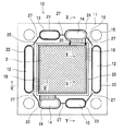
図1Aは本発明の高分子電解質型燃料電用単電池に用いられる膜電極接合体のカソード側の正面図、図1Bは図1Aの膜電極接合体のアノード側の正面図を示す。図2は、図1AのII-II線断面における膜電極接合体の部分拡大断面図である。 1A is a front view of the cathode side of the membrane electrode assembly used in the polymer electrolyte fuel cell unit of the present invention, and FIG. 1B is a front view of the anode side of the membrane electrode assembly of FIG. 1A. FIG. 2 is a partially enlarged cross-sectional view of the membrane electrode assembly taken along the line II-II in FIG. 1A.
高分子電解質型燃料電(PEFC)は、複数の単電池を積層させて構成されたセルスタックを有する。なお、単電池は両端から、ボルト孔15を挿通される締結ボルトとナット(ともに図示なし)とで締結されて構成されている。本実施形態のPEFCでは、単電池10は50個積層されて、ボルト孔15に挿通されるボルトとナットとが締結力10kNで締結されている。
A polymer electrolyte fuel cell (PEFC) has a cell stack formed by stacking a plurality of single cells. The unit cell is configured to be fastened by fastening bolts and nuts (both not shown) inserted through the
単電池100は、膜電極接合体10の両面周縁部の枠体11、より正確には、ガスケットを一対の導電性のセパレータ、具体的にはカソードセパレータ30及びアノードセパレータ40で挟んで構成されている。
The unit cell 100 is constructed by sandwiching a gasket between a pair of conductive separators, specifically, a
膜電極接合体10は、高分子電解質膜1と高分子電解質膜1の一方の面に接合されたカソード側電極層3と高分子電解質膜1の他方の面に接合されたアノード側電極層4とで構成された膜電極接合体本体部2と、膜電極接合体本体部2の周縁部分を挟み、膜電極接合体本体部2の周囲に配置された枠体11とを備える。
The
膜電極接合体本体部2の電極層3,4がセパレータ30,40の表面と当接する。カソードセパレータ30の酸化剤ガス流路溝33とカソード側電極層3で、燃料ガス流路が画定される。一方、アノードセパレータ40の燃料ガス流路溝43とアノード側電極層4で燃料ガス流路が画定される。これにより、燃料ガス流路を流通する燃料ガスはアノードセパレータ40側の電極層4に接触してPEFCの電気化学反応を生じさせる。また、積層された単電池においては、隣接した膜電極接合体本体部2が互いに電気的に直列、または並列に接続される。
The
枠体11は例えば、WO 02/061869などに示されているように、高分子電解質膜1の周縁部に熱可塑性樹脂を射出成形することによって、膜電極接合体本体部2と一体的に結合されている。
For example, as shown in WO 02/061869, the
枠体11を構成する熱可塑性樹脂は、PEFCの運転温度以下において、化学的に清浄かつ安定であって、適度の弾性率と比較的高い加重たわみ温度を有する。具体的には枠体11は化学的安定性の観点から、非晶性樹脂ではなく結晶性樹脂で構成されることが好ましく、その中でも機械的強度が大きくかつ耐熱性の高い材料が好ましい。例えば、いわゆるスーパーエンジニアリングプラスチックグレードのものが好適であり、ポリフェニレンサルファイド(PPS)、ポリエーテルエーテルケトン(PEEK)、結晶ポリマー(LCP)ポリエーテルニトリル(PEN)などが例示できる。これらは、数千から数万MPaの圧縮弾性率と、150℃以上の撓み荷重温度を有しており好適な材料である。また、汎用されている樹脂材料であっても、例えば、ガラスフィラーが充填されたポリプロピレン(GFPP)などは、非充填のポリプロピレン(圧縮弾性率1000〜1500MPa)の数倍の弾性率を有し、かつ150℃近い撓み荷重温度を有しており、好適に使用できる。本実施の形態においては、熱可塑性樹脂であるガラスフィラー添加ポリプロピレン(出光石油化学株式会社R250G)が用いられている。
The thermoplastic resin constituting the
枠体11のカソード側の表面には、燃料ガス及び酸化剤ガス及び冷却水が流通するそれぞれ一対の貫通孔、すなわち、各一対の酸化剤ガスマニフォルド孔12,燃料ガスマニフォルド孔13及び冷却水マニフォルド孔14が設けられている。単電池が積層された状態では、これらの貫通孔が積層して、燃料ガスマニフォルド及び酸化剤マニフォルド及び水マニフォルドを形成する。さらに枠体11には締結用ボルトを通す4個のボルト孔15が設けられている。
On the surface of the
枠体11には、カソードが位置する側の表面に酸化剤ガスマニフォルド孔12及び燃料ガスマニフォルド孔13を囲むガスケット22,23が設けられている。また、水マニフォルド孔14を部分的に囲むガスケット24が設けられている。ガスケット24は、単電池10の組立状態において、カソードセパレータ30の背面側に位置する冷却水流路溝34(図3C参照)の連絡部34Aが当接する位置には配設されないようになっている。ガスケット22,23,24は、ガスケット27によって相互に連結されており、電極層3側との密閉がされるようになっている。
The
枠体11のカソード側表面には、その内縁部に一段低いくぼみ部28を有し、当該段部にガスケット25が設けられている。ガスケット24は、くぼみ部28上に突出する傾斜部16上においてつながっている。当該くぼみ部28には、カソードセパレータ30が嵌入する。
On the cathode side surface of the
酸化剤ガスマニフォルド孔12とくぼみ部28との間は、枠体11内部をその面方向に延在する酸化剤ガス供給用連絡通路18によって連通されている。本実施形態において、酸化剤ガス供給用連絡通路18は複数本設けられている。酸化剤ガス供給用連絡通路18は、酸化剤ガスマニフォルド12とくぼみ部28とを連通するものであり、カソードセパレータ30と電極層3とによって画定された酸化剤ガス流路に酸化剤ガスを供給する。すなわち、酸化剤ガスマニフォルド孔12を流動する酸化剤ガスは、その一部が酸化剤ガス供給用連絡通路18を通って酸化剤ガス流路に流れ込む。また、酸化剤ガス流路を通った酸化剤ガスは、他方の酸化剤マニフォルド孔12側の酸化剤ガス供給用連絡通路18を通って、他方の酸化剤マニフォルド孔12に流入する。この構成については、詳細は後述する。
The oxidant
枠体11のアノード側表面には、内周部に一段高い突部17を有し、その内側の内縁部に一段低い段差29が設けられている。段差29上には、ガスケット26が設けられている。当該段差29には、アノードセパレータ40が嵌入する。
On the anode side surface of the
また、燃料ガスマニフォルド孔13とくぼみ部29との間は、枠体11内部をその面方向に延在する燃料ガス供給用連絡通路19によって連通されている。本実施形態において、燃料ガス供給用連絡通路19は複数本設けられている。燃料ガス供給用連絡通路19は、燃料ガスマニフォルド13とくぼみ部29とを連通するものであり、アノードセパレータ40と電極層4とによって画定された燃料ガス流路に燃料ガスを供給する。すなわち、燃料ガスマニフォルド孔13を流動する燃料ガスは、その一部が燃料ガス供給用連絡通路19を通って燃料ガス流路に流れ込む。また、燃料ガス流路を通った燃料ガスは、他方の燃料マニフォルド孔13側の燃料ガス供給用連絡通路19を通って、他方の燃料ガスマニフォルド孔13に流入する。この構成については、詳細は後述する。
Further, the fuel
なお、上記各ガスケット22,23,24,25,26,27は、熱可塑性樹脂または熱可塑性エラストマーから構成される。この熱可塑性樹脂または熱可塑性エラストマーは、PEFCの運転条件下において化学的に安定で、特に加水分解をおこさないなど耐熱水性を有する。例えば、ガスケットの圧縮弾性率は200MPa以下であることが好ましい。好適な材料は、ポリエチレン、ポリプロピレン、ポリブチレン、ポリスチレン、ポリ塩化ビニル、ポリ塩化ビニリデン、ポリビニルアルコール、ポリアクリルアミド、ポリアミド、ポリカーボネート、ポリアセタール、ポリウレタン、シリコーン、フッ素樹脂、ポリブチレンテレフタレート、ポリエチレンテレフタレート、シンジオタクチック・ポリスチレン、ポリフェニレンサルファイド、ポリエーテルエーテルケトン、ポリスルホン、ポリエーテルサルホン、ポリアリレート、ポリアミドイミド、ポリエーテルイミド、及び熱可塑性ポリイミドなどからなる群より選ばれる。これによって、PEFCの締結荷重において良好なシール性を確保することができる。本実施形態においては、ポリオレフィン系熱可塑性エラストマーであるサントプレン8101−55(Advanced Elasotomer System社製)を用いている。
Each
図3Aにカソードセパレータの正面図を示す。図3Bにカソードセパレータの背面図を示す。図3Cに図3Aの3C−3C線断面におけるカソードセパレータの部分拡大断面図を示す。
FIG. 3A shows a front view of the cathode separator. FIG. 3B shows a rear view of the cathode separator. FIG. 3C is a partial enlarged cross-sectional view of the cathode separator taken along the
カソードセパレータ30は、導電体材料で構成されており、枠体11のくぼみ部28によって形成される段差内に隙間なく嵌入する大きさを有する。本実施形態においては、カソードセパレータは、東海カーボン株式会社製グラッシーカーボン(厚さ3mm)を用いており、124mm角の大きさである。カソードセパレータ30の内側の主面には、くぼみ部28に当接する縁部31が設けられており、当該縁部31の内側に一段高く構成された電極層当接部32が設けられている。電極層当接部32には、酸化剤ガス流路溝33が5本並行して設けられている。酸化剤ガス流路溝33は、一対の酸化剤ガスマニフォルド孔12間を結ぶようにして形成されており当該酸化剤ガス流路溝33の端部33Aは、酸化剤ガス供給用連絡通路18のごく近傍部分に位置し、電極層当接部32の縁まで延在している。
The
カソードセパレータ30の背面側には、並行する5本の溝で構成された冷却水流路溝34が設けられている。冷却水流路溝34の端部34Aは、水マニフォルド孔14の冷却水連通溝20に対応するように設けられており、当該冷却水連通溝20を通ってカソードセパレータ30の背面側に流動した冷却水を当該冷却水流路溝34に送り込むことができるようになっている。なお、後述するように、カソードセパレータ30は、隣接する単電池のアノードセパレータ40の背面と面接触するため、冷却水流路溝34と隣接する単電池のアノードセパレータ40の背面によって画定される流路が冷却水流路として形成される。また、当該冷却水はくぼみ部28に設けられたガスケット25、26によって、電極層3,4側への浸水が防止される。
On the back side of the
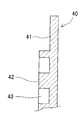
図4Aにアノードセパレータの正面図を示す。図4Bに図4Aの4B−4B線断面におけるアノードセパレータの部分拡大断面図を示す。
FIG. 4A shows a front view of the anode separator. FIG. 4B shows a partially enlarged cross-sectional view of the anode separator taken along the
アノードセパレータ40は、導電体材料で構成されており、枠体11のくぼみ部29によって形成される段差内に隙間なく嵌入する大きさを有する。本実施形態においては、アノードセパレータは、東海カーボン株式会社製グラッシーカーボン(厚さ3mm)を用いており、124mm角の大きさである。アノードセパレータ40の内側の主面には、くぼみ部29に当接する縁部41が設けられており、当該縁部41の内側に一段高く構成された電極層当接部42が設けられている。電極層当接部42には、燃料ガス流路溝43が3本並行して設けられている。燃料ガス流路溝43は、一対の燃料ガスマニフォルド孔13間を結ぶようにして形成されており、当該燃料ガス流路溝43の端部43Aは、燃料ガス供給用連絡通路19のごく近傍部分に位置し、電極層当接部42の縁まで延在している。
The
アノードセパレータ40及びカソードセパレータ30の背面には、耐熱性の材料からなるスクイーズドパッキンなどの一般的なシール部材を配設してもよい。これによって、隣接する単電池の間において、水マニフォルド孔14の単電池10間の連接部からの燃料ガス、酸化剤ガス及び水の流出が防止される。
A general sealing member such as a squeezed packing made of a heat-resistant material may be disposed on the back surface of the
上記構成の膜電極接合体10、カソードセパレータ30及びアノードセパレータ40を組み合わせて構成される単電池の構成を図5及び図6に示す。図5は、アノードセパレータとカソードセパレータを配設した状態にある図1の膜電極接合体のV-V線断面における部分拡大断面図であり、アノードセパレータとカソードセパレータを配設した状態にある図1の膜電極接合体のVI-VI線断面における部分拡大断面図である。
FIGS. 5 and 6 show the configuration of a unit cell configured by combining the
膜電極接合体10、アノード側及びカソード側の中央部に組み合わせたカソードセパレータ30及びアノードセパレータ40により、単電池が構成される。そして、単電池を複数枚積層したセルスタックを締結する締結圧により、各ガスケット22,23,24,27は、隣合う単電池の枠体同士が面接触して積層方向に圧縮され、それぞれのマニフォルドと外部とを気密に遮蔽する。また、単電池の組立時において、セパレータは隣り合う単電池のセパレータと面接触するため、ガスケット25,26は、枠体11とセパレータの縁部31,41によって積層方向に圧縮されて電極部分を密閉し、燃料ガス及び酸化剤ガスが外部に漏れ出すのを防止する。
A unit cell is constituted by the
組立時においては、一方のマニフォルド、すなわち供給側のマニフォルド12,13から、酸化剤ガス供給用連絡通路18及び燃料ガス供給用連絡通路19に分岐して、流路溝33,43に流入する。そして、セパレータと電極層で画定された燃料ガス及び酸化剤ガスのそれぞれの流路を通って、他方の酸化剤ガス供給用連絡通路18及び燃料ガス供給用連絡通路19を通って、他方のマニフォルド、すなわち、排出側のマニフォルドに排出される。
At the time of assembly, the manifold branches from one manifold, that is, the supply-
また、隣接する単電池のカソードセパレータ30とアノードセパレータ40との間には、冷却水の流路が形成される。膜電極接合体10の入り口側マニフォルド14から供給される冷却水は冷却水の一方の冷却水連通溝20を通ってカソードセパレータ30の冷却水流路用溝34に入り、他方の冷却水連通溝20を通って出口側のマニフォルド孔14に排出される。冷却水連通溝20は5本の溝で構成されている。このように流れる冷却水はマニフォルド孔14から冷却水連通溝20にわたる部分では、膜電極接合体のガスケット24が隣接する膜電極接合体との間で圧縮されて外部への漏出が防止される。膜電極接合体10のくぼみ部28の上側ではガスケット22,23,24,27が隣り合う膜電極接合体の枠体との間で圧縮され外部への流出が防止され、くぼみ部ではガスケット25,26によって電極層への浸入が防止されるため、電極層に冷却水が接触することはない。
In addition, a cooling water flow path is formed between the
本実施形態においては、セパレータ30,40は、電極部全面を被覆するような大きさで、膜電極接合体10の枠体11の中央に組み合わされる。また、電極層への燃料ガス及び酸化剤ガスは、枠体の内部を通過するため、セパレータは電極層を被覆できる大きさであれば十分である。したがって、カーボン材の使用量を大幅に削減することができる。
In the present embodiment, the
上記構成の枠体11は、例えば、射出成形などの手段により製造することができる。そして、枠体11内部をその面方向に延在する酸化剤ガス供給用連絡通路18及び燃料ガス供給用連絡通路19は、射出成形用の金型内に配置されるコアなどを用いることによって、成形される。
The
図7A〜図7Dは、枠体を製造するための射出成形用金型及びその製造工程を説明するための図である。 7A to 7D are views for explaining an injection mold for manufacturing a frame body and a manufacturing process thereof.
まず、図7Aに示す第1工程において、枠体11の所定位置に酸化剤ガス供給用連絡通路18及び燃料ガス供給用連絡通路19を形成するためのコアT5が移動する。コアT5は、エジェクタープレートT3に図示左右方向に移動可能に支持されている。コアT5は、外側の面T5Aが傾斜するように構成されており、矢印90に示すようにエジェクタープレートT3の下方向への移動に伴い矢印91に示すように斜めに移動する。
First, in the first step shown in FIG. 7A, the core T5 for forming the oxidant gas
ここで、第1金型T1は、枠体部T1Aが枠体11のマニフォルド孔を形成するような形状に対応する形状を有するように構成されている。コアT5は、内側面に通路形成用ピンT5Bが設けられており、第1金型T1のコア収納部T1Bに収納されたとき、枠体部T1Aに酸化剤ガス供給用連絡通路18及び燃料ガス供給用連絡通路19を形成させる位置に配置されるように構成されている。
Here, the first mold T1 is configured to have a shape corresponding to a shape in which the frame portion T1A forms a manifold hole of the
また、第1金型T1の枠内部分には、膜電極接合体本体部2を配置できるような平坦部T1Cが構成されている。図7Bは平坦部T1Cに膜電極接合体本体部2を配置した状態を示している。平坦部T1Cは、枠体部T1Aの枠内縁側から、枠体11の枠面と略平行に伸びる頂面を有する。さらに、膜電極接合体本体部2を平面上に収容して配置したとき、膜電極接合体本体部2の周縁が第1金型T1の枠内部T1Aの部分に位置するように構成されている。つまり、平坦部T1Cは、その頂面が延伸して構成される第1金型T1の枠内部分において、膜電極接合体本体部2の外縁よりも数ミリ程度小さく構成されている。
In addition, a flat portion T1C in which the membrane electrode assembly
次に、図7Bの矢印92に示すように、第2金型T2と第4金型T4とが図示した方向に移動して第1金型T1に当接され、成形用キャビティが形成される。第2金型T2は、上面にランナーがT2A、第2スプルーT2Bが設けられており、第4金型の射出口T4Aから射出された溶融樹脂を、第1スプルーT4Bを通して成形用キャビティに射出する。
Next, as shown by an
第2金型T2は、突出部T2Cが第1金型T1の平坦部T1Cに載置された膜電極接合体本体部2を挟むように構成されており、樹脂射出時において膜電極接合体本体部2の表面に樹脂が射出されないように構成されている。また、枠体部T1Aに配置されたコアT5の通路形成用ピンT5Bによって、枠体部T1Aに酸化剤ガス供給用連絡通路18及び燃料ガス供給用連絡通路19が形成される。
The second mold T2 is configured such that the projecting portion T2C sandwiches the membrane electrode assembly
図7Cに示すように枠体11の射出成形が終了すると、矢印93に示すように第2金型T2及び第4金型T4を上昇させ、第1金型から取り除く。このとき第1金型T1の枠体部T1Aには、射出成型物としての枠体11が作製されている。
When the injection molding of the
次に図7Dの矢印94に示すようにエジェクタープレートT3を上昇させる。エジェクタープレートT3に支持されているコアT5は、上昇して枠体11を第1金型T1から押し出すと共に、その傾斜面T5Aに沿って矢印95に示すように図示左右方向に広がって、枠体に挿入された状態となっている通路形成用ピンT5Bが抜ける。通路形成用ピンT5Bが抜けた後には、酸化剤ガス供給用連絡通路18及び燃料ガス供給用連絡通路19が形成される。
Next, as shown by an
この後、膜電極接合体本体部3が接合された枠体11に好適な方法によりガスケット7が形成されて膜電極接合体10が製作される。
Thereafter, the gasket 7 is formed on the
(実施例)
図1Aに示す構造を有する膜電極接合体を作成した。高分子電解質膜1は、Dupont社のNaphion117、50μm厚)をトムソン型により140mm角の形状に打ち抜いた。次に、比表面積800m2/g、DBP吸油量360ml/100gのケッチェンブラックEC(ケッチェンブラック・インターナショナル社製ファーネスブラック)に、白金を重量比1:1の割合で担持させた。この触媒粉末10gに、水35gおよび水素イオン伝導性高分子電解質のアルコール分散液(旭硝子(株)製、9%FSS)59gを混合し、超音波攪拌機を用いて分散させて、触媒層インクを作製した。この触媒インクを、ポリプロピレンフィルム(東レ(株)製トレファン50−2500)に塗工し、乾燥して触媒層を形成した。得られた触媒層を120mm×120mmに切断し、高分子電解質膜のアノード側およびカソード側両面に、温度135℃、圧力32kgf/cm2の条件で転写し、触媒層電極を形成した。触媒層電極形成後触媒層の表面に、123mm角のガス拡散電極を(ジャパンゴアテックス製 カーベルCF400 厚み400ミクロン)嵌めこんだ後、圧力20kgf/cm2の条件で圧接して電極層を作成し、膜電極接合体本体部4を製作した。
(Example)
A membrane electrode assembly having the structure shown in FIG. 1A was prepared. The polymer electrolyte membrane 1 was a Dupont Naphion 117 (50 μm thick) punched into a 140 mm square shape using a Thomson mold. Next, platinum was supported in a ratio of 1: 1 by weight on Ketjen Black EC (furnace black manufactured by Ketjen Black International Co., Ltd.) having a specific surface area of 800 m 2 / g and DBP oil absorption of 360 ml / 100 g. To 10 g of this catalyst powder, 35 g of water and 59 g of an alcohol dispersion of hydrogen ion conductive polymer electrolyte (9% FSS, manufactured by Asahi Glass Co., Ltd.) are mixed and dispersed using an ultrasonic stirrer. Produced. This catalyst ink was applied to a polypropylene film (Treffan 50-2500 manufactured by Toray Industries, Inc.) and dried to form a catalyst layer. The obtained catalyst layer was cut into 120 mm × 120 mm, and transferred to both the anode side and the cathode side of the polymer electrolyte membrane under the conditions of a temperature of 135 ° C. and a pressure of 32 kgf / cm 2 to form a catalyst layer electrode. After the catalyst layer electrode is formed, a 123mm square gas diffusion electrode (Carvel CF400, 400 microns in thickness by Japan Gore-Tex) is fitted on the surface of the catalyst layer, and then pressed to create an electrode layer under a pressure of 20 kgf / cm 2. A membrane
この膜電極接合体本体部2をインサート部品として、グラスファイバー添加ポリプロピレン(出光石油化学株式会社 R250G)を用いての枠体11を形成し、膜電極接合体を得た。
Using this membrane electrode assembly
枠体11は、各一対の酸化剤ガスマニフォルド孔12、燃料ガスマニフォルド孔13、水マニフォルド孔14が設けられ、また単電池を締結するボルトを貫通させるための複数個のボルト孔15を設けた。さらに、カソードが位置する側の表面に、酸化剤ガスマニフォルド孔12、燃料ガスマニフォルド孔13、水マニフォルド孔14を囲むガスケット22,23,24を設けた。
The
また、アノード側およびカソード側の両面において、電極部分の外周と枠体部分の内周にくぼみ部をつけ、低いほうの段差部にセパレータの周縁部31,41と当接する方向にガスケット26,26を設けた。また、マニフォルド孔12,13から電極部分に燃料ガス及び酸化剤ガスを供給するための流路として酸化剤ガス供給用連絡通路18及び燃料ガス供給用連絡通路19を枠体11に沿って延在して配置した。
Further, on both the anode side and the cathode side, recesses are formed in the outer periphery of the electrode portion and the inner periphery of the frame portion, and the
セパレータは東海カーボン株式会社製グラッシーカーボン(t=3mm)を材料として用いた。セパレータはアノード用とカソード用の2種を製作し、各々の表面に上記の各種溝を切削機械加工で製作した。 As a separator, glassy carbon (t = 3 mm) manufactured by Tokai Carbon Co., Ltd. was used as a material. Two types of separators for anode and cathode were manufactured, and the above-mentioned various grooves were manufactured on each surface by cutting machining.
以上のように製作した膜電極接合体10とアノードセパレータ40とカソードセパレータ30を用いて、膜電極接合体10をアノードセパレータ40とカソードセパレータ30で両側から挟み込むことにより、単位電池を製作した。
A unit cell was manufactured by sandwiching the
このような単位電池を50個積層し、両端部には金属製の集電板と電気絶縁材料の絶縁板、さらに端板と締結ロッドで固定し、水素と空気を通じ、冷却水を循環して電池試験を行った。水素利用率70%、酸素利用率20%、水素加湿バブラー温度85℃、酸素加湿バブラー温度75℃、電池温度75℃の条件での電池出力は、1050W(30A−35V)であった。 50 such unit cells are stacked, fixed at both ends with a metal current collector plate and an insulating plate made of an electrically insulating material, and further fixed with an end plate and a fastening rod, and circulating cooling water through hydrogen and air. A battery test was conducted. The battery output under the conditions of a hydrogen utilization rate of 70%, an oxygen utilization rate of 20%, a hydrogen humidification bubbler temperature of 85 ° C., an oxygen humidification bubbler temperature of 75 ° C., and a battery temperature of 75 ° C. was 1050 W (30 A-35 V).
以上説明したように、低いコストで、高いガスシール性をもつ高分子電解質型燃料電池用単電池を製作することが可能であり、もって燃料電池の信頼性向上に寄与することができる。 As described above, it is possible to manufacture a unit cell for a polymer electrolyte fuel cell having a high gas sealing property at a low cost, thereby contributing to an improvement in the reliability of the fuel cell.
なお、本発明は上記実施形態に限定されるものではなく、その他種々の態様で実施可能である。 In addition, this invention is not limited to the said embodiment, It can implement in another various aspect.
本発明によれば、低いコストで、高いガスシール性をもつ燃料電池を製作することが可能である。この燃料電池はコージェネレーションシステムや電気自動車などに有用である。 According to the present invention, it is possible to manufacture a fuel cell having high gas sealing performance at low cost. This fuel cell is useful for cogeneration systems and electric vehicles.
1 高分子電解質膜
2 膜電極接合体本体部
3 アノード側電極層
4 カソード側電極層
10 膜電極接合体
11 枠体
12 酸化剤マニフォルド孔
13 燃料ガスマニフォルド孔
14 水マニフォルド孔
15 ボルト孔
16 傾斜部
17 突部
18 酸化剤ガス供給用連絡通路
19 燃料ガス供給用連絡通路
22,23,24,25,26,27 ガスケット
28,29 くぼみ部
30 カソードセパレータ
31 縁部
32 電極層当接部
33 酸化剤ガス流路溝
34 冷却水流路溝
40 アノードセパレータ
41 縁部
42 電極層当接部
43 燃料ガス流路溝
DESCRIPTION OF SYMBOLS 1
Claims (2)
前記膜電極接合体本体部の電極層を被覆すると共に前記膜電極接合体本体部の両面を挟み、前記電極層と接触して流体流路を画定する流路形成溝を備えるアノードセパレータ及びカソードセパレータと、枠体内部をその面方向に延在し、マニフォルド孔と流体流路とを連通するガス供給用連絡通路を備え、
前記枠体は、内周縁にくぼみ部が設けられ、前記くぼみ部の周囲に酸化剤ガス及び燃料ガスそれぞれについて各一対のマニフォルド孔を備えると共に、
前記枠体の前記くぼみ部内にセパレータ用ガスケットを設け、前記マニフォルド孔の周囲に前記マニフォルド孔用のガス用ガスケットを設け、前記ガス用ガスケット及び前記セパレータ用ガスケットが変形して、前記マニフォルド孔及び前記流体流路を外部と気密に隔離することを特徴とする高分子電解質型燃料電池用単電池。 A membrane / electrode assembly main body comprising a polymer electrolyte membrane and electrode layers respectively provided on both surfaces of the electrolyte membrane; and a peripheral edge of the membrane / electrode assembly main body and sandwiching the outer edge of the polymer electrolyte membrane A membrane electrode assembly comprising a plate-like frame body formed so as to surround;
An anode separator and a cathode separator that have a channel forming groove that covers an electrode layer of the membrane electrode assembly main body and sandwiches both surfaces of the membrane electrode assembly main body and defines a fluid channel in contact with the electrode layer And a gas supply communication passage that extends inside the frame in the surface direction and communicates the manifold hole and the fluid flow path,
The frame body, the recess portion is provided on the inner periphery, Rutotomoni with each pair of manifold holes for each oxidant gas and the fuel gas to the periphery of said well,
A separator gasket is provided in the indented portion of the frame body , a gas gasket for the manifold hole is provided around the manifold hole, the gas gasket and the separator gasket are deformed, and the manifold hole and the polymer electrolyte fuel unit cell battery, which comprises isolating the fluid flow path to the outside and hermetically.
Priority Applications (1)
| Application Number | Priority Date | Filing Date | Title |
|---|---|---|---|
| JP2006181287A JP5068484B2 (en) | 2006-06-30 | 2006-06-30 | Single cell for polymer electrolyte fuel cell and polymer electrolyte fuel cell |
Applications Claiming Priority (1)
| Application Number | Priority Date | Filing Date | Title |
|---|---|---|---|
| JP2006181287A JP5068484B2 (en) | 2006-06-30 | 2006-06-30 | Single cell for polymer electrolyte fuel cell and polymer electrolyte fuel cell |
Publications (3)
| Publication Number | Publication Date |
|---|---|
| JP2008010350A JP2008010350A (en) | 2008-01-17 |
| JP2008010350A5 JP2008010350A5 (en) | 2008-10-02 |
| JP5068484B2 true JP5068484B2 (en) | 2012-11-07 |
Family
ID=39068356
Family Applications (1)
| Application Number | Title | Priority Date | Filing Date |
|---|---|---|---|
| JP2006181287A Active JP5068484B2 (en) | 2006-06-30 | 2006-06-30 | Single cell for polymer electrolyte fuel cell and polymer electrolyte fuel cell |
Country Status (1)
| Country | Link |
|---|---|
| JP (1) | JP5068484B2 (en) |
Families Citing this family (7)
| Publication number | Priority date | Publication date | Assignee | Title |
|---|---|---|---|---|
| KR100917732B1 (en) | 2007-03-30 | 2009-09-15 | 파나소닉 주식회사 | Polymer electrolyte fuel cell and electrode/film/frame assembly manufacturing method |
| EP2058883B1 (en) | 2007-03-30 | 2013-03-13 | Panasonic Corporation | Polymer electrolyte fuel cell and electrode/film/frame assembly manufacturing method |
| JP5365162B2 (en) * | 2008-11-26 | 2013-12-11 | 日産自動車株式会社 | Fuel cell |
| JP5896556B2 (en) * | 2012-02-29 | 2016-03-30 | 興国インテック株式会社 | Manufacturing method of plate with seal and cavity plate |
| JP6218065B2 (en) * | 2013-06-13 | 2017-10-25 | パナソニックIpマネジメント株式会社 | Fuel cell separator and method for producing the same |
| JP6368807B2 (en) * | 2016-02-02 | 2018-08-01 | 本田技研工業株式会社 | Manufacturing method of fuel cell stack and manufacturing method of metal separator for fuel cell |
| US10305135B2 (en) | 2016-02-02 | 2019-05-28 | Honda Motor Co., Ltd. | Method of producing fuel cell stack and method of producing metal separator for fuel cell |
Family Cites Families (12)
| Publication number | Priority date | Publication date | Assignee | Title |
|---|---|---|---|---|
| JP3489181B2 (en) * | 1994-03-10 | 2004-01-19 | トヨタ自動車株式会社 | Unit cell of fuel cell and method of manufacturing the same |
| JP3594345B2 (en) * | 1994-12-06 | 2004-11-24 | 株式会社エクォス・リサーチ | Fuel cell separator |
| JP3594347B2 (en) * | 1994-12-26 | 2004-11-24 | 株式会社エクォス・リサーチ | Fuel cell stack |
| JP3424223B2 (en) * | 1995-03-29 | 2003-07-07 | マツダ株式会社 | Fuel cell stack structure |
| JP2001176520A (en) * | 1999-12-16 | 2001-06-29 | Araco Corp | Fuel cell and separator for fuel cell |
| JP3785909B2 (en) * | 2000-08-24 | 2006-06-14 | トヨタ自動車株式会社 | Manufacturing method of fuel cell separator |
| US6840969B2 (en) * | 2001-01-31 | 2005-01-11 | Matsushita Electric Industrial Co., Ltd. | High polymer electrolyte fuel cell and electrolyte film-gasket assembly for the fuel cell |
| JP2003077495A (en) * | 2001-08-30 | 2003-03-14 | Sanyo Electric Co Ltd | Fuel cell |
| JP4439966B2 (en) * | 2003-04-02 | 2010-03-24 | パナソニック株式会社 | Fuel cell electrolyte membrane structure, fuel cell electrolyte membrane-electrode assembly structure, and fuel cell |
| JP4546167B2 (en) * | 2004-06-28 | 2010-09-15 | パナソニック株式会社 | Polymer electrolyte fuel cell |
| JP4676191B2 (en) * | 2004-11-30 | 2011-04-27 | クレハエラストマー株式会社 | Fuel cell separator |
| JP5143336B2 (en) * | 2004-12-13 | 2013-02-13 | パナソニック株式会社 | Polymer electrolyte fuel cell |
-
2006
- 2006-06-30 JP JP2006181287A patent/JP5068484B2/en active Active
Also Published As
| Publication number | Publication date |
|---|---|
| JP2008010350A (en) | 2008-01-17 |
Similar Documents
| Publication | Publication Date | Title |
|---|---|---|
| JP4099519B2 (en) | Membrane electrode assembly for fuel cell, polymer electrolyte fuel cell, polymer electrolyte fuel cell and method for producing membrane electrode assembly | |
| JP4719771B2 (en) | Electrode-membrane-frame assembly for fuel cell and manufacturing method thereof, and polymer electrolyte fuel cell and manufacturing method thereof | |
| JP3897808B2 (en) | MEA, MEA manufacturing method, and polymer electrolyte fuel cell | |
| JP4904439B2 (en) | Polymer fuel cell stack | |
| JP5068484B2 (en) | Single cell for polymer electrolyte fuel cell and polymer electrolyte fuel cell | |
| US11038190B2 (en) | Membrane electrode assembly, fuel cell comprising assembly of this type and motor vehicle comprising said fuel cell | |
| EP2523244B1 (en) | Electrode-membrane-frame assembly, method for producing same, and fuel cell | |
| US20110053030A1 (en) | Fuel Cell with Gas Diffusion Layer having Flow Channel and Manufacturing Method Thereof | |
| JPWO2009072291A1 (en) | Method for producing electrode-membrane-frame assembly | |
| US8999592B2 (en) | Fuel cell | |
| JP2003197224A (en) | High polymer electrolyte fuel cell | |
| JP2008171613A (en) | Fuel cells | |
| EP2942830B1 (en) | Solid polymer electrolyte fuel cell | |
| US20090311566A1 (en) | Separating plate for fuel cell stack and method of manufacturing the same | |
| US20210098799A1 (en) | Fuel-cell unit cell | |
| JP5143336B2 (en) | Polymer electrolyte fuel cell | |
| JP2004139788A (en) | Composite separator laminae for polymer electrolyte fuel cells and polymer electrolyte fuel cell using it | |
| JP2015170398A (en) | Solid-state polymer electrolytic fuel battery | |
| JP2009117260A (en) | Mea member, and polymer electrolyte fuel cell equipped with the same | |
| KR102425934B1 (en) | Fuel cell stack | |
| JP4611653B2 (en) | Fuel cell separator and method for producing the same | |
| KR101937134B1 (en) | Gasket embedded separator for fuel cell | |
| JP2022048654A (en) | Manufacturing method of fuel battery cell | |
| JP6021683B2 (en) | Fuel cell and assembly method thereof | |
| CN115425250A (en) | Fuel cell |
Legal Events
| Date | Code | Title | Description |
|---|---|---|---|
| A521 | Written amendment |
Free format text: JAPANESE INTERMEDIATE CODE: A523 Effective date: 20080820 |
|
| A621 | Written request for application examination |
Free format text: JAPANESE INTERMEDIATE CODE: A621 Effective date: 20080820 |
|
| RD04 | Notification of resignation of power of attorney |
Free format text: JAPANESE INTERMEDIATE CODE: A7424 Effective date: 20081003 |
|
| A977 | Report on retrieval |
Free format text: JAPANESE INTERMEDIATE CODE: A971007 Effective date: 20110912 |
|
| A131 | Notification of reasons for refusal |
Free format text: JAPANESE INTERMEDIATE CODE: A131 Effective date: 20110920 |
|
| A521 | Written amendment |
Free format text: JAPANESE INTERMEDIATE CODE: A523 Effective date: 20111117 |
|
| TRDD | Decision of grant or rejection written | ||
| A01 | Written decision to grant a patent or to grant a registration (utility model) |
Free format text: JAPANESE INTERMEDIATE CODE: A01 Effective date: 20120807 |
|
| A01 | Written decision to grant a patent or to grant a registration (utility model) |
Free format text: JAPANESE INTERMEDIATE CODE: A01 |
|
| A61 | First payment of annual fees (during grant procedure) |
Free format text: JAPANESE INTERMEDIATE CODE: A61 Effective date: 20120815 |
|
| FPAY | Renewal fee payment (event date is renewal date of database) |
Free format text: PAYMENT UNTIL: 20150824 Year of fee payment: 3 |
|
| R150 | Certificate of patent or registration of utility model |
Ref document number: 5068484 Country of ref document: JP Free format text: JAPANESE INTERMEDIATE CODE: R150 Free format text: JAPANESE INTERMEDIATE CODE: R150 |