EP1510972A2 - 3D image processing apparatus - Google Patents
3D image processing apparatus Download PDFInfo
- Publication number
- EP1510972A2 EP1510972A2 EP04253316A EP04253316A EP1510972A2 EP 1510972 A2 EP1510972 A2 EP 1510972A2 EP 04253316 A EP04253316 A EP 04253316A EP 04253316 A EP04253316 A EP 04253316A EP 1510972 A2 EP1510972 A2 EP 1510972A2
- Authority
- EP
- European Patent Office
- Prior art keywords
- image
- data
- unit
- volume data
- images
- Prior art date
- Legal status (The legal status is an assumption and is not a legal conclusion. Google has not performed a legal analysis and makes no representation as to the accuracy of the status listed.)
- Granted
Links
Images




Classifications
-
- G—PHYSICS
- G06—COMPUTING OR CALCULATING; COUNTING
- G06T—IMAGE DATA PROCESSING OR GENERATION, IN GENERAL
- G06T12/00—Tomographic reconstruction from projections
- G06T12/10—Image preprocessing, e.g. calibration, positioning of sources or scatter correction
-
- A—HUMAN NECESSITIES
- A61—MEDICAL OR VETERINARY SCIENCE; HYGIENE
- A61B—DIAGNOSIS; SURGERY; IDENTIFICATION
- A61B6/00—Apparatus or devices for radiation diagnosis; Apparatus or devices for radiation diagnosis combined with radiation therapy equipment
- A61B6/48—Diagnostic techniques
- A61B6/481—Diagnostic techniques involving the use of contrast agents
-
- A—HUMAN NECESSITIES
- A61—MEDICAL OR VETERINARY SCIENCE; HYGIENE
- A61B—DIAGNOSIS; SURGERY; IDENTIFICATION
- A61B6/00—Apparatus or devices for radiation diagnosis; Apparatus or devices for radiation diagnosis combined with radiation therapy equipment
- A61B6/50—Apparatus or devices for radiation diagnosis; Apparatus or devices for radiation diagnosis combined with radiation therapy equipment specially adapted for specific body parts; specially adapted for specific clinical applications
- A61B6/504—Apparatus or devices for radiation diagnosis; Apparatus or devices for radiation diagnosis combined with radiation therapy equipment specially adapted for specific body parts; specially adapted for specific clinical applications for diagnosis of blood vessels, e.g. by angiography
-
- A—HUMAN NECESSITIES
- A61—MEDICAL OR VETERINARY SCIENCE; HYGIENE
- A61B—DIAGNOSIS; SURGERY; IDENTIFICATION
- A61B6/00—Apparatus or devices for radiation diagnosis; Apparatus or devices for radiation diagnosis combined with radiation therapy equipment
- A61B6/58—Testing, adjusting or calibrating thereof
- A61B6/582—Calibration
- A61B6/583—Calibration using calibration phantoms
- A61B6/584—Calibration using calibration phantoms determining position of components of the apparatus or device using images of the phantom
-
- G—PHYSICS
- G06—COMPUTING OR CALCULATING; COUNTING
- G06T—IMAGE DATA PROCESSING OR GENERATION, IN GENERAL
- G06T2211/00—Image generation
- G06T2211/40—Computed tomography
- G06T2211/404—Angiography
Definitions
- the present invention relates to a 3D image processing apparatus.
- a highly precise blood vessel structure can be extracted from a 3D-DSA image reconstructed from a plurality of DSA (Digital Subtraction Angiography) images corresponding to a plurality of projection directions.
- 3D-DSA images therefore are very useful for IVR support.
- the data of bones and soft tissues, other than contrasted blood vessels, are removed.
- 3D-DSA images therefore include no bone structure.
- the 3D-DSA images are low in utility for surgical operation support.
- a 3D-DA image reconstructed from a plurality of DA (Digital Angiography) images corresponding to a plurality of projection directions includes a bone structure and blood vessel structure. An observer can therefore grasp the position of the blood vessel relative to the bone from the 3D-DA image.
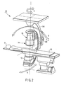
- a 3D X-ray diagnosing apparatus has an X-ray imaging mechanism 10 and 3D image processing apparatus 1.
- the X-ray imaging mechanism 10 has an X-ray tube 12 and detection system 14.
- the detection system 14 is constituted by an image intensifier and TV camera.
- the detection system 14 may be formed from a flat panel detector.
- the X-ray tube 12 is mounted on a C-arm 160 together with the detection system 14.
- An object P to be examined on a top 50 of a bed is placed between the X-ray tube 12 and the detection system 14.
- the C-arm 160 is supported by a support 164 suspended from the ceiling.
- the C-arm 160 can rotate along three orthogonal axes A, B, and C.
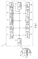
- the 3D image processing apparatus 1 includes a control unit 37 serving as a main component, an A/D converter 21, an input device 22, a storing unit 23, a subtracting unit 31, a distortion correcting unit 32, an affine converter 36, a 3D reconstruction processing unit 33, a 3D image processing unit 35, an image synthesizing unit 34, a D/A converter 38, and a displaying unit 39.
- the A/D converter 21 is connected to the detection system 14.
- the D/A converter 38 is connected to the displaying unit 39.
- the input device 22 has a keyboard and mouse.
- the storing unit 23 stores various data such as image data, volume data, and synthetic image data input through the A/D converter 21.
- the subtracting unit 31 has a function of subtracting image data and a function of subtracting image data or volume data. In the subtracting process of the former, a logarithm natural of two data is computed, and the two data are subtracted after that. In the subtracting process of the latter, a two data are subtracted directly.
- the former is named as the first subtracting process, and the latter is named as the second subtracting process in the following.
- the distortion correcting unit 32 has distortion correction processing for correcting image distortion to originate in the Image Intensifie.
- the affine converter 36 performs enlargement processing and movement processing.
- the 3D reconstruction processing unit 33 reconstructs volume data from a plurality of image data corresponding to a plurality of projection directions.
- the 3D image processing unit 35 generates 3D image data from volume data by surface rendering processing.
- the image synthesizing unit 34 generates synthetic image data by synthesizing two or more kinds of 3D images.
- a contrast media is injected into a blood vessel of the object.
- a plurality of image data corresponding to a plurality of projection directions are acquired.
- Images acquired before injection of the contrast media are called mask images.
- the mask images include an image of a bone and an image of a soft tissue. Pixel values in the respective images reflect transmittances unique to the bone and soft tissue.
- the contrast images include an image of the bone, an image of the soft tissue, and an image of the blood vessel.
- a pixel value in the image of the bone reflects a transmittance unique to the bone.
- a pixel value in the image of the soft tissue reflects a transmittance unique to the soft tissue.
- a pixel value in the image of the blood vessel reflects a transmittance unique to the contrast media in the blood vessel instead of the blood vessel.
- the transmittance of the contrast media is much lower than that of the blood vessel.
- the data of the 200 mask images are stored in the storing unit 23.
- the data of the 200 contrast images are stored in the storing unit 23.
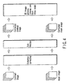
- These mask image data and contrast image data are subjected to distortion correction processing by the distortion correcting unit 32, as shown in FIG. 4.
- distortion correction processing processing using a phantom having wires arranged at equal intervals vertically and horizontally in the form of a square lattice.
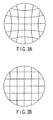
- a projection image of the phantom ideally has a square lattice shape, as shown in FIG. 3B.
- the projection image of the phantom undergoes pincushion distortion due to the shape of the detection surface of the detection system 14 and sigmoid distortion due to geomagnetism, as shown in FIG. 3A.
- the distorted image data shown in FIG. 3A is acquired in advance, and the intersections of the wires are extracted as lattice points from this distorted image data.
- These lattice points should be arranged at equal intervals in the absence of distortion. Therefore, correction vectors for arraying the lattice points at equal intervals are obtained for each lattice point.
- the mask and contrast images are corrected in accordance with the correction vectors. Points other than the lattice points are corrected by using the data of neighboring lattice points. Note that since different distortion distributions appear at different angles, a distortion distribution table measured from acquired angle-specific phantom projection images is held, and distortion is corrected on the basis of the table.
- the subtracting unit 31 corrects density non-uniformlty in a mask image. Likewise, the subtracting unit 31 corrects density non-uniformity in a contrast image.
- the processing for correcting density non-uniformlty subtracts a image for correcting density non-uniformity from a mask or contrast image in the first subtracting process.
- the image for correcting density non-uniformity is obtained by imaging in a state wherein nothing other than air is interposed between the X-ray tube 12 and the detection system 14.
- This embodiment provides three kinds of 3D image processes for separately generating 3D image data representing a bone structure and 3D image data representing a contrasted blood vessel structure.
- the three kinds of 3D image processes are shown in FIGS. 4, 5, and 6.
- a desired one of the three kinds of 3D image processing is selected by an operator through the input device 22.
- An angio-image and bone image are generated by the selected process.
- a synthetic image of the generated angio-image and bone image is displayed.
- volume data (mask) is generated (see FIG. 9B).
- the volume data (mask) includes the 3D structure of the bone, the 3D structure of the soft tissue.
- a plurality of DSA images are subjected to 3D reconstruction processing by the 3D reconstruction processing unit 33.
- volume data (DSA) is generated (see FIG. 9C).
- the volume data (DSA) includes only the 3D structure of the contrasted blood vessel.
- the filtered back projection method proposed by Feldkamp et al. is generally used.
- An appropriate convolution filter such as a Shepp-Logan filter or Ramachandran filter is applied to the 200 DSA images.
- the 200 DSA images processed by the convolution filter are then subjected to back projection operation.
- volume data (DSA) is generated.
- an appropriate convolution filter is applied to the 200 corrected mask images.
- the 200 corrected mask images processed by the convolution filter are then subjected to back projection operation.
- volume data (mask) is generated.
- a reconstruction region is defined as a cylinder inscribed in an X-ray beam from the X-ray tube 12 in all directions.
- the inside of this cylinder is three-dimensionally discretized with a length d at the central portion of the reconstruction region projected by the width of one detection element of the detection system 14, and a reconstructed image based on the data of each discrete point must be obtained.
- the discrete interval may differ depending on the apparatus or maker. Basically, therefore, it suffices if the discrete interval defined for each apparatus be used.
- the volume data (mask) is subjected to surface rendering processing by the 3D image processing unit 35. This generates a 3D image (3D bone image) representing the 3D structure of the bone.
- the volume data (DSA) is subjected to surface rendering processing by the 3D image processing unit 35. This generates a 3D image (3D angio-image) representing the 3D structure of the contrasted blood vessel.
- the surface rendering processing is processing of rearranging volume data into a 2D pixel matrix so as to render the data on the displaying unit 39 having a 2D display screen.
- the image data is arranged as 2D matrix data but expresses the 3D structure of the object. In this case, therefore, this image will be referred to as a 3D image in particular.
- the coordinate position of the volume data is converted to a viewpoint coordinate system.
- the viewpoint coordinate system for the volume data coincides with that for the volume data (DSA).
- occlusion processing and shading processing of shading an object surface are executed with respect to the converted volume data. As a consequence, 3D image data is generated.
- volume rendering processing for the volume data is performed for only voxels having voxel values (CT values) within a range corresponding to the bone. This generates a 3D bone image.
- volume rendering processing for the volume data is performed for only voxels having voxel values (CT values) within a range corresponding to the contrasted blood vessel. This generates a 3D angio-image.
- the image synthesizing unit 34 generates the 3D image (mask) based on the volume data (mask) and generates the 3D image (DSA) originated from the volume data (DSA), by using the hidden plane removal processing.
- the image synthesizing unit 34 synthesizs the 3D image (mask) and the 3D image (DSA). As a consequence, a synthetic image (3D angio/bone image) is generated.
- the 3D image processing of this embodiment is characterized in that the 3D image (3D bone image) representing the 3D structure of the bone and the 3D image (3D angio-image) representing the 3D structure of the contrasted blood vessel are independently generated. Therefore, the 3D structure of the blood vessel can be displayed by the color which is different from the 3D structure of the bone.
- the 3D structure of the blood vessel can be identified from the 3D structure of the bone. The observer can recognize the position of the blood vessel to the bone.
- the 3D angio/bone image is displayed on the displaying unit 39 (see FIG. 10).
- 3D angio display image or 3D bone display image is singly displayed on the displaying unit 39 in place of the 3D angio/bone image.
- the 3D displaying method is not limited to the surface rendering method.
- the volume rendering method, MIP(Maximum Intensity Projection), MinIP(Minimum Intensity Projection) or VED(Virtual Endoscopic Display) may be used.
- 3D reconstruction processing is performed before subtraction processing.
- a plurality of mask images are subjected to 3D reconstruction processing by the 3D reconstruction processing unit 33. This generates volume data (mask).
- the volume data (mask) includes the 3D structure of the bone, the 3D structure of the soft tissue.
- a plurality of contrast images are subjected to 3D reconstruction processing by the 3D reconstruction processing unit 33. This generates volume data (after injection of the contrast media) (see FIG. 9A).
- the volume data (after injection of the contrast media) includes the 3D structure of the bone, the 3D structure of the soft tissue, and the 3D structure of the contrasted blood vessel.
- the generated volume data (mask) and volume data (DSA) are subjected to the same processing as that in the first 3D image process.
- a plurality of mask images are subtracted from a plurality of contrast images to generate a plurality of DSA images by the second subtraction processing.
- the 3D reconstruction processing unit 33 then generates volume data (after injection of the contrast media) from a plurality of contrast images, and generates volume data (DSA) from a plurality of DSA images.
- volume data is subtracted from the volume data (after injection of the contrast media). This generates volume data (mask) including the 3D structure of the bone, the 3D structure of the soft tissue.
- the generated volume data (mask) and volume data (DSA) are subjected to the same processing as that in the first 3D image process.
- volume data including a bone structure and volume data including a contrasted blood vessel structure are separately generated from contrast images and mask images.
- Surface rendering is separately applied to the volume data including the bone structure and the volume data including the contrasted blood vessel structure.
- a 3D image representing the bone structure and a 3D image representing the blood vessel structure are generated. These two images are synthesized. The resultant image is then displayed. This makes it possible to display the precise blood vessel structure together with the bone structure.
- the X-ray imaging apparatus incorporates the 3D reconstruction processing unit and 3D image processing unit.
- the present invention is not limited to this, and the X-ray imaging apparatus, 3D reconstruction processing unit, and 3D image processing unit may be independently arranged in an allowable combination.
- Soft tissues such as internal organs may be extracted in place of the bone from the volume data (mask).
Landscapes
- Health & Medical Sciences (AREA)
- Life Sciences & Earth Sciences (AREA)
- Engineering & Computer Science (AREA)
- Medical Informatics (AREA)
- Physics & Mathematics (AREA)
- Heart & Thoracic Surgery (AREA)
- Surgery (AREA)
- High Energy & Nuclear Physics (AREA)
- Veterinary Medicine (AREA)
- Nuclear Medicine, Radiotherapy & Molecular Imaging (AREA)
- Optics & Photonics (AREA)
- Pathology (AREA)
- Radiology & Medical Imaging (AREA)
- Biomedical Technology (AREA)
- Public Health (AREA)
- Molecular Biology (AREA)
- Biophysics (AREA)
- Animal Behavior & Ethology (AREA)
- General Health & Medical Sciences (AREA)
- General Physics & Mathematics (AREA)
- Theoretical Computer Science (AREA)
- Vascular Medicine (AREA)
- Dentistry (AREA)
- Oral & Maxillofacial Surgery (AREA)
- Apparatus For Radiation Diagnosis (AREA)
- Image Analysis (AREA)
- Image Processing (AREA)
- Image Generation (AREA)
Abstract
Description
- The present invention relates to a 3D image processing apparatus.
- A highly precise blood vessel structure can be extracted from a 3D-DSA image reconstructed from a plurality of DSA (Digital Subtraction Angiography) images corresponding to a plurality of projection directions. 3D-DSA images therefore are very useful for IVR support. In subtraction processing, however, the data of bones and soft tissues, other than contrasted blood vessels, are removed. 3D-DSA images therefore include no bone structure. For this reason, the 3D-DSA images are low in utility for surgical operation support. A 3D-DA image reconstructed from a plurality of DA (Digital Angiography) images corresponding to a plurality of projection directions includes a bone structure and blood vessel structure. An observer can therefore grasp the position of the blood vessel relative to the bone from the 3D-DA image. However, it is difficult to separate blood vessels from bones and soft tissues in a 3D-DSA image clearly.
- It is an object of the present invention to separate blood vessels from bones clearly, and to display blood vessels in high definition.
- According to a aspect of the present invention, there is provided the 3D image processing apparatus comprises a storing unit storing mask images corresponding to projection directions associated with a subject contrast images corresponding to the projection directions, a subtracting unit generating subtraction images by subtracting the mask images from the contrast images, a reconstruction unit reconstructing first volume data from the mask images and reconstructs second volume data from the subtraction images, an image processing unit generating a first 3D image representing a bone structure and/or a soft tissue structure from the first volume data, and generates a second 3D image representing a contrasted blood vessel from the second volume data, an image synthesizing unit generating a synthetic image by synthesizing the first 3D image with the second 3D image, and a displaying unit displaying the synthetic and/or individual images.
- This summary of the invention does not necessarily describe all necessary features so that the invention may also be a sub-combination of these described features.
- The invention can be more fully understood from the following detailed description when taken in conjunction with the accompanying drawings, in which:
- FIG. 1-is a block diagram showing the arrangement of a 3D image processing apparatus according to an embodiment;
- FIG. 2 is a perspective view showing the outer appearance of an X-ray imaging mechanism in FIG. 1;
- FIGS. 3A and 3B are supplementary views of distortion correction processing in a 3D reconstruction processing unit in FIG. 1;
- FIG. 4 is a view showing the pre-processing in the 3D image processing apparatus in FIG. 1;
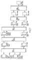
- FIG. 5 is a view showing the first processing sequence in the 3D image processing apparatus in FIG. 1;
- FIG. 6 is a view showing the second processing sequence in the 3D image processing apparatus in FIG. 1;
- FIG. 7 is a view showing the third processing sequence in the 3D image processing apparatus in FIG. 1;
- FIG. 8A is a view showing contrast images;
- FIG. 8B is a view showing mask images;
- FIG. 8C is a view showing DSA images;
- FIG. 9A is a view showing volume data corresponding to the contrast images;
- FIG. 9B is a view showing volume data corresponding to the mask images;
- FIG. 9C is a view showing volume data corresponding to the DSA images; and
- FIG. 10 is a view showing a 3D angio/bone image.
-
- As shown in FIG. 1, a 3D X-ray diagnosing apparatus has an
X-ray imaging mechanism X-ray imaging mechanism 10 has anX-ray tube 12 anddetection system 14. Thedetection system 14 is constituted by an image intensifier and TV camera.
Thedetection system 14 may be formed from a flat panel detector. TheX-ray tube 12 is mounted on a C-arm 160 together with thedetection system 14. An object P to be examined on atop 50 of a bed is placed between theX-ray tube 12 and thedetection system 14. The C-arm 160 is supported by asupport 164 suspended from the ceiling. The C-arm 160 can rotate along three orthogonal axes A, B, and C. - The 3D image processing apparatus 1 includes a
control unit 37 serving as a main component, an A/D converter 21, aninput device 22, astoring unit 23, asubtracting unit 31, adistortion correcting unit 32, anaffine converter 36, a 3Dreconstruction processing unit 33, a 3Dimage processing unit 35, animage synthesizing unit 34, a D/A converter 38, and a displayingunit 39. The A/D converter 21 is connected to thedetection system 14. The D/A converter 38 is connected to the displayingunit 39. Theinput device 22 has a keyboard and mouse. The storingunit 23 stores various data such as image data, volume data, and synthetic image data input through the A/D converter 21. The subtractingunit 31 has a function of subtracting image data and a function of subtracting image data or volume data. In the subtracting process of the former, a logarithm natural of two data is computed, and the two data are subtracted after that. In the subtracting process of the latter, a two data are subtracted directly. The former is named as the first subtracting process, and the latter is named as the second subtracting process in the following.
Thedistortion correcting unit 32 has distortion correction processing for correcting image distortion to originate in the Image Intensifie. Theaffine converter 36 performs enlargement processing and movement processing. - The 3D
reconstruction processing unit 33 reconstructs volume data from a plurality of image data corresponding to a plurality of projection directions. The 3Dimage processing unit 35 generates 3D image data from volume data by surface rendering processing. Theimage synthesizing unit 34 generates synthetic image data by synthesizing two or more kinds of 3D images. - The operation of this embodiment will be described next. A contrast media is injected into a blood vessel of the object. Before the contrast media is injected into the object, a plurality of image data corresponding to a plurality of projection directions are acquired. Images acquired before injection of the contrast media are called mask images. The mask images include an image of a bone and an image of a soft tissue. Pixel values in the respective images reflect transmittances unique to the bone and soft tissue.
- After the contrast media is injected, a plurality of image data corresponding to a plurality of projection directions are acquired. Images acquired after injection of the contrast media are called contrast images. The plurality of projection directions to which the plurality of contrast images correspond coincide with the plurality of projection directions to which the plurality of mask images correspond. The contrast images include an image of the bone, an image of the soft tissue, and an image of the blood vessel. A pixel value in the image of the bone reflects a transmittance unique to the bone.
A pixel value in the image of the soft tissue reflects a transmittance unique to the soft tissue. A pixel value in the image of the blood vessel reflects a transmittance unique to the contrast media in the blood vessel instead of the blood vessel. The transmittance of the contrast media is much lower than that of the blood vessel. - In practice, for example, imaging is repeated 200 times at 1°-intervals while the C-
arm 160 rotates (A or B) at high speed. As a consequence, 200 mask images (200 frames) are obtained. The 200 mask images correspond to 200 projection directions. The 200 contrast images obtained by imaging after injection of the contrast media correspond to the 200 projection directions. The 200 contrast images respectively correspond to the 200 mask images. A given mask image coincides in projection direction with a corresponding contrast image. - The data of the 200 mask images are stored in the storing
unit 23. Likewise, the data of the 200 contrast images are stored in the storingunit 23. These mask image data and contrast image data are subjected to distortion correction processing by thedistortion correcting unit 32, as shown in FIG. 4. For the sake of simplicity, consider, as distortion correction processing, processing using a phantom having wires arranged at equal intervals vertically and horizontally in the form of a square lattice.
When imaging is performed after this phantom is placed on the detection surface of thedetection system 14, a projection image of the phantom ideally has a square lattice shape, as shown in FIG. 3B. In practice, however, the projection image of the phantom undergoes pincushion distortion due to the shape of the detection surface of thedetection system 14 and sigmoid distortion due to geomagnetism, as shown in FIG. 3A. For this reason, the distorted image data shown in FIG. 3A is acquired in advance, and the intersections of the wires are extracted as lattice points from this distorted image data. These lattice points should be arranged at equal intervals in the absence of distortion. Therefore, correction vectors for arraying the lattice points at equal intervals are obtained for each lattice point. The mask and contrast images are corrected in accordance with the correction vectors. Points other than the lattice points are corrected by using the data of neighboring lattice points. Note that since different distortion distributions appear at different angles, a distortion distribution table measured from acquired angle-specific phantom projection images is held, and distortion is corrected on the basis of the table. - The subtracting
unit 31 corrects density non-uniformlty in a mask image. Likewise, the subtractingunit 31 corrects density non-uniformity in a contrast image. The processing for correcting density non-uniformlty subtracts a image for correcting density non-uniformity from a mask or contrast image in the first subtracting process. The image for correcting density non-uniformity is obtained by imaging in a state wherein nothing other than air is interposed between theX-ray tube 12 and thedetection system 14. - This embodiment provides three kinds of 3D image processes for separately generating 3D image data representing a bone structure and 3D image data representing a contrasted blood vessel structure. The three kinds of 3D image processes are shown in FIGS. 4, 5, and 6. A desired one of the three kinds of 3D image processing is selected by an operator through the
input device 22. An angio-image and bone image are generated by the selected process. A synthetic image of the generated angio-image and bone image is displayed. - The three kinds of 3D image processes will be sequentially described below.
- As shown in FIG. 5, in the first 3D image process, first of all, the subtracting
unit 31 subtracts a plurality of corected mask images (see FIG. 8B) in different projection directions from a plurality of corrected contrast images (see FIG. 8A) in different projection directions in the second subtracting process. When it says concretely, the respective corrected mask images are subtracted from the corresponding corrected contrast images in the same projection directions as those of the mask images.
As a consequence, a plurality of DSA images (see FIG. 8C) are generated. Each corrected mask image includes an image of a bone and an image of a soft tissue. Each corrected contrast image includes an image of the bone, an image of the soft tissue, and an image of the contrasted blood vessel. Each DSA image substantially includes only an image of the contrasted blood vessel. - A plurality of mask images are subjected to 3D reconstruction processing by the 3D
reconstruction processing unit 33. As a consequence, volume data (mask) is generated (see FIG. 9B). The volume data (mask) includes the 3D structure of the bone, the 3D structure of the soft tissue. A plurality of DSA images are subjected to 3D reconstruction processing by the 3Dreconstruction processing unit 33. As a consequence, volume data (DSA) is generated (see FIG. 9C). The volume data (DSA) includes only the 3D structure of the contrasted blood vessel. - As a reconstruction method, the filtered back projection method proposed by Feldkamp et al. is generally used. An appropriate convolution filter such as a Shepp-Logan filter or Ramachandran filter is applied to the 200 DSA images. The 200 DSA images processed by the convolution filter are then subjected to back projection operation. As a consequence, volume data (DSA) is generated. Likewise, an appropriate convolution filter is applied to the 200 corrected mask images. The 200 corrected mask images processed by the convolution filter are then subjected to back projection operation. As a consequence, volume data (mask) is generated.
- In this case, a reconstruction region is defined as a cylinder inscribed in an X-ray beam from the
X-ray tube 12 in all directions. The inside of this cylinder is three-dimensionally discretized with a length d at the central portion of the reconstruction region projected by the width of one detection element of thedetection system 14, and a reconstructed image based on the data of each discrete point must be obtained. Although an example of the discrete interval is described, this value may differ depending on the apparatus or maker. Basically, therefore, it suffices if the discrete interval defined for each apparatus be used. - The volume data (mask) is subjected to surface rendering processing by the 3D
image processing unit 35. This generates a 3D image (3D bone image) representing the 3D structure of the bone. The volume data (DSA) is subjected to surface rendering processing by the 3Dimage processing unit 35. This generates a 3D image (3D angio-image) representing the 3D structure of the contrasted blood vessel. - The surface rendering processing is processing of rearranging volume data into a 2D pixel matrix so as to render the data on the displaying
unit 39 having a 2D display screen. The image data is arranged as 2D matrix data but expresses the 3D structure of the object. In this case, therefore, this image will be referred to as a 3D image in particular. In surface rendering processing, first of all, the coordinate position of the volume data is converted to a viewpoint coordinate system. The viewpoint coordinate system for the volume data (mask) coincides with that for the volume data (DSA). In the surface rendering processing, occlusion processing and shading processing of shading an object surface are executed with respect to the converted volume data. As a consequence, 3D image data is generated. Surface rendering processing for the volume data (mask) is performed for only voxels having voxel values (CT values) within a range corresponding to the bone. This generates a 3D bone image. Surface rendering processing for the volume data (DSA) is performed for only voxels having voxel values (CT values) within a range corresponding to the contrasted blood vessel. This generates a 3D angio-image. - The
image synthesizing unit 34 generates the 3D image (mask) based on the volume data (mask) and generates the 3D image (DSA) originated from the volume data (DSA), by using the hidden plane removal processing. Theimage synthesizing unit 34 synthesizs the 3D image (mask) and the 3D image (DSA). As a consequence, a synthetic image (3D angio/bone image) is generated. - The 3D image processing of this embodiment is characterized in that the 3D image (3D bone image) representing the 3D structure of the bone and the 3D image (3D angio-image) representing the 3D structure of the contrasted blood vessel are independently generated. Therefore, the 3D structure of the blood vessel can be displayed by the color which is different from the 3D structure of the bone. The 3D structure of the blood vessel can be identified from the 3D structure of the bone. The observer can recognize the position of the blood vessel to the bone.
- The 3D angio/bone image is displayed on the displaying unit 39 (see FIG. 10). In accordance with specifying operation by the operator, 3D angio display image or 3D bone display image is singly displayed on the displaying
unit 39 in place of the 3D angio/bone image. The 3D displaying method is not limited to the surface rendering method. The volume rendering method, MIP(Maximum Intensity Projection), MinIP(Minimum Intensity Projection) or VED(Virtual Endoscopic Display) may be used. - As shown in FIG. 6, in the second 3D image process, 3D reconstruction processing is performed before subtraction processing. A plurality of mask images are subjected to 3D reconstruction processing by the 3D
reconstruction processing unit 33. This generates volume data (mask). The volume data (mask) includes the 3D structure of the bone, the 3D structure of the soft tissue. - A plurality of contrast images are subjected to 3D reconstruction processing by the 3D
reconstruction processing unit 33. This generates volume data (after injection of the contrast media) (see FIG. 9A). The volume data (after injection of the contrast media) includes the 3D structure of the bone, the 3D structure of the soft tissue, and the 3D structure of the contrasted blood vessel. - The volume data (mask) is subtracted from the volume data (contrast) by the second subtraction processing. As a consequence, volume data (DSA) including only the 3D structure of the contrasted blood vessel is generated.
- The generated volume data (mask) and volume data (DSA) are subjected to the same processing as that in the first 3D image process.
- As shown in FIG. 7, in the third 3D image process, as in the first 3D image process, first of all, a plurality of mask images are subtracted from a plurality of contrast images to generate a plurality of DSA images by the second subtraction processing.
- The 3D
reconstruction processing unit 33 then generates volume data (after injection of the contrast media) from a plurality of contrast images, and generates volume data (DSA) from a plurality of DSA images. - The volume data (DSA) is subtracted from the volume data (after injection of the contrast media). This generates volume data (mask) including the 3D structure of the bone, the 3D structure of the soft tissue.
- The generated volume data (mask) and volume data (DSA) are subjected to the same processing as that in the first 3D image process.
- In this embodiment, volume data including a bone structure and volume data including a contrasted blood vessel structure are separately generated from contrast images and mask images. Surface rendering is separately applied to the volume data including the bone structure and the volume data including the contrasted blood vessel structure. A 3D image representing the bone structure and a 3D image representing the blood vessel structure are generated. These two images are synthesized. The resultant image is then displayed. This makes it possible to display the precise blood vessel structure together with the bone structure.
- In this case, the X-ray imaging apparatus incorporates the 3D reconstruction processing unit and 3D image processing unit. However, the present invention is not limited to this, and the X-ray imaging apparatus, 3D reconstruction processing unit, and 3D image processing unit may be independently arranged in an allowable combination. Soft tissues such as internal organs may be extracted in place of the bone from the volume data (mask).
Claims (8)
- A 3D image processing apparatus characterized by comprising:a storing unit (23) configured to store data of a plurality of mask images corresponding to a plurality of projection directions associated with an object to be examined, and data of a plurality of contrast images corresponding to the plurality of projection directions associated with the object;a subtracting unit (31) configured to generate data of a plurality of subtraction images by subtracting the plurality of mask images from the plurality of contrast images;a reconstruction unit (33) configured to reconstruct first volume data from the plurality of mask images and reconstructs second volume data from the plurality of subtraction images;an image processing unit (35) configured to generate data of a first 3D image representing a bone structure and/or a soft tissue structure from the first volume data, and generates data of a second 3D image representing a contrasted blood vessel from the second volume data;an image synthesizing unit (34) configured to generate data of a synthetic image by synthesizing the first 3D image with the second 3D image; anda displaying unit (39) configured to display the synthetic image.
- A 3D image processing apparatus characterized by comprising:a storing unit (23) configured to store data of a plurality of mask images corresponding to a plurality of projection directions associated with an object to be examined, and data of a plurality of contrast images corresponding to the plurality of projection directions associated with the object;a reconstruction unit (33) configured to reconstruct first volume data from the plurality of contrast images, and to reconstruct second volume data from the plurality of mask images;a subtracting unit (31) configured to generate third volume data by subtracting the second volume data from the first volume data;an image processing unit (35) configured to generate data of a first 3D image representing a bone structure and/or a soft tissue structure from the second volume data, and to generate data of a second 3D image representing a contrasted blood vessel from the third volume data;an image synthesizing unit (34) configured to generate data of a synthetic image by synthesizing the first 3D image with the second 3D image; anda displaying unit (39) configured to display the synthetic image.
- A 3D image processing apparatus characterized by comprising:a storing unit (23) configured to store data of a plurality of mask images corresponding to a plurality of projection directions associated with an object to be examined, and data of a plurality of contrast images corresponding to the plurality of projection directions associated with the object;a subtracting unit (31) configured to generate data of a plurality of subtraction images by subtracting the plurality of mask images from the plurality of contrast images;a reconstruction unit (33) configured to reconstruct first volume data from the plurality of contrast images and to reconstruct second volume data from the plurality of subtraction images;a subtracting unit (31) configured to generate third volume data by subtracting the second volume data from the first volume data;an image processing unit (35) configured to generate data of a first 3D image representing a bone structure and/or a soft tissue structure from the third volume data, and to generate data of a second 3D image representing a contrasted blood vessel from the second volume data;an image synthesizing unit (34) configured to generate data of a synthetic image by synthesizing the first 3D image with the second 3D image; anda displaying unit (39) configured to display the synthetic image.
- A 3D image processing apparatus characterized by comprising:a storing unit (23) configured to store data of a plurality of mask images corresponding to a plurality of projection directions associated with an object to be examined, and data of a plurality of contrast images corresponding to the plurality of projection directions associated with the object;a processing unit (31) configured to generate first volume data representing structures of a bone and soft tissue and second volume data representing a structure of a contrasted blood vessel on the basis of the data of the plurality of contrast images and the data of the plurality of mask images;an image processing unit (35) configured to generate data of a first 3D image representing a bone structure and/or a soft tissue structure from the first volume data, and generates data of a second 3D image representing a contrasted blood vessel from the second volume data;an image synthesizing unit (34) configured to generate data of a synthetic image by synthesizing the first 3D image with the second 3D image; anda displaying unit (39) configured to display the synthetic image.
- An apparatus according to any one of Claims 1 to 4, characterized in that the image synthesizing unit generates data of the synthetic image such that the second 3D image is displayed in a colour different from that of the first 3D image.
- An apparatus according to any one of Claims 1 to 4, characterized in that the image synthesizing unit assigns colour information to the second 3D image independently of the first 3D image.
- An apparatus according to any one of Claims 1 to 4, characterized in that the image processing unit generates the data of the first and second 3D images by volume rendering processing.
- An apparatus according to any one of Claims 1 to 4, characterized in that the displaying unit singly displays the first 3D image or the second 3D image in place of the synthetic image in accordance with a user instruction.
Applications Claiming Priority (2)
| Application Number | Priority Date | Filing Date | Title |
|---|---|---|---|
| US649697 | 2003-08-28 | ||
| US10/649,697 US7432924B2 (en) | 2003-08-28 | 2003-08-28 | 3D digital subtraction angiography image processing apparatus |
Publications (3)
| Publication Number | Publication Date |
|---|---|
| EP1510972A2 true EP1510972A2 (en) | 2005-03-02 |
| EP1510972A3 EP1510972A3 (en) | 2006-05-17 |
| EP1510972B1 EP1510972B1 (en) | 2018-11-21 |
Family
ID=34104684
Family Applications (1)
| Application Number | Title | Priority Date | Filing Date |
|---|---|---|---|
| EP04253316.6A Expired - Lifetime EP1510972B1 (en) | 2003-08-28 | 2004-06-04 | 3D image processing apparatus |
Country Status (4)
| Country | Link |
|---|---|
| US (1) | US7432924B2 (en) |
| EP (1) | EP1510972B1 (en) |
| JP (3) | JP2005080285A (en) |
| CN (1) | CN1307597C (en) |
Cited By (5)
| Publication number | Priority date | Publication date | Assignee | Title |
|---|---|---|---|---|
| DE102006040934A1 (en) * | 2006-08-31 | 2008-03-20 | Siemens Ag | Method and apparatus for the separate three-dimensional representation of the arterial and venous vascular system with C-arm angiography systems |
| CN101732061B (en) * | 2008-11-21 | 2013-05-22 | 株式会社东芝 | Image processing apparatus and image processing method |
| CN104883978A (en) * | 2012-12-06 | 2015-09-02 | 日立阿洛卡医疗株式会社 | Ultrasonic diagnostic device and ultrasonic image display method |
| DE102016203857A1 (en) * | 2016-03-09 | 2017-09-14 | Siemens Healthcare Gmbh | Method for acquiring and processing image data of an examination object |
| EP4062835A1 (en) * | 2021-03-23 | 2022-09-28 | Koninklijke Philips N.V. | Subtraction imaging |
Families Citing this family (44)
| Publication number | Priority date | Publication date | Assignee | Title |
|---|---|---|---|---|
| US7432924B2 (en) | 2003-08-28 | 2008-10-07 | Kabushiki Kaisha Toshiba | 3D digital subtraction angiography image processing apparatus |
| US7676257B2 (en) * | 2003-11-25 | 2010-03-09 | General Electric Company | Method and apparatus for segmenting structure in CT angiography |
| US7756324B2 (en) * | 2004-11-24 | 2010-07-13 | Kabushiki Kaisha Toshiba | 3-dimensional image processing apparatus |
| US7725165B2 (en) * | 2004-12-07 | 2010-05-25 | M2S, Inc. | Method and apparatus for visualizing anatomical structures |
| JP4564387B2 (en) * | 2005-03-28 | 2010-10-20 | 株式会社東芝 | Medical image generation device |
| US8068665B2 (en) * | 2005-05-10 | 2011-11-29 | Kabushiki Kaisha Toshiba | 3D-image processing apparatus, 3D-image processing method, storage medium, and program |
| CN100539948C (en) * | 2005-10-21 | 2009-09-16 | 株式会社东芝 | Medical image processing device and medical image processing method |
| JP5085031B2 (en) * | 2005-11-10 | 2012-11-28 | 株式会社東芝 | X-ray angiography equipment |
| US7864995B2 (en) * | 2006-02-11 | 2011-01-04 | General Electric Company | Systems, methods and apparatus of handling structures in three-dimensional images |
| US7412023B2 (en) * | 2006-02-28 | 2008-08-12 | Toshiba Medical Systems Corporation | X-ray diagnostic apparatus |
| JP4820666B2 (en) * | 2006-03-01 | 2011-11-24 | 株式会社東芝 | X-ray imaging apparatus and method |
| DE102006046735A1 (en) * | 2006-09-29 | 2008-04-10 | Siemens Ag | Images e.g. two dimensional-radioscopy image and virtual endoscopy image, fusing device for C-arm device, has image fusion unit for generating image representation from segmented surface with projected image point |
| JP4895204B2 (en) * | 2007-03-22 | 2012-03-14 | 富士フイルム株式会社 | Image component separation device, method, and program, and normal image generation device, method, and program |
| US8285014B2 (en) * | 2007-04-06 | 2012-10-09 | Siemens Aktiengesellschaft | Measuring blood volume with C-arm computed tomography |
| JP2008284081A (en) * | 2007-05-16 | 2008-11-27 | Shimadzu Corp | X-ray equipment |
| US20100208971A1 (en) * | 2007-09-27 | 2010-08-19 | Koninklijke Philips Electronics N.V. | Methods for imaging the blood perfusion |
| JP5514397B2 (en) * | 2007-10-03 | 2014-06-04 | ジーイー・メディカル・システムズ・グローバル・テクノロジー・カンパニー・エルエルシー | Image display apparatus and X-ray tomography apparatus |
| FR2924255A1 (en) * | 2007-11-27 | 2009-05-29 | Gen Electric | METHOD FOR PROCESSING RADIOGRAPHIC CARDIAC IMAGES FOR OBTAINING A SUBTRACT AND RECALLED IMAGE |
| JP5388472B2 (en) * | 2008-04-14 | 2014-01-15 | キヤノン株式会社 | A control device, an X-ray imaging system, a control method, and a program for causing a computer to execute the control method. |
| JP5422171B2 (en) * | 2008-10-01 | 2014-02-19 | 株式会社東芝 | X-ray diagnostic imaging equipment |
| JP5361439B2 (en) * | 2009-02-23 | 2013-12-04 | 株式会社東芝 | Medical image processing apparatus and medical image processing method |
| JP5836047B2 (en) | 2010-10-08 | 2015-12-24 | 株式会社東芝 | Medical image processing device |
| WO2012121368A1 (en) | 2011-03-10 | 2012-09-13 | 株式会社 東芝 | Medical diagnostic imaging device, medical image display device, medical image processing device, and medical image processing program |
| JP5807354B2 (en) * | 2011-03-22 | 2015-11-10 | ソニー株式会社 | Image processing apparatus, image processing method, and program |
| JP5257958B2 (en) * | 2011-06-01 | 2013-08-07 | 株式会社日立メディコ | Image display device, image display system, and image display method |
| US8855394B2 (en) * | 2011-07-01 | 2014-10-07 | Carestream Health, Inc. | Methods and apparatus for texture based filter fusion for CBCT system and cone-beam image reconstruction |
| JP5921132B2 (en) * | 2011-10-17 | 2016-05-24 | 株式会社東芝 | Medical image processing system |
| KR101337339B1 (en) * | 2011-10-21 | 2013-12-06 | 삼성전자주식회사 | X-ray imaging apparatus and control method for the same |
| US9153045B2 (en) | 2012-03-22 | 2015-10-06 | The Cleveland Clinic Foundation | Augmented reconstruction for computed tomography |
| JP5871705B2 (en) * | 2012-04-27 | 2016-03-01 | 株式会社日立メディコ | Image display apparatus, method and program |
| CN103385755B (en) * | 2012-05-11 | 2015-04-08 | 萨摩亚商星世代股份有限公司台湾分公司 | Digital image storage system and human body data comparing method for medical treatment or cosmetology |
| JP5631931B2 (en) * | 2012-06-11 | 2014-11-26 | 株式会社東芝 | X-ray angiography equipment |
| KR102033600B1 (en) | 2012-10-19 | 2019-11-11 | 삼성전자주식회사 | Method and apparatus for measuring medical information providing 3-dimensional stereoscopic image |
| US9595088B2 (en) | 2013-11-20 | 2017-03-14 | Toshiba Medical Systems Corporation | Method of, and apparatus for, visualizing medical image data |
| CN103876764B (en) * | 2013-11-21 | 2016-03-30 | 沈阳东软医疗系统有限公司 | A kind of blood vessel developing method and device |
| JP6252195B2 (en) * | 2014-01-17 | 2017-12-27 | 富士ゼロックス株式会社 | Image processing apparatus and program |
| US9947129B2 (en) * | 2014-03-26 | 2018-04-17 | Carestream Health, Inc. | Method for enhanced display of image slices from 3-D volume image |
| JP6651402B2 (en) * | 2016-04-12 | 2020-02-19 | キヤノンメディカルシステムズ株式会社 | Medical image processing apparatus, medical image diagnostic apparatus, and program |
| JP2019158534A (en) * | 2018-03-12 | 2019-09-19 | 株式会社ミツトヨ | X-ray ct apparatus for measurement and method for generating fault image |
| US20220092785A1 (en) * | 2018-12-18 | 2022-03-24 | Agfa Nv | Method of decomposing a radiographic image into sub-images of different types |
| DE102019200888A1 (en) * | 2019-01-24 | 2020-07-30 | Siemens Healthcare Gmbh | Determine an image data set |
| DE102019202514B4 (en) * | 2019-02-25 | 2021-06-24 | Siemens Healthcare Gmbh | Process for digital subtraction angiography, X-ray equipment, computer program and electronically readable data carrier |
| CN113597567A (en) * | 2019-03-26 | 2021-11-02 | 松下知识产权经营株式会社 | Distance image acquisition method and distance detection device |
| US12257096B2 (en) * | 2022-08-24 | 2025-03-25 | Clearpoint Neuro, Inc. | Patient-specific infusion coverage estimates using segmented 3D brain representations |
Citations (1)
| Publication number | Priority date | Publication date | Assignee | Title |
|---|---|---|---|---|
| US5802133A (en) | 1995-12-01 | 1998-09-01 | Hitachi Medical Corporation | Method and apparatus of X-ray computerized tomography |
Family Cites Families (25)
| Publication number | Priority date | Publication date | Assignee | Title |
|---|---|---|---|---|
| JP2563298B2 (en) | 1987-01-28 | 1996-12-11 | 株式会社東芝 | Three-dimensional image processing device |
| JP2714164B2 (en) * | 1989-07-31 | 1998-02-16 | 株式会社東芝 | 3D image display |
| JPH05137711A (en) | 1991-11-15 | 1993-06-01 | Hitachi Medical Corp | X ray image diagnostic device |
| US5839440A (en) * | 1994-06-17 | 1998-11-24 | Siemens Corporate Research, Inc. | Three-dimensional image registration method for spiral CT angiography |
| US5782762A (en) * | 1994-10-27 | 1998-07-21 | Wake Forest University | Method and system for producing interactive, three-dimensional renderings of selected body organs having hollow lumens to enable simulated movement through the lumen |
| JPH08168487A (en) * | 1994-12-20 | 1996-07-02 | Hitachi Medical Corp | X-ray tomography and apparatus therefor |
| JP3570576B2 (en) * | 1995-06-19 | 2004-09-29 | 株式会社日立製作所 | 3D image synthesis and display device compatible with multi-modality |
| JP3770280B2 (en) * | 1996-03-29 | 2006-04-26 | 株式会社日立メディコ | 3D image display method and apparatus |
| DE19613342A1 (en) * | 1996-04-03 | 1997-10-09 | Philips Patentverwaltung | Automatic image evaluation process |
| DE19620371A1 (en) * | 1996-05-21 | 1997-12-04 | Philips Patentverwaltung | X-ray procedure |
| JP3583554B2 (en) * | 1996-07-23 | 2004-11-04 | 株式会社日立メディコ | Cone beam X-ray tomography system |
| US5712895A (en) * | 1997-01-14 | 1998-01-27 | Picker International, Inc. | Rotational digital subtraction angiography phantom |
| DE19843408C2 (en) * | 1998-09-22 | 2000-10-26 | Siemens Ag | Method for reproducing x-ray images when positioning a catheter inserted into a vessel and device for carrying out the method |
| JP2000116637A (en) * | 1998-10-12 | 2000-04-25 | Ge Yokogawa Medical Systems Ltd | Image display method and apparatus and fluoroscopic apparatus |
| JP2000237177A (en) * | 1998-12-22 | 2000-09-05 | Tetsuo Takuno | X-ray three-dimensional image photographing method and device |
| JP4473358B2 (en) * | 1999-01-21 | 2010-06-02 | 株式会社東芝 | Diagnostic equipment |
| JP3857002B2 (en) * | 1999-11-24 | 2006-12-13 | 株式会社日立メディコ | X-ray tomography method and apparatus |
| FR2813973B1 (en) * | 2000-09-08 | 2003-06-20 | Ge Med Sys Global Tech Co Llc | METHOD AND DEVICE FOR GENERATING THREE-DIMENSIONAL IMAGES AND APPARATUS FOR RADIOLOGY THEREOF |
| US20020032375A1 (en) | 2000-09-11 | 2002-03-14 | Brainlab Ag | Method and system for visualizing a body volume and computer program product |
| US6493569B2 (en) * | 2000-12-30 | 2002-12-10 | Ge Medical Systems Global Technology Company, Llc | Method and apparatus using post contrast-enhanced steady-state free precession in MR imaging |
| JP4574872B2 (en) * | 2001-02-05 | 2010-11-04 | 株式会社東芝 | 3D image display system |
| DE10122875C1 (en) * | 2001-05-11 | 2003-02-13 | Siemens Ag | Combined 3D angio volume reconstruction procedure |
| JP3499541B2 (en) * | 2001-07-25 | 2004-02-23 | ザイオソフト株式会社 | Three-dimensional image display method, apparatus and program |
| US7123760B2 (en) * | 2002-11-21 | 2006-10-17 | General Electric Company | Method and apparatus for removing obstructing structures in CT imaging |
| US7432924B2 (en) | 2003-08-28 | 2008-10-07 | Kabushiki Kaisha Toshiba | 3D digital subtraction angiography image processing apparatus |
-
2003
- 2003-08-28 US US10/649,697 patent/US7432924B2/en not_active Expired - Lifetime
-
2004
- 2004-06-04 EP EP04253316.6A patent/EP1510972B1/en not_active Expired - Lifetime
- 2004-06-09 JP JP2004171283A patent/JP2005080285A/en not_active Withdrawn
- 2004-07-28 CN CNB2004100586796A patent/CN1307597C/en not_active Expired - Lifetime
-
2010
- 2010-04-30 JP JP2010105159A patent/JP5491948B2/en not_active Expired - Fee Related
-
2013
- 2013-12-16 JP JP2013259616A patent/JP2014076388A/en not_active Abandoned
Patent Citations (1)
| Publication number | Priority date | Publication date | Assignee | Title |
|---|---|---|---|---|
| US5802133A (en) | 1995-12-01 | 1998-09-01 | Hitachi Medical Corporation | Method and apparatus of X-ray computerized tomography |
Cited By (13)
| Publication number | Priority date | Publication date | Assignee | Title |
|---|---|---|---|---|
| DE102006040934B4 (en) | 2006-08-31 | 2022-05-12 | Siemens Healthcare Gmbh | Method and device for the separate display of arteries and veins |
| US7558372B2 (en) | 2006-08-31 | 2009-07-07 | Siemens Aktiengesellschaft | Method and device for the separate three-dimensional representation of the arterial and venous vascular system using C-arm angiography systems |
| US7852984B2 (en) | 2006-08-31 | 2010-12-14 | Siemens Aktiengesellschaft | Method and device for the separate three-dimensional representation of the arterial and venous vascular system using C-arm angiography systems |
| DE102006040934A1 (en) * | 2006-08-31 | 2008-03-20 | Siemens Ag | Method and apparatus for the separate three-dimensional representation of the arterial and venous vascular system with C-arm angiography systems |
| CN101732061B (en) * | 2008-11-21 | 2013-05-22 | 株式会社东芝 | Image processing apparatus and image processing method |
| CN104883978B (en) * | 2012-12-06 | 2017-03-08 | 株式会社日立制作所 | Ultrasonic diagnostic device and ultrasonic image display method |
| CN104883978A (en) * | 2012-12-06 | 2015-09-02 | 日立阿洛卡医疗株式会社 | Ultrasonic diagnostic device and ultrasonic image display method |
| DE102016203857A1 (en) * | 2016-03-09 | 2017-09-14 | Siemens Healthcare Gmbh | Method for acquiring and processing image data of an examination object |
| DE102016203857B4 (en) * | 2016-03-09 | 2021-05-12 | Siemens Healthcare Gmbh | Method for acquiring and processing image data of an examination subject |
| US11013481B2 (en) | 2016-03-09 | 2021-05-25 | Siemens Healthcare Gmbh | Method for acquiring and processing image data of an examination object |
| EP4062835A1 (en) * | 2021-03-23 | 2022-09-28 | Koninklijke Philips N.V. | Subtraction imaging |
| WO2022200089A1 (en) * | 2021-03-23 | 2022-09-29 | Koninklijke Philips N.V. | Subtraction imaging |
| US12419600B2 (en) | 2021-03-23 | 2025-09-23 | Koninklijke Philips N.V. | Subtraction imaging |
Also Published As
| Publication number | Publication date |
|---|---|
| JP2010207591A (en) | 2010-09-24 |
| CN1307597C (en) | 2007-03-28 |
| JP5491948B2 (en) | 2014-05-14 |
| EP1510972B1 (en) | 2018-11-21 |
| EP1510972A3 (en) | 2006-05-17 |
| US7432924B2 (en) | 2008-10-07 |
| CN1591477A (en) | 2005-03-09 |
| JP2014076388A (en) | 2014-05-01 |
| JP2005080285A (en) | 2005-03-24 |
| US20050046644A1 (en) | 2005-03-03 |
Similar Documents
| Publication | Publication Date | Title |
|---|---|---|
| EP1510972B1 (en) | 3D image processing apparatus | |
| JP5085031B2 (en) | X-ray angiography equipment | |
| JP4854137B2 (en) | Medical diagnostic imaging equipment | |
| US7991105B2 (en) | Visualization of 3D images in combination with 2D projection images | |
| US8463013B2 (en) | X-ray diagnosis apparatus and image reconstruction processing apparatus | |
| US11786193B2 (en) | Metal artifacts reduction in cone beam reconstruction | |
| US7604404B2 (en) | X-ray imaging apparatus | |
| JP4482164B2 (en) | X-ray imaging method using a series of images from different viewpoints | |
| US6751284B1 (en) | Method and system for tomosynthesis image enhancement using transverse filtering | |
| US8350852B2 (en) | Device and method for reconstruction and visualization of projection data | |
| US8050471B2 (en) | Image processing system and method for displaying images during interventional procedures | |
| JP6418344B1 (en) | Computer program, image processing apparatus, and image processing method | |
| EP2115700B1 (en) | Geometry-dependent filtering in ct method and apparatus | |
| US6366635B1 (en) | Method and apparatus for three-dimensional image-rendering of a spatial and tissue-based configuration through separating high contrast and injected contrast agents in multi-angular x-ray absorption measurement | |
| JP4828920B2 (en) | 3D image processing device | |
| CN100490747C (en) | 3-dimensional image processing apparatus | |
| JP5487172B2 (en) | Medical image diagnostic apparatus and medical image processing apparatus | |
| JP4709603B2 (en) | Medical image processing device | |
| JP5631931B2 (en) | X-ray angiography equipment | |
| JP6021340B2 (en) | Medical image processing apparatus and control program | |
| EP4312772B1 (en) | Subtraction imaging | |
| WO2025125021A1 (en) | Metal artifact reduction for metal objects outside the scan field of view |
Legal Events
| Date | Code | Title | Description |
|---|---|---|---|
| PUAI | Public reference made under article 153(3) epc to a published international application that has entered the european phase |
Free format text: ORIGINAL CODE: 0009012 |
|
| 17P | Request for examination filed |
Effective date: 20040624 |
|
| AK | Designated contracting states |
Kind code of ref document: A2 Designated state(s): AT BE BG CH CY CZ DE DK EE ES FI FR GB GR HU IE IT LI LU MC NL PL PT RO SE SI SK TR |
|
| AX | Request for extension of the european patent |
Extension state: AL HR LT LV MK |
|
| PUAL | Search report despatched |
Free format text: ORIGINAL CODE: 0009013 |
|
| AK | Designated contracting states |
Kind code of ref document: A3 Designated state(s): AT BE BG CH CY CZ DE DK EE ES FI FR GB GR HU IE IT LI LU MC NL PL PT RO SE SI SK TR |
|
| AX | Request for extension of the european patent |
Extension state: AL HR LT LV MK |
|
| RIC1 | Information provided on ipc code assigned before grant |
Ipc: G06T 15/00 20060101AFI20041217BHEP Ipc: G06T 11/00 20060101ALI20060328BHEP |
|
| 17Q | First examination report despatched |
Effective date: 20060726 |
|
| AKX | Designation fees paid |
Designated state(s): DE NL |
|
| RAP1 | Party data changed (applicant data changed or rights of an application transferred) |
Owner name: TOSHIBA MEDICAL SYSTEMS CORPORATION |
|
| GRAP | Despatch of communication of intention to grant a patent |
Free format text: ORIGINAL CODE: EPIDOSNIGR1 |
|
| STAA | Information on the status of an ep patent application or granted ep patent |
Free format text: STATUS: GRANT OF PATENT IS INTENDED |
|
| INTG | Intention to grant announced |
Effective date: 20171220 |
|
| RIN1 | Information on inventor provided before grant (corrected) |
Inventor name: OHISHI, SATORU |
|
| GRAJ | Information related to disapproval of communication of intention to grant by the applicant or resumption of examination proceedings by the epo deleted |
Free format text: ORIGINAL CODE: EPIDOSDIGR1 |
|
| STAA | Information on the status of an ep patent application or granted ep patent |
Free format text: STATUS: EXAMINATION IS IN PROGRESS |
|
| GRAS | Grant fee paid |
Free format text: ORIGINAL CODE: EPIDOSNIGR3 |
|
| STAA | Information on the status of an ep patent application or granted ep patent |
Free format text: STATUS: GRANT OF PATENT IS INTENDED |
|
| INTC | Intention to grant announced (deleted) | ||
| GRAP | Despatch of communication of intention to grant a patent |
Free format text: ORIGINAL CODE: EPIDOSNIGR1 |
|
| INTG | Intention to grant announced |
Effective date: 20180608 |
|
| GRAA | (expected) grant |
Free format text: ORIGINAL CODE: 0009210 |
|
| STAA | Information on the status of an ep patent application or granted ep patent |
Free format text: STATUS: THE PATENT HAS BEEN GRANTED |
|
| AK | Designated contracting states |
Kind code of ref document: B1 Designated state(s): DE NL |
|
| REG | Reference to a national code |
Ref country code: DE Ref legal event code: R096 Ref document number: 602004053446 Country of ref document: DE |
|
| REG | Reference to a national code |
Ref country code: NL Ref legal event code: FP |
|
| REG | Reference to a national code |
Ref country code: DE Ref legal event code: R097 Ref document number: 602004053446 Country of ref document: DE |
|
| PLBE | No opposition filed within time limit |
Free format text: ORIGINAL CODE: 0009261 |
|
| STAA | Information on the status of an ep patent application or granted ep patent |
Free format text: STATUS: NO OPPOSITION FILED WITHIN TIME LIMIT |
|
| 26N | No opposition filed |
Effective date: 20190822 |
|
| PGFP | Annual fee paid to national office [announced via postgrant information from national office to epo] |
Ref country code: NL Payment date: 20230417 Year of fee payment: 20 |
|
| PGFP | Annual fee paid to national office [announced via postgrant information from national office to epo] |
Ref country code: DE Payment date: 20230412 Year of fee payment: 20 |
|
| REG | Reference to a national code |
Ref country code: DE Ref legal event code: R071 Ref document number: 602004053446 Country of ref document: DE |
|
| REG | Reference to a national code |
Ref country code: NL Ref legal event code: MK Effective date: 20240603 |