EP1510782A1 - Angular velocity sensor - Google Patents
Angular velocity sensor Download PDFInfo
- Publication number
- EP1510782A1 EP1510782A1 EP03733096A EP03733096A EP1510782A1 EP 1510782 A1 EP1510782 A1 EP 1510782A1 EP 03733096 A EP03733096 A EP 03733096A EP 03733096 A EP03733096 A EP 03733096A EP 1510782 A1 EP1510782 A1 EP 1510782A1
- Authority
- EP
- European Patent Office
- Prior art keywords
- vibrator
- angular velocity
- velocity sensor
- circuit board
- frame
- Prior art date
- Legal status (The legal status is an assumption and is not a legal conclusion. Google has not performed a legal analysis and makes no representation as to the accuracy of the status listed.)
- Withdrawn
Links
Images


Classifications
-
- G—PHYSICS
- G01—MEASURING; TESTING
- G01P—MEASURING LINEAR OR ANGULAR SPEED, ACCELERATION, DECELERATION, OR SHOCK; INDICATING PRESENCE, ABSENCE, OR DIRECTION, OF MOVEMENT
- G01P3/00—Measuring linear or angular speed; Measuring differences of linear or angular speeds
- G01P3/42—Devices characterised by the use of electric or magnetic means
- G01P3/44—Devices characterised by the use of electric or magnetic means for measuring angular speed
-
- G—PHYSICS
- G01—MEASURING; TESTING
- G01C—MEASURING DISTANCES, LEVELS OR BEARINGS; SURVEYING; NAVIGATION; GYROSCOPIC INSTRUMENTS; PHOTOGRAMMETRY OR VIDEOGRAMMETRY
- G01C19/00—Gyroscopes; Turn-sensitive devices using vibrating masses; Turn-sensitive devices without moving masses; Measuring angular rate using gyroscopic effects
- G01C19/56—Turn-sensitive devices using vibrating masses, e.g. vibratory angular rate sensors based on Coriolis forces
- G01C19/5607—Turn-sensitive devices using vibrating masses, e.g. vibratory angular rate sensors based on Coriolis forces using vibrating tuning forks
- G01C19/5628—Manufacturing; Trimming; Mounting; Housings
Definitions
- This invention generally relates to an angular velocity sensor, and more particularly, to an angular velocity sensor that employs a piezoelectric vibrator.
- An angular velocity sensor detects the angular velocity when an object is rotating.
- Angular velocity sensors are in use for avoiding blurring of images due to hand movement in taking a picture, position detection systems such as car navigation systems, and attitude control systems for automobiles and robots. Any inclination of a detection axis against a detection reference plane causes a detection error or an improper detection of another axis. In the above-mentioned case, an accurate angular velocity cannot be detected. Therefore, a control system equipped with the angular velocity sensor will suffer from various problems caused resulting from angular errors in detection.
- the angular velocity sensor is generally housed in the dashboard of a car. In the case where the control system equipped with the angular velocity sensor is installed in the dashboard, if the detection axis is parallel to the ground surface that is the reference plane, the angular velocity can be detected accurately.
- Figs. 1A and 1B show the above-mentioned case.
- the horizontal axis in Fig. 1A denotes the angle of sensor inclination (°)
- the vertical axis in Fig. 1A denotes the detection error of angular velocity (%).
- the horizontal axis in Fig. 1B denotes the angle of sensor inclination (°)
- the vertical axis in Fig. 1A denotes the detection error of angular velocity (%).
- the horizontal axis in Fig. 1B denotes the angle of sensor inclination (°)
- 1B denotes the improper detection of another axis (%).
- Another object of the present invention is to provide an angular velocity sensor that can adjust the direction of the detection axis readily.
- the angular velocity sensor according to the present invention is characterized by including a stem, and a vibrator that is supported by the stem, the vibrator being inclined to a mounting surface of the stem.
- a detection axis of the vibrator is inclined to a mounting surface, and even if the angular velocity sensor is installed on the inclined surface, it is possible to adjust the detection axis in a proper direction.
- the axis of the vibrator which is the smallest unit in the detection axis, is inclined, and it is thus possible to minimize the dead space caused resulting from the inclination.
- the angle of inclination of the vibrator to the mounting surface may be adjustable.
- the above-mentioned angular velocity sensor may further include a holding member that holds the vibrator so that the angle of inclination can be adjusted.
- the holding member may be elastically deformable, and holds the vibrator.
- the holding member may have a single member that is folded.
- the above-mentioned angular velocity sensor may further include a vibrator supporting substrate that secures the vibrator, a circuit board and a frame that holds the vibrator supporting substrate and the circuit board. The axis of the vibrator is inclined within the surface parallel to the circuit board, and it is thus minimize the dead space.
- the above-mentioned angular velocity sensor may further include a vibrator supporting substrate that secures the vibrator, a circuit board, and a frame that holds the vibrator supporting substrate and the circuit board, and the frame sandwiches and holds the vibrator supporting substrate.
- the above-mentioned angular velocity sensor may further include a vibrator supporting substrate that secures the vibrator, a circuit board, and a frame that holds the vibrator supporting substrate and the circuit board, and the frame may be made of an elastically deformable material so that an angle to the mounting surface can be adjusted.
- the frame may be engaged with multiple sides of the circuit board.
- the above-mentioned angular velocity sensor may further include a vibrator supporting substrate that secures the vibrator, a circuit board, and a frame that holds the vibrator supporting substrate and the circuit board, and the circuit board is arranged on a first side of the frame and the vibrator and the vibrator supporting substrate are arranged on a second side of the frame.
- the vibrator supporting substrate may have a concave portion
- the frame has a holding member that is fit into the concave portion.
- the angular velocity sensor may be connected to electrodes that are arranged on the vibrator, and has external connection terminals that pierce the stem.
- the above-mentioned angular velocity sensor may further include a circuit board on which a circuitry to be connected to the vibrator is arranged, and pads for external connection are provided on a surface of the circuit board.
- the above-mentioned angular velocity sensor may further include a frame that is provided to cover the circuit board, and a circuit board holding portion of the frame is in contact with pads, the circuit board holding portion being engaged with the circuit board.
- the above-mentioned angular velocity sensor may further include a vibrator supporting substrate that secures the vibrator, a circuit board, and a frame that holds the vibrator supporting substrate and the circuit board, and the vibrator supporting substrate is composed of multiple layers.
- the vibrator is a tuning fork vibrator or a vibrating reed vibrator having a block shape.
- the vibrator may be held by a plurality of holding members that are elastically deformable.
- the angular velocity sensor according to the present invention is characterized by including a stem, a vibrator, and a holding member that holds the vibrator on the stem, and the holding member is elastically deformable and an angle of a detection axis is adjustable by elastically deforming the holding member.
- the holding member may hold the vibrator so that the detection axis of the vibrator may be inclined to a mounting surface of the stem.
- the holding member may hold the vibrator so that the detection axis of the vibrator may be parallel to a mounting surface of the stem.
- Figs. 2 and 3 are perspective views of an angular velocity sensor in accordance with a first embodiment of the present invention.
- Fig. 2 shows a case where the angle of inclination of a vibrator is 0°.
- Fig. 3 shows a case where the vibrator is inclined.
- the angular sensor includes a stem 10, a vibrator 12, a vibrator supporting substrate 14, a frame 16, a holding member 18, a circuit board 20, and multiple external connection terminals 21.
- the holding member 18 is made of elastically deformable material.
- the angle of the vibrator 12 can be adjusted arbitrarily by elastically deforming the holding member 18, as shown in Fig. 3.
- the angular velocity sensor in Fig. 3 is suitable for the case where the angular velocity sensor or the system having the same is installed on the surface that is inclined to the reference plane.
- the angular velocity sensor is installed so that a mounting surface 11 of the stem 10 may substantially be parallel to a motherboard of the system having the vibrator 12.
- the circuit board 20 is installed substantially vertical to the stem 10 or the mounting surface 11.
- the vibrator 12 is inclined on a plane parallel to the circuit board 20.
- the angle of inclination can be adjusted readily by elastically deforming the holding member 18 that is made of an elastically deformable material.
- the angular velocity sensors as shown in Figs. 2 and 3 can be set vertical to the reference plane readily regardless of the angle of inclination, even if the surface on which the angular velocity sensor is installed is inclined such as the dashboard. It goes without saying that the detection axis of the sensor is vertical to the reference plane, when the sensor is installed. In the case where the angle of inclination is predetermined when the vibrator 12 is installed, the vibrator 12 is secured at the predetermined angle in advance to produce the holding member 18 with the material that is not elastically deformed. Components of the angular velocity sensor in accordance with the first embodiment of the present invention will be described in detail.
- Figs. 4A and 4B are perspective views of the vibrator 12.
- Fig. 4A shows a surface side of the vibrator 12.
- Fig. 4B shows a backside of the vibrator 12.
- the vibrator 12 is a tuning fork vibrator including two arms 22 and 24 and a base 26. The base 26 joins the arms 22 and 24.
- the vibrator 12 is made of piezoelectric material. For example, a single crystal piezoelectric material such as LiNbO 3 and LiTaO 3 is used.
- the detection axis of the vibrator 12 is a direction in which the two arms extend.
- a detecting electrode and a driving electrode are formed as follows. Detecting electrodes 34, 38, and 39 are arranged in the arm 22.
- Detecting electrodes 32, 36, and 37 are arranged in the arm 24.
- the detecting electrodes 38 and 39 are coupled via a round electrode 30 that wraps around an upper part of the arm 22.
- the detecting electrode 38 is connected to an extraction electrode 41, which extends toward the base 26.
- the detecting electrode 34 is arranged on an external side face of the arm 22.
- the detecting electrode 34 is extracted onto the base 26 by an extraction electrode 42.
- the detecting electrodes 36 and 37 are connected together on a round electrode 28 that wraps around an upper part of the arm 24.
- the detecting electrode 36 is connected to an extraction electrode 43 that is arranged on the base 26.
- the detecting electrode 32 is arranged on an external side face of the arm 24, and is extracted onto the base 26 by an extraction electrode 40.
- the driving electrode 44 is arranged on the surface side with a U-shape pattern.
- the U-shape pattern is formed on the arms 22 and 24.
- the driving electrode 44 is extracted onto the surface of the base 26 by an extraction electrode 48.
- the driving electrode 46 is arranged on the backside with a U-shape pattern.
- the U-shape pattern is formed on the arms 22 and 24.
- the driving electrode 46 is extracted onto the backside of the base 26 by an extraction electrode 50.
- Figs. 5A, through 5C illustrate a vibrator supporting substrate 14.
- Fig. 5A is a top view of the supporting substrate 14.
- Fig. 5B is a cross sectional view taken along a line V B -V B shown in Fig. 5A.
- Fig. 5C is a bottom view of the supporting substrate 14.
- the vibrator supporting substrate 14 has a three-layer structure composed of substrates 14 1 , 14 2 , and 14 3 , which are made of aluminum, for example.
- a concave portion 53 is formed in the substrates 14 1 and 14 2 .
- the base 26 of the vibrator 12 is fit into the concave portion 53.
- Pads 52 are arranged around the concave portion 53 as shown in Fig. 5A.
- An electrode 54 is arranged on the bottom.
- the electrode 54 is coupled to one of the pads 52 through an internal via connection.
- the extraction electrode 50 which is shown in Fig. 4B, comes into contact with the electrode 54.
- a conductive adhesive agent is applied to the concave portion 53 to secure the vibrator 12 to the vibrator supporting substrate 14.
- the extraction electrodes 40, 41, 42, 43, and 48 which are arranged on the surface of the vibrator 12, are electrically coupled to the corresponding pads 52 with the use of bonding wires or conductive paste, for example.
- the vibrator 12 also includes another concave portion 56.
- the concave portion 56 and the concave portion 53 face each other.
- the concave portion 56 penetrates through the three layers 4 1 , 14 2 , and 14 3 of the vibrator supporting substrate 14.
- the holding member 18 is fit into the concave portion 56, and is secured with a silicon-based adhesive agent, for example.
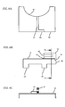
- Figs. 6A through 6C illustrate a frame 16 and the holding member 18.
- Fig. 6A is a top view of the frame 16 and the holding member 18.
- Fig. 6B is a side view of the frame 16 and the supporting member 18.
- Fig. 6C is a cross sectional view taken along a line VI C -VI C shown in Fig. 6B.
- the frame 16 is made of a conductive material, for example, nickel-plated cobal or nickel-plated phosphor bronze.
- the frame 16 has a C-shape of cross section, and has circuit board holding portions 58 on the side face thereof. The circuit board holding portions 58 are engaged with the circuit board 20. Specifically, as shown in Figs.
- a cut out portion 60 having the C-shape is arranged on the side face of the circuit board 20.
- the circuit board holding portions 58 are engaged with corners of the cut out portion 60. That is, the circuit board holding portions 58 hold the circuit board 20 by sandwiching the side faces of the circuit board 20.
- the circuit board holding portions 58 are secured to the circuit board 20 with the use of adhesive or solder.
- the circuit board holding portions 58 are engaged with the side faces of the circuit board 20, as described. Instead, holes may be provided inside the circuit board 20 so as to insert the circuit board holding portions 58. In addition, other methods may be employed so as to hold the circuit board 20.
- the frame 16 has the C-shape of cross section, and a gap is created between the circuit board 20 and the inner surface of the frame 16.
- This gap prevents electronic parts mounted on the circuit board 20 from touching the frame 16. Additionally, the frame 16 has an arch-shape of cut out portion 65. An electric connection is established between the vibrator supporting substrate 14 and the circuit board 20 by interconnection lines that pass through the cut out portion 65, such as wires or the like.
- the holding member 18 is arranged on the vibrator supporting substrate 14. Referring to Fig. 6B, the holding member 18 has a C-shape of cross section.
- the vibrator supporting substrate 14 is fit into a gap 62 created by the holding member 18.
- the vibrator supporting substrate 14 is attached onto the holding member 18 so that the inner surface, on which the pads 52 are provided, may face the frame 16.
- the holding member 18 includes a holding part 64.
- the holding part 64 is secured onto a bottom portion 66 of the frame 16 with the use of an adhesive agent.
- a concave portion that corresponds to the holding part 64 is formed on the bottom portion 66 of the frame 16, and is engaged with the holding part 64.
- the holding member 18 is also made of a conductive material, for example, nickel-plated cobal or nickel-plated phosphor bronze, in the same manner as the frame 16. This means that the holding member 18 is elastically deformable, as indicated by an arrow in Fig. 6A. A slight gap 70 is created between the bottom face of the holding member 18 and the top face of the frame 16. The gap 70 is provided so that the angle of the frame 16 to the bottom portion 66 may be adjusted readily by the elastically deforming the holding member 18. The holding member 18 is elastically deformed to adjust the angle of the frame 16 to the bottom portion 66. This makes it possible to adjust the angle of inclination of the detection axis of the vibrator 12.
- the frame 16 and the holding member 18 may be formed with a single member 68.
- Fig. 7 is a developed view of the single member 68.
- the single member 68 is folded as shown.
- the developed holding member 18 is folded as shown in (1) in Fig. 7 to have a C-shape, and is folded at the center of the holding part 64 as shown in (2) in Fig. 7.
- the holding part 64 is a part of the single member 68.
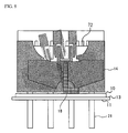
- Fig. 8 is a front view of the angular velocity sensor.
- Fig. 8 shows a combined view of Figs. 2 and 3.
- a referential numeral 72 shows electronic components such as IC, resistor, and capacitor. These electronic components 72 are mounted on the circuit board 20, and are coupled via an interconnection pattern that is arranged on the circuit board 20. The circuitry formed on the circuit board 20 will be described later in detail.
- a cap which is not shown, is attached to a flange 13 shown in Figs. 2, 3, and 8. The cap seals the vibrator 12 and the circuit board 20 to protect the inside of the angular velocity sensor.
- Figs. 9A through 9C show the stem 10.
- Fig. 9A is a front view
- Fig. 9B is a plain view
- Fig. 9C is a side view.
- the external connection terminal 21 has a pin-shape, and six external connection terminals 21 are provided in accordance with the first embodiment of the present invention. These external connection terminals 21 pierce the stem 10.
- Upper parts 21A of four external connection terminals 21 are arranged in line, and are circled for a better understanding as shown in Figs. 9A through 9C.
- the upper parts 21A are in contact with pads that are arranged on the backside of the circuit board 20, as will be described later in detail.
- Lower parts of the external connection terminals 21 are inserted into holes that are formed on a substrate such as a motherboard, and are secured by soldering. Upper parts 22B of the remaining two external connection terminals 21 are not in contact with the pads arranged on the circuit board 20. That is, the upper parts 22B are shorter than the upper parts.
- the above-mentioned two external connection terminals 21 may be dummy terminals, and may actually be used as external connection terminals.
- Fig. 10 is a back view of the angular velocity sensor.
- Pads 74 and 76 are arranged on the backside of the circuit board 20.
- the pads 74 are respectively soldered onto the upper parts 21A of the external connection terminals 21.
- the circuit board holding portions 58 of the frame 16 are folded inward, and are soldered onto the pads 76.
- Two of the four external connection terminals 21 respectively serve as a signal terminal and a ground terminal to apply driving signals.
- the remaining two external connection terminals 21 also serve as the signal terminal and the ground terminal to output angular velocity detecting signals.
- the pads 76 serve as ground terminals of the circuitry that is arranged on the circuit board 20.
- the circuitry is electronically coupled to the frame 16 through the multiple pads 16, and the frame 16 serves as an extremely excellent shield.
- the pads 76 may be omitted.
- the shield may be connected to the external connection terminals 21 that serve as the ground on the circuit board 20.
- the shield serves as the shield.
- Fig. 11A is a circuit diagram provided on the circuit board 20.
- Fig. 11B shows a connection diagram of the detection electrodes 32, 34, 36, 37, 38, and 39.
- a driving signal input terminal 78, a driving circuit 80, a differential amplifier 82, a low pass filter (LPF) 84, a direct-current amplifier 86, and a detection signal output terminal 88 are arranged on the circuit board 20.
- the driving signal input terminal 78 and the detection signal output terminal 88 correspond to the pads 74 as shown in Fig. 10.
- the driving circuit 80 receives the driving signals from the outside through the driving signal input terminal 78, and applies a driving voltage to the driving electrodes 44 and 46.
- the two arms 22 and 24, to which the driving voltage has been applied, conduct in-plane vibration.
- the differential amplifier 82 differentially amplifies the voltages of the detecting electrodes 38, 39, and 32 and those of the detecting electrodes 36, 37, and 34.
- the driving circuit 80 operates in synchronization with the differential amplifier 82.
- An output voltage from the differential amplifier 82 passes through the LPF 84, and is amplified by the direct-current amplifier 86.
- Direct current voltage outputted from the direct-current amplifier 86 is applied to the detection signal output terminal 88 as an angular velocity detection signal.
- the angular velocity sensor includes the stem 10 and the vibrator 12 that is supported by the stem 10.
- the vibrator 12 is inclined to the mounting surface 11 of the stem 10.
- the detection axis can be set in a proper direction, that is, the direction perpendicular to the reference plane such as the ground surface, even if the surface on which the angular velocity sensor is installed is inclined to the ground surface.
- the angle of inclination of the vibrator 12 to the mounting surface 11 is adjustable, and it is possible to install the angular velocity sensor at an arbitrary angle.
- the angular velocity sensor includes the holding member 18 that is elastically deformable, and the holding member 18 holds the vibrator 12.
- the angular velocity sensor has a relatively simple structure including the vibrator supporting substrate 14, the circuit board 20, and the frame 16.
- the frame 16 holds the vibrator supporting substrate 14 and the circuit board 20.
- the angular velocity sensor is capable of adjusting the angle of the detection axis arbitrarily.
- the frame 16 also has a simple structure, sandwiching and holding the vibrator supporting substrate 14. In the case where the frame 16 and the holding member 18 are made of a single member, the frame 16 is made of an elastically deformable material.
- the frame 16 is engaged with multiple sides of the circuit board 20, and is capable of supporting the circuit board 20 readily.
- the circuit board 20 is arranged on a first side of the frame 16, and the vibrator 12 and the vibrator supporting substrate 14 are arranged on a second side of the frame 16.
- the angular velocity sensor has a compact structure.
- the vibrator supporting substrate 14 includes the concave portion 53, and the frame 16 includes a holding member that is fit into the concave portion 53. It is thus easy to assemble and is possible to hold the vibrator 12 securely.
- the angular velocity sensor is connected to electrodes (such as the driving electrodes and the detecting electrodes) that are arranged on the vibrator 12, and includes the multiple external connection terminals 21 that pierce the stem 10.
- the angular velocity sensor is able to connect to the outside readily.
- the angular velocity sensor includes the circuit board 20 on which the circuitry connecting to the vibrator 12 is arranged (Figs. 11A and 11B).
- the pads 76 are arranged on the circuit board surface so as to connect to the outside. Therefore, the angular velocity sensor has a great flexibility when connected to the outside.
- the angular velocity sensor includes the frame 16 that is arranged to cover the circuit board 20.
- the circuit board holding portions 58 of the frame 16, which is engaged with the circuit board 20, are in contact with the pads 76.
- the frame 16 can serve as a shield member readily.
- the angular velocity sensor includes the stem 10, the vibrator 12, and the holding member 18 that holds the vibrator 12 on the stem 10.
- the holding member 18 is elastically deformable.
- the angle of the detection axis of the vibrator 12 is adjustable by elastically deforming the holding member 18. It is thus possible to set the detection axis to be vertical to the reference plane, even if the angular velocity sensor is inclined to the reference plane.
- Figs. 12A and 12B are front views of an angular velocity sensor in accordance with a second embodiment of the present invention.
- the second embodiment of the present invention is a variation of the first embodiment of the present invention.
- Fig. 12A includes the vibrator 12, the vibrator supporting substrate 14, the frame 16, the holding member 18, and the circuit board 20 of the first embodiment, which are rotated 90 degrees clockwise.
- Fig. 12B includes the vibrator 12, the vibrator supporting substrate 14, and the holding member 18 that are rotated 90 degrees clockwise.
- the holding member'18 is parallel to the mounting surface 11 of the stem 10
- the detection axis is parallel to the mounting surface 11.
- the holding member 18 can be inclined to the mounting surface 11.
- Fig. 12B the holding member 18 is parallel to the mounting surface 11 of the stem 10, and the detection axis is parallel to the mounting surface 11.
- the holding member 18 is rotated clockwise, the holding member 18 can be inclined to the mounting surface 11.
- the angular velocity sensor with the above-mentioned configuration has the same mechanism and effects as in the first embodiment of the present invention.
- the first and the second embodiments of the present invention have the same size substantially, and thereby to produce the angular velocity sensors having an identical size, although the sensors have different detection axes. This makes it possible to arrange and mount the angular velocity sensors with a great flexibility.
- Fig. 13 is a front view of the angular velocity sensor in accordance with a third embodiment of the present invention.
- a block-shape of a vibrating reed vibrator 92 is employed for the vibrator.
- Two holding members 98A and 98B hold around the edges of a longer side of the block-shape of the vibrating reed vibrator 92.
- the holding members 98A and 98B are part of the frame 96. That is, a single member is folded to shape the frame 96 and the holding members 98A and 98B.
- the holding member 98A is arranged on the upper side of the frame 96, and is tilted counterclockwise.
- the holding member 98B is arranged on the lower side of the frame 96, which is in a diagonal relationship with the holding member 98A, and is tilted counterclockwise at the same degrees as the holding member 98A.
- the vibrating reed vibrator 92 is held by those holding members 98A and 98B.
- the conventional techniques may be employed for the driving electrodes and the detecting electrodes.
- the above-mentioned electrodes and the circuit board 20 are connected by the use of wires or the like.
- the detection axis of the vibrating reed vibrator 92 is arbitrarily adjustable by elastically deforming the two holding members 98A and 98B.
- the present invention provides the angular velocity sensor that can appropriately adjust the detection axis to the reference plane for the angular velocity detection, even if the sensor is installed on an inclined surface.
- the present invention also provides the angular velocity sensor that can adjust the direction of the detection axis readily.
Abstract
Description
- This invention generally relates to an angular velocity sensor, and more particularly, to an angular velocity sensor that employs a piezoelectric vibrator.
- An angular velocity sensor detects the angular velocity when an object is rotating. Angular velocity sensors are in use for avoiding blurring of images due to hand movement in taking a picture, position detection systems such as car navigation systems, and attitude control systems for automobiles and robots. Any inclination of a detection axis against a detection reference plane causes a detection error or an improper detection of another axis. In the above-mentioned case, an accurate angular velocity cannot be detected. Therefore, a control system equipped with the angular velocity sensor will suffer from various problems caused resulting from angular errors in detection. For example, with respect to a car navigation system, the angular velocity sensor is generally housed in the dashboard of a car. In the case where the control system equipped with the angular velocity sensor is installed in the dashboard, if the detection axis is parallel to the ground surface that is the reference plane, the angular velocity can be detected accurately.
- The dashboards of a number of cars, however, are not parallel to the ground surface. In the case where the control system is installed in an inclined dashboard, the detection axis of the angular velocity sensor is also inclined, the detection error of the angular velocity becomes greater, and similarly, the improper detection of another axis occurs more often. Figs. 1A and 1B show the above-mentioned case. The horizontal axis in Fig. 1A denotes the angle of sensor inclination (°), and the vertical axis in Fig. 1A denotes the detection error of angular velocity (%). The horizontal axis in Fig. 1B denotes the angle of sensor inclination (°), and the vertical axis in Fig. 1B denotes the improper detection of another axis (%). In addition, it is necessary to newly install a tilting table in a dashboard or attach the tilting table to the sensor, if the detection axis of the sensor needs to be parallel to the ground surface. As a result, a larger space is required.
- It is a general object of the present invention to solve the above-mentioned drawback and provide an angular velocity sensor that can adjust the detection axis appropriately to the detection reference plane of the angular velocity even if the sensor is installed on an inclined surface and that can downsize the whole system.
- Another object of the present invention is to provide an angular velocity sensor that can adjust the direction of the detection axis readily.
- In order to achieve the above-mentioned objectives, the angular velocity sensor according to the present invention is characterized by including a stem, and a vibrator that is supported by the stem, the vibrator being inclined to a mounting surface of the stem. A detection axis of the vibrator is inclined to a mounting surface, and even if the angular velocity sensor is installed on the inclined surface, it is possible to adjust the detection axis in a proper direction. In addition, the axis of the vibrator, which is the smallest unit in the detection axis, is inclined, and it is thus possible to minimize the dead space caused resulting from the inclination. In the above-mentioned angular velocity sensor, the angle of inclination of the vibrator to the mounting surface may be adjustable. The above-mentioned angular velocity sensor may further include a holding member that holds the vibrator so that the angle of inclination can be adjusted. In the above-mentioned angular velocity sensor, the holding member may be elastically deformable, and holds the vibrator. In the above-mentioned angular velocity sensor, the holding member may have a single member that is folded. The above-mentioned angular velocity sensor may further include a vibrator supporting substrate that secures the vibrator, a circuit board and a frame that holds the vibrator supporting substrate and the circuit board. The axis of the vibrator is inclined within the surface parallel to the circuit board, and it is thus minimize the dead space. The above-mentioned angular velocity sensor may further include a vibrator supporting substrate that secures the vibrator, a circuit board, and a frame that holds the vibrator supporting substrate and the circuit board, and the frame sandwiches and holds the vibrator supporting substrate. The above-mentioned angular velocity sensor may further include a vibrator supporting substrate that secures the vibrator, a circuit board, and a frame that holds the vibrator supporting substrate and the circuit board, and the frame may be made of an elastically deformable material so that an angle to the mounting surface can be adjusted. In the above-mentioned angular velocity sensor, the frame may be engaged with multiple sides of the circuit board. The above-mentioned angular velocity sensor may further include a vibrator supporting substrate that secures the vibrator, a circuit board, and a frame that holds the vibrator supporting substrate and the circuit board, and the circuit board is arranged on a first side of the frame and the vibrator and the vibrator supporting substrate are arranged on a second side of the frame. In the above-mentioned angular velocity sensor, the vibrator supporting substrate may have a concave portion, and the frame has a holding member that is fit into the concave portion. In the above-mentioned angular velocity sensor, the angular velocity sensor may be connected to electrodes that are arranged on the vibrator, and has external connection terminals that pierce the stem. The above-mentioned angular velocity sensor may further include a circuit board on which a circuitry to be connected to the vibrator is arranged, and pads for external connection are provided on a surface of the circuit board. The above-mentioned angular velocity sensor may further include a frame that is provided to cover the circuit board, and a circuit board holding portion of the frame is in contact with pads, the circuit board holding portion being engaged with the circuit board. The above-mentioned angular velocity sensor may further include a vibrator supporting substrate that secures the vibrator, a circuit board, and a frame that holds the vibrator supporting substrate and the circuit board, and the vibrator supporting substrate is composed of multiple layers. In the above-mentioned angular velocity sensor, preferably, the vibrator is a tuning fork vibrator or a vibrating reed vibrator having a block shape. In the above-mentioned angular velocity sensor, the vibrator may be held by a plurality of holding members that are elastically deformable.
- The angular velocity sensor according to the present invention is characterized by including a stem, a vibrator, and a holding member that holds the vibrator on the stem, and the holding member is elastically deformable and an angle of a detection axis is adjustable by elastically deforming the holding member. In the above-mentioned angular velocity sensor, the holding member may hold the vibrator so that the detection axis of the vibrator may be inclined to a mounting surface of the stem. In the above-mentioned angular velocity sensor, the holding member may hold the vibrator so that the detection axis of the vibrator may be parallel to a mounting surface of the stem.
- Preferred embodiments of the present invention will be described in detail with reference to the following drawings, wherein:
- Figs. 1A and 1B are graphs describing drawbacks of the conventional techniques;
- Fig. 2 is a perspective view of an angular velocity sensor in accordance with a first embodiment of the present invention;
- Fig. 3 is another perspective view of the angular velocity sensor in accordance with the first embodiment of the present invention;
- Fig. 4A shows a surface side of a vibrator in accordance with the first embodiment of the present invention;
- Fig. 4B shows a backside of the vibrator in accordance with the first embodiment of the present invention;
- Fig. 5A is a top view of a supporting substrate in accordance with the first embodiment of the present invention;
- Fig. 5B is a cross sectional view taken along a line VB-VB shown in Fig. 5A.
- Fig. 5C is a bottom view of the supporting substrate in accordance with the first embodiment of the present invention;
- Fig. 6A is a top view of a frame and a holding member in accordance with the first embodiment of the present invention;
- Fig. 6B is a side view of the frame and the holding member in accordance with the first embodiment of the present invention;
- Fig. 6C is a cross sectional view taken along a line VIC-VIC shown in Fig. 6B;
- Fig. 7 is a developed view of the frame and the holding member made of an elastically deformable member in accordance with the first embodiment of the present invention;
- Fig. 8 is a front view of the angular velocity sensor in accordance with the first embodiment of the present invention;
- Fig. 9A is a front view of the stem in accordance with the first embodiment of the present invention;
- Fig. 9B is a plain view of the stem in accordance with the first embodiment of the present invention;
- Fig. 9C is a side view of the stem in accordance with the first embodiment of the present invention;
- Fig. 10 is a back view of the angular velocity sensor in accordance with the first embodiment of the present invention;
- Fig. 11A is a circuit diagram provided on a circuit board in accordance with the first embodiment of the present invention;
- Fig. 11B shows a connection diagram of detection electrodes in accordance with the first embodiment of the present invention;
- Figs. 12A and 12B are front views of an angular velocity sensor in accordance with a second embodiment of the present invention; and
- Fig. 13 is a front view of the angular velocity sensor in accordance with a third embodiment of the present invention.
-
- A description will now be given, with reference to the accompanying drawings, of embodiments of the present invention.
- A description will be given of a first embodiment of the present invention, with reference to drawings. Figs. 2 and 3 are perspective views of an angular velocity sensor in accordance with a first embodiment of the present invention. Fig. 2 shows a case where the angle of inclination of a vibrator is 0°. Fig. 3 shows a case where the vibrator is inclined. The angular sensor includes a
stem 10, avibrator 12, avibrator supporting substrate 14, aframe 16, a holdingmember 18, acircuit board 20, and multipleexternal connection terminals 21. The holdingmember 18 is made of elastically deformable material. The angle of thevibrator 12 can be adjusted arbitrarily by elastically deforming the holdingmember 18, as shown in Fig. 3. The angular velocity sensor shown in Fig. 2 is suitable for the case where thestem 10 is installed on the surface that is parallel to the reference plane (the ground surface), or where the detection axis of thevibrator 12 is vertical to the reference plane (the ground surface) even if the system having the angular velocity sensor is installed on the surface inclined to the reference plane. In contrast, as shown in Fig. 3, the detection axis of theangular velocity sensor 12 is vertical to the reference plane, which is the ground surface, in the case where thevibrator 12 or the system equipped with thevibrator 12 is installed on the inclined surface to the reference plane (the ground surface). That is, the angular velocity sensor in Fig. 3 is suitable for the case where the angular velocity sensor or the system having the same is installed on the surface that is inclined to the reference plane. The angular velocity sensor is installed so that a mountingsurface 11 of thestem 10 may substantially be parallel to a motherboard of the system having thevibrator 12. Thecircuit board 20 is installed substantially vertical to thestem 10 or the mountingsurface 11. Thevibrator 12 is inclined on a plane parallel to thecircuit board 20. The angle of inclination can be adjusted readily by elastically deforming the holdingmember 18 that is made of an elastically deformable material. - The angular velocity sensors as shown in Figs. 2 and 3 can be set vertical to the reference plane readily regardless of the angle of inclination, even if the surface on which the angular velocity sensor is installed is inclined such as the dashboard. It goes without saying that the detection axis of the sensor is vertical to the reference plane, when the sensor is installed. In the case where the angle of inclination is predetermined when the
vibrator 12 is installed, thevibrator 12 is secured at the predetermined angle in advance to produce the holdingmember 18 with the material that is not elastically deformed. Components of the angular velocity sensor in accordance with the first embodiment of the present invention will be described in detail. - Figs. 4A and 4B are perspective views of the
vibrator 12. Fig. 4A shows a surface side of thevibrator 12. Fig. 4B shows a backside of thevibrator 12. Thevibrator 12 is a tuning fork vibrator including twoarms base 26. Thebase 26 joins thearms vibrator 12 is made of piezoelectric material. For example, a single crystal piezoelectric material such as LiNbO3 and LiTaO3 is used. The detection axis of thevibrator 12 is a direction in which the two arms extend. In thearms electrodes arm 22. Detectingelectrodes arm 24. The detectingelectrodes round electrode 30 that wraps around an upper part of thearm 22. The detectingelectrode 38 is connected to anextraction electrode 41, which extends toward thebase 26. The detectingelectrode 34 is arranged on an external side face of thearm 22. The detectingelectrode 34 is extracted onto the base 26 by anextraction electrode 42. The detectingelectrodes round electrode 28 that wraps around an upper part of thearm 24. The detectingelectrode 36 is connected to anextraction electrode 43 that is arranged on thebase 26. The detectingelectrode 32 is arranged on an external side face of thearm 24, and is extracted onto the base 26 by anextraction electrode 40. The drivingelectrode 44 is arranged on the surface side with a U-shape pattern. The U-shape pattern is formed on thearms electrode 44 is extracted onto the surface of the base 26 by anextraction electrode 48. The drivingelectrode 46 is arranged on the backside with a U-shape pattern. The U-shape pattern is formed on thearms electrode 46 is extracted onto the backside of the base 26 by anextraction electrode 50. - Figs. 5A, through 5C illustrate a
vibrator supporting substrate 14. Fig. 5A is a top view of the supportingsubstrate 14. Fig. 5B is a cross sectional view taken along a line VB-VB shown in Fig. 5A. Fig. 5C is a bottom view of the supportingsubstrate 14. Referring to Fig. 5B, thevibrator supporting substrate 14 has a three-layer structure composed ofsubstrates concave portion 53 is formed in thesubstrates base 26 of thevibrator 12 is fit into theconcave portion 53.Pads 52 are arranged around theconcave portion 53 as shown in Fig. 5A. Anelectrode 54 is arranged on the bottom. Theelectrode 54 is coupled to one of thepads 52 through an internal via connection. When thevibrator 12 is fit into theconcave portion 53, theextraction electrode 50, which is shown in Fig. 4B, comes into contact with theelectrode 54. A conductive adhesive agent is applied to theconcave portion 53 to secure thevibrator 12 to thevibrator supporting substrate 14. Theextraction electrodes vibrator 12, are electrically coupled to thecorresponding pads 52 with the use of bonding wires or conductive paste, for example. Thevibrator 12 also includes anotherconcave portion 56. Theconcave portion 56 and theconcave portion 53 face each other. Theconcave portion 56 penetrates through the threelayers vibrator supporting substrate 14. The holdingmember 18 is fit into theconcave portion 56, and is secured with a silicon-based adhesive agent, for example. - Figs. 6A through 6C illustrate a
frame 16 and the holdingmember 18. Fig. 6A is a top view of theframe 16 and the holdingmember 18. Fig. 6B is a side view of theframe 16 and the supportingmember 18. Fig. 6C is a cross sectional view taken along a line VIC-VIC shown in Fig. 6B. Theframe 16 is made of a conductive material, for example, nickel-plated cobal or nickel-plated phosphor bronze. Theframe 16 has a C-shape of cross section, and has circuitboard holding portions 58 on the side face thereof. The circuitboard holding portions 58 are engaged with thecircuit board 20. Specifically, as shown in Figs. 2 and 3, a cut outportion 60 having the C-shape is arranged on the side face of thecircuit board 20. The circuitboard holding portions 58 are engaged with corners of the cut outportion 60. That is, the circuitboard holding portions 58 hold thecircuit board 20 by sandwiching the side faces of thecircuit board 20. The circuitboard holding portions 58 are secured to thecircuit board 20 with the use of adhesive or solder. The circuitboard holding portions 58 are engaged with the side faces of thecircuit board 20, as described. Instead, holes may be provided inside thecircuit board 20 so as to insert the circuitboard holding portions 58. In addition, other methods may be employed so as to hold thecircuit board 20. Theframe 16 has the C-shape of cross section, and a gap is created between thecircuit board 20 and the inner surface of theframe 16. This gap prevents electronic parts mounted on thecircuit board 20 from touching theframe 16. Additionally, theframe 16 has an arch-shape of cut outportion 65. An electric connection is established between thevibrator supporting substrate 14 and thecircuit board 20 by interconnection lines that pass through the cut outportion 65, such as wires or the like. - The holding
member 18 is arranged on thevibrator supporting substrate 14. Referring to Fig. 6B, the holdingmember 18 has a C-shape of cross section. Thevibrator supporting substrate 14 is fit into agap 62 created by the holdingmember 18. In this case, thevibrator supporting substrate 14 is attached onto the holdingmember 18 so that the inner surface, on which thepads 52 are provided, may face theframe 16. The holdingmember 18 includes a holdingpart 64. The holdingpart 64 is secured onto abottom portion 66 of theframe 16 with the use of an adhesive agent. A concave portion that corresponds to the holdingpart 64 is formed on thebottom portion 66 of theframe 16, and is engaged with the holdingpart 64. The holdingmember 18 is also made of a conductive material, for example, nickel-plated cobal or nickel-plated phosphor bronze, in the same manner as theframe 16. This means that the holdingmember 18 is elastically deformable, as indicated by an arrow in Fig. 6A. Aslight gap 70 is created between the bottom face of the holdingmember 18 and the top face of theframe 16. Thegap 70 is provided so that the angle of theframe 16 to thebottom portion 66 may be adjusted readily by the elastically deforming the holdingmember 18. The holdingmember 18 is elastically deformed to adjust the angle of theframe 16 to thebottom portion 66. This makes it possible to adjust the angle of inclination of the detection axis of thevibrator 12. - Referring to Fig. 7, the
frame 16 and the holdingmember 18 may be formed with asingle member 68. Fig. 7 is a developed view of thesingle member 68. Thesingle member 68 is folded as shown. The developed holdingmember 18 is folded as shown in (1) in Fig. 7 to have a C-shape, and is folded at the center of the holdingpart 64 as shown in (2) in Fig. 7. In this case, as a matter of course, the holdingpart 64 is a part of thesingle member 68. - Fig. 8 is a front view of the angular velocity sensor. Fig. 8 shows a combined view of Figs. 2 and 3. A
referential numeral 72 shows electronic components such as IC, resistor, and capacitor. Theseelectronic components 72 are mounted on thecircuit board 20, and are coupled via an interconnection pattern that is arranged on thecircuit board 20. The circuitry formed on thecircuit board 20 will be described later in detail. A cap, which is not shown, is attached to aflange 13 shown in Figs. 2, 3, and 8. The cap seals thevibrator 12 and thecircuit board 20 to protect the inside of the angular velocity sensor. - Figs. 9A through 9C show the
stem 10. Fig. 9A is a front view, Fig. 9B is a plain view, and Fig. 9C is a side view. Theexternal connection terminal 21 has a pin-shape, and sixexternal connection terminals 21 are provided in accordance with the first embodiment of the present invention. Theseexternal connection terminals 21 pierce thestem 10.Upper parts 21A of fourexternal connection terminals 21 are arranged in line, and are circled for a better understanding as shown in Figs. 9A through 9C. Theupper parts 21A are in contact with pads that are arranged on the backside of thecircuit board 20, as will be described later in detail. Lower parts of theexternal connection terminals 21 are inserted into holes that are formed on a substrate such as a motherboard, and are secured by soldering. Upper parts 22B of the remaining twoexternal connection terminals 21 are not in contact with the pads arranged on thecircuit board 20. That is, the upper parts 22B are shorter than the upper parts. The above-mentioned twoexternal connection terminals 21 may be dummy terminals, and may actually be used as external connection terminals. - Fig. 10 is a back view of the angular velocity sensor.
Pads circuit board 20. Thepads 74 are respectively soldered onto theupper parts 21A of theexternal connection terminals 21. The circuitboard holding portions 58 of theframe 16 are folded inward, and are soldered onto thepads 76. Two of the fourexternal connection terminals 21 respectively serve as a signal terminal and a ground terminal to apply driving signals. The remaining twoexternal connection terminals 21 also serve as the signal terminal and the ground terminal to output angular velocity detecting signals. Thepads 76 serve as ground terminals of the circuitry that is arranged on thecircuit board 20. The circuitry is electronically coupled to theframe 16 through themultiple pads 16, and theframe 16 serves as an extremely excellent shield. Thepads 76 may be omitted. In this case, the shield may be connected to theexternal connection terminals 21 that serve as the ground on thecircuit board 20. Thus, the shield serves as the shield. - Fig. 11A is a circuit diagram provided on the
circuit board 20. Fig. 11B shows a connection diagram of thedetection electrodes signal input terminal 78, a drivingcircuit 80, adifferential amplifier 82, a low pass filter (LPF) 84, a direct-current amplifier 86, and a detectionsignal output terminal 88 are arranged on thecircuit board 20. The drivingsignal input terminal 78 and the detectionsignal output terminal 88 correspond to thepads 74 as shown in Fig. 10. The drivingcircuit 80 receives the driving signals from the outside through the drivingsignal input terminal 78, and applies a driving voltage to the drivingelectrodes arms arms differential amplifier 82 differentially amplifies the voltages of the detectingelectrodes electrodes circuit 80 operates in synchronization with thedifferential amplifier 82. An output voltage from thedifferential amplifier 82 passes through theLPF 84, and is amplified by the direct-current amplifier 86. Direct current voltage outputted from the direct-current amplifier 86 is applied to the detectionsignal output terminal 88 as an angular velocity detection signal. - The features of the first embodiment of the present invention will be enumerated as follows. The angular velocity sensor includes the
stem 10 and thevibrator 12 that is supported by thestem 10. Thevibrator 12 is inclined to the mountingsurface 11 of thestem 10. Thus, the detection axis can be set in a proper direction, that is, the direction perpendicular to the reference plane such as the ground surface, even if the surface on which the angular velocity sensor is installed is inclined to the ground surface. The angle of inclination of thevibrator 12 to the mountingsurface 11 is adjustable, and it is possible to install the angular velocity sensor at an arbitrary angle. The angular velocity sensor includes the holdingmember 18 that is elastically deformable, and the holdingmember 18 holds thevibrator 12. It is thus possible to set the detection axis of thevibrator 12 in a desired direction, by elastically deforming the holdingmember 18. The holdingmember 18, which is made of a single material, is folded. Therefore, it is easy to produce the holdingmember 18. The angular velocity sensor has a relatively simple structure including thevibrator supporting substrate 14, thecircuit board 20, and theframe 16. Theframe 16 holds thevibrator supporting substrate 14 and thecircuit board 20. The angular velocity sensor is capable of adjusting the angle of the detection axis arbitrarily. Theframe 16 also has a simple structure, sandwiching and holding thevibrator supporting substrate 14. In the case where theframe 16 and the holdingmember 18 are made of a single member, theframe 16 is made of an elastically deformable material. Theframe 16 is engaged with multiple sides of thecircuit board 20, and is capable of supporting thecircuit board 20 readily. Thecircuit board 20 is arranged on a first side of theframe 16, and thevibrator 12 and thevibrator supporting substrate 14 are arranged on a second side of theframe 16. Thus, the angular velocity sensor has a compact structure. Thevibrator supporting substrate 14 includes theconcave portion 53, and theframe 16 includes a holding member that is fit into theconcave portion 53. It is thus easy to assemble and is possible to hold thevibrator 12 securely. The angular velocity sensor is connected to electrodes (such as the driving electrodes and the detecting electrodes) that are arranged on thevibrator 12, and includes the multipleexternal connection terminals 21 that pierce thestem 10. Thus, the angular velocity sensor is able to connect to the outside readily. The angular velocity sensor includes thecircuit board 20 on which the circuitry connecting to thevibrator 12 is arranged (Figs. 11A and 11B). Thepads 76 are arranged on the circuit board surface so as to connect to the outside. Therefore, the angular velocity sensor has a great flexibility when connected to the outside. The angular velocity sensor includes theframe 16 that is arranged to cover thecircuit board 20. The circuitboard holding portions 58 of theframe 16, which is engaged with thecircuit board 20, are in contact with thepads 76. Thus, theframe 16 can serve as a shield member readily. In addition, the angular velocity sensor includes thestem 10, thevibrator 12, and the holdingmember 18 that holds thevibrator 12 on thestem 10. The holdingmember 18 is elastically deformable. The angle of the detection axis of thevibrator 12 is adjustable by elastically deforming the holdingmember 18. It is thus possible to set the detection axis to be vertical to the reference plane, even if the angular velocity sensor is inclined to the reference plane. - Figs. 12A and 12B are front views of an angular velocity sensor in accordance with a second embodiment of the present invention. The second embodiment of the present invention is a variation of the first embodiment of the present invention. Fig. 12A includes the
vibrator 12, thevibrator supporting substrate 14, theframe 16, the holdingmember 18, and thecircuit board 20 of the first embodiment, which are rotated 90 degrees clockwise. Fig. 12B includes thevibrator 12, thevibrator supporting substrate 14, and the holdingmember 18 that are rotated 90 degrees clockwise. Referring to Fig. 12A, the holding member'18 is parallel to the mountingsurface 11 of thestem 10, and the detection axis is parallel to the mountingsurface 11. However, if the holdingmember 18 is rotated counterclockwise, the holdingmember 18 can be inclined to the mountingsurface 11. Referring to Fig. 12B, the holdingmember 18 is parallel to the mountingsurface 11 of thestem 10, and the detection axis is parallel to the mountingsurface 11. However, if the holdingmember 18 is rotated clockwise, the holdingmember 18 can be inclined to the mountingsurface 11. - The angular velocity sensor with the above-mentioned configuration has the same mechanism and effects as in the first embodiment of the present invention. In addition, in the case of employing the two angular velocity sensors respectively in accordance with the first and the second embodiments of the present invention together, it is possible to detect two angular velocities according to the two detection axes. Also, it is possible that the first and the second embodiments of the present invention have the same size substantially, and thereby to produce the angular velocity sensors having an identical size, although the sensors have different detection axes. This makes it possible to arrange and mount the angular velocity sensors with a great flexibility. Further, it is possible to detect three angular velocities according to the three detection axes, by adding another angular velocity sensor in accordance with the second embodiment of the present invention.
- Fig. 13 is a front view of the angular velocity sensor in accordance with a third embodiment of the present invention. A block-shape of a vibrating
reed vibrator 92 is employed for the vibrator. Two holdingmembers reed vibrator 92. The holdingmembers frame 96. That is, a single member is folded to shape theframe 96 and the holdingmembers member 98A is arranged on the upper side of theframe 96, and is tilted counterclockwise. The holdingmember 98B is arranged on the lower side of theframe 96, which is in a diagonal relationship with the holdingmember 98A, and is tilted counterclockwise at the same degrees as the holdingmember 98A. The vibratingreed vibrator 92 is held by those holdingmembers circuit board 20 are connected by the use of wires or the like. - As described, with the angular velocity sensor that employs the vibrating
reed vibrator 92, the detection axis of the vibratingreed vibrator 92 is arbitrarily adjustable by elastically deforming the two holdingmembers - The first through third embodiments of the present invention have been described.
- The present invention provides the angular velocity sensor that can appropriately adjust the detection axis to the reference plane for the angular velocity detection, even if the sensor is installed on an inclined surface. In addition, the present invention also provides the angular velocity sensor that can adjust the direction of the detection axis readily.
- The present invention is not limited to the above-mentioned embodiments, and other embodiments, variations and modifications may be made without departing from the scope of the present invention.
Claims (21)
- An angular velocity sensor characterized by comprising: a stem; and a vibrator supported by the stem, wherein the vibrator is inclined to a mounting surface of the stem.
- The angular velocity sensor as claimed in claim 1, characterized in that an angle of inclination of the vibrator to the mounting surface is adjustable.
- The angular velocity sensor as claimed in claim 1, characterized by further comprising a holding member that holds the vibrator so that the angle of inclination can be adjusted.
- The angular velocity sensor as claimed in claim 1, characterized in that the holding member is elastically deformable, and holds the vibrator.
- The angular velocity sensor as claimed in claim 4, characterized in that the holding member has a single member that is folded.
- The angular velocity sensor as claimed in claim 1, characterized by further comprising: a vibrator supporting substrate that secures the vibrator; a circuit board; and a frame that holds the vibrator supporting substrate and the circuit board.
- The angular velocity sensor as claimed in claim 1, characterized by further comprising: a vibrator supporting substrate that secures the vibrator; a circuit board; and a frame that holds the vibrator supporting substrate and the circuit board, wherein the frame sandwiches and holds the vibrator supporting substrate.
- The angular velocity sensor as claimed in claim 1, characterized by further comprising: a vibrator supporting substrate that secures the vibrator; a circuit board; and a frame that holds the vibrator supporting substrate and the circuit board, wherein the frame is made of an elastically deformable material so that an angle to the mounting surface can be adjusted.
- The angular velocity sensor as claimed in claim 1, characterized by further comprising: a vibrator supporting substrate that secures the vibrator; a circuit board; and a frame that holds the vibrator supporting substrate and the circuit board, wherein the frame is engaged with multiple sides of the circuit board.
- The angular velocity sensor as claimed in claim 1, characterized by further comprising: a vibrator supporting substrate that secures the vibrator; a circuit board; and a frame that holds the vibrator supporting substrate and the circuit board, wherein the circuit board is arranged on a first side of the frame and the vibrator and the vibrator supporting substrate are arranged on a' second side of the frame.
- The angular velocity sensor as claimed in any one of the claims 6 through 10, characterized in that: the vibrator supporting substrate has a concave portion; and the frame has a holding member that is fit into the concave portion.
- The angular velocity sensor as claimed in any one of the claims 1 through 11, characterized in that the angular velocity sensor is connected to electrodes that are arranged on the vibrator, and has external connection terminals that pierce the stem.
- The angular velocity sensor as claimed in one of the claims 1 through 12, characterized by further comprising a circuit board on which a circuitry to be connected to the vibrator is arranged, wherein pads for external connection are provided on a surface of the circuit board.
- The angular velocity sensor as claimed in claim 13, characterized by further comprising a frame that is provided to cover the circuit board, wherein a circuit board holding portion of the frame is in contact with pads, the circuit board holding portion being engaged with the circuit board.
- The angular velocity sensor as claimed in claim 1, characterized by further comprising: a vibrator supporting substrate that secures the vibrator; a circuit board; and a frame that holds the vibrator supporting substrate and the circuit board, wherein the vibrator supporting substrate is composed of multiple layers.
- The angular velocity sensor as claimed in any one of the claims 1 through 15, characterized in that the vibrator is a tuning fork vibrator.
- The angular velocity sensor as claimed in any one of the claims 1 through 15, characterized in that the vibrator is a vibrating reed vibrator.
- The angular velocity sensor as claimed in claim 1, characterized in that the vibrator is a block shape of a vibrating reed vibrator.
- An angular velocity sensor characterized by comprising: a stem; a vibrator; and a holding member that holds the vibrator on the stem, wherein: the holding member is elastically deformable; and an angle of a detection axis is adjustable by elastically deforming the holding member.
- The angular velocity sensor as claimed in claim 19, characterized in that the holding member holds the vibrator so that the detection axis of the vibrator may be inclined to a mounting surface of the stem.
- The angular velocity sensor as claimed in claim 19, characterized in that the holding member holds the vibrator so that the detection axis of the vibrator may be parallel to a mounting surface of the stem.
Applications Claiming Priority (3)
| Application Number | Priority Date | Filing Date | Title |
|---|---|---|---|
| JP2002154651 | 2002-05-28 | ||
| JP2002154651 | 2002-05-28 | ||
| PCT/JP2003/006605 WO2003100350A1 (en) | 2002-05-28 | 2003-05-27 | Angular velocity sensor |
Publications (2)
| Publication Number | Publication Date |
|---|---|
| EP1510782A1 true EP1510782A1 (en) | 2005-03-02 |
| EP1510782A4 EP1510782A4 (en) | 2006-09-20 |
Family
ID=29561377
Family Applications (1)
| Application Number | Title | Priority Date | Filing Date |
|---|---|---|---|
| EP03733096A Withdrawn EP1510782A4 (en) | 2002-05-28 | 2003-05-27 | Angular velocity sensor |
Country Status (6)
| Country | Link |
|---|---|
| US (1) | US7096733B2 (en) |
| EP (1) | EP1510782A4 (en) |
| JP (1) | JP4084354B2 (en) |
| KR (1) | KR100625736B1 (en) |
| CN (1) | CN100510631C (en) |
| WO (1) | WO2003100350A1 (en) |
Cited By (2)
| Publication number | Priority date | Publication date | Assignee | Title |
|---|---|---|---|---|
| EP1724551A2 (en) | 2005-04-14 | 2006-11-22 | Siemens Aktiengesellschaft | Holder system |
| EP1847802A1 (en) * | 2006-04-20 | 2007-10-24 | Fujitsu Media Devices Limited | Angular velocity sensor |
Families Citing this family (13)
| Publication number | Priority date | Publication date | Assignee | Title |
|---|---|---|---|---|
| JP4859347B2 (en) * | 2004-02-18 | 2012-01-25 | セイコーエプソン株式会社 | Vibrating gyroscope |
| CN1934413B (en) | 2004-03-19 | 2011-07-20 | 西铁城控股株式会社 | Oscillation device and method of manufacturing the same |
| JP2007071672A (en) * | 2005-09-06 | 2007-03-22 | Fujitsu Media Device Kk | Angular velocity sensor |
| JP4968741B2 (en) * | 2006-01-13 | 2012-07-04 | シチズンホールディングス株式会社 | Vibrating body for angular velocity sensor |
| JP2010002427A (en) * | 2006-08-09 | 2010-01-07 | Epson Toyocom Corp | Inertial sensor, inertial sensor device and its manufacturing method |
| JP5622347B2 (en) | 2006-08-09 | 2014-11-12 | セイコーエプソン株式会社 | Inertial sensor device |
| US8127829B2 (en) | 2006-09-06 | 2012-03-06 | United Technologies Corporation | Metal foam heat exchanger |
| JP2008139054A (en) * | 2006-11-30 | 2008-06-19 | Epson Toyocom Corp | Angular velocity sensor |
| CN102132128A (en) * | 2008-09-02 | 2011-07-20 | 株式会社村田制作所 | Tuning-fork vibrator and method for manufacturing the same and angular speed sensor |
| US8256288B2 (en) * | 2008-12-16 | 2012-09-04 | Seiko Epson Corporation | Sensor device |
| US8359920B2 (en) * | 2009-05-15 | 2013-01-29 | Lockheed Martin Corp. | Gravity sensing instrument |
| CN103292809B (en) * | 2013-05-14 | 2016-03-09 | 哈尔滨工程大学 | A kind of single shaft rotary inertial navigation system and special error method of self compensation thereof |
| CN106227156A (en) * | 2016-08-17 | 2016-12-14 | 上海航天测控通信研究所 | A kind of tilter kinetic control system |
Citations (4)
| Publication number | Priority date | Publication date | Assignee | Title |
|---|---|---|---|---|
| JPH09318364A (en) * | 1996-05-29 | 1997-12-12 | Tokin Corp | Piezoelectric oscillation gyro |
| JPH10267660A (en) * | 1997-03-27 | 1998-10-09 | Sumitomo Electric Ind Ltd | Mechanism for adjusting attaching angle of gyro |
| JP2002022452A (en) * | 2000-07-11 | 2002-01-23 | Ngk Insulators Ltd | Angular velocity measuring instrument containing oscillation type gyroscope |
| EP1335186A1 (en) * | 2002-02-04 | 2003-08-13 | Pioneer Corporation | Sensing apparatus comprising a sensing unit supported by a supporting unit and electronic equipment comprising said sensing apparatus |
Family Cites Families (3)
| Publication number | Priority date | Publication date | Assignee | Title |
|---|---|---|---|---|
| JPH10197254A (en) | 1997-01-07 | 1998-07-31 | Alps Electric Co Ltd | Supporting device for vibrator |
| WO1999002943A1 (en) * | 1997-07-10 | 1999-01-21 | Mitsubishi Denki Kabushiki Kaisha | Mechanism for changing attaching angle of built-in gyrosensor and method of mounting mechanism for changing attaching angle |
| JPH1194554A (en) * | 1997-09-17 | 1999-04-09 | Fujitsu Ltd | Tuning fork type piezoelectric oscillation gyro |
-
2003
- 2003-05-27 JP JP2004507764A patent/JP4084354B2/en not_active Expired - Fee Related
- 2003-05-27 KR KR1020047019159A patent/KR100625736B1/en not_active IP Right Cessation
- 2003-05-27 WO PCT/JP2003/006605 patent/WO2003100350A1/en active Application Filing
- 2003-05-27 EP EP03733096A patent/EP1510782A4/en not_active Withdrawn
- 2003-05-27 CN CNB038120771A patent/CN100510631C/en not_active Expired - Fee Related
-
2004
- 2004-11-29 US US10/998,167 patent/US7096733B2/en not_active Expired - Fee Related
Patent Citations (4)
| Publication number | Priority date | Publication date | Assignee | Title |
|---|---|---|---|---|
| JPH09318364A (en) * | 1996-05-29 | 1997-12-12 | Tokin Corp | Piezoelectric oscillation gyro |
| JPH10267660A (en) * | 1997-03-27 | 1998-10-09 | Sumitomo Electric Ind Ltd | Mechanism for adjusting attaching angle of gyro |
| JP2002022452A (en) * | 2000-07-11 | 2002-01-23 | Ngk Insulators Ltd | Angular velocity measuring instrument containing oscillation type gyroscope |
| EP1335186A1 (en) * | 2002-02-04 | 2003-08-13 | Pioneer Corporation | Sensing apparatus comprising a sensing unit supported by a supporting unit and electronic equipment comprising said sensing apparatus |
Non-Patent Citations (4)
| Title |
|---|
| PATENT ABSTRACTS OF JAPAN vol. 1998, no. 04, 31 March 1998 (1998-03-31) -& JP 09 318364 A (TOKIN CORP), 12 December 1997 (1997-12-12) * |
| PATENT ABSTRACTS OF JAPAN vol. 1999, no. 01, 29 January 1999 (1999-01-29) -& JP 10 267660 A (SUMITOMO ELECTRIC IND LTD), 9 October 1998 (1998-10-09) * |
| PATENT ABSTRACTS OF JAPAN vol. 2002, no. 05, 3 May 2002 (2002-05-03) -& JP 2002 022452 A (NGK INSULATORS LTD), 23 January 2002 (2002-01-23) * |
| See also references of WO03100350A1 * |
Cited By (3)
| Publication number | Priority date | Publication date | Assignee | Title |
|---|---|---|---|---|
| EP1724551A2 (en) | 2005-04-14 | 2006-11-22 | Siemens Aktiengesellschaft | Holder system |
| EP1724551A3 (en) * | 2005-04-14 | 2008-08-20 | Continental Automotive GmbH | Holder system |
| EP1847802A1 (en) * | 2006-04-20 | 2007-10-24 | Fujitsu Media Devices Limited | Angular velocity sensor |
Also Published As
| Publication number | Publication date |
|---|---|
| KR20040106587A (en) | 2004-12-17 |
| JP4084354B2 (en) | 2008-04-30 |
| CN1656356A (en) | 2005-08-17 |
| WO2003100350A1 (en) | 2003-12-04 |
| US7096733B2 (en) | 2006-08-29 |
| JPWO2003100350A1 (en) | 2005-09-22 |
| EP1510782A4 (en) | 2006-09-20 |
| US20050120794A1 (en) | 2005-06-09 |
| CN100510631C (en) | 2009-07-08 |
| KR100625736B1 (en) | 2006-09-21 |
Similar Documents
| Publication | Publication Date | Title |
|---|---|---|
| US7096733B2 (en) | Angular velocity sensor | |
| KR100779352B1 (en) | Angular velocity sensor | |
| EP1707920A2 (en) | Angular velocity sensor | |
| US20050028590A1 (en) | Sensing apparatus and electronic equipment utilizing same | |
| CN105758395B (en) | Physical quantity sensor, electronic apparatus, and moving object | |
| JP3341661B2 (en) | Vibrating gyro | |
| US10563983B2 (en) | Physical quantity sensor, electronic apparatus, and moving object | |
| EP1353146A1 (en) | Angular velocity sensor | |
| US6880399B1 (en) | Angular velocity sensor | |
| US7051592B2 (en) | Angular velocity sensor | |
| US6907783B2 (en) | Vibrating gyroscope and angular velocity sensor | |
| JP2006229121A (en) | Piezoelectric device, piezoelectric equipment and electronic apparatus | |
| US8689630B2 (en) | Inertial force sensor and detecting element used for same | |
| CN112311348A (en) | Vibration device, electronic apparatus, and moving object | |
| EP1760429A2 (en) | Angular velocity sensor | |
| JPH07202283A (en) | Piezoelectric sensor and its manufacture | |
| JP2006058060A (en) | Gyro sensor and electronic device | |
| JP4554971B2 (en) | Gyro device | |
| US11121689B2 (en) | Sensor failure prediction system, sensor failure prediction method, physical quantity sensor, electronic apparatus, and vehicle | |
| JP2017211255A (en) | Electronic device, manufacturing method thereof, physical quantity sensor, electronic apparatus, and mobile body | |
| JP2001194144A (en) | Inclination detecting unit | |
| JP2002014112A (en) | Piezoelectric type acceleration sensor | |
| JPH08320333A (en) | Acceleration sensor | |
| JP2000283763A (en) | Rhombic quadrangular-prism tripod tuning-fork oscillator and angular velocity sensor | |
| JP2004264083A (en) | Three-axis acceleration sensor |
Legal Events
| Date | Code | Title | Description |
|---|---|---|---|
| PUAI | Public reference made under article 153(3) epc to a published international application that has entered the european phase |
Free format text: ORIGINAL CODE: 0009012 |
|
| 17P | Request for examination filed |
Effective date: 20041222 |
|
| AK | Designated contracting states |
Kind code of ref document: A1 Designated state(s): AT BE BG CH CY CZ DE DK EE ES FI FR GB GR HU IE IT LI LU MC NL PT RO SE SI SK TR |
|
| RBV | Designated contracting states (corrected) |
Designated state(s): DE FR GB |
|
| A4 | Supplementary search report drawn up and despatched |
Effective date: 20060818 |
|
| 17Q | First examination report despatched |
Effective date: 20070102 |
|
| RAP1 | Party data changed (applicant data changed or rights of an application transferred) |
Owner name: TAMAGAWA SEIKI CO., LTD. |
|
| RAP1 | Party data changed (applicant data changed or rights of an application transferred) |
Owner name: TAMAGAWA SEIKI CO., LTD. |
|
| GRAP | Despatch of communication of intention to grant a patent |
Free format text: ORIGINAL CODE: EPIDOSNIGR1 |
|
| RIC1 | Information provided on ipc code assigned before grant |
Ipc: G01C 19/5628 20120101ALI20170426BHEP Ipc: G01C 19/5607 20120101AFI20170426BHEP |
|
| INTG | Intention to grant announced |
Effective date: 20170519 |
|
| RIN1 | Information on inventor provided before grant (corrected) |
Inventor name: TAKAHASHI, KATSUHIKO Inventor name: OHTA, KAZUHIRO, Inventor name: YACHI, MASANORI, |
|
| STAA | Information on the status of an ep patent application or granted ep patent |
Free format text: STATUS: THE APPLICATION IS DEEMED TO BE WITHDRAWN |
|
| 18D | Application deemed to be withdrawn |
Effective date: 20170930 |
|
| RIC1 | Information provided on ipc code assigned before grant |
Ipc: G01C 19/5607 20120101AFI20170426BHEP Ipc: G01C 19/5628 20120101ALI20170426BHEP |
|
| RIC1 | Information provided on ipc code assigned before grant |
Ipc: G01C 19/5628 20120101ALI20170426BHEP Ipc: G01C 19/5607 20120101AFI20170426BHEP |