EP1510774A1 - An alignment device for a firearm - Google Patents
An alignment device for a firearm Download PDFInfo
- Publication number
- EP1510774A1 EP1510774A1 EP04020340A EP04020340A EP1510774A1 EP 1510774 A1 EP1510774 A1 EP 1510774A1 EP 04020340 A EP04020340 A EP 04020340A EP 04020340 A EP04020340 A EP 04020340A EP 1510774 A1 EP1510774 A1 EP 1510774A1
- Authority
- EP
- European Patent Office
- Prior art keywords
- aperture
- cover
- firearm
- alignment device
- sighting
- Prior art date
- Legal status (The legal status is an assumption and is not a legal conclusion. Google has not performed a legal analysis and makes no representation as to the accuracy of the status listed.)
- Withdrawn
Links
Images


Classifications
-
- F—MECHANICAL ENGINEERING; LIGHTING; HEATING; WEAPONS; BLASTING
- F41—WEAPONS
- F41G—WEAPON SIGHTS; AIMING
- F41G1/00—Sighting devices
- F41G1/06—Rearsights
- F41G1/16—Adjusting mechanisms therefor; Mountings therefor
- F41G1/17—Convertible sights, i.e. sets of two or more sights brought into the sight line optionally
-
- F—MECHANICAL ENGINEERING; LIGHTING; HEATING; WEAPONS; BLASTING
- F41—WEAPONS
- F41G—WEAPON SIGHTS; AIMING
- F41G1/00—Sighting devices
- F41G1/06—Rearsights
- F41G1/08—Rearsights with aperture ; tubular or of ring form; Peep sights
Definitions
- the present invention relates to an alignment device for a firearm particularly, but not exclusively, a shotgun.
- a problem with long barrelled firearms such as shotguns and rifles is that the firearm does not necessarily fit the prospective user with the result that the user's line of sight down the gun barrel (and more particularly down the rib) is skewed in a horizontal plane, a vertical plane or both. This will result in inaccuracy in the user's aim when firing the weapon. Whether or not a particular firearm fits a particular individual can depend on, amongst other things, the length of the individual's neck and the distance between the individual's cheekbone and eye.
- a first aspect of the invention provides an alignment device for a firearm, the alignment device being mountable on said firearm and being shaped to define, in at least one mode of use, a sighting aperture located adjacent a base of the device such that, when the base is positioned, in use, on a surface of the firearm, the sighting aperture is located adjacent said surface.
- the sighting bead can be framed in the sighting aperture when a user looks along the barrel of the firearm.
- the device is typically mounted on the in use upper surface of the barrel(s), or the rib, of the firearm.
- said sighting aperture is open-ended such that, when fitted to said surface, the sighting aperture opens onto said surface.
- the device comprises a body shaped to define elongate aperture having a longitudinal axis extending in a first direction; and a cover mountable on the body and including at least one aperture that is at least partially in register with said elongate aperture during use, the body and the cover being movable with respect to one another substantially in said first direction.
- the cover is slidable with respect to the body.
- said elongate aperture is open-ended, opening onto the base of the device.
- the cover typically includes a notch formed in an edge of the cover and, when the cover is mounted on the body in at least one mode of use, the edge is located substantially at the base of the device.
- the notch is located substantially in register with the open end of said elongate aperture.
- the notch may be located beyond the body with respect to the base.
- the cover includes first and second apertures, each of said first and second apertures being located substantially in register with the longitudinal axis of the elongate aperture when the cover is mounted on the body. Either of said first or second apertures may provide a sighting aperture (typically in conjunction with the elongate aperture in the body), depending on the mode of use of the device.
- the first aperture preferably comprises said notch and said second aperture comprises an elongate aperture extending substantially in said first direction.
- the at least one aperture of the cover advantageously terminates in a cross piece, the cross piece obscuring part of said elongate aperture when the cover is mounted on the body in at least one mode of use.
- the first aperture is located substantially at one edge of the cover, the second aperture being located adjacent the opposite edge of the cover, said cross piece being defined between said second aperture and said opposite edge. In another embodiment, said cross piece is defined between the first and second apertures.
- the device is mountable in a frame, the frame being mountable on at least one barrel of a firearm, the device being slidable with respect to the frame generally in said first direction.
- the cover when mounted on the body, may obscure at least part of said elongate aperture depending on the relative position of the cover on the body. In one mode of operation, this allows the length of the sighting aperture to be adjusted depending on the relative position of the cover of the body.
- said elongate aperture is open-ended and extends from the base of the body.
- said cover is shaped to define a notch at one edge which, when the cover is mounted to the body, may be positioned in register with the elongate aperture.
- the cover includes a second elongate aperture which, when the cover is mounted on the body, may be at least partially in register with said first elongate aperture.
- the sighting aperture need not necessarily be adjacent the base of the alignment device.
- an alignment device for a firearm, the alignment device being mountable on a surface of the firearm and being shaped to define a sighting aperture, wherein the device comprises a body shaped to define elongate aperture having a longitudinal axis extending in a first direction; and a cover mountable on the body and including an elongate aperture having a longitudinal axis extending in said first direction and being at least partially in register with said elongate aperture of the body when the cover is mounted on the body in at least one mode of use, the body and the cover being movable with respect to one another substantially in said first direction, the sighting aperture being defined by the overlap between the respective elongate apertures of the cover and the body.
- a method of fitting a firearm to a user using an alignment device of the first aspect of the invention involves holding the firearm in a firing position; looking through a sighting aperture provided by the device; and determining that the firearm fits the user if the foresight of the firearm is correctly (typically wholly) visible through the sighting aperture.
- the method involves positioning the sighting aperture on or adjacent the in use upper surface of the barrel(s), or rib, of the firearm.
- the method involves positioning the sighting aperture above, or spaced-apart from, the in use upper surface of the barrel(s), or rib, of the firearm.
- a set up mode with a correctly fitting firearm held in a firing position, the position of the sighting aperture is adjusted until the foresight of the firearm is visible (usually wholly visible) through the sighting aperture.
- an alignment device embodying the invention is generally indicated as 10.
- the alignment device 10 comprises a first component part in the form of a body 12 and a second component part in the form of a cover 14.
- the body and the cover are enumerated as 112 and 114 respectively. It will be seen that the body 112 and the cover 114 are generally similar to the body 12 and the cover 14 and the following descriptions apply, in the main, to both embodiments.
- the body 12 is shaped to define an elongate aperture 16 which extends to, or substantially to, a base side 18 of the body.
- the aperture 16 is formed fully to the base side 18 (i.e. is open-ended) and thus comprises an elongate incision or recess.
- the body 12 further comprises a pair of feet 20 which project substantially perpendicularly from the base 18 of the body 12. It will be understood that the body 12 need not comprise exactly two feet 20. It is preferred, but is not essential, that the body be generally rectangular in cross-sectional shape.
- the cover 14 is shaped and dimensioned to fit slidably onto the body 12 and may be referred to as a slide.
- the cover 14 has a substantially U-shaped or C-shaped transverse cross-section.
- the cover 14 may be shaped in transverse cross-section to define a mortis while the body 12 may be shaped in transverse cross-section to define a corresponding tenon.
- the body 112 may alternatively be substantially rectangular in transverse cross-section while the cover 114 comprises substantially L-shaped side portions 115 shaped and dimensioned to embrace the body 112 during use.
- the arrangement is such that the cover 14 may be slidably mounted on the body 12 and be capable of sliding movement back and forth in a direction which is substantially parallel to the longitudinal axis of the elongate aperture 16.
- the cover 14 is shaped to define a first elongate aperture 22 and a second smaller aperture preferably in the form of a notch or recess 24.
- the elongate aperture 22 extends substantially to, but preferably does not intersect with, a first edge 26 of the cover 14.
- the second aperture or notch 24 is preferably formed at or adjacent a second edge 28 of the cover 14, the second edge 28 advantageously being opposite to the first edge 26.
- the notch 24 is formed in or at the second edge.
- the notch 24 is located substantially on the longitudinal axis of the first aperture 22.
- first aperture 22 or the notch 24 can be in alignment with the aperture 16 formed on the body 12.
- first edge 26 of the cover 14 is closest to the base side 18 of the body 12
- the elongate first aperture 22 of the cover 14 can be positioned at least partially in register with the aperture 16 of the body 12. This may be referred to as a first mode of operation and is illustrated in Figure 3.
- the cover 14 is fitted to the body 12 in an inverse manner such that the second edge 28 of the cover 14 is closest to the base side 18 of the body 12 and that the notch 24 can be brought into register with the aperture 16.
- the first or second mode of operation is used depending on which type of aiming alignment is desired by the user.
- the first mode of operation is typically used where a user wishes to "shoot high” (sometimes referred to as using a “high stock”)
- the second mode of operation may be used when the user wishes to "shoot flat” (sometimes referred to as using a “flat stock” or “low stock”), as is explained in more detail below.
- the device 10 is adapted to be mounted on the, in use, upper surface of one or more barrels 50 of a firearm 52.
- at least the base 18 of the body 12 is formed from a magnetic material so that it may retain a set position on the gun barrel(s) 50.
- the upper surface of the barrel(s) 50 is provided by a rib 51 that runs along the top of the barrel(s) 50.
- the alignment device 10 is positioned at or adjacent the butt, or breech, end of the barrel(s) 50 distal a sighting bead (not shown), or other sighting component (sometimes referred to as the "foresight") which is centrally located on top of the barrel(s) 50 at the firing end of the barrel(s) 50.
- the invention is particularly suited for use with shotguns (as depicted in the drawings) typically having two barrel(s) 50 either in an "over-and-under” arrangement as depicted in the drawings or in a "side-by-side” arrangement (not illustrated). In either case a rib 51 is normally centrally located on top of the barrel(s) 50. In such cases, the device 10 is placed on the rib 51 and the user's line of sight is along the rib 51.
- the device 10 should be mounted on the barrel(s) 50 (on the rib 51 where applicable) such that the aperture 16 is substantially aligned with the sighting bead along the line of sight of the barrel(s), i.e. substantially along the central longitudinal axis of the barrel(s) 50 (usually along the rib 51).
- a fitting guide 40 to help mount the alignment device 10 onto the firearm 52.
- the fitting guide 40 has at least one elongate portion 42, which may be aligned by a user with the central longitudinal axis of the barrel(s) 50.
- the fitting guide 40 includes two elongate portions 42 projecting in opposite directions from opposite sides of a grip 44.
- At least one of the elongate portions 42 is preferably shaped and dimensioned to fit through the aperture 16 formed in the body 12.
- the fitting guide 40 also includes inter-engaging members in the form of teeth 46 adjacent to the base of the elongate member 42. Corresponding teeth 21 are preferably provided on the ends of the feet 20 of the body 12.
- the user first positions the fitting guide 40 on the gun barrel(s) 50 and then positions the alignment device 10 onto the barrel(s) 50 such that the respective teeth 21, 46 of the body 12 and the fitting guide 40 inter-engage (see Figure 5). The fitting guide 40 is then removed.
- the fitting guide 40 is not required as the device 10 can readily be aligned with the rib itself or with the breech of the shotgun.
- the user's eye should be substantially level with the top of the barrel(s)s 50 and the user should be looking directly down the centre of the barrel(s) 50 at the sighting bead. If the firearm 52 is a poor fit to the user, the user's eye will be too high or too low and in which case the "drop" of the firearm 52 is misaligned. This may mean that the butt of the firearm 52 has to be cut away or built up, as appropriate, to rectify the misalignment. Alternatively, or additionally, the user's eye may be too far left or too far right with respect to the barrel(s) 50 so that the user is not looking directly down the centre of the barrel(s).
- the "cast" of the firearm 52 requires adjustment.
- the cast can be altered by building up the sides of the butt, or by bending the butt from side to side.
- the cover 14 is positioned on the body so that the notch 24 is located at, or substantially at, the base side 18 of the body 12. In this position, most of the aperture 16 and the body 12 is obscured by the cover, save for a relatively small portion of the aperture 16 which is exposed by the notch 24. This exposed portion is at or adjacent the base side 18 of the body 12.
- the alignment device 10 provides a bead-sighting aperture (i.e. the portion of aperture 16 exposed by notch 24) located adjacent, or substantially at, the level of the surface of the gun barrel(s) 50 (usually the in use upper surface of the rib 51).
- the framing aperture is also open-ended and opens onto the top of the barrel(s) 50, or onto the rib 51, when mounted as described above. It may be seen from Figure 26 (which shows an alternative embodiment 210 in the second mode of operation) that the notch 224 is located adjacent, or immediately above, the in use upper surface of the barrel(s) 50 (as provided by the rib 51).
- the arrangement is such that the bead may be viewed by looking through the notch 24, 224 and along the in use upper surface of the barrel(s) 50 (or rib 51), such that the user's line of sight from the notch 24, 224 (or more particularly the bead-sighting aperture defined by the overlap between the notch 24, 224 and aperture 16, 216) to the bead is substantially parallel with and, advantageously substantially coincident with, the in use upper surface of the barrel(s) 50 (or rib 51).
- the exposed aperture is substantially centrally located on top of the barrel(s) 50. Still further, the relative dimensions of the notch 24 and/or the aperture 16 are such that a user may view the sighting bead through the exposed aperture, but that the sighting bead substantially fills the exposed aperture. Clearly this will depend on the length of the barrel(s) and the size of the sighting bead.
- the sighting bead will be framed in the exposed sighting aperture provided by the alignment device 10 (and will, in the preferred embodiment, substantially fill the user's view through the exposed aperture). If the sighting bead is not visible, or is only partially visible, to the user through the alignment device 10, then the firearm 52 requires adjustment.
- a user wishes to shoot high, this means that the line of sight from the user's eye (when holding a firearm in a use position) to the sighting bead is inclined with respect to the gun barrel(s) in a vertical plane i.e. the user is looking downwardly at the sighting bead as opposed to looking directly along the barrel(s).
- the barrel(s) 50 are actually inclined upwardly and so the firearm will shoot higher than the point at which the user is aiming.
- This can be advantageous when shooting at targets which move upwardly, e.g. clay pigeon shooting - the user can aim at the target but will actually shoot higher than the target thereby compensating for the upward movement of the target.
- the alignment device 10 may be used to check whether or not the firearm 52 fits a user who wishes to shoot high.
- the user slides the cover 14 with respect to the body 12 in an, in use, upwardly direction thereby adjusting the location of the notch 24 with respect to the aperture 16.
- the amount by which the user slides the cover 14 depends on the amount by which the user wishes to shoot high. This time, when the user holds the firearm 52 in the firing position, the sighting bead should be framed in the end of the exposed aperture 16 defined by the notch 24. If not, then the firearm 52 does not fit the user correctly to shoot high by the desired amount and/or may require lateral adjustment.
- the aperture 22 of the cover 14 is at least partly in register with the aperture 16 of the body 12.
- the exposed aperture defined by the overlap between apertures 16 and 22 is defined at one end by aperture 16 and at the other end by the end of aperture 22 as defined by crosspiece 23.
- the firearm 52 fits the user correctly, then the sighting bead will be framed in the exposed aperture just above the crosspiece 23.
- the first mode of operation is preferred since the exposed aperture allows the user to see beyond the bead.
- a respective face of each of the body 12 and of the cover 14, which respective faces engage when the cover 14 is fitted to the body 12, are provided with a respective set of inter-engaging teeth, so that the cover 14 and the body 12 may adopt one of a plurality of discrete positions with respect to one another, each discrete relative position being held by inter-engagement of the respective teeth.
- a respective set of inter-engaging teeth are enumerated as 60 and 61 respectively.
- Figure 23 shows a third embodiment of an alignment device, generally indicated as 210.
- the device 210 may be generally similar to the device 10 and so similar descriptions apply and similar numerals are used to indicate like parts.
- the device 210 comprises a body 212 and a cover 214.
- the body 212 includes an elongate aperture, or slot, 216 similar to the aperture 16 in body 12.
- the cover 214 includes an elongate aperture, or slot, 222 and a smaller aperture, preferably a notch 224, that are generally similar to aperture 22 and notch 24 respectively.
- the notch 224 is aligned generally with the longitudinal axis of the aperture 222 and is located adjacent the aperture 222.
- the cross piece 223 is located between the aperture 222 and the notch 224.
- the cover is advantageously slidable with respect to the body in a direction generally parallel with the longitudinal axis of the elongate aperture 222.
- the body 212 may be shaped to define a seat 225 in which the cover 214 may be slidably received.
- the aperture 222 of the cover 214 may be adjusted so that it is at least partially in register with the aperture 216 in the body 212.
- a screw 227, or other conventional fixing device, is provided for fixing the position of the cover 214 with respect to the body 212.
- the body 212 is supported by a mounting frame 229 which, in use, mounts the device 210 on the barrel(s) 50 of a firearm.
- Figure 24 shows the device 210 mounted on two barrels 50 in a side-by-side arrangement, although the device 210 may equally be mounted on a single barrel or on top of two barrels in an over-and-under arrangement.
- the mounting frame 229 comprises a respective leg 231 on either side of the body 212, which legs 231 are shaped to be seated on top of a respective barrel of an over-and-under type barrel arrangement.
- the body 212 is magnetised, or includes one or more magnets (not shown) at its base 218, i.e. on one or both sides of the aperture 216.
- the body 212 is slidably mounted in the frame 229 in a direction generally parallel with the longitudinal axis of the elongate aperture 216.
- the body 212 may be shaped to define a seat 233 in which the body 212 may be slidably received. This facilitates mounting the device 210 on a firearm and accommodates barrels of different shapes and dimensions.
- the cover 214 includes one or more markings 235 which may be matched against markings 237 provided on the body 212 in order to record the relative position of the cover 214 with respect to the body 212.
- the second edge 228 of the cover 214 is convex in order to generally match the shape of ribs 51 that have a concave upper surface.
- Figure 24 shows the device 210 (without the mounting frame 229) in the first mode of use.
- the firearm is not shown in Figure 24 but the bead, or foresight, is represented at 239. It is assumed, for the purposes of example, that the relative position of the cover 214 with respect to the body 212 has been set by a user (not shown) to suit his needs.
- the device 210 may be used to determine if the firearm requires adjustment.
- the bead 239 is visible through the overlapping portion of apertures 216, 222 and appears to be located just above the cross piece 223. Hence, the "drop" of the firearm is deemed to be correct.
- the bead 239 is approximately centrally located in the apertures 216, 222 (in a direction perpendicular with the longitudinal axis of the apertures 216, 222). This is an indication that the "cast” of the firearm is correct. If the bead 239 were to appear to the left or the right of the longitudinal axis of the apertures 216, 222, then this is an indication that the cast requires adjustment. It will be apparent that a user may set the device 10, 210 using a firearm that is known to fit the user correctly and then use the set device 10, 210 to assess whether or not another firearm fits the user.
- the device 210 is shown (without the mounting frame 229) in the second mode of operation.
- the cover 214 is positioned with respect to the body 212 such that the notch 224 is located substantially at the base side 218 of the body 212.
- the device 210 defines a sighting aperture (by the overlap of notch 224 with aperture 216) substantially at the base of the device 210.
- the sighting aperture is open-ended, i.e. notch-like, and so opens onto, when fitted to a firearm, the barrel(s) of the firearm.
- the device 10, 210 may be mounted on a generally flat mounting plate (not shown), the mounting plate itself being mountable on the firearm (typically on the barrel(s) adjacent the breech).
- the mounting plate may be magnetised for this purpose.
- the mounting plate is preferably dimensioned to extend beyond the barrel(s) in a direction generally perpendicular with the longitudinal axis of the barrel(s).
- the mounting plate preferably includes scaled markings for record the lateral (with respect to the longitudinal axis of the barrel(s)) position of the device 10, 210 on the mounting plate.
- the provision of the mounting plate allows the device 10, 210 to be mounted on the firearm at a position laterally displaced from the centre of the barrel(s).
Abstract
An alignment device (210) for a firearm, the alignment device
being mountable on said firearm and being shaped to
define, in at least one mode of use, a sighting
aperture located adjacent a base of the device such
that, when the base is positioned, in use, on a surface
of the firearm, the sighting aperture is located
adjacent said surface. The device comprises a body (212)
with an elongate aperture (216) having a longitudinal axis
extending in a first direction; and a cover (214) mountable
on the body and including at least one aperture (222,224) that is
at least partially in register with said elongate
aperture during use. The body and the cover are
slidable with respect to one another in said first
direction. The device allows firearms, especially
shotguns, to be correctly fitted to a user for various
modes of shooting.
Description
- The present invention relates to an alignment device for a firearm particularly, but not exclusively, a shotgun.
- A problem with long barrelled firearms such as shotguns and rifles is that the firearm does not necessarily fit the prospective user with the result that the user's line of sight down the gun barrel (and more particularly down the rib) is skewed in a horizontal plane, a vertical plane or both. This will result in inaccuracy in the user's aim when firing the weapon. Whether or not a particular firearm fits a particular individual can depend on, amongst other things, the length of the individual's neck and the distance between the individual's cheekbone and eye.
- Whether or not a firearm fits a user cannot readily be determined and usually depends on the experience of the firearm vendor and only becomes apparent after the firearm has been purchased. Expensive modifications may have to be made to the firearm to compensate for a poor fit and these modifications are subject to trial and error.
- A first aspect of the invention provides an alignment device for a firearm, the alignment device being mountable on said firearm and being shaped to define, in at least one mode of use, a sighting aperture located adjacent a base of the device such that, when the base is positioned, in use, on a surface of the firearm, the sighting aperture is located adjacent said surface.
- With this arrangement, the sighting bead can be framed in the sighting aperture when a user looks along the barrel of the firearm. The device is typically mounted on the in use upper surface of the barrel(s), or the rib, of the firearm.
- Preferably, said sighting aperture is open-ended such that, when fitted to said surface, the sighting aperture opens onto said surface.
- In the preferred embodiment, the device comprises a body shaped to define elongate aperture having a longitudinal axis extending in a first direction; and a cover mountable on the body and including at least one aperture that is at least partially in register with said elongate aperture during use, the body and the cover being movable with respect to one another substantially in said first direction. Preferably, the cover is slidable with respect to the body.
- Preferably, said elongate aperture is open-ended, opening onto the base of the device.
- The cover typically includes a notch formed in an edge of the cover and, when the cover is mounted on the body in at least one mode of use, the edge is located substantially at the base of the device. Preferably, the notch is located substantially in register with the open end of said elongate aperture. Alternatively, the notch may be located beyond the body with respect to the base.
- In preferred embodiments, the cover includes first and second apertures, each of said first and second apertures being located substantially in register with the longitudinal axis of the elongate aperture when the cover is mounted on the body. Either of said first or second apertures may provide a sighting aperture (typically in conjunction with the elongate aperture in the body), depending on the mode of use of the device.
- The first aperture preferably comprises said notch and said second aperture comprises an elongate aperture extending substantially in said first direction.
- The at least one aperture of the cover advantageously terminates in a cross piece, the cross piece obscuring part of said elongate aperture when the cover is mounted on the body in at least one mode of use.
- In one embodiment, the first aperture is located substantially at one edge of the cover, the second aperture being located adjacent the opposite edge of the cover, said cross piece being defined between said second aperture and said opposite edge.
In another embodiment, said cross piece is defined between the first and second apertures. - In a preferred embodiment, the device is mountable in a frame, the frame being mountable on at least one barrel of a firearm, the device being slidable with respect to the frame generally in said first direction.
- In one embodiment, when mounted on the body, the cover may obscure at least part of said elongate aperture depending on the relative position of the cover on the body. In one mode of operation, this allows the length of the sighting aperture to be adjusted depending on the relative position of the cover of the body.
- Preferably, said elongate aperture is open-ended and extends from the base of the body. Preferably, said cover is shaped to define a notch at one edge which, when the cover is mounted to the body, may be positioned in register with the elongate aperture.
- Preferably, the cover includes a second elongate aperture which, when the cover is mounted on the body, may be at least partially in register with said first elongate aperture.
- In an alternative mode of operation, the sighting aperture need not necessarily be adjacent the base of the alignment device.
- According to a second aspect of the invention there is provided an alignment device for a firearm, the alignment device being mountable on a surface of the firearm and being shaped to define a sighting aperture, wherein the device comprises a body shaped to define elongate aperture having a longitudinal axis extending in a first direction; and a cover mountable on the body and including an elongate aperture having a longitudinal axis extending in said first direction and being at least partially in register with said elongate aperture of the body when the cover is mounted on the body in at least one mode of use, the body and the cover being movable with respect to one another substantially in said first direction, the sighting aperture being defined by the overlap between the respective elongate apertures of the cover and the body.
- According to a third aspect of the invention there is provided a method of fitting a firearm to a user using an alignment device of the first aspect of the invention. The method involves holding the firearm in a firing position; looking through a sighting aperture provided by the device; and determining that the firearm fits the user if the foresight of the firearm is correctly (typically wholly) visible through the sighting aperture. In one mode of use, the method involves positioning the sighting aperture on or adjacent the in use upper surface of the barrel(s), or rib, of the firearm. In another mode of use, the method involves positioning the sighting aperture above, or spaced-apart from, the in use upper surface of the barrel(s), or rib, of the firearm. In a set up mode, with a correctly fitting firearm held in a firing position, the position of the sighting aperture is adjusted until the foresight of the firearm is visible (usually wholly visible) through the sighting aperture.
- Further advantageous aspects of the invention will become apparent to those ordinarily skilled in the art upon review of the following description of preferred embodiments.
- Embodiments of the invention will now be described by way of example and with reference to the accompanying drawings in which like numerals are used to indicate like parts and in which:
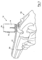
- Figure 1 is a perspective view showing an alignment device embodying the invention together with a fitting guide;
- Figure 2 shows a front view of the alignment device disassembled into its two component parts, and also shows a plan view of the fitting guide;
- Figure 3 gives a perspective view of the alignment device fitted onto the barrel(s) of a firearm;
- Figure 4 is a side view of the view shown in Figure 3 in which both the alignment device and the fitting guide may be seen;
- Figure 5 is a plan view of Figure 4;
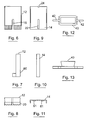
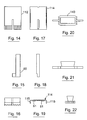
- Figures 6, 7 and 8 show respectively a front view, a side view and a plan view of a first component part of the alignment device;
- Figures 9, 10 and 11 show respectively a front view, a side view and a plan view of a second component part of the alignment device;
- Figures 12, and 13 show respectively a plan view and a side view of the fitting guide;
- Figures 14, 15 and 16 show respectively a front view, a side view and a plan view of an alternative embodiment of the first component of the alignment device; and
- Figures 17, 18 and 19 show respectively a front view, a side view and a plan view of an alternative embodiment of the second component of the alignment device; and
- Figures 20, 21 and 22 show respectively a plan view, a side view and an end view of an embodiment of the fitting guide;
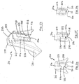
- Figure 23 shows a perspective view of a third embodiment of an alignment device embodying the invention;
- Figure 24 shows the device of Figure 23 mounted on "side-by-side gun barrels;
- Figure 25 shows part of the device of Figure 24 in a first mode of use; and
- Figure 26 shows part of the device of Figure 24 in a second mode of use.
-
- Referring now to the drawings, an alignment device embodying the invention is generally indicated as 10.
- The
alignment device 10 comprises a first component part in the form of abody 12 and a second component part in the form of acover 14. In Figures 14 to 19, the body and the cover are enumerated as 112 and 114 respectively. It will be seen that thebody 112 and thecover 114 are generally similar to thebody 12 and thecover 14 and the following descriptions apply, in the main, to both embodiments. - The
body 12 is shaped to define anelongate aperture 16 which extends to, or substantially to, abase side 18 of the body. In the preferred embodiment, theaperture 16 is formed fully to the base side 18 (i.e. is open-ended) and thus comprises an elongate incision or recess. Thebody 12 further comprises a pair offeet 20 which project substantially perpendicularly from thebase 18 of thebody 12. It will be understood that thebody 12 need not comprise exactly twofeet 20. It is preferred, but is not essential, that the body be generally rectangular in cross-sectional shape. - The
cover 14 is shaped and dimensioned to fit slidably onto thebody 12 and may be referred to as a slide. To this end, as may best be seen from Figures 11 and 19, thecover 14 has a substantially U-shaped or C-shaped transverse cross-section. In particular, it will be seen from Figures 8 and 11, that thecover 14 may be shaped in transverse cross-section to define a mortis while thebody 12 may be shaped in transverse cross-section to define a corresponding tenon.
Alternatively, it will be seen from Figures 16 and 19 that thebody 112 may alternatively be substantially rectangular in transverse cross-section while thecover 114 comprises substantially L-shapedside portions 115 shaped and dimensioned to embrace thebody 112 during use. In either case, the arrangement is such that thecover 14 may be slidably mounted on thebody 12 and be capable of sliding movement back and forth in a direction which is substantially parallel to the longitudinal axis of theelongate aperture 16. - The
cover 14 is shaped to define a firstelongate aperture 22 and a second smaller aperture preferably in the form of a notch orrecess 24. Theelongate aperture 22 extends substantially to, but preferably does not intersect with, afirst edge 26 of thecover 14. The second aperture or notch 24 is preferably formed at or adjacent asecond edge 28 of thecover 14, thesecond edge 28 advantageously being opposite to thefirst edge 26. In the preferred embodiment, thenotch 24 is formed in or at the second edge. Thenotch 24 is located substantially on the longitudinal axis of thefirst aperture 22. - The arrangement is such that, depending how the
cover 14 is fitted onto thebody 12, either thefirst aperture 22 or thenotch 24 can be in alignment with theaperture 16 formed on thebody 12. For example, should thecover 14 be fitted to thebody 12 such that thefirst edge 26 of thecover 14 is closest to thebase side 18 of thebody 12, then the elongatefirst aperture 22 of thecover 14 can be positioned at least partially in register with theaperture 16 of thebody 12. This may be referred to as a first mode of operation and is illustrated in Figure 3. - In a second mode of operation the
cover 14 is fitted to thebody 12 in an inverse manner such that thesecond edge 28 of thecover 14 is closest to thebase side 18 of thebody 12 and that thenotch 24 can be brought into register with theaperture 16. - When using the
alignment device 10 to fit a firearm to the user, either the first or second mode of operation is used depending on which type of aiming alignment is desired by the user. The first mode of operation is typically used where a user wishes to "shoot high" (sometimes referred to as using a "high stock"), while the second mode of operation may be used when the user wishes to "shoot flat" (sometimes referred to as using a "flat stock" or "low stock"), as is explained in more detail below. - The
device 10 is adapted to be mounted on the, in use, upper surface of one ormore barrels 50 of afirearm 52. To this end, it is preferred that at least thebase 18 of thebody 12 is formed from a magnetic material so that it may retain a set position on the gun barrel(s) 50. Typically, the upper surface of the barrel(s) 50 is provided by arib 51 that runs along the top of the barrel(s) 50. As can be seen from Figures 3, 4 and 5, thealignment device 10 is positioned at or adjacent the butt, or breech, end of the barrel(s) 50 distal a sighting bead (not shown), or other sighting component (sometimes referred to as the "foresight") which is centrally located on top of the barrel(s) 50 at the firing end of the barrel(s) 50. The invention is particularly suited for use with shotguns (as depicted in the drawings) typically having two barrel(s) 50 either in an "over-and-under" arrangement as depicted in the drawings or in a "side-by-side" arrangement (not illustrated). In either case arib 51 is normally centrally located on top of the barrel(s) 50. In such cases, thedevice 10 is placed on therib 51 and the user's line of sight is along therib 51. - The
device 10 should be mounted on the barrel(s) 50 (on therib 51 where applicable) such that theaperture 16 is substantially aligned with the sighting bead along the line of sight of the barrel(s), i.e. substantially along the central longitudinal axis of the barrel(s) 50 (usually along the rib 51). To this end, it is advantageous to use afitting guide 40 to help mount thealignment device 10 onto thefirearm 52. Thefitting guide 40 has at least oneelongate portion 42, which may be aligned by a user with the central longitudinal axis of the barrel(s) 50. In the illustrated embodiment, thefitting guide 40 includes twoelongate portions 42 projecting in opposite directions from opposite sides of agrip 44. At least one of theelongate portions 42 is preferably shaped and dimensioned to fit through theaperture 16 formed in thebody 12. Thefitting guide 40 also includes inter-engaging members in the form ofteeth 46 adjacent to the base of theelongate member 42. Corresponding teeth 21 are preferably provided on the ends of thefeet 20 of thebody 12. In use, the user first positions thefitting guide 40 on the gun barrel(s) 50 and then positions thealignment device 10 onto the barrel(s) 50 such that therespective teeth 21, 46 of thebody 12 and thefitting guide 40 inter-engage (see Figure 5). Thefitting guide 40 is then removed. It is noted that for many shotguns - particularly those of the "over-and-under" type with a wide rib, or "side-by-side" type - thefitting guide 40 is not required as thedevice 10 can readily be aligned with the rib itself or with the breech of the shotgun. - If the user wishes to "shoot flat", then when the
firearm 52 is correctly held by the user, the user's eye should be substantially level with the top of the barrel(s)s 50 and the user should be looking directly down the centre of the barrel(s) 50 at the sighting bead. If thefirearm 52 is a poor fit to the user, the user's eye will be too high or too low and in which case the "drop" of thefirearm 52 is misaligned. This may mean that the butt of thefirearm 52 has to be cut away or built up, as appropriate, to rectify the misalignment. Alternatively, or additionally, the user's eye may be too far left or too far right with respect to the barrel(s) 50 so that the user is not looking directly down the centre of the barrel(s).
This means that the "cast" of thefirearm 52 requires adjustment. The cast can be altered by building up the sides of the butt, or by bending the butt from side to side. By using thealignment device 10 in the second mode of operation, the user may readily determine whether or not thefirearm 52 fits the user in order that he may "shoot flat" and, if not, may subsequently be used to check whether any subsequent modifications to the gun have rectified the misalignment. This is explained in more detail below. - In the second mode of operation, the
cover 14 is positioned on the body so that thenotch 24 is located at, or substantially at, thebase side 18 of thebody 12. In this position, most of theaperture 16 and thebody 12 is obscured by the cover, save for a relatively small portion of theaperture 16 which is exposed by thenotch 24. This exposed portion is at or adjacent thebase side 18 of thebody 12. Hence, thealignment device 10 provides a bead-sighting aperture (i.e. the portion ofaperture 16 exposed by notch 24) located adjacent, or substantially at, the level of the surface of the gun barrel(s) 50 (usually the in use upper surface of the rib 51). In the preferred embodiment where theaperture 16 and thenotch 24 are both open-ended, the framing aperture is also open-ended and opens onto the top of the barrel(s) 50, or onto therib 51, when mounted as described above. It may be seen from Figure 26 (which shows analternative embodiment 210 in the second mode of operation) that thenotch 224 is located adjacent, or immediately above, the in use upper surface of the barrel(s) 50 (as provided by the rib 51). The arrangement is such that the bead may be viewed by looking through thenotch notch 24, 224 (or more particularly the bead-sighting aperture defined by the overlap between thenotch aperture 16, 216) to the bead is substantially parallel with and, advantageously substantially coincident with, the in use upper surface of the barrel(s) 50 (or rib 51). - Further, with the
alignment device 10 mounted to thefirearm 52 as described above, the exposed aperture is substantially centrally located on top of the barrel(s) 50. Still further, the relative dimensions of thenotch 24 and/or theaperture 16 are such that a user may view the sighting bead through the exposed aperture, but that the sighting bead substantially fills the exposed aperture. Clearly this will depend on the length of the barrel(s) and the size of the sighting bead. - Hence, when the user holds the
firearm 52 in what he considers to be the "shooting flat" position, if thefirearm 52 fits the user properly, then the sighting bead will be framed in the exposed sighting aperture provided by the alignment device 10 (and will, in the preferred embodiment, substantially fill the user's view through the exposed aperture). If the sighting bead is not visible, or is only partially visible, to the user through thealignment device 10, then thefirearm 52 requires adjustment. - If a user wishes to shoot high, this means that the line of sight from the user's eye (when holding a firearm in a use position) to the sighting bead is inclined with respect to the gun barrel(s) in a vertical plane i.e. the user is looking downwardly at the sighting bead as opposed to looking directly along the barrel(s). The result of this is that when the user lines up the sighting bead with the target, the barrel(s) 50 are actually inclined upwardly and so the firearm will shoot higher than the point at which the user is aiming. This can be advantageous when shooting at targets which move upwardly, e.g. clay pigeon shooting - the user can aim at the target but will actually shoot higher than the target thereby compensating for the upward movement of the target.
- In both the first and second modes of operation, the
alignment device 10 may be used to check whether or not thefirearm 52 fits a user who wishes to shoot high.
In the second mode of operation, the user slides thecover 14 with respect to thebody 12 in an, in use, upwardly direction thereby adjusting the location of thenotch 24 with respect to theaperture 16. The amount by which the user slides thecover 14 depends on the amount by which the user wishes to shoot high.
This time, when the user holds thefirearm 52 in the firing position, the sighting bead should be framed in the end of the exposedaperture 16 defined by thenotch 24. If not, then thefirearm 52 does not fit the user correctly to shoot high by the desired amount and/or may require lateral adjustment. - In the first mode of operation, the
aperture 22 of thecover 14 is at least partly in register with theaperture 16 of thebody 12. The exposed aperture defined by the overlap betweenapertures aperture 16 and at the other end by the end ofaperture 22 as defined bycrosspiece 23. In this mode of operation, if thefirearm 52 fits the user correctly, then the sighting bead will be framed in the exposed aperture just above thecrosspiece 23. The first mode of operation is preferred since the exposed aperture allows the user to see beyond the bead. - In preferred embodiments a respective face of each of the
body 12 and of thecover 14, which respective faces engage when thecover 14 is fitted to thebody 12, are provided with a respective set of inter-engaging teeth, so that thecover 14 and thebody 12 may adopt one of a plurality of discrete positions with respect to one another, each discrete relative position being held by inter-engagement of the respective teeth. This is illustrated by way of example in Figures 7 and 11 and in Figures 15 and 19 where the respective sets of inter-engagable teeth are enumerated as 60 and 61 respectively. - Figure 23 shows a third embodiment of an alignment device, generally indicated as 210. The
device 210 may be generally similar to thedevice 10 and so similar descriptions apply and similar numerals are used to indicate like parts. - The
device 210 comprises abody 212 and acover 214. Thebody 212 includes an elongate aperture, or slot, 216 similar to theaperture 16 inbody 12. Thecover 214 includes an elongate aperture, or slot, 222 and a smaller aperture, preferably anotch 224, that are generally similar toaperture 22 and notch 24 respectively. In the preferred embodiment, thenotch 224 is aligned generally with the longitudinal axis of theaperture 222 and is located adjacent theaperture 222. Thecross piece 223 is located between theaperture 222 and thenotch 224. The cover is advantageously slidable with respect to the body in a direction generally parallel with the longitudinal axis of theelongate aperture 222. To this end, thebody 212 may be shaped to define aseat 225 in which thecover 214 may be slidably received. When mounted on thebody 212, theaperture 222 of thecover 214 may be adjusted so that it is at least partially in register with theaperture 216 in thebody 212. Ascrew 227, or other conventional fixing device, is provided for fixing the position of thecover 214 with respect to thebody 212. - In the preferred embodiment, the
body 212 is supported by a mounting frame 229 which, in use, mounts thedevice 210 on the barrel(s) 50 of a firearm. Figure 24 shows thedevice 210 mounted on twobarrels 50 in a side-by-side arrangement, although thedevice 210 may equally be mounted on a single barrel or on top of two barrels in an over-and-under arrangement. The mounting frame 229 comprises arespective leg 231 on either side of thebody 212, whichlegs 231 are shaped to be seated on top of a respective barrel of an over-and-under type barrel arrangement. The arrangement is such that, when the mounting frame 229 is seated on thebarrels 50, thebody 212, and more particularly theelongate apertures body 212 is magnetised, or includes one or more magnets (not shown) at itsbase 218, i.e. on one or both sides of theaperture 216. - Advantageously, the
body 212 is slidably mounted in the frame 229 in a direction generally parallel with the longitudinal axis of theelongate aperture 216. To this end, thebody 212 may be shaped to define aseat 233 in which thebody 212 may be slidably received. This facilitates mounting thedevice 210 on a firearm and accommodates barrels of different shapes and dimensions. - In the preferred embodiment, the
cover 214 includes one ormore markings 235 which may be matched against markings 237 provided on thebody 212 in order to record the relative position of thecover 214 with respect to thebody 212.
In the preferred embodiment, the second edge 228 of thecover 214 is convex in order to generally match the shape ofribs 51 that have a concave upper surface. - Figure 24 shows the device 210 (without the mounting frame 229) in the first mode of use. The firearm is not shown in Figure 24 but the bead, or foresight, is represented at 239. It is assumed, for the purposes of example, that the relative position of the
cover 214 with respect to thebody 212 has been set by a user (not shown) to suit his needs. When thedevice 210 is subsequently fitted to a firearm, thedevice 210 may be used to determine if the firearm requires adjustment. In Figure 24, thebead 239 is visible through the overlapping portion ofapertures cross piece 223. Hence, the "drop" of the firearm is deemed to be correct. If thebead 223 appears higher or lower than the cross piece, then the "drop" of the firearm requires adjustment. Moreover, in Figure 24, thebead 239 is approximately centrally located in theapertures 216, 222 (in a direction perpendicular with the longitudinal axis of theapertures 216, 222). This is an indication that the "cast" of the firearm is correct. If thebead 239 were to appear to the left or the right of the longitudinal axis of theapertures device set device - In Figure 25, the
device 210 is shown (without the mounting frame 229) in the second mode of operation. Thecover 214 is positioned with respect to thebody 212 such that thenotch 224 is located substantially at thebase side 218 of thebody 212. Hence, thedevice 210 defines a sighting aperture (by the overlap ofnotch 224 with aperture 216) substantially at the base of thedevice 210. In the preferred embodiment, the sighting aperture is open-ended, i.e. notch-like, and so opens onto, when fitted to a firearm, the barrel(s) of the firearm. It will be seen from Figure 25 that thecover 214, and therefore the sighting aperture, is spaced-apart from therib 51, although thecover 214 may alternatively be in contact with therib 51 in this mode of use. In Figure 25, thebead 239 is framed in the sighting aperture. This indicates that the firearm fits the user correctly for "shooting flat". - The
device device device - The invention is not limited to the embodiments described therein which may be modified without departing from the scope of the invention.
Claims (13)
- An alignment device for a firearm, the alignment device being mountable on said firearm and being shaped to define, in at least one mode of use, a sighting aperture located adjacent a base of the device such that, when the base is positioned, in use, on a surface of the firearm, the sighting aperture is located adjacent said surface.
- An alignment device as claimed in Claim 1, wherein said sighting aperture is open-ended such that, when fitted to said surface, the sighting aperture opens onto said surface.
- An alignment device as claimed in Claim 1 or 2, wherein the device comprises a body shaped to define elongate aperture having a longitudinal axis extending in a first direction; and a cover mountable on the body and including at least one aperture that is at least partially in register with said elongate aperture during use, the body and the cover being movable with respect to one another substantially in said first direction.
- An alignment device as claimed in Claim 3, wherein said elongate aperture is open-ended, opening onto the base of the device.
- An alignment device as claimed in Claim 3 or 4, wherein said cover includes a notch formed in an edge of the cover and, when the cover is mounted on the body in at least one mode of use, the edge is located substantially at the base of the device.
- An alignment device as claimed in Claim 5, wherein said notch is located substantially in register with the open end of said elongate aperture.
- An alignment device as claimed in any one of Claims 3 to 6, wherein said cover includes first and second apertures, each of said first and second apertures being located substantially in register with the longitudinal axis of the elongate aperture when the cover is mounted on the body.
- An alignment device as claimed in Claim 7 when dependent on Claim 5 or 6, wherein said first aperture comprises said notch and said second aperture comprises an elongate aperture extending substantially in said first direction.
- An alignment device as claimed in any one of Claims 3 to 8, wherein said at least one aperture of the cover terminates in a cross piece, the cross piece obscuring part of said elongate aperture when the cover is mounted on the body in at least one mode of use.
- An alignment device as claimed in Claim 9, wherein said first aperture is located substantially at one edge of the cover, the second aperture being located adjacent the opposite edge of the cover, said cross piece being defined between said second aperture and said opposite edge.
- An alignment device as claimed in Claim 9, wherein said cross piece is defined between the first and second apertures.
- An alignment device as claimed in any preceding claim, wherein the device is mountable in a frame, the frame being mountable on at least one barrel of a firearm, the device being slidable with respect to the frame generally in said first direction.
- An alignment device for a firearm comprising at least one barrel, the alignment device being mountable on said at least one barrel and being shaped to define a sighting aperture, wherein the device comprises a body shaped to define elongate aperture having a longitudinal axis extending in a first direction; and a cover mountable on the body and including an elongate aperture having a longitudinal axis extending in said first direction and being at least partially in register with said elongate aperture of the body when the cover is mounted on the body in at least one mode of use, the body and the cover being movable with respect to one another substantially in said first direction, the sighting aperture being defined by the overlap between the respective elongate apertures of the cover and the body.
Applications Claiming Priority (2)
| Application Number | Priority Date | Filing Date | Title |
|---|---|---|---|
| GB0320153 | 2003-08-28 | ||
| GBGB0320153.0A GB0320153D0 (en) | 2003-08-28 | 2003-08-28 | An alignment device for a firearm |
Publications (1)
| Publication Number | Publication Date |
|---|---|
| EP1510774A1 true EP1510774A1 (en) | 2005-03-02 |
Family
ID=28686477
Family Applications (1)
| Application Number | Title | Priority Date | Filing Date |
|---|---|---|---|
| EP04020340A Withdrawn EP1510774A1 (en) | 2003-08-28 | 2004-08-27 | An alignment device for a firearm |
Country Status (3)
| Country | Link |
|---|---|
| US (1) | US20050072035A1 (en) |
| EP (1) | EP1510774A1 (en) |
| GB (1) | GB0320153D0 (en) |
Cited By (1)
| Publication number | Priority date | Publication date | Assignee | Title |
|---|---|---|---|---|
| WO2009012777A1 (en) * | 2007-07-26 | 2009-01-29 | Iversen, Torben | Adjusting device for a shotgun |
Families Citing this family (4)
| Publication number | Priority date | Publication date | Assignee | Title |
|---|---|---|---|---|
| US7377068B2 (en) * | 2005-10-12 | 2008-05-27 | Musser Stephen R | Method and apparatus for fitting and aiming a firearm |
| US7644531B2 (en) * | 2007-08-14 | 2010-01-12 | Musser Stephen R | Method and apparatus for fitting and aiming a firearm |
| US8196333B2 (en) * | 2010-04-07 | 2012-06-12 | Sig Sauer, Inc. | Rail mountable diopter rear sight |
| US10082364B2 (en) * | 2015-11-10 | 2018-09-25 | Lanny Dale Hinson, JR. | Shotgun fitter |
Citations (3)
| Publication number | Priority date | Publication date | Assignee | Title |
|---|---|---|---|---|
| GB191225381A (en) * | 1911-12-28 | 1913-07-03 | Edward James Dunn Newitt | Improvements in or relating to Gun-sights. |
| GB191223109A (en) * | 1912-01-11 | 1913-07-10 | James Wallace | Improvements in Back-sights for Rifles and other Small Arms. |
| GB168264A (en) * | 1920-10-13 | 1921-09-01 | Hugh Reginald Hearson | Improvements in aperture sights for rifles |
Family Cites Families (1)
| Publication number | Priority date | Publication date | Assignee | Title |
|---|---|---|---|---|
| US4976038A (en) * | 1989-08-07 | 1990-12-11 | Nattrass Floyd C | Shotgun sighting system and method |
-
2003
- 2003-08-28 GB GBGB0320153.0A patent/GB0320153D0/en not_active Ceased
-
2004
- 2004-08-27 US US10/928,588 patent/US20050072035A1/en not_active Abandoned
- 2004-08-27 EP EP04020340A patent/EP1510774A1/en not_active Withdrawn
Patent Citations (3)
| Publication number | Priority date | Publication date | Assignee | Title |
|---|---|---|---|---|
| GB191225381A (en) * | 1911-12-28 | 1913-07-03 | Edward James Dunn Newitt | Improvements in or relating to Gun-sights. |
| GB191223109A (en) * | 1912-01-11 | 1913-07-10 | James Wallace | Improvements in Back-sights for Rifles and other Small Arms. |
| GB168264A (en) * | 1920-10-13 | 1921-09-01 | Hugh Reginald Hearson | Improvements in aperture sights for rifles |
Cited By (1)
| Publication number | Priority date | Publication date | Assignee | Title |
|---|---|---|---|---|
| WO2009012777A1 (en) * | 2007-07-26 | 2009-01-29 | Iversen, Torben | Adjusting device for a shotgun |
Also Published As
| Publication number | Publication date |
|---|---|
| GB0320153D0 (en) | 2003-10-01 |
| US20050072035A1 (en) | 2005-04-07 |
Similar Documents
| Publication | Publication Date | Title |
|---|---|---|
| US9506726B2 (en) | Accessory mounting system for firearms | |
| US6813855B2 (en) | Gun sight reticle alignment | |
| US5442860A (en) | Portable reticle alingment device for firearms | |
| US8667727B2 (en) | Device for mounting an additional device to a firearm | |
| US7726229B2 (en) | Rotatable and retractable rear gun sight | |
| US8196332B2 (en) | Forward scout scope mount for firearm | |
| US7913439B2 (en) | Accessory mount | |
| US11796264B2 (en) | Slide assembly for a firearm | |
| US9863740B2 (en) | Magnetically stabilized firearm sight | |
| US8245433B1 (en) | Apparatus for maintaining proper orientation of an aiming eye when firing a shotgun | |
| US6058616A (en) | Sighting device for small arms | |
| US4509282A (en) | Sight and scope conversion mounting | |
| US20120131838A1 (en) | Adaptive Rail System for AK-Style Weapon | |
| US20030140544A1 (en) | Shotgun sighting device | |
| US11131526B2 (en) | Handgun slide with embedded sight assembly | |
| US20160123697A1 (en) | Easy Alignment Stock | |
| US9464868B2 (en) | Shooting aid | |
| US10254081B2 (en) | Weapon sight | |
| US5481818A (en) | Gun sight mounting system | |
| US20100275498A1 (en) | Reduced eye relief, co-witnessing sight mount | |
| EP1510774A1 (en) | An alignment device for a firearm | |
| WO2014159397A1 (en) | Rubber band mounted reticle leveling device for use in leveling telescopic rifle sight | |
| CA1122837A (en) | Platform ramp sight for firearms | |
| US20130219766A1 (en) | Method for Replacing Weapon Rear Sight with Optics | |
| US4244114A (en) | Stepped platform ramp sight for firearms |
Legal Events
| Date | Code | Title | Description |
|---|---|---|---|
| PUAI | Public reference made under article 153(3) epc to a published international application that has entered the european phase |
Free format text: ORIGINAL CODE: 0009012 |
|
| AK | Designated contracting states |
Kind code of ref document: A1 Designated state(s): AT BE BG CH CY CZ DE DK EE ES FI FR GB GR HU IE IT LI LU MC NL PL PT RO SE SI SK TR |
|
| AX | Request for extension of the european patent |
Extension state: AL HR LT LV MK |
|
| AKX | Designation fees paid | ||
| REG | Reference to a national code |
Ref country code: DE Ref legal event code: 8566 |
|
| STAA | Information on the status of an ep patent application or granted ep patent |
Free format text: STATUS: THE APPLICATION IS DEEMED TO BE WITHDRAWN |
|
| 18D | Application deemed to be withdrawn |
Effective date: 20050903 |