EP1510740B1 - Mischventil - Google Patents
Mischventil Download PDFInfo
- Publication number
- EP1510740B1 EP1510740B1 EP20040462006 EP04462006A EP1510740B1 EP 1510740 B1 EP1510740 B1 EP 1510740B1 EP 20040462006 EP20040462006 EP 20040462006 EP 04462006 A EP04462006 A EP 04462006A EP 1510740 B1 EP1510740 B1 EP 1510740B1
- Authority
- EP
- European Patent Office
- Prior art keywords
- cartridge
- moving element
- control disc
- disc
- ceramic moving
- Prior art date
- Legal status (The legal status is an assumption and is not a legal conclusion. Google has not performed a legal analysis and makes no representation as to the accuracy of the status listed.)
- Expired - Lifetime
Links
- 239000000919 ceramic Substances 0.000 claims description 38
- XLYOFNOQVPJJNP-UHFFFAOYSA-N water Substances O XLYOFNOQVPJJNP-UHFFFAOYSA-N 0.000 claims description 13
- 238000007789 sealing Methods 0.000 description 3
- 230000000694 effects Effects 0.000 description 2
- 230000001276 controlling effect Effects 0.000 description 1
- 230000002349 favourable effect Effects 0.000 description 1
- 239000000463 material Substances 0.000 description 1
- 230000001105 regulatory effect Effects 0.000 description 1
Images



Classifications
-
- F—MECHANICAL ENGINEERING; LIGHTING; HEATING; WEAPONS; BLASTING
- F16—ENGINEERING ELEMENTS AND UNITS; GENERAL MEASURES FOR PRODUCING AND MAINTAINING EFFECTIVE FUNCTIONING OF MACHINES OR INSTALLATIONS; THERMAL INSULATION IN GENERAL
- F16K—VALVES; TAPS; COCKS; ACTUATING-FLOATS; DEVICES FOR VENTING OR AERATING
- F16K11/00—Multiple-way valves, e.g. mixing valves; Pipe fittings incorporating such valves
- F16K11/02—Multiple-way valves, e.g. mixing valves; Pipe fittings incorporating such valves with all movable sealing faces moving as one unit
- F16K11/06—Multiple-way valves, e.g. mixing valves; Pipe fittings incorporating such valves with all movable sealing faces moving as one unit comprising only sliding valves, i.e. sliding closure elements
- F16K11/078—Multiple-way valves, e.g. mixing valves; Pipe fittings incorporating such valves with all movable sealing faces moving as one unit comprising only sliding valves, i.e. sliding closure elements with pivoted and linearly movable closure members
-
- Y—GENERAL TAGGING OF NEW TECHNOLOGICAL DEVELOPMENTS; GENERAL TAGGING OF CROSS-SECTIONAL TECHNOLOGIES SPANNING OVER SEVERAL SECTIONS OF THE IPC; TECHNICAL SUBJECTS COVERED BY FORMER USPC CROSS-REFERENCE ART COLLECTIONS [XRACs] AND DIGESTS
- Y10—TECHNICAL SUBJECTS COVERED BY FORMER USPC
- Y10T—TECHNICAL SUBJECTS COVERED BY FORMER US CLASSIFICATION
- Y10T137/00—Fluid handling
- Y10T137/8593—Systems
- Y10T137/86493—Multi-way valve unit
- Y10T137/86549—Selective reciprocation or rotation
-
- Y—GENERAL TAGGING OF NEW TECHNOLOGICAL DEVELOPMENTS; GENERAL TAGGING OF CROSS-SECTIONAL TECHNOLOGIES SPANNING OVER SEVERAL SECTIONS OF THE IPC; TECHNICAL SUBJECTS COVERED BY FORMER USPC CROSS-REFERENCE ART COLLECTIONS [XRACs] AND DIGESTS
- Y10—TECHNICAL SUBJECTS COVERED BY FORMER USPC
- Y10T—TECHNICAL SUBJECTS COVERED BY FORMER US CLASSIFICATION
- Y10T137/00—Fluid handling
- Y10T137/8593—Systems
- Y10T137/86493—Multi-way valve unit
- Y10T137/86815—Multiple inlet with single outlet
-
- Y—GENERAL TAGGING OF NEW TECHNOLOGICAL DEVELOPMENTS; GENERAL TAGGING OF CROSS-SECTIONAL TECHNOLOGIES SPANNING OVER SEVERAL SECTIONS OF THE IPC; TECHNICAL SUBJECTS COVERED BY FORMER USPC CROSS-REFERENCE ART COLLECTIONS [XRACs] AND DIGESTS
- Y10—TECHNICAL SUBJECTS COVERED BY FORMER USPC
- Y10T—TECHNICAL SUBJECTS COVERED BY FORMER US CLASSIFICATION
- Y10T137/00—Fluid handling
- Y10T137/8593—Systems
- Y10T137/86493—Multi-way valve unit
- Y10T137/86815—Multiple inlet with single outlet
- Y10T137/86823—Rotary valve
Definitions
- the invention relates to a mixing valve cartridge used mainly for mixing cold and hot water, preferably a universal mixing valve cartridge with plane discs.
- Cartridges are essentially valve inserts which realize in one single structural unit the closing of the cold and hot water pipes, their opening when necessary, the mixing of the cold and hot water, and directing of the mixed water to the outlet.
- the cartridges comprise a housing closed up by a bottom plate, and inside this housing, an inlet disc one side of which is connected to the bottom plate, whereas its other side is coupled to a rotable and movable control disc.
- the movement of the control disc is ensured by a bearing supported by a lever being in a lever holder through a ceramic element.
- the lever holder is arranged in the housing of the cartridge so that it is rotatable.
- Appropriate bores and cavities are situated in both the inlet disc and the control disc for controlling the flow of the cold and hot water, and the outflow of the mixed water.
- the aim of the cartridge according to the invention is to provide a novel design of the control disc and the ceramic moving element in the cartridge by means of which the tolerance regarding the pressure inserted on the elements, i.e. the pressure resistance of the cartridges increases in both opened and closed position, when the outlet is pushed.
- Figure 1 shows a generally used arrangement of the ceramic moving element K and control disc SZ in a cartridge.
- Figure 1 illustrates a ceramic moving element K coupled to a control disc SZ.
- a groove H is situated, into which a gasket T of the form of an annulus is placed protruding a little from groove H and bears up against control disc SZ ensuring here an appropriate seal between the ceramic moving element K and the control disc SZ.
- a slot y is to be found lying in the direction of the axis of the cartridge, mainly it is needed for technological reason for avoiding the overdetermination of the arrangement of the elements.
- the disadvantage of this solution is that as the pressure increases (and in certain cases it could be quite large), the slot y inside the cartridge between the ceramic moving element K and the control disc SZ increases, gasket T will expand so that it may eventually be even blown out.
- the object of the invention is to produce an arrangement in which the position of the elements remains stable, i.e. the slot between the ceramic moving element and the control disc does not change at all, or only to a small extent, and at the same time, the gasket is situated so that its lifetime significantly increases due to its smaller deformation under pressure.
- the invention relates to a mixing valve cartridge used mainly for mixing cold and hot water, in the housing of which two superimposed discs forming a plane seal with each other are to be found, one of them is a fixed inlet disc, the other one a control disc situated at one side of the inlet disc so that it is rotatable and movable, the control disc is in a driving connection with a lever provided with a bearing and situated in a lever holder via a ceramic moving element, the lever holder can be rotated in the housing of the cartridge.
- a bottom plate provided with inlet bores and forming the bottom of the housing of the cartridge is positioned, one side of which is in connection with the inlet disc, whereas the other one is developed so that it can be connected to connection ducts, in the moving element a groove with a gasket in it is provided.
- the essence of the invention consists in that the ceramic moving element has a side facing the control disc that includes an annular stepped part parallel to the axis of the cartridge housing and is connected to the groove, and the control disc has an annular stepped part fitting the annular stepped part of the ceramic moving element, and between the annular stepped parts a radial slot is maintained, which remains unchanged also during operation.
- the stepped parts have vertical walls being parallel to the axis of the cartridge and horizontal walls being perpendicular to the vertical walls.
- Figure 1 shows, as it was mentioned in the introductory part, the lateral section of the arrangement of the ceramic moving element K and control disc SZ in a cartridge used according to the prior art for mixing of cold and hot water. Only those elements are shown in Fig. 1 , which are developed differently according to the invention as in the usual solutions, or their bearing force is different.
- Fig. 1 ceramic moving element K and control disc SZ are superimposed forming a flat plane so that in the surface of ceramic moving element K to the side of control disc SZ a groove H is developed, provided with a gasket T which has to be pressure-resistant in order to resist the pressure P in the cartridge during use. It is also seen in Fig. 1 that parallel to the axis of the cartridge, between ceramic moving element K and control disc SZ, a slot y is to be found into which gasket T reaches. When a pressure P develops, as an effect of this, ceramic moving element K and control disc SZ move away from each other, the material of gasket T becomes deformed, in certain cases it may also be ruined or blow up, making thereby the whole cartridge unusable.
- the aim of the invention is to solve this problem.
- gasket T is placed so that its deformation effected by the pressure is less, than usual and, at the same time, ceramic moving element K and control disc SZ are arranged so that their position to each other does not change, a more reliable cartridge with a longer function time can be obtained.
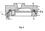
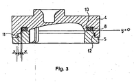
- Figures 2 and 3 show the arrangement of ceramic moving element 4 and control disc 5 in the cartridge according to the invention in a lateral section, at mounting and in operation.
- Figures 2 and 3 illustrate the arrangement and an embodiment used as an example of ceramic moving element 4 and control disc 5.
- a groove 10 in which a gasket 8 is arranged.
- Ceramic moving element 4 and control disc 5 are developed so that at the part where gasket 8 is placed, in both elements stepped parts 11 and 12 are formed fitting to each other, but between them a radial slot x perpendicular to the axis of the cartridge is to be found.
- pressure P develops, due to the increase of pressure, the radial surfaces of the stepped parts 11 and 12 adjoin each other, however, as a result of this movement, the size of slot x does not change. It can be observed well in Fig.
- Figures 4a and 4b show the lateral section and top view of ceramic moving element 4, whereas in Figs 5a and 5b those of control disc 5 are illustrated for one embodiment each.
- Fig 5b shows that stepped part 12 extends around the circumference of the control disc 5. The same refers to stepped part 11.Thus the space between the stepped parts 11 and 12 shows annular features.
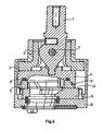
- Figure 6 shows the main section of the cartridge according to the invention in its mounted position.
- a lever holder 2 is also shown, in which lever 1 is supported by a bearing around a rotation axis 7 that is in a driving connection with control disc 5 via ceramic moving element 4 and is situated at one side of control disc 5.
- an inlet disc 6 is arranged having cavities for introducing cold and hot water and letting out the mixed water.
- inlet disc 6 is connected to control disc 5, whereas other side of the inlet disc 6 in connection with one side of bottom plate 9 forming the bottom of housing 3.
- seals are placed as known from the prior art.
- the cavities in the inlet disc 6 can be closed or bridged over by control disc 5, thereby the amount and temperature of the mixed water flowing out through the cavities in bottom plate 9 into cartridge body can be regulated.
- the invention eliminates the increase of slot x to be sealed by a gasket in function of pressure.
- the fact that slot x is positioned in a direction perpendicular to the direction of pressure is also favourable from the viewpoint of good sealing.
- the advantage of the cartridge according to the invention is that by developing the stepped parts in ceramic moving element 4 and control disc 5, the durability of the seal between ceramic moving element 4 and control disc 5, and thereby that of the whole cartridge increases.
Landscapes
- Engineering & Computer Science (AREA)
- General Engineering & Computer Science (AREA)
- Mechanical Engineering (AREA)
- Multiple-Way Valves (AREA)
- Domestic Plumbing Installations (AREA)
Claims (2)
- Mischventilkartusche, die hauptsächlich zum Mischen von Kalt- und Warmwasser verwendet wird, enthaltend in dem Gehäuse (3) der Kartusche zwei übereinander angeordnete miteinander eine Flachdichtung bildende Scheiben (5, 6), eine befestigte Einlassscheibe (6) und eine Steuerscheibe (5), die auf einer Seite der Einlassscheibe (6) auf bewegbare und drehbare Weise angeordnet ist, die Steuerscheibe (5) mit einem durch ein in einem Hebelhalter (2) gehaltenes Lager gestützten Hebel (1) über ein keramisches Bewegungselement (4) in Antriebsverbindung steht, wobei der Hebelhalter in dem Gehäuse (3) der Kartusche in einer drehbaren Position angeordnet ist, auf der anderen Seite der Einlassscheibe (6) eine untere Platte (9) angeordnet ist, die mit Einlassöffnungen versehen ist, und den unteren Teil des Gehäuses (3) bildet, eine Seite der unteren Platte (9) an der Einlassscheibe (6) angeschlossen ist, während ihre andere Seite auf die Weise ausgebildet ist, dass sie an Anschlussleitungen angeschlossen werden kann, in dem keramischen Bewegungselement (4) eine Nut (10) mit einer darin angeordneten Dichtung (8) vorgesehen ist, dadurch gekennzeichnet, dass das keramische Bewegungselement (4) eine zur Steuerscheibe (5) weisende Seite aufweist, die einen ringförmigen gestuften Teil (12) enthält, welcher zu der Achse des Kartuschengehäuses parallel angeordnet ist, und an der Nut (10) angeschlossen ist, weiterhin die Steuerscheibe (5) ein ringförmiges gestuftes Teil (11) aufweist, welches an das ringförmige gestufte Teil (12) des keramischen Bewegungselementes (4) angepasst ist, und zwischen den ringförmigen gestuften Teilen (11, 12) ein radialer Spalt aufrechterhalten ist, welcher auch während des Betriebes unverändert bleibt.
- Kartusche nach Anspruch 1, dadurch gekennzeichnet, dass die gestuften Teile (11, 12) vertikale Wände, die zu der Achse der Kartusche parallel sind, und horizontale Wände, die zu den vertikalen Wänden perpendikulär sind, aufweisen.
Applications Claiming Priority (2)
| Application Number | Priority Date | Filing Date | Title |
|---|---|---|---|
| HU0302813A HU224596B1 (hu) | 2003-09-01 | 2003-09-01 | Csaptelep kartus |
| HU0302813 | 2003-09-01 |
Publications (2)
| Publication Number | Publication Date |
|---|---|
| EP1510740A1 EP1510740A1 (de) | 2005-03-02 |
| EP1510740B1 true EP1510740B1 (de) | 2008-06-11 |
Family
ID=89981612
Family Applications (1)
| Application Number | Title | Priority Date | Filing Date |
|---|---|---|---|
| EP20040462006 Expired - Lifetime EP1510740B1 (de) | 2003-09-01 | 2004-08-24 | Mischventil |
Country Status (7)
| Country | Link |
|---|---|
| US (1) | US7044162B2 (de) |
| EP (1) | EP1510740B1 (de) |
| CN (1) | CN100390452C (de) |
| DE (1) | DE602004014323D1 (de) |
| ES (1) | ES2308132T3 (de) |
| HU (1) | HU224596B1 (de) |
| TW (1) | TWM265500U (de) |
Families Citing this family (11)
| Publication number | Priority date | Publication date | Assignee | Title |
|---|---|---|---|---|
| AU303259S (en) * | 2004-11-15 | 2005-09-20 | Caroma Industries Ltd | A valve cartridge for a waterless urinal |
| ITTO20050068A1 (it) * | 2005-02-08 | 2006-08-09 | Gevipi Ag | Rubinetto con base fissa, perfezionato |
| MX2009007895A (es) * | 2007-01-31 | 2009-07-31 | Moen Inc | Cartucho de valvula insensible a carga de instalacion. |
| US8434513B2 (en) | 2007-01-31 | 2013-05-07 | Moen Incorporated | Valve cartridge with low point of contact for installation |
| US8327882B2 (en) * | 2007-11-15 | 2012-12-11 | Xiamen Lota International Co., Ltd. | Water faucet with joystick cartridge |
| HU230570B1 (hu) * | 2009-12-21 | 2016-12-28 | Kerox Ipari És Kereskedelmi Kft. | Egykaros keverő csaptelep betét megnövelt szögű komfort tartománnyal |
| EP2898242B1 (de) * | 2012-09-24 | 2020-07-22 | Ergonomix Concept E.G Ltd | Nichtlineare übertragungsrate zwischen einem bedienungsgriff und bedientem mechanismus |
| KR101954231B1 (ko) * | 2016-11-17 | 2019-03-05 | 김종구 | 수도밸브카트리지 |
| HUE054522T2 (hu) * | 2019-02-28 | 2021-09-28 | Fluehs Drehtechnik Gmbh | Szelepfelsõrész szaniterszerelvényhez |
| DE102019003301A1 (de) * | 2019-05-10 | 2020-11-12 | Grohe Ag | Einhebel-Kartusche für eine Sanitärarmatur |
| US11781661B1 (en) * | 2022-06-27 | 2023-10-10 | Xiamen Forbetter Sanitary Ware Co., Ltd. | Valve core for faucet |
Family Cites Families (14)
| Publication number | Priority date | Publication date | Assignee | Title |
|---|---|---|---|---|
| IL73930A (en) * | 1984-12-25 | 1988-12-30 | Hamat Koor Metals Ltd | Mixing device for faucets |
| CN1004829B (zh) * | 1985-05-23 | 1989-07-19 | 汉斯格罗(有限无限)股份两合公司 | 卫生设备混水阀控制芯 |
| GB2192256B (en) * | 1986-07-04 | 1990-08-08 | Galatron Srl | Single-control mixing faucet providing the mixing outside the same |
| DE3738854A1 (de) * | 1987-11-16 | 1989-05-24 | Grohe Armaturen Friedrich | Wassermischventil |
| IT1232067B (it) * | 1989-03-31 | 1992-01-23 | Studio Tec Sviluppo Richerche | Rubinetto miscelatore a monocomando a piastrine in materiale duro con piastrina mobile oscillante attorno al raccordo di deflusso |
| DE3936983A1 (de) * | 1989-11-07 | 1991-05-08 | Grohe Armaturen Friedrich | Dichtung fuer sanitaere wasserventile |
| DE4028450C2 (de) * | 1990-09-07 | 1995-05-04 | Schulte & Sohn Heinrich | Steuereinsatz für Sanitärarmaturen |
| CH687038A5 (de) * | 1993-03-16 | 1996-08-30 | Kwc Ag | Steuerpatrone fuer eine Einhebel-Mischarmatur. |
| CN2169750Y (zh) * | 1993-06-21 | 1994-06-22 | 唐山胜利陶瓷(集团)公司唐山市建筑陶瓷厂 | 冷热水混流阀 |
| US5417242A (en) * | 1994-04-14 | 1995-05-23 | Kohler Co. | Fluid valve |
| US6019132A (en) * | 1996-10-01 | 2000-02-01 | Masco Corporation Of Indiana | Plug with anchored retaining packings for a cartridge for a water faucet |
| HU223930B1 (hu) * | 1996-11-22 | 2005-03-29 | KEROX-MULTIPOLÁR II. Kft. | Keverő csaptelep |
| CH691876A5 (fr) * | 1997-06-06 | 2001-11-15 | Similor Sa | Mécanisme mitigeur pour armature sanitaire. |
| IT1296638B1 (it) * | 1997-12-15 | 1999-07-14 | Studio Tec Sviluppo Richerche | Cartuccia o meccanismo per un rubinetto miscelatore progressivo. |
-
2003
- 2003-09-01 HU HU0302813A patent/HU224596B1/hu active IP Right Grant
-
2004
- 2004-08-23 TW TW93213424U patent/TWM265500U/zh not_active IP Right Cessation
- 2004-08-24 EP EP20040462006 patent/EP1510740B1/de not_active Expired - Lifetime
- 2004-08-24 ES ES04462006T patent/ES2308132T3/es not_active Expired - Lifetime
- 2004-08-24 DE DE200460014323 patent/DE602004014323D1/de not_active Expired - Lifetime
- 2004-08-27 CN CNB2004100571979A patent/CN100390452C/zh not_active Expired - Lifetime
- 2004-09-01 US US10/931,279 patent/US7044162B2/en not_active Expired - Lifetime
Also Published As
| Publication number | Publication date |
|---|---|
| HU0302813D0 (en) | 2003-10-28 |
| DE602004014323D1 (de) | 2008-07-24 |
| TWM265500U (en) | 2005-05-21 |
| HK1074478A1 (zh) | 2005-11-11 |
| US7044162B2 (en) | 2006-05-16 |
| ES2308132T3 (es) | 2008-12-01 |
| HUP0302813A2 (hu) | 2005-05-30 |
| CN1590816A (zh) | 2005-03-09 |
| EP1510740A1 (de) | 2005-03-02 |
| US20050051221A1 (en) | 2005-03-10 |
| HU224596B1 (hu) | 2005-11-28 |
| CN100390452C (zh) | 2008-05-28 |
Similar Documents
| Publication | Publication Date | Title |
|---|---|---|
| US7044162B2 (en) | Mixing valve cartridge | |
| FI102633B (fi) | Kovaa materiaalia olevilla levyillä varustettu patruuna yksikahvaista säätöhanaa varten | |
| EP2146123B1 (de) | Einsatz in eine rotationsbetriebene Einhebel-Mischbatterie | |
| US4082673A (en) | Filter asembly with integral service shut-off valve | |
| FI80515C (fi) | Till vattenarmaturer hoerande blandningsanordnings reglerenhet. | |
| CA2666602A1 (en) | Mixing valve | |
| JP4168181B2 (ja) | 球状セグメント制御式平板ミキシングバルブ | |
| EP1156243B1 (de) | Durchflussregelventil | |
| CZ287515B6 (en) | Mixer tap battery cartridge with thermostatic temperature control | |
| MX2007008243A (es) | Sello para valvula boronizado. | |
| US20120267559A1 (en) | Seal member for fluid transfer system | |
| KR102242542B1 (ko) | 볼 밸브 | |
| EP1825178B1 (de) | Hydraulisches regelventil mit integrierter doppelbetätigung | |
| KR102292754B1 (ko) | 볼 밸브 | |
| KR200387702Y1 (ko) | 유로 전환 밸브 | |
| EP0551059B1 (de) | Kartusche für keramische Mischventilscheiben | |
| EP3244107B1 (de) | Einhebelmischventil | |
| RU2128797C1 (ru) | Смесительный клапан, имеющий патрон шарового клапана и элемент нижнего вкладыша | |
| FI84651C (fi) | Engreppsblandventil med en patron, som aer foersedd med ett inloppsomvaendningsorgan. | |
| HK1074478B (en) | Mixing battery cartridge | |
| JPS638344B2 (de) | ||
| JP7617673B2 (ja) | 三方弁 | |
| US20070039654A1 (en) | Spring energized lip seal faucet ball valve | |
| HU224516B1 (hu) | Keverőcsaptelep-kartus | |
| JP2008133932A (ja) | 水栓における弁機構 |
Legal Events
| Date | Code | Title | Description |
|---|---|---|---|
| PUAI | Public reference made under article 153(3) epc to a published international application that has entered the european phase |
Free format text: ORIGINAL CODE: 0009012 |
|
| AK | Designated contracting states |
Kind code of ref document: A1 Designated state(s): AT BE BG CH CY CZ DE DK EE ES FI FR GB GR HU IE IT LI LU MC NL PL PT RO SE SI SK TR |
|
| AX | Request for extension of the european patent |
Extension state: AL HR LT LV MK |
|
| 17P | Request for examination filed |
Effective date: 20050310 |
|
| 17Q | First examination report despatched |
Effective date: 20050512 |
|
| AKX | Designation fees paid |
Designated state(s): DE ES FI FR IT SE |
|
| GRAP | Despatch of communication of intention to grant a patent |
Free format text: ORIGINAL CODE: EPIDOSNIGR1 |
|
| GRAS | Grant fee paid |
Free format text: ORIGINAL CODE: EPIDOSNIGR3 |
|
| GRAA | (expected) grant |
Free format text: ORIGINAL CODE: 0009210 |
|
| AK | Designated contracting states |
Kind code of ref document: B1 Designated state(s): DE ES FI FR IT SE |
|
| REF | Corresponds to: |
Ref document number: 602004014323 Country of ref document: DE Date of ref document: 20080724 Kind code of ref document: P |
|
| REG | Reference to a national code |
Ref country code: SE Ref legal event code: TRGR |
|
| REG | Reference to a national code |
Ref country code: ES Ref legal event code: FG2A Ref document number: 2308132 Country of ref document: ES Kind code of ref document: T3 |
|
| PLBE | No opposition filed within time limit |
Free format text: ORIGINAL CODE: 0009261 |
|
| STAA | Information on the status of an ep patent application or granted ep patent |
Free format text: STATUS: NO OPPOSITION FILED WITHIN TIME LIMIT |
|
| 26N | No opposition filed |
Effective date: 20090312 |
|
| REG | Reference to a national code |
Ref country code: FR Ref legal event code: PLFP Year of fee payment: 13 |
|
| REG | Reference to a national code |
Ref country code: FR Ref legal event code: PLFP Year of fee payment: 14 |
|
| REG | Reference to a national code |
Ref country code: FR Ref legal event code: PLFP Year of fee payment: 15 |
|
| PGFP | Annual fee paid to national office [announced via postgrant information from national office to epo] |
Ref country code: IT Payment date: 20230825 Year of fee payment: 20 Ref country code: FI Payment date: 20230821 Year of fee payment: 20 |
|
| PGFP | Annual fee paid to national office [announced via postgrant information from national office to epo] |
Ref country code: SE Payment date: 20230821 Year of fee payment: 20 Ref country code: FR Payment date: 20230822 Year of fee payment: 20 Ref country code: DE Payment date: 20230821 Year of fee payment: 20 |
|
| REG | Reference to a national code |
Ref country code: DE Ref legal event code: R081 Ref document number: 602004014323 Country of ref document: DE Owner name: KEROX IPARI ES KERESKEDELMI KORLATOLT FELELOSS, HU Free format text: FORMER OWNER: KEROX-MULTIPOLAR II. IPARI ES KERESKEDELMI KFT., DIOSD, HU |
|
| PGFP | Annual fee paid to national office [announced via postgrant information from national office to epo] |
Ref country code: ES Payment date: 20231027 Year of fee payment: 20 |
|
| REG | Reference to a national code |
Ref country code: ES Ref legal event code: PC2A Owner name: KEROX IPARI ES KERESKEDELMI KFT. Effective date: 20240816 |
|
| REG | Reference to a national code |
Ref country code: DE Ref legal event code: R071 Ref document number: 602004014323 Country of ref document: DE |
|
| REG | Reference to a national code |
Ref country code: ES Ref legal event code: FD2A Effective date: 20240830 |
|
| REG | Reference to a national code |
Ref country code: SE Ref legal event code: EUG |
|
| PG25 | Lapsed in a contracting state [announced via postgrant information from national office to epo] |
Ref country code: ES Free format text: LAPSE BECAUSE OF EXPIRATION OF PROTECTION Effective date: 20240825 |
|
| PG25 | Lapsed in a contracting state [announced via postgrant information from national office to epo] |
Ref country code: ES Free format text: LAPSE BECAUSE OF EXPIRATION OF PROTECTION Effective date: 20240825 |