EP1510688B2 - Heating device for a medium to be heated - Google Patents
Heating device for a medium to be heated Download PDFInfo
- Publication number
- EP1510688B2 EP1510688B2 EP03019864A EP03019864A EP1510688B2 EP 1510688 B2 EP1510688 B2 EP 1510688B2 EP 03019864 A EP03019864 A EP 03019864A EP 03019864 A EP03019864 A EP 03019864A EP 1510688 B2 EP1510688 B2 EP 1510688B2
- Authority
- EP
- European Patent Office
- Prior art keywords
- heating device
- contact
- heating element
- contact plate
- holding pin
- Prior art date
- Legal status (The legal status is an assumption and is not a legal conclusion. Google has not performed a legal analysis and makes no representation as to the accuracy of the status listed.)
- Expired - Lifetime
Links
Images

Classifications
-
- F—MECHANICAL ENGINEERING; LIGHTING; HEATING; WEAPONS; BLASTING
- F02—COMBUSTION ENGINES; HOT-GAS OR COMBUSTION-PRODUCT ENGINE PLANTS
- F02M—SUPPLYING COMBUSTION ENGINES IN GENERAL WITH COMBUSTIBLE MIXTURES OR CONSTITUENTS THEREOF
- F02M31/00—Apparatus for thermally treating combustion-air, fuel, or fuel-air mixture
- F02M31/02—Apparatus for thermally treating combustion-air, fuel, or fuel-air mixture for heating
- F02M31/12—Apparatus for thermally treating combustion-air, fuel, or fuel-air mixture for heating electrically
- F02M31/125—Fuel
-
- B—PERFORMING OPERATIONS; TRANSPORTING
- B01—PHYSICAL OR CHEMICAL PROCESSES OR APPARATUS IN GENERAL
- B01D—SEPARATION
- B01D35/00—Filtering devices having features not specifically covered by groups B01D24/00 - B01D33/00, or for applications not specifically covered by groups B01D24/00 - B01D33/00; Auxiliary devices for filtration; Filter housing constructions
- B01D35/18—Heating or cooling the filters
-
- F—MECHANICAL ENGINEERING; LIGHTING; HEATING; WEAPONS; BLASTING
- F02—COMBUSTION ENGINES; HOT-GAS OR COMBUSTION-PRODUCT ENGINE PLANTS
- F02M—SUPPLYING COMBUSTION ENGINES IN GENERAL WITH COMBUSTIBLE MIXTURES OR CONSTITUENTS THEREOF
- F02M37/00—Apparatus or systems for feeding liquid fuel from storage containers to carburettors or fuel-injection apparatus; Arrangements for purifying liquid fuel specially adapted for, or arranged on, internal-combustion engines
- F02M37/22—Arrangements for purifying liquid fuel specially adapted for, or arranged on, internal-combustion engines, e.g. arrangements in the feeding system
- F02M37/30—Arrangements for purifying liquid fuel specially adapted for, or arranged on, internal-combustion engines, e.g. arrangements in the feeding system characterised by heating means
-
- Y—GENERAL TAGGING OF NEW TECHNOLOGICAL DEVELOPMENTS; GENERAL TAGGING OF CROSS-SECTIONAL TECHNOLOGIES SPANNING OVER SEVERAL SECTIONS OF THE IPC; TECHNICAL SUBJECTS COVERED BY FORMER USPC CROSS-REFERENCE ART COLLECTIONS [XRACs] AND DIGESTS
- Y02—TECHNOLOGIES OR APPLICATIONS FOR MITIGATION OR ADAPTATION AGAINST CLIMATE CHANGE
- Y02T—CLIMATE CHANGE MITIGATION TECHNOLOGIES RELATED TO TRANSPORTATION
- Y02T10/00—Road transport of goods or passengers
- Y02T10/10—Internal combustion engine [ICE] based vehicles
- Y02T10/12—Improving ICE efficiencies
Definitions
- the invention relates to a heating device for a gaseous or liquid medium to be heated, preferably diesel fuel, arranged with two arranged in a housing, the heat transfer serving contact plates between which at least one disc-shaped heating element and is held in contact with both contact plates, wherein the first and the second Contact plate are each provided with at least one breakthrough, and the housing has at least one retaining pin which penetrates the openings of the first and the second contact plate in a Aufsteckutter.
- Such a heater is from the EP 1 158 158 A1 known
- the EP 0 162 939 B1 shows such a heater, which is integrated in a housing part of a fuel filter.
- This heater shows two contact plates and several heating elements.
- a spring device is provided which holds the contact plates and heating elements in mutual contact. Superimposed in sandwich construction, the entire assembly is then screwed several times over the housing part.
- Such heaters have been proven in many applications. Driven by the steady advancements in the automotive industry, however, ever higher demands are placed on individual components, such as Such heating devices provided, especially in terms of space, mounting capability and finally on the purchase price.
- the invention is therefore based on the object to improve a heating device of the type mentioned, and to reduce the space consumption and assembly costs, as well as to reduce manufacturing costs.
- the object is achieved by a heating device according to claim 1, wherein the second contact plate in the region of the aperture fixed to the contact plate has spring portions which are deformable by mounting the second contact plate and which Targender with mounted contact plate Aufsteckides supported on the retaining pin to the To generate contact pressure between the heating element and the contact plates.
- the second contact plate simultaneously fulfills the function of the spring device, which can then be dispensed with.
- the saved installation space is not needed elsewhere and is available for other applications. This reduces the space consumption of the entire arrangement considerably.
- the spring portions jamming and tilting when plugged onto the retaining pins of the housing, the second contact plate is firmly connected to the housing without a further connection, for example. a screw connection is required.
- This clamping / cutting connection shown in the invention has a number of advantages: First, the manufacturer spares a further assembly step (e.g., bolting the second contact plate) and can assemble the heater more quickly. Likewise, the material of the fastening screw is saved and the arrangement is easier. Also, no tool, e.g. be used for screwing.
- the heater according to the invention therefore requires a low use of materials and production costs and can be produced inexpensively.
- the spring sections are each formed as a spring tongue.
- the spring tongue is cut free directly from the material of the second contact plate and is relatively flexible.
- the flexibility of the spring tongue also proves to be particularly favorable if it comes as a result of thermoelastic effects relative deformations of the second contact plate against the retaining pins. It can compensate for the deformations without losing the contact pressure between the contact plates and the heating element.
- the retaining pin is made of softer material than the spring section. Under clamping, the spring sections press slightly into the retaining pin, whereby the spring section can better support the retaining pin. This reduces the risk that the spring section slips off the retaining pin and the contact pressure is lost.
- the spring section is provided with at least one re-hooking or at least one sharp-edged cutting edge.
- the blades tilt on the retaining pin and intersect in the material of the retaining pin.
- such a clamping / cutting fixation is usually not non-destructive solvable. With such an arrangement, the contact pressure is always maintained.
- it can further increase the contact pressure between the contact plates and the heating element when the second contact plate in the mounting direction has at least one plate plane projecting portion on which the heating element, wherein the contact surface of the projecting portion corresponds approximately to the contact surface of the heating element.
- the contact plates are substantially circular or annular and are arranged substantially parallel to each other.
- At least one of the contact plates is provided with a plurality of apertures, wherein the apertures may be arranged substantially in a circular shape.
- the contact plates can be supported particularly uniformly and kept parallel.
- the contact plates may be rectangular in shape to achieve a compact and powerful design possible.
- both contact plates are each provided with a plurality of apertures, which are penetrated by a respective retaining pin, wherein the apertures are each arranged on a circle around the center of the contact surface of the nearest heating element. At this contact surface, the contact pressure is transferred to the nearest heating element. On the circle around the center of this contact surface, all points are equidistant from the center point. The second contact plate is thereby supported evenly, so that the contact surfaces of the heating element just bear against the contact surfaces of the contact plates. This improves the heat transfer between the heating element and the contact plates.
- the spring tongues are aligned at the opening of the second contact plate substantially tangential to a circle around the center of the bearing surface of the nearest heating element. If the second contact plate expands disproportionately in comparison to the housing, the diameter of the connection circle of all openings increases. The spring portions engaged with the retaining pins bend slightly under this influence, uniformly toward the center of the circle, without losing the contact pressure.
- the retaining pin is arranged adjacent to the heating element and thereby fixes the heating element transversely to the mounting direction.
- the heating element can be kept constantly in position, which is e.g. the assembly considerably simplified. This also prevents a displacement of the heating element, if e.g. due to strong vibration of the contact pressure is briefly reduced or lost, and thus reduces the probability of failure of the heater.
- the heating element may prove to be helpful to provide the heating element with at least one retaining opening, which penetrates the retaining pin.
- Each heating element is securely positioned in a direction transverse to the mounting direction, if at least three retaining pins are provided in the peripheral region of the heating element, which are preferably arranged uniformly along the circumference of the heating element. Also, this allows the contact surfaces of the heating element and the contact surfaces of the contact plates hold evenly and just in contact.
- plastics are generally inexpensive to buy, and the shape of plastic products is relatively simple. As a rule, plastics also act as an insulator for heat and electricity. Thus, e.g. unwanted heat loss through the housing can be prevented.
- the retaining pin is substantially cylindrical and its diameter is approximately twice the thickness of the heating element.
- a spring section can be supported particularly well on a retaining pin, if the width of the spring sections preferably corresponds to the diameter of the retaining pin.
- the spring properties of the spring section are particularly favorable if the cut-free length of the spring sections is preferably one to two times, preferably one and a half times, the retaining pin diameter.
- the openings of the second contact plate have a substantially H-profile.
- This profile can be easily attached with a suitable punching device, wherein the spring sections are implicitly cut with.
- these sockets of the first contact plate can provide a superior contact surface.
- the force curve through the arrangement is so particularly favorable, since the second contact plate is supported on the retaining pin, this contact pressure on the heating element transmits to the first contact plate, and the first contact plate in turn passes the force on the base at the bottom of the retaining pins.
- the flow of force through the assembly is substantially vertical.
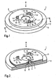
- FIG. 1 shows the principle of a heater 1 with a housing 2 with a circular bottom surface 3 made of plastic and three retaining pins 4, which protrude perpendicularly from the bottom surface.
- FIG. 2 It can be seen how on the cylindrical retaining pins 4 of the housing 2, a circular first contact plate 5 and a circular second contact plate 6 are plugged, which pinch a heating element 7 in the space.
- the retaining pins 4 each sit on a cylindrical base 9 with approximately three times the diameter D of the retaining pin 4.
- the base 9 serve the first contact plate 5 as a stop surface.
- the sockets 9 are approximately as high as a diameter of a retaining pin 4.
- Each retaining pin 4 is itself slightly beveled at the top and shows at the tip the shape of a truncated cone 10, which extends from the full diameter of the retaining pin 4 at an angle tapered from about 45 ° to about half the diameter.
- a centering portion 11 is provided, which urges the first contact plate 5 in its intended position.
- the retaining pins 4 and the base 9 and the centering 11 are integrally formed on the housing.
- the housing is preferably made of plastic.
- Both contact plates 5, 6 are made of a material with good current and thermal conduction properties, e.g. Made of aluminum. Each plate shows three openings, which are penetrated by the retaining pins 4.
- the first, lower contact plate 5 has three round openings. 8
- the heating element 7 is a circular disk and is arranged centrally between the two contact plates 5 and 6.
- the heating element 7 lies directly on the surface of the lower, first contact plate 5.
- the thickness of the heating element 7 determines the distance of the first and second contact plates 5.6 and is about half the diameter of a retaining pin.
- the second contact plate 6 is attached from above in Aufsteckides A on the retaining pins 4.
- a protruding in Aufsteckraum from the plate plane section 13 abuts against the heating element 7.
- the position, shape and size of the protruding portion 13 is adapted to the heating element 7 and is located centrally within the second contact plate. 6
- each retaining pin 4 In the assembled state penetrates each retaining pin 4 exactly one opening 8,12 exactly one contact plate 5,6, wherein the openings are each exactly superimposed.
- the positions of the apertures 8,12 and the retaining pins 4 are thus matched.
- the position and arrangement of the apertures 8,12 of both contact plates 5,6 and the retaining pins 4 is determined by the position of the heating element 7:
- the plate openings 8,12 and retaining pins 4 are each arranged in a circle around a heating element 7 and evenly distributed over the circumference of an imaginary circle K.
- the center of this circle K forms the center of the contact surface of the second contact plate 6 to the corresponding contact surface of the heating element 7, so here the center of the protruding portion 13.
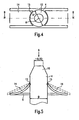
- FIG. 3 shows the arrangement of the openings and retaining pins in plan view in Aufsteckutter.
- FIG. 4 is a breakthrough 12 of the second contact plate 6 is also shown enlarged in the plan view in Aufsteckraum A.
- the apertures 12 of the second contact plate 6 are specially shaped and have an H-profile: From the material of the second contact plate two opposite spring lugs 14 are cut free, each with the length of 1-2 retaining pin diameters.
- the spring lugs 14 each extend substantially tangentially to the circumference of the imaginary circle K, wherein the width B of these spring lugs 14 is approximately a retaining pin diameter D.
- the opposing, free-standing ends 15 of the retaining pins 4 are sharp-edged and concave shaped to each receive a retaining pin 4 and to optimally support this.
- the resulting at rest distance between the free-standing ends 15 of the spring lugs 14 is large enough to accommodate the tip 10 of a retaining pin 4 between them, but smaller than the diameter D of the retaining pin 4th
- the first contact plate 5 is attached to the retaining pins 4 until it comes to rest on a stop surface on the base 9.
- the first contact plate 5 is centered by the centering 11.
- the heating element 7 is placed on a designated area in the middle of the first contact plate 5, the heating element 7 is placed.
- the second contact plate 6 is placed on the retaining pins 4 until the section 13 rests evenly and evenly on the heating element 7 and a corresponding contact pressure is present.
- the lengths of the spring sections 14 are sufficiently dimensioned and are about 1-2 retaining pin diameter D.
- the openings 12 of the second contact plate are just so wide that they can accommodate the retaining pins 4.
- the width of the spring portions 14 is therefore approximately a retaining pin diameter with some lateral clearance is provided for thermal deformation of the second contact plate 6 in relation to the retaining pins 4.
- FIG. 4 show the openings 12 second contact plate 6 in approximately an H-shaped profile.
- both contact plates are 5.6 each provided with contact terminals. About these contact terminals (not shown), the heater is connected to a power grid.
- the heating element 7 acts as a resistor, which converts electrical current into heat and transfers this heat via heat conduction to the contact plates 5, 6.
- a so-called PTC heating element is provided, which is commonly known to those skilled in the art. The operation of the same is therefore described only briefly at this point.
- a strong contact pressure between the contact plates 5,6 and the heating element 7 is advantageous in relation to the conduction of heat and electricity. If the contact pressure is lost, no current flows through the assembly, the heating element 7 can not heat the heater 1 loses its primary function.
- the PTC (Positive-Temperature-Coefficient) heating element has the characteristic that its resistance increases abruptly at a certain temperature, and therefore, the equilibrium temperature equilibrates to a certain value. This maximum temperature value can be determined and selected by the material properties of the heating element.
- the two contact plates 5.6 are heated according to the invention.
- the material of these contact plates 5.6 is made of an electrically and thermally highly conductive material, preferably aluminum. This material has a relatively high thermal expansion coefficient of the order of 23 * 10-6 m / (m * ° C).
- the housing is preferably made of plastic, a good insulator for heat and electricity and is little or not heated during operation. Depending on the operating state, large temperature gradients occur between the contact plates and the housing, which in turn generates thermoelastic deformations of the contact plates 5, 6 relative to the holding pins 4 and stresses in the spring tongues 14.
- the spring portions 14 are designed so that they - regardless of the operating condition - provide over the entire operating range for a sufficient contact pressure between the contact plates 5.6 and the heating element 7.
- the heater 1 in the principle shown is versatile and is particularly suitable for heating diesel fuel in diesel engines or crankcase gases in various types of heat engines.
Landscapes
- Engineering & Computer Science (AREA)
- Chemical & Material Sciences (AREA)
- Combustion & Propulsion (AREA)
- Mechanical Engineering (AREA)
- General Engineering & Computer Science (AREA)
- Chemical Kinetics & Catalysis (AREA)
- Resistance Heating (AREA)
- Heating, Cooling, Or Curing Plastics Or The Like In General (AREA)
- Tunnel Furnaces (AREA)
- Cookers (AREA)
Abstract
Description
Die Erfindung betrifft eine Heizeinrichtung für ein gasförmiges oder flüssiges zu beheizendes Medium, vorzugsweise Dieselkraftstoff, mit zwei in einem Gehäuse angeordneten, der Warmeübertragung dienenden Kontaktplatten zwischen denen zumindest ein scheibenförmiges Heizelement angeordnet und in Anlage an beide Kontaktplatten gehalten ist, wobei die erste und die zweite Kontaktplatte mit jeweils zumindest einem Durchbruch versehen sind, und das Gehäuse zumindest einen Haltestift aufweist, der die Durchbrüche der ersten und der zweiten Kontaktplatte in einer Aufsteckrichtung durchdringt.The invention relates to a heating device for a gaseous or liquid medium to be heated, preferably diesel fuel, arranged with two arranged in a housing, the heat transfer serving contact plates between which at least one disc-shaped heating element and is held in contact with both contact plates, wherein the first and the second Contact plate are each provided with at least one breakthrough, and the housing has at least one retaining pin which penetrates the openings of the first and the second contact plate in a Aufsteckrichtung.
Eine derartige Heizeinrichtung ist aus der
Die
Solche Heizeinrichtungen haben sich in vielerlei Anwendungen bewährt. Getrieben von den stetigen Weiterentwicklungen im Automobilbau werden dennoch immer höhere Anforderungen an einzelne Komponenten wie z.B. solche Heizeinrichtungen gestellt, besonders in Hinsicht auf Platzverbrauch, Montagefähigkeit und schließlich auch auf den Anschaffungspreis.Such heaters have been proven in many applications. Driven by the steady advancements in the automotive industry, however, ever higher demands are placed on individual components, such as Such heating devices provided, especially in terms of space, mounting capability and finally on the purchase price.
Der Erfindung liegt dadurch die Aufgabe zugrunde, eine Heizeinrichtung der eingangs erwähnten Art zu verbessern, und den Platzverbrauch sowie den Montageaufwand zu verringern, als auch die Herstellungskosten zu reduzieren.The invention is therefore based on the object to improve a heating device of the type mentioned, and to reduce the space consumption and assembly costs, as well as to reduce manufacturing costs.
Die Aufgabe wird durch eine Heizeinrichtung nach Anspruch 1 gelöst, bei der die zweite Kontaktplatte im Bereich des Durchbruchs fest mit der Kontaktplatte verbundene Federabschnitte aufweist, die durch Montieren der zweiten Kontaktplatte verformbar sind und die sich bei montierter Kontaktplatte entgegender Aufsteckrichtung an dem Haltestift abstützen um den Kontaktdruck zwischen dem Heizelement und den Kontaktplatten zu erzeugen. So erfüllt die zweite Kontaktplatte zeitgleich die Funktion der Federeinrichtung, auf die dann verzichtet werden kann. Der eingesparte Einbauraum wird nicht anderweitig benötigt und steht anderen Anwendungen zur Verfügung. Das reduziert den Platzverbrauch der gesamten Anordnung erheblich. Indem sich die Federabschnitte beim Aufstecken an den Haltestiften des Gehäuses verklemmen und verkanten, ist die zweite Kontaktplatte mit dem Gehäuse fest verbunden ohne dass eine weitere Verbindung z.B. eine Schraubverbindung erforderlich ist. Diese in der Erfindung gezeigte Klemm-/Schneidverbindung bringt eine Reihe von Vorteilen mit sich: Zunächst erspart sich der Hersteller einen weiteren Montageschritt (z.B. Verschrauben der zweiten Kontaktplatte) und kann die Heizeinrichtung schneller zusammenbauen. Ebenso wird das Material der Befestigungsschraube eingespart und die Anordnung wird leichter. Auch muss kein Werkzeug z.B. zur Verschraubung eingesetzt werden. Die erfindungsgemäße Heizeinrichtung erfordert demnach einen geringen Materialeinsatz und Fertigungsaufwand und lässt sich kostengünstig herstellen.The object is achieved by a heating device according to
Die Federabschnitte sind jeweils als eine Federzunge ausgebildet. Die Federzunge ist direkt aus dem Material der zweiten Kontaktplatte freigeschnitten und ist dabei verhältnismäßig flexibel. Die Flexibilität der Federzunge erweist sich zudem als besonders günstig falls es infolge thermoelastischer Effekte zu relativen Verformungen der zweite Kontaktplatte gegenüber den Haltestiften kommt. Sie kann die Verformungen kompensieren ohne dass der Kontaktdruck zwischen den Kontaktplatten und dem Heizelement verloren geht.The spring sections are each formed as a spring tongue. The spring tongue is cut free directly from the material of the second contact plate and is relatively flexible. The flexibility of the spring tongue also proves to be particularly favorable if it comes as a result of thermoelastic effects relative deformations of the second contact plate against the retaining pins. It can compensate for the deformations without losing the contact pressure between the contact plates and the heating element.
Es ist außerdem vorteilhaft, wenn der Haltestift aus weicherem Material gefertigt ist als der Federabschnitt. Unter Klemmung drücken sich die Federabschnitte in den Haltestift geringfügig ein, wodurch sich der Federabschnitt besser am Haltestift abstützen kann. So wird das Risiko reduziert, dass der Federabschnitt am Haltestift abrutscht und der Kontaktdruck verloren geht.It is also advantageous if the retaining pin is made of softer material than the spring section. Under clamping, the spring sections press slightly into the retaining pin, whereby the spring section can better support the retaining pin. This reduces the risk that the spring section slips off the retaining pin and the contact pressure is lost.
Es kann sich vorteilhaft erweisen, wenn der Federabschnitt mit zumindest einem Wiederhaken oder zumindest einer scharfkantigen Schneide versehen ist. Unter der Rückstellkraft des Federabschnitts verkanten die Schneiden am Haltestift und schneiden sich in das Material des Haltestifts ein. Unter Krafteinwirkung entgegen der Aufsteckrichtung ist eine solche Klemm- / Schneidfixierung in der Regel nicht zerstörungsfrei lösbar. Bei einer solchen Anordnung bleibt der Kontaktdruck stets erhalten.It may prove advantageous if the spring section is provided with at least one re-hooking or at least one sharp-edged cutting edge. Under the restoring force of the spring section, the blades tilt on the retaining pin and intersect in the material of the retaining pin. Under the action of force counter to the slip-on such a clamping / cutting fixation is usually not non-destructive solvable. With such an arrangement, the contact pressure is always maintained.
Zudem stellt es sich als hilfreich heraus, wenn im Bereich eines Durchbruchs der zweiten Kontaktplatte zumindest zwei Federzungen angeordnet sind, wobei die Federzungen vorzugsweise gleichmäßig um den Haltestift verteilt sind. Zwei Federzungen, die sich auf gegenüberliegenden Seiten des Haltestifts befinden, üben im der Summe der Vektoren eine Kraft auf den Haltestift aus, die unter gleichmäßiger Belastung entgegen der Aufsteckrichtung wirkt. Dadurch wird der Haltestift nicht quer zur Aufsteckrichtung belastet und die Lebensdauer erhöht sich wesentlich. Zudem sinkt die Gefahr, dass der Haltestift dem Druck des Federabschnitts nachgibt und sich die Klemmfixierung löst.In addition, it turns out to be helpful if at least two spring tongues are arranged in the region of a breakthrough of the second contact plate, wherein the spring tongues are preferably distributed uniformly around the retaining pin. Two spring tongues, which are located on opposite sides of the retaining pin, exert in the sum of the vectors a force on the retaining pin, which acts under uniform load against the Aufsteckrichtung. As a result, the retaining pin is not loaded transversely to the mounting direction and the life increases significantly. In addition, the risk that the retaining pin yields to the pressure of the spring section and the clamping fix dissolves.
Zudem kann es den Kontaktdruck zwischen den Kontaktplatten und dem Heizelement weiter erhöhen, wenn die zweite Kontaktplatte in Aufsteckrichtung zumindest einen aus der Plattenebene vorstehenden Abschnitt aufweist, an dem das Heizelement anliegt, wobei die Anlagefläche des vorstehenden Abschnitts in etwa der Anlagefläche des Heizelements entspricht.In addition, it can further increase the contact pressure between the contact plates and the heating element when the second contact plate in the mounting direction has at least one plate plane projecting portion on which the heating element, wherein the contact surface of the projecting portion corresponds approximately to the contact surface of the heating element.
Für den Einbau in die meisten gängigen Einrichtungen und Gehäuseteile erweist es sich vorteilhaft, wenn die Kontaktplatten im Wesentlichen kreis- bzw. ringförmig sind und im Wesentlichen parallel zueinander angeordnet sind.For installation in most common facilities and housing parts, it proves advantageous if the contact plates are substantially circular or annular and are arranged substantially parallel to each other.
Bevorzugt bei kreis- bzw. ringförmigen Kontaktplatten ist zumindest eine der Kontaktplatten mit mehreren Durchbrüchen versehen, wobei die Durchbrüche im Wesentlichen in einer Kreisform angeordnet sein können. Dadurch können die Kontaktplatten besonders gleichmäßig abgestützt werden und parallel gehalten werden.Preferably, in the case of circular or annular contact plates, at least one of the contact plates is provided with a plurality of apertures, wherein the apertures may be arranged substantially in a circular shape. As a result, the contact plates can be supported particularly uniformly and kept parallel.
Alternativ hierzu können die Kontaktplatten auch rechteckförmig ausgebildet sein um eine möglichst kompakte und leistungsstarke Bauform zu erzielen. So lassen sich mehrere z.B. rechteckige Heizelemente im Zwischenraum beider Kontaktplatten so anordnen um diesen nahezu vollständig auszufüllen.Alternatively, the contact plates may be rectangular in shape to achieve a compact and powerful design possible. Thus, several e.g. Arrange rectangular heating elements in the space between the two contact plates so as to almost completely fill them.
In einer besonders bevorzugten Ausführungsform sind beide Kontaktplatten jeweils mit mehreren Durchbrüchen versehen, die von jeweils einem Haltestift durchdrungen werden, wobei die Durchbrüche jeweils auf einem Kreis um den Mittelpunkt der Anlagefläche des nächstgelegenen Heizelements angeordnet sind. An dieser Anlagefläche wird der Kontaktdruck auf das nächstgelegene Heizelement übertragen. Auf dem Kreis um den Mittelpunkt dieser Anlagefläche sind alle Punkte gleich weit vom Mittelpunkt entfernt. Die zweite Kontaktplatte wird dadurch gleichmäßig abgestützt, so dass die Kontaktflächen des Heizelements gerade an den Anlageflächen der Kontaktplatten anliegen. So wird der Wärmeübergang zwischen dem Heizelement und den Kontaktplatten verbessert.In a particularly preferred embodiment, both contact plates are each provided with a plurality of apertures, which are penetrated by a respective retaining pin, wherein the apertures are each arranged on a circle around the center of the contact surface of the nearest heating element. At this contact surface, the contact pressure is transferred to the nearest heating element. On the circle around the center of this contact surface, all points are equidistant from the center point. The second contact plate is thereby supported evenly, so that the contact surfaces of the heating element just bear against the contact surfaces of the contact plates. This improves the heat transfer between the heating element and the contact plates.
Um thermoelastische Verformungen der zweiten Kontaktplatte in Relation zu den Haltestiften besser kompensieren zu können erweist es sich als vorteilhaft, wenn die Federzungen am Durchbruch der zweiten Kontaktplatte im Wesentlichen tangential zu einem Kreis um den Mittelpunkt der Auflagefläche des nächstgelegenen Heizelements ausgerichtet sind. Dehnt sich die zweite Kontaktplatte im Vergleich zum Gehäuse überproportional aus, so wächst der Durchmesser des Verbindungskreises aller Durchbrüche. Die Federabschnitte, die sich mit den Haltestiften im Eingriff befinden, verbiegen sich unter diesem Einfluss geringfügig, und zwar gleichmäßig zum Mittelpunkt des Kreises hin, ohne dass der Kontaktdruck verloren geht.In order to better compensate for thermo-elastic deformations of the second contact plate in relation to the retaining pins, it proves to be advantageous if the spring tongues are aligned at the opening of the second contact plate substantially tangential to a circle around the center of the bearing surface of the nearest heating element. If the second contact plate expands disproportionately in comparison to the housing, the diameter of the connection circle of all openings increases. The spring portions engaged with the retaining pins bend slightly under this influence, uniformly toward the center of the circle, without losing the contact pressure.
Es erweist sich zudem als günstig, wenn der Haltestift dem Heizelement benachbart angeordnet ist und das Heizelement dadurch quer zur Aufsteckrichtung fixiert. So kann das Heizelement ständig in Position gehalten werden, was z.B. die Montage erheblich vereinfacht. Auch verhindert dies ein Verschieben des Heizelements, falls z.B. infolge starker Erschütterung der Kontaktdruck kurzzeitig verringert wird bzw. verloren geht, und reduziert so die Versagenswahrscheinlichkeit der Heizeinrichtung.It also proves to be advantageous if the retaining pin is arranged adjacent to the heating element and thereby fixes the heating element transversely to the mounting direction. Thus, the heating element can be kept constantly in position, which is e.g. the assembly considerably simplified. This also prevents a displacement of the heating element, if e.g. due to strong vibration of the contact pressure is briefly reduced or lost, and thus reduces the probability of failure of the heater.
Um dieser Gefahr vorzubeugen kann es sich auch als hilfreich erweisen das Heizelement mit zumindest einer Halteöffnung zu versehen, die der Haltestift durchdringt.In order to prevent this danger, it may prove to be helpful to provide the heating element with at least one retaining opening, which penetrates the retaining pin.
Jedes Heizelement ist sicher in einer Richtung quer zur Aufsteckrichtung positioniert, wenn im Umfangsbereich des Heizelements zumindest drei Haltestifte vorgesehen sind, die vorzugsweise gleichmäßig entlang des Umfangs des Heizelements angeordnet sind. Auch lassen sich dadurch die Kontaktflächen des Heizelements und die Anlageflächen der Kontaktplatten gleichmäßig und gerade in Anlage halten.Each heating element is securely positioned in a direction transverse to the mounting direction, if at least three retaining pins are provided in the peripheral region of the heating element, which are preferably arranged uniformly along the circumference of the heating element. Also, this allows the contact surfaces of the heating element and the contact surfaces of the contact plates hold evenly and just in contact.
Zudem erleichtert es das Herstellungsverfahren erheblich, wenn das Gehäuse aus Kunststoff hergestellt ist. Kunststoffe sind in der Regel preisgünstig in der Anschaffung, überdies gestaltet sich die Formgebung für Kunststoffprodukte verhältnismäßig einfach. Kunststoffe wirken in der Regel zudem als Isolator für Wärme und Strom. So kann z.B. ungewollter Wärmeverlust über das Gehäuse verhindert werden.In addition, it facilitates the manufacturing process considerably if the housing is made of plastic. Plastics are generally inexpensive to buy, and the shape of plastic products is relatively simple. As a rule, plastics also act as an insulator for heat and electricity. Thus, e.g. unwanted heat loss through the housing can be prevented.
In einer besonders bevorzugten Gestaltungsform ist der Haltestift im Wesentlichen zylindrisch und dessen Durchmesser beträgt in etwa die zweifache Dicke des Heizelements.In a particularly preferred embodiment, the retaining pin is substantially cylindrical and its diameter is approximately twice the thickness of the heating element.
Ein Federabschnitt kann sich besonders gut an einem Haltestift abstützen, wenn dabei die Breite der Federabschnitte vorzugsweise dem Durchmesser des Haltestifts entspricht.A spring section can be supported particularly well on a retaining pin, if the width of the spring sections preferably corresponds to the diameter of the retaining pin.
Die Federeigenschaften des Federabschnitts sind besonders günstig, wenn die freigeschnittene Länge der Federabschnitte bevorzugt das Ein- bis Zweifache, vorzugsweise das Eineinhalbfache des Haltestiftdurchmessers beträgt.The spring properties of the spring section are particularly favorable if the cut-free length of the spring sections is preferably one to two times, preferably one and a half times, the retaining pin diameter.
Es ist von Vorteil für das Herstellungsverfahren, wenn die Durchbrüche der zweiten Kontaktplatte im Wesentlichen ein H-Profil aufweisen. Dieses Profil lässt sich mit einer geeigneten Stanzvorrichtung leicht anbringen, wobei die Federabschnitte implizit mit freigeschnitten werden.It is advantageous for the manufacturing method, if the openings of the second contact plate have a substantially H-profile. This profile can be easily attached with a suitable punching device, wherein the spring sections are implicitly cut with.
Wenn die Haltestifte auf zylindrischen Sockeln sitzen, die bevorzugt den zwei- bis dreifachen Haltestiftdurchmesser aufweisen, können diese Sockel der ersten Kontaktplatte eine hervorragende Anlagefläche bieten. Der Kraftverlauf durch die Anordnung ist so besonders günstig, da sich die zweite Kontaktplatte am Haltestift abstützt, diesen Kontaktdruck über das Heizelement auf die erste Kontaktplatte überträgt, und die erste Kontaktplatte wiederum die Kraft auf die Sockel am Fuß der Haltestifte weitergibt. Der Kraftfluss durch die Anordnung verläuft im Wesentlichen senkrecht. Also verringert sich die Wahrscheinlichkeit, dass sich eine der Kontaktplatten z.B. infolge eines sehr hohen Kontaktdrucks verformt, da nur geringe bis keine Querkräfte vorkommen.When the retention pins are seated on cylindrical sockets, which preferably have two to threefold retention pin diameters, these sockets of the first contact plate can provide a superior contact surface. The force curve through the arrangement is so particularly favorable, since the second contact plate is supported on the retaining pin, this contact pressure on the heating element transmits to the first contact plate, and the first contact plate in turn passes the force on the base at the bottom of the retaining pins. The flow of force through the assembly is substantially vertical. Thus, the likelihood of one of the contact plates, e.g. deformed due to a very high contact pressure, since only small to no shear forces occur.
Vorteilhaft erweist es sich zudem, wenn an den Haltestiften Abschnitte vorgesehen sind, die sowohl die erste Kontaktplatte als auch das Heizelement ausrichten. So können die Positionen der einzelnen Bauteile mit wenigen Anlagepunkten bzw. Zentrierabschnitten relativ zueinander gesichert werden.It also proves advantageous if sections are provided on the retaining pins which align both the first contact plate and the heating element. Thus, the positions of the individual components with a few contact points or centering sections can be secured relative to each other.
Es verringert das Risiko, dass ein Federabschnitt an einem Haltestift abrutscht, wenn die Federabschnitte an dem zum Abstützen am Haltestift vorgesehen Ende eine Kontur aufweisen, die im Wesentlichen der Kontur des Haltestifts an der Abstützfläche entspricht.It reduces the risk of having a spring section Slips on a retaining pin when the spring sections have at the end provided for supporting on the retaining pin a contour that corresponds substantially to the contour of the retaining pin on the support surface.
Nachfolgend werden Aufbau und Funktionsweise einer erfindungsgemäßen Heizeinrichtung anhand der Figuren erläutert. Es zeigen:
-
Fig.1 : Prinzipdarstellung der Heizeinrichtung in der Gesamtansicht. -
Fig.2 : Gesamtansicht der Heizeinrichtung im Schnitt durch die LinieA-A aus Figur 1 Fig.3 : Draufsicht auf die Heizeinrichtung in der Aufsteckrichtung. -
Fig.4 : Draufsicht auf einen Durchbruch der zweiten Kontaktplatte in der Aufsteckrichtung im montierten Zustand (vergrößerte Darstellung). -
Fig.5 : Schnitt durch die LinieB-B aus Figur 4 in kaltem und warmem Zustand der zweiten Kontaktplatte.
-
Fig.1 : Schematic representation of the heater in the overall view. -
Fig.2 : General view of the heater in section through the line AAFIG. 1 Figure 3 : Top view of the heater in the slip-on direction. -
Figure 4 : Top view of a breakthrough of the second contact plate in the slip-on direction in the mounted state (enlarged view). -
Figure 5 : Cut through the line BBFIG. 4 in cold and warm condition of the second contact plate.
Die Haltestifte 4 sitzen jeweils auf einem zylindrischen Sockel 9 mit in etwa dem dreifachen Durchmesser D des Haltestifts 4. Die Sockel 9 dienen der ersten Kontaktplatte 5 als Anschlagsfläche. In der gezeigten Ausführungsform sind die Sockel 9 in etwa so hoch wie ein Durchmesser eines Haltestifts 4. Jeder Haltestift 4 ist selbst oben leicht angeschrägt und zeigt an der Spitze die Form eines Kegelstumpfs 10, der sich von dem vollen Durchmesser des Haltestifts 4 in einem Winkel von etwa 45° auf etwa den halben Durchmesser verjüngt. Am Sockel 9 jedes Haltestifts 4 ist ein Zentrierabschnitt 11 vorgesehen, der die erste Kontaktplatte 5 in ihre vorgesehene Position drängt. Die Haltestifte 4 sowie die Sockel 9 und die Zentrierabschnitte 11 sind einstückig am Gehäuse angeformt. Das Gehäuse besteht vorzugsweise aus Kunststoff.
The retaining pins 4 each sit on a
Beide Kontaktplatten 5,6 sind aus einem Material mit guten Strom- und Wärmeleiteigenschaften, z.B. Aluminium hergestellt. Jede Platte zeigt jeweils drei Durchbrüche, die von den Haltestiften 4 durchdrungen werden.Both
Die erste, untere Kontaktplatte 5 hat drei runde Durchbrüche 8.The first,
In der gezeigten Ausführungsform ist das Heizelement 7 eine kreisrunde Scheibe und ist mittig zwischen den beiden Kontaktplatten 5 und 6 angeordnet. Das Heizelement 7 liegt dabei direkt auf der Oberfläche der unteren, ersten Kontaktplatte 5. Die Dicke des Heizelements 7 bestimmt den Abstand der ersten und zweiten Kontaktplatten 5,6 und beträgt etwa den halben Durchmesser eines Haltestifts.In the embodiment shown, the heating element 7 is a circular disk and is arranged centrally between the two
Die zweite Kontaktplatte 6 ist von oben in Aufsteckrichtung A auf die Haltestifte 4 aufgesteckt. Ein in Aufsteckrichtung aus der Plattenebene vorstehender Abschnitt 13 liegt an dem Heizelement 7 an. Die Lage, Form und Größe des vorstehenden Abschnitts 13 ist dem Heizelement 7 angepasst und liegt mittig innerhalb der zweiten Kontaktplatte 6.The
Im montierten Zustand durchdringt jeder Haltestift 4 genau einen Durchbruch 8,12 genau einer Kontaktplatte 5,6, wobei die Durchbrüche jeweils genau übereinander liegen. Die Positionen der Durchbrüche 8,12 und der Haltestifte 4 sind also aufeinander abgestimmt.
Die Lage und Anordnung der Durchbrüche 8,12 beider Kontaktplatten 5,6 sowie der Haltestifte 4 wird von der Position des Heizelements 7 bestimmt:In the assembled state penetrates each retaining
The position and arrangement of the
In einer Draufsicht auf die Anordnung in Aufsteckrichtung A sind die Plattendurchbrüche 8,12 und Haltestifte 4 jeweils kreisförmig um ein Heizelement 7 angeordnet und gleichmäßig auf den Umfang eines imaginären Kreises K verteilt. Den Mittelpunkt dieses Kreises K bildet der Mittelpunkt der Anlagefläche der zweiten Kontaktplatte 6 an die entsprechende Kontaktfläche des Heizelements 7, hier also der Mittelpunkt des vorstehenden Abschnitts 13. In der gezeigten Anordnung sind auf einer Kontaktplatte 5,6 jeweils drei Durchbrüche 8,12 pro Heizelement 7 vorgesehen, die von drei Haltestiften 4 durchdrungen werden, die jeweils um 120° versetzt sind.
In
Die Wirkungsweise der erfindungsgemäßen Heizeinrichtung wird anhand des Ausführungsbeispiels näher erläutert.The mode of operation of the heating device according to the invention will be explained in more detail with reference to the embodiment.
Zunächst wird die erste Kontaktplatte 5 auf die Haltestifte 4 aufgesteckt bis sie auf einer Anschlagsfläche am Sockel 9 zum Liegen kommt. Die erste Kontaktplatte 5 wird durch die Zentrierabschnitte 11 zentriert. Auf einen dafür vorgesehenen Bereich mittig auf der ersten Kontaktplatte 5 wird das Heizelement 7 platziert. Die Zentrierabschnitte 11, die durch die Durchbrüche 8 der ersten Kontaktplatte 5 ragen, zentrieren dabei auch das Heizelement 7.First, the
Danach wird die zweite Kontaktplatte 6 auf die Haltestifte 4 gesteckt bis der Abschnitt 13 gerade und gleichmäßig am Heizelement 7 anliegt und ein entsprechender Kontaktdruck vorhanden ist. Beim Aufstecken verformen sich die Federnasen 14 jeweils entgegen der Aufsteckrichtung A und stützen sich am Haltestift 4 ab. Die Längen der Federabschnitte 14 sind ausreichend dafür bemessen und betragen etwa 1-2 Haltestiftdurchmesser D. Die Durchbrüche 12 der zweiten Kontaktplatte sind gerade so breit, dass sie die Haltestifte 4 aufnehmen können. Die Breite der Federabschnitte 14 beträgt demnach in etwa einen Haltestiftdurchmesser wobei seitlich etwas Spiel vorgesehen ist für thermische Verformungen der zweiten Kontaktplatte 6 in Relation zu den Haltestiften 4. In der Ansicht der
Zum Betrieb der Heizeinrichtung werden beide Kontaktplatten 5,6 jeweils mit Kontaktanschlüssen versehen. Über diese Kontaktanschlüsse (nicht gezeigt) wird die Heizeinrichtung an ein Stromnetz angeschlossen. Das Heizelement 7 wirkt dabei als Widerstand, der elektrischen Strom in Wärme umwandelt und diese Wärme über Wärmeleitung auf die Kontaktplatten 5,6 überträgt. Als Heizelement 7 ist ein sogenanntes PTC-Heizelement vorgesehen, das dem Fachmann gemeinhin bekannt ist. Die Funktionsweise desselben wird deshalb an dieser Stelle auch nur kurz beschrieben.To operate the heater both contact plates are 5.6 each provided with contact terminals. About these contact terminals (not shown), the heater is connected to a power grid. The heating element 7 acts as a resistor, which converts electrical current into heat and transfers this heat via heat conduction to the
Ein starker Kontaktdruck zwischen den Kontaktplatten 5,6 und dem Heizelement 7 ist dabei vorteilhaft in Bezug auf die Leitung von Wärme und Strom. Geht der Kontaktdruck verloren so fließt kein Strom durch die Anordnung, das Heizelement 7 kann nicht heizen die Heizeinrichtung 1 verliert ihre primäre Funktion.A strong contact pressure between the
Im Betrieb einer derartigen Heizeinrichtung wird ein flüssiges oder gasförmiges Medium um die Kontaktplatten und das Heizelement gespült und dadurch aufgeheizt. Das PTC (Positive-Temperature-Coefficient)-Heizelement hat die Eigenschaft, dass dessen Widerstand bei einer bestimmten Temperatur sprunghaft ansteigt und sich die Maximaltemperatur im Gleichgewichtszustand deshalb auf einem bestimmten Wert einpendelt. Dieser maximale Temperaturwert kann durch die Materialeigenschaften des Heizelements bestimmt und gewählt werden.During operation of such a heating device, a liquid or gaseous medium is flushed around the contact plates and the heating element and thereby heated. The PTC (Positive-Temperature-Coefficient) heating element has the characteristic that its resistance increases abruptly at a certain temperature, and therefore, the equilibrium temperature equilibrates to a certain value. This maximum temperature value can be determined and selected by the material properties of the heating element.
Im Betrieb werden die beiden Kontaktplatten 5,6 erfindungsgemäß aufgeheizt. Das Material dieser Kontaktplatten 5,6 ist aus einem elektrisch und thermisch stark leitfähigem Material, vorzugsweise Aluminium, hergestellt. Dieses Material hat einen verhältnismäßig großen Wärmeausdehnungskoeffizienten in der Größenordnung von 23*10-6 m/(m*°C). Das Gehäuse besteht vorzugsweise aus Kunststoff, einem guten Isolator für Wärme und Strom und wird im Betrieb wenig bis gar nicht aufgeheizt. Je nach Betriebszustand treten große Temperaturgradienten zwischen den Kontaktplatten und dem Gehäuse auf, was wiederum thermoelastische Verformungen der Kontaktplatten 5,6 relativ zu den Haltestiften 4 und Spannungen in den Federzungen 14 erzeugt. Die Federabschnitte 14 sind jedoch so gestaltet, dass sie - unabhängig vom Betriebszustand - über den gesamten Betriebsbereich für einen ausreichenden Kontaktdruck zwischen den Kontaktplatten 5,6 und dem Heizelement 7 sorgen.In operation, the two contact plates 5.6 are heated according to the invention. The material of these contact plates 5.6 is made of an electrically and thermally highly conductive material, preferably aluminum. This material has a relatively high thermal expansion coefficient of the order of 23 * 10-6 m / (m * ° C). The housing is preferably made of plastic, a good insulator for heat and electricity and is little or not heated during operation. Depending on the operating state, large temperature gradients occur between the contact plates and the housing, which in turn generates thermoelastic deformations of the
Die Heizeinrichtung 1 in dem gezeigten Prinzip ist vielseitig einsetzbar und eignet sich insbesondere für das Beheizen von Dieselkraftstoff in Dieselaggregaten oder Kurbelgehäusegasen in verschiedenen Arten von Wärmekraftmaschinen.The
Für die Funktion der Heizeinrichtung sind Gestaltungsform, Anordnung und Anzahl der Kontaktplatten 5,6, der Heizelemente 7 und der Haltestifte 4 sowie die Form des Gehäuses 2 nicht entscheidend und können entsprechenden Bedürfnissen angepasst werden ohne den Schutzbereich der Erfindung zu verlassen.For the function of the heater design form, arrangement and number of
Claims (21)
- Heating device (1) for a gaseous or liquid medium to be heated having two contact plates (5, 6) for heat transfer disposed in a housing (2), between which at least one disc-shaped heating element (7) is disposed and is held in contact with both contact plates (5, 6), wherein the first and second contact plates (5, 6) are provided with at least one respective perforation (8, 12), and the housing (2) has at least one holding pin (4) which penetrates the perforations (8, 12) of the first and second contact plates (5, 6) in a mounting direction (A), characterised in that the second contact plate (6) has resilient sections (14) which are connected rigidly to the second contact plate (6) in the region of the perforation (12), which are spring tongues cut free directly from the material of the second contact plate, and which are deformable by mounting of the second contact plate (6), whereby the mounted second contact plate (6) bears on the holding pin (4) against the mounting direction (A) in order to generate the contact pressure between the heating element (7) and the contact plates (5, 6).
- Heating device (1) according to Claim 1, characterised in that the holding pin (4) is manufactured from softer material than the resilient section (14).
- Heating device (1) according to one of the preceding claims, characterised in that the resilient section (14) is provided with at least one barb or at least one sharp-edged blade (15) and is in engagement with the holding pin (4).
- Heating device (1) according to one of the preceding claims, characterised in that in the region of a perforation (12) of the second contact plate (6) at least two spring tongues (14) are disposed, in which case the spring tongues (14) are distributed preferably evenly around the holding pin (4).
- Heating device (1) according to one of the preceding claims, characterised in that the second contact plate (6) has at least one section (13) projecting from the plate plane in the mounting direction (A), which section the heating element (7) abuts, in which case the contact area of the projecting section (13) roughly corresponds to the contact area of the heating element (7).
- Heating device (1) according to one of the preceding claims, characterised in that the contact plates (5, 6) are shaped substantially circularly or annularly and are arranged substantially parallel to one another.
- Heating device (1) according to one of the preceding claims, characterised in that at least one of the contact plates (5, 6) is provided with plural perforations (8, 12), in which case the perforations (8, 12) are arranged substantially in a circular shape (K).
- Heating device (1) according to one of the preceding claims, characterised in that the contact plates (5, 6) are substantially rectangular.
- Heating device (1) according to one of the preceding claims, characterised in that both contact plates (5, 6) are each provided with plural perforations (8, 12) which are penetrated respectively by a holding pin (4), in which case the perforations (8, 12) are respectively arranged in a circle (K) around the centre point of the contact area of the proximal heating element (7).
- Heating device (1) according to one of the preceding claims, characterised in that the resilient sections (14) on the perforation (12) of the second contact plate (6) are oriented substantially tangential to a circle (K) around the centre point of the bearing face of the proximal heating element (7).
- Heating device (1) according to one of the preceding claims, characterised in that the holding pin (4) is disposed adjacent to the heating element (7) and thus fixes the heating element (7) transverse to the mounting direction (A).
- Heating device (1) according to one of the preceding claims, characterised in that the heating element (7) is provided with at least one holding aperture which the holding pin (4) penetrates.
- Heating device (1) according to one of the preceding claims, characterised in that in the circumferential region of the heating element (7) at least three holding pins (4) are provided which are arranged preferably evenly along the circumference of the heating element (7).
- Heating device (1) according to one of the preceding claims, characterised in that the housing is manufactured from plastics material.
- Heating device (1) according to one of the preceding claims, characterised in that the holding pin (4) is substantially cylindrical and its diameter (D) is equal to roughly twice the thickness of the heating element (7).
- Heating device (1) according to one of the preceding claims, characterised in that the width of the resilient sections (14) preferably corresponds to the diameter (D) of the holding pin.
- Heating device (1) according to one of the preceding claims, characterised in that the freely cut length of the resilient sections (14) is preferably once to twice, preferably one-and-a-half times the size of the holding pin diameter (D).
- Heating device (1) according to one of the preceding claims, characterised in that the perforations (12) of the second contact plate (6) substantially have an H-profile.
- Heating device (1) according to one of the preceding claims, characterised in that the holding pins (4) rest on cylindrical bases (9) which are preferably two to three times the size of the holding pin diameter (D).
- Heating device (1) according to one of the preceding claims, characterised in that on the holding pins (4) sections (11) are provided which orient both the first contact plate (5) and the heating element (7).
- Heating device (1) according to one of the preceding claims, characterised in that the resilient sections (14) have on the end provided for supporting on the holding pin (4) a contour which substantially corresponds to the contour of the holding pin (4) on the support face.
Priority Applications (4)
| Application Number | Priority Date | Filing Date | Title |
|---|---|---|---|
| EP03019864A EP1510688B2 (en) | 2003-09-01 | 2003-09-01 | Heating device for a medium to be heated |
| AT03019864T ATE390551T1 (en) | 2003-09-01 | 2003-09-01 | HEATING DEVICE FOR A MEDIUM TO BE HEATED |
| DE50309474T DE50309474D1 (en) | 2003-09-01 | 2003-09-01 | Heating device for a medium to be heated |
| PCT/EP2004/009542 WO2005024221A1 (en) | 2003-09-01 | 2004-08-26 | Heating device for a medium to be heated |
Applications Claiming Priority (1)
| Application Number | Priority Date | Filing Date | Title |
|---|---|---|---|
| EP03019864A EP1510688B2 (en) | 2003-09-01 | 2003-09-01 | Heating device for a medium to be heated |
Publications (3)
| Publication Number | Publication Date |
|---|---|
| EP1510688A1 EP1510688A1 (en) | 2005-03-02 |
| EP1510688B1 EP1510688B1 (en) | 2008-03-26 |
| EP1510688B2 true EP1510688B2 (en) | 2011-10-05 |
Family
ID=34089654
Family Applications (1)
| Application Number | Title | Priority Date | Filing Date |
|---|---|---|---|
| EP03019864A Expired - Lifetime EP1510688B2 (en) | 2003-09-01 | 2003-09-01 | Heating device for a medium to be heated |
Country Status (4)
| Country | Link |
|---|---|
| EP (1) | EP1510688B2 (en) |
| AT (1) | ATE390551T1 (en) |
| DE (1) | DE50309474D1 (en) |
| WO (1) | WO2005024221A1 (en) |
Families Citing this family (3)
| Publication number | Priority date | Publication date | Assignee | Title |
|---|---|---|---|---|
| DE202005006326U1 (en) | 2005-04-20 | 2006-08-31 | Dbk David + Baader Gmbh | Heating device for a gaseous or liquid medium to be heated |
| DE102009055084A1 (en) * | 2009-12-21 | 2011-06-22 | Robert Bosch GmbH, 70469 | Heating device for a fuel filter |
| DE102011000246A1 (en) | 2010-11-26 | 2012-05-31 | Dbk David + Baader Gmbh | heater |
Citations (1)
| Publication number | Priority date | Publication date | Assignee | Title |
|---|---|---|---|---|
| WO2001092714A2 (en) † | 2000-05-31 | 2001-12-06 | Parker-Hannifin Corporation | Fuel filter assembly with priming pump and heating device |
Family Cites Families (5)
| Publication number | Priority date | Publication date | Assignee | Title |
|---|---|---|---|---|
| EP0162939B1 (en) | 1984-05-29 | 1987-11-11 | David + Baader DBK Spezialfabrik Elektrischer Apparate und Heizwiderstände GmbH | Fuel heater for a diesel engine |
| US4713524A (en) * | 1986-04-21 | 1987-12-15 | Gte Products Corporation | PTC fuel heater for heating alcohol fuel |
| JPH0773958A (en) * | 1993-09-03 | 1995-03-17 | Texas Instr Japan Ltd | Heating device |
| EP0657199A2 (en) * | 1993-12-13 | 1995-06-14 | Stanadyne Automotive Corp. | Heater module for filter assembly |
| DE50014999D1 (en) | 2000-05-25 | 2008-04-10 | Dbk David & Baader Gmbh | PTC heater |
-
2003
- 2003-09-01 EP EP03019864A patent/EP1510688B2/en not_active Expired - Lifetime
- 2003-09-01 DE DE50309474T patent/DE50309474D1/en not_active Expired - Lifetime
- 2003-09-01 AT AT03019864T patent/ATE390551T1/en not_active IP Right Cessation
-
2004
- 2004-08-26 WO PCT/EP2004/009542 patent/WO2005024221A1/en not_active Ceased
Patent Citations (1)
| Publication number | Priority date | Publication date | Assignee | Title |
|---|---|---|---|---|
| WO2001092714A2 (en) † | 2000-05-31 | 2001-12-06 | Parker-Hannifin Corporation | Fuel filter assembly with priming pump and heating device |
Also Published As
| Publication number | Publication date |
|---|---|
| WO2005024221A1 (en) | 2005-03-17 |
| ATE390551T1 (en) | 2008-04-15 |
| DE50309474D1 (en) | 2008-05-08 |
| EP1510688A1 (en) | 2005-03-02 |
| EP1510688B1 (en) | 2008-03-26 |
Similar Documents
| Publication | Publication Date | Title |
|---|---|---|
| EP1564503B1 (en) | Electical heating device of low height | |
| EP3668272B1 (en) | Holding body, heating apparatus and method | |
| DE3048452C2 (en) | Electric heater | |
| EP1158158B1 (en) | PTC heating device | |
| DE2460219B2 (en) | Valve that responds to the effects of heat | |
| DE2715728A1 (en) | THERMOSTAT | |
| EP1510688B2 (en) | Heating device for a medium to be heated | |
| DE4225149A1 (en) | Electric heater for diesel fuel | |
| EP2126327A1 (en) | Device for producing a temperature gradient | |
| DE102020209923B3 (en) | Circuit carrier arrangement and method for producing such a circuit carrier arrangement | |
| DE102010021165A1 (en) | heating arrangement | |
| EP3738144B1 (en) | Fastening unit for connecting thermally stressed components to each other | |
| EP1510686B1 (en) | Heating device for a medium to be heated | |
| EP1510685B1 (en) | Heating device for a medium to be heated | |
| EP1353131A2 (en) | Electric heater, especially for a vehicle | |
| EP1523224B2 (en) | Electrical heating cartridge | |
| EP2458191A1 (en) | Heating device | |
| EP4335245B1 (en) | Holding device, heater and method | |
| DE69905420T2 (en) | Steam generator with plate for direct evaporation | |
| DE102022130226A1 (en) | Battery for a motor vehicle | |
| DE20011315U1 (en) | Radiant heaters for hobs | |
| EP1168887A1 (en) | Spring-mounted spreading device, especially for heating elements | |
| WO2025185875A1 (en) | Lead frame assembly for installing into a tank valve or a tank end stopper, component group and system | |
| WO2025157558A1 (en) | Lead frame assembly for installation in a tank valve or a tank end plug, a component group and a system | |
| DE19706250A1 (en) | Electrical control apparatus for domestic heating apparatus, such as electric oven cam drive switch |
Legal Events
| Date | Code | Title | Description |
|---|---|---|---|
| PUAI | Public reference made under article 153(3) epc to a published international application that has entered the european phase |
Free format text: ORIGINAL CODE: 0009012 |
|
| AK | Designated contracting states |
Kind code of ref document: A1 Designated state(s): AT BE BG CH CY CZ DE DK EE ES FI FR GB GR HU IE IT LI LU MC NL PT RO SE SI SK TR |
|
| AX | Request for extension of the european patent |
Extension state: AL LT LV MK |
|
| RAP1 | Party data changed (applicant data changed or rights of an application transferred) |
Owner name: DBK DAVID + BAADER GMBH |
|
| 17P | Request for examination filed |
Effective date: 20050323 |
|
| AKX | Designation fees paid |
Designated state(s): AT BE BG CH CY CZ DE DK EE ES FI FR GB GR HU IE IT LI LU MC NL PT RO SE SI SK TR |
|
| 17Q | First examination report despatched |
Effective date: 20061228 |
|
| GRAP | Despatch of communication of intention to grant a patent |
Free format text: ORIGINAL CODE: EPIDOSNIGR1 |
|
| GRAS | Grant fee paid |
Free format text: ORIGINAL CODE: EPIDOSNIGR3 |
|
| GRAA | (expected) grant |
Free format text: ORIGINAL CODE: 0009210 |
|
| AK | Designated contracting states |
Kind code of ref document: B1 Designated state(s): AT BE BG CH CY CZ DE DK EE ES FI FR GB GR HU IE IT LI LU MC NL PT RO SE SI SK TR |
|
| REG | Reference to a national code |
Ref country code: GB Ref legal event code: FG4D Free format text: NOT ENGLISH |
|
| REG | Reference to a national code |
Ref country code: CH Ref legal event code: EP Ref country code: IE Ref legal event code: FG4D Free format text: LANGUAGE OF EP DOCUMENT: GERMAN |
|
| REF | Corresponds to: |
Ref document number: 50309474 Country of ref document: DE Date of ref document: 20080508 Kind code of ref document: P |
|
| PG25 | Lapsed in a contracting state [announced via postgrant information from national office to epo] |
Ref country code: FI Free format text: LAPSE BECAUSE OF FAILURE TO SUBMIT A TRANSLATION OF THE DESCRIPTION OR TO PAY THE FEE WITHIN THE PRESCRIBED TIME-LIMIT Effective date: 20080326 |
|
| NLV1 | Nl: lapsed or annulled due to failure to fulfill the requirements of art. 29p and 29m of the patents act | ||
| PG25 | Lapsed in a contracting state [announced via postgrant information from national office to epo] |
Ref country code: SI Free format text: LAPSE BECAUSE OF FAILURE TO SUBMIT A TRANSLATION OF THE DESCRIPTION OR TO PAY THE FEE WITHIN THE PRESCRIBED TIME-LIMIT Effective date: 20080326 |
|
| REG | Reference to a national code |
Ref country code: IE Ref legal event code: FD4D |
|
| PG25 | Lapsed in a contracting state [announced via postgrant information from national office to epo] |
Ref country code: CZ Free format text: LAPSE BECAUSE OF FAILURE TO SUBMIT A TRANSLATION OF THE DESCRIPTION OR TO PAY THE FEE WITHIN THE PRESCRIBED TIME-LIMIT Effective date: 20080326 Ref country code: ES Free format text: LAPSE BECAUSE OF FAILURE TO SUBMIT A TRANSLATION OF THE DESCRIPTION OR TO PAY THE FEE WITHIN THE PRESCRIBED TIME-LIMIT Effective date: 20080707 Ref country code: SK Free format text: LAPSE BECAUSE OF FAILURE TO SUBMIT A TRANSLATION OF THE DESCRIPTION OR TO PAY THE FEE WITHIN THE PRESCRIBED TIME-LIMIT Effective date: 20080326 Ref country code: PT Free format text: LAPSE BECAUSE OF FAILURE TO SUBMIT A TRANSLATION OF THE DESCRIPTION OR TO PAY THE FEE WITHIN THE PRESCRIBED TIME-LIMIT Effective date: 20080901 Ref country code: SE Free format text: LAPSE BECAUSE OF FAILURE TO SUBMIT A TRANSLATION OF THE DESCRIPTION OR TO PAY THE FEE WITHIN THE PRESCRIBED TIME-LIMIT Effective date: 20080626 |
|
| PG25 | Lapsed in a contracting state [announced via postgrant information from national office to epo] |
Ref country code: RO Free format text: LAPSE BECAUSE OF FAILURE TO SUBMIT A TRANSLATION OF THE DESCRIPTION OR TO PAY THE FEE WITHIN THE PRESCRIBED TIME-LIMIT Effective date: 20080326 Ref country code: NL Free format text: LAPSE BECAUSE OF FAILURE TO SUBMIT A TRANSLATION OF THE DESCRIPTION OR TO PAY THE FEE WITHIN THE PRESCRIBED TIME-LIMIT Effective date: 20080326 |
|
| ET | Fr: translation filed | ||
| PLBI | Opposition filed |
Free format text: ORIGINAL CODE: 0009260 |
|
| 26 | Opposition filed |
Opponent name: EICHENAUER HEIZELEMENTE GMBH & CO.KG Effective date: 20081218 |
|
| PLAX | Notice of opposition and request to file observation + time limit sent |
Free format text: ORIGINAL CODE: EPIDOSNOBS2 |
|
| PG25 | Lapsed in a contracting state [announced via postgrant information from national office to epo] |
Ref country code: DK Free format text: LAPSE BECAUSE OF FAILURE TO SUBMIT A TRANSLATION OF THE DESCRIPTION OR TO PAY THE FEE WITHIN THE PRESCRIBED TIME-LIMIT Effective date: 20080326 Ref country code: IE Free format text: LAPSE BECAUSE OF FAILURE TO SUBMIT A TRANSLATION OF THE DESCRIPTION OR TO PAY THE FEE WITHIN THE PRESCRIBED TIME-LIMIT Effective date: 20080326 |
|
| PLBB | Reply of patent proprietor to notice(s) of opposition received |
Free format text: ORIGINAL CODE: EPIDOSNOBS3 |
|
| BERE | Be: lapsed |
Owner name: DBK DAVID + BAADER G.M.B.H. Effective date: 20080930 |
|
| PG25 | Lapsed in a contracting state [announced via postgrant information from national office to epo] |
Ref country code: MC Free format text: LAPSE BECAUSE OF NON-PAYMENT OF DUE FEES Effective date: 20080930 Ref country code: BG Free format text: LAPSE BECAUSE OF FAILURE TO SUBMIT A TRANSLATION OF THE DESCRIPTION OR TO PAY THE FEE WITHIN THE PRESCRIBED TIME-LIMIT Effective date: 20080626 Ref country code: EE Free format text: LAPSE BECAUSE OF FAILURE TO SUBMIT A TRANSLATION OF THE DESCRIPTION OR TO PAY THE FEE WITHIN THE PRESCRIBED TIME-LIMIT Effective date: 20080326 |
|
| REG | Reference to a national code |
Ref country code: CH Ref legal event code: PL |
|
| PG25 | Lapsed in a contracting state [announced via postgrant information from national office to epo] |
Ref country code: BE Free format text: LAPSE BECAUSE OF NON-PAYMENT OF DUE FEES Effective date: 20080930 |
|
| PG25 | Lapsed in a contracting state [announced via postgrant information from national office to epo] |
Ref country code: IT Free format text: LAPSE BECAUSE OF FAILURE TO SUBMIT A TRANSLATION OF THE DESCRIPTION OR TO PAY THE FEE WITHIN THE PRESCRIBED TIME-LIMIT Effective date: 20080326 |
|
| PG25 | Lapsed in a contracting state [announced via postgrant information from national office to epo] |
Ref country code: CY Free format text: LAPSE BECAUSE OF FAILURE TO SUBMIT A TRANSLATION OF THE DESCRIPTION OR TO PAY THE FEE WITHIN THE PRESCRIBED TIME-LIMIT Effective date: 20080326 |
|
| PG25 | Lapsed in a contracting state [announced via postgrant information from national office to epo] |
Ref country code: CH Free format text: LAPSE BECAUSE OF NON-PAYMENT OF DUE FEES Effective date: 20080930 Ref country code: AT Free format text: LAPSE BECAUSE OF NON-PAYMENT OF DUE FEES Effective date: 20080901 Ref country code: LI Free format text: LAPSE BECAUSE OF NON-PAYMENT OF DUE FEES Effective date: 20080930 |
|
| PG25 | Lapsed in a contracting state [announced via postgrant information from national office to epo] |
Ref country code: LU Free format text: LAPSE BECAUSE OF NON-PAYMENT OF DUE FEES Effective date: 20080901 Ref country code: HU Free format text: LAPSE BECAUSE OF FAILURE TO SUBMIT A TRANSLATION OF THE DESCRIPTION OR TO PAY THE FEE WITHIN THE PRESCRIBED TIME-LIMIT Effective date: 20080927 |
|
| PG25 | Lapsed in a contracting state [announced via postgrant information from national office to epo] |
Ref country code: TR Free format text: LAPSE BECAUSE OF FAILURE TO SUBMIT A TRANSLATION OF THE DESCRIPTION OR TO PAY THE FEE WITHIN THE PRESCRIBED TIME-LIMIT Effective date: 20080326 |
|
| PG25 | Lapsed in a contracting state [announced via postgrant information from national office to epo] |
Ref country code: GR Free format text: LAPSE BECAUSE OF FAILURE TO SUBMIT A TRANSLATION OF THE DESCRIPTION OR TO PAY THE FEE WITHIN THE PRESCRIBED TIME-LIMIT Effective date: 20080627 |
|
| PUAH | Patent maintained in amended form |
Free format text: ORIGINAL CODE: 0009272 |
|
| STAA | Information on the status of an ep patent application or granted ep patent |
Free format text: STATUS: PATENT MAINTAINED AS AMENDED |
|
| 27A | Patent maintained in amended form |
Effective date: 20111005 |
|
| AK | Designated contracting states |
Kind code of ref document: B2 Designated state(s): AT BE BG CH CY CZ DE DK EE ES FI FR GB GR HU IE IT LI LU MC NL PT RO SE SI SK TR |
|
| REG | Reference to a national code |
Ref country code: DE Ref legal event code: R102 Ref document number: 50309474 Country of ref document: DE |
|
| REG | Reference to a national code |
Ref country code: DE Ref legal event code: R102 Ref document number: 50309474 Country of ref document: DE Effective date: 20111005 |
|
| REG | Reference to a national code |
Ref country code: DE Ref legal event code: R082 Ref document number: 50309474 Country of ref document: DE Representative=s name: WINTER, BRANDL, FUERNISS, HUEBNER, ROESS, KAIS, DE |
|
| REG | Reference to a national code |
Ref country code: DE Ref legal event code: R082 Ref document number: 50309474 Country of ref document: DE Representative=s name: WINTER, BRANDL, FUERNISS, HUEBNER, ROESS, KAIS, DE Effective date: 20130807 Ref country code: DE Ref legal event code: R081 Ref document number: 50309474 Country of ref document: DE Owner name: DBK DAVID + BAADER GMBH, DE Free format text: FORMER OWNER: DBK DAVID + BAADER GMBH, 76870 KANDEL, DE Effective date: 20130807 |
|
| PGFP | Annual fee paid to national office [announced via postgrant information from national office to epo] |
Ref country code: DE Payment date: 20130927 Year of fee payment: 11 |
|
| PGFP | Annual fee paid to national office [announced via postgrant information from national office to epo] |
Ref country code: GB Payment date: 20130920 Year of fee payment: 11 |
|
| PGFP | Annual fee paid to national office [announced via postgrant information from national office to epo] |
Ref country code: FR Payment date: 20130918 Year of fee payment: 11 |
|
| REG | Reference to a national code |
Ref country code: DE Ref legal event code: R119 Ref document number: 50309474 Country of ref document: DE |
|
| GBPC | Gb: european patent ceased through non-payment of renewal fee |
Effective date: 20140901 |
|
| REG | Reference to a national code |
Ref country code: DE Ref legal event code: R119 Ref document number: 50309474 Country of ref document: DE Effective date: 20150401 |
|
| REG | Reference to a national code |
Ref country code: FR Ref legal event code: ST Effective date: 20150529 |
|
| PG25 | Lapsed in a contracting state [announced via postgrant information from national office to epo] |
Ref country code: GB Free format text: LAPSE BECAUSE OF NON-PAYMENT OF DUE FEES Effective date: 20140901 Ref country code: DE Free format text: LAPSE BECAUSE OF NON-PAYMENT OF DUE FEES Effective date: 20150401 |
|
| PG25 | Lapsed in a contracting state [announced via postgrant information from national office to epo] |
Ref country code: FR Free format text: LAPSE BECAUSE OF NON-PAYMENT OF DUE FEES Effective date: 20140930 |