EP1510667B1 - Silencer - Google Patents
Silencer Download PDFInfo
- Publication number
- EP1510667B1 EP1510667B1 EP04405497A EP04405497A EP1510667B1 EP 1510667 B1 EP1510667 B1 EP 1510667B1 EP 04405497 A EP04405497 A EP 04405497A EP 04405497 A EP04405497 A EP 04405497A EP 1510667 B1 EP1510667 B1 EP 1510667B1
- Authority
- EP
- European Patent Office
- Prior art keywords
- muffler
- resonator
- flow
- compressor
- slots
- Prior art date
- Legal status (The legal status is an assumption and is not a legal conclusion. Google has not performed a legal analysis and makes no representation as to the accuracy of the status listed.)
- Active
Links
- 230000003584 silencer Effects 0.000 title description 15
- 238000002485 combustion reaction Methods 0.000 claims description 15
- 230000000694 effects Effects 0.000 description 11
- 238000013016 damping Methods 0.000 description 10
- 238000009434 installation Methods 0.000 description 5
- 239000006096 absorbing agent Substances 0.000 description 3
- 239000000463 material Substances 0.000 description 3
- 239000002184 metal Substances 0.000 description 3
- 230000002238 attenuated effect Effects 0.000 description 1
- 238000010276 construction Methods 0.000 description 1
- 238000001816 cooling Methods 0.000 description 1
- 230000001419 dependent effect Effects 0.000 description 1
- 238000000151 deposition Methods 0.000 description 1
- 239000000835 fiber Substances 0.000 description 1
- 229910052500 inorganic mineral Inorganic materials 0.000 description 1
- 239000011707 mineral Substances 0.000 description 1
- 238000010248 power generation Methods 0.000 description 1
- 238000009420 retrofitting Methods 0.000 description 1
Images

Classifications
-
- F—MECHANICAL ENGINEERING; LIGHTING; HEATING; WEAPONS; BLASTING
- F01—MACHINES OR ENGINES IN GENERAL; ENGINE PLANTS IN GENERAL; STEAM ENGINES
- F01N—GAS-FLOW SILENCERS OR EXHAUST APPARATUS FOR MACHINES OR ENGINES IN GENERAL; GAS-FLOW SILENCERS OR EXHAUST APPARATUS FOR INTERNAL COMBUSTION ENGINES
- F01N1/00—Silencing apparatus characterised by method of silencing
- F01N1/02—Silencing apparatus characterised by method of silencing by using resonance
- F01N1/026—Annular resonance chambers arranged concentrically to an exhaust passage and communicating with it, e.g. via at least one opening in the exhaust passage
-
- F—MECHANICAL ENGINEERING; LIGHTING; HEATING; WEAPONS; BLASTING
- F01—MACHINES OR ENGINES IN GENERAL; ENGINE PLANTS IN GENERAL; STEAM ENGINES
- F01N—GAS-FLOW SILENCERS OR EXHAUST APPARATUS FOR MACHINES OR ENGINES IN GENERAL; GAS-FLOW SILENCERS OR EXHAUST APPARATUS FOR INTERNAL COMBUSTION ENGINES
- F01N1/00—Silencing apparatus characterised by method of silencing
- F01N1/02—Silencing apparatus characterised by method of silencing by using resonance
-
- F—MECHANICAL ENGINEERING; LIGHTING; HEATING; WEAPONS; BLASTING
- F01—MACHINES OR ENGINES IN GENERAL; ENGINE PLANTS IN GENERAL; STEAM ENGINES
- F01N—GAS-FLOW SILENCERS OR EXHAUST APPARATUS FOR MACHINES OR ENGINES IN GENERAL; GAS-FLOW SILENCERS OR EXHAUST APPARATUS FOR INTERNAL COMBUSTION ENGINES
- F01N1/00—Silencing apparatus characterised by method of silencing
- F01N1/08—Silencing apparatus characterised by method of silencing by reducing exhaust energy by throttling or whirling
-
- F—MECHANICAL ENGINEERING; LIGHTING; HEATING; WEAPONS; BLASTING
- F02—COMBUSTION ENGINES; HOT-GAS OR COMBUSTION-PRODUCT ENGINE PLANTS
- F02M—SUPPLYING COMBUSTION ENGINES IN GENERAL WITH COMBUSTIBLE MIXTURES OR CONSTITUENTS THEREOF
- F02M35/00—Combustion-air cleaners, air intakes, intake silencers, or induction systems specially adapted for, or arranged on, internal-combustion engines
- F02M35/10—Air intakes; Induction systems
- F02M35/10091—Air intakes; Induction systems characterised by details of intake ducts: shapes; connections; arrangements
- F02M35/10137—Flexible ducts, e.g. bellows or hoses
-
- F—MECHANICAL ENGINEERING; LIGHTING; HEATING; WEAPONS; BLASTING
- F02—COMBUSTION ENGINES; HOT-GAS OR COMBUSTION-PRODUCT ENGINE PLANTS
- F02M—SUPPLYING COMBUSTION ENGINES IN GENERAL WITH COMBUSTIBLE MIXTURES OR CONSTITUENTS THEREOF
- F02M35/00—Combustion-air cleaners, air intakes, intake silencers, or induction systems specially adapted for, or arranged on, internal-combustion engines
- F02M35/10—Air intakes; Induction systems
- F02M35/10091—Air intakes; Induction systems characterised by details of intake ducts: shapes; connections; arrangements
- F02M35/10144—Connections of intake ducts to each other or to another device
-
- F—MECHANICAL ENGINEERING; LIGHTING; HEATING; WEAPONS; BLASTING
- F02—COMBUSTION ENGINES; HOT-GAS OR COMBUSTION-PRODUCT ENGINE PLANTS
- F02M—SUPPLYING COMBUSTION ENGINES IN GENERAL WITH COMBUSTIBLE MIXTURES OR CONSTITUENTS THEREOF
- F02M35/00—Combustion-air cleaners, air intakes, intake silencers, or induction systems specially adapted for, or arranged on, internal-combustion engines
- F02M35/10—Air intakes; Induction systems
- F02M35/1015—Air intakes; Induction systems characterised by the engine type
- F02M35/10157—Supercharged engines
-
- F—MECHANICAL ENGINEERING; LIGHTING; HEATING; WEAPONS; BLASTING
- F02—COMBUSTION ENGINES; HOT-GAS OR COMBUSTION-PRODUCT ENGINE PLANTS
- F02M—SUPPLYING COMBUSTION ENGINES IN GENERAL WITH COMBUSTIBLE MIXTURES OR CONSTITUENTS THEREOF
- F02M35/00—Combustion-air cleaners, air intakes, intake silencers, or induction systems specially adapted for, or arranged on, internal-combustion engines
- F02M35/12—Intake silencers ; Sound modulation, transmission or amplification
- F02M35/1205—Flow throttling or guiding
- F02M35/1216—Flow throttling or guiding by using a plurality of holes, slits, protrusions, perforations, ribs or the like; Surface structures; Turbulence generators
-
- F—MECHANICAL ENGINEERING; LIGHTING; HEATING; WEAPONS; BLASTING
- F02—COMBUSTION ENGINES; HOT-GAS OR COMBUSTION-PRODUCT ENGINE PLANTS
- F02M—SUPPLYING COMBUSTION ENGINES IN GENERAL WITH COMBUSTIBLE MIXTURES OR CONSTITUENTS THEREOF
- F02M35/00—Combustion-air cleaners, air intakes, intake silencers, or induction systems specially adapted for, or arranged on, internal-combustion engines
- F02M35/12—Intake silencers ; Sound modulation, transmission or amplification
- F02M35/1255—Intake silencers ; Sound modulation, transmission or amplification using resonance
- F02M35/1266—Intake silencers ; Sound modulation, transmission or amplification using resonance comprising multiple chambers or compartments
-
- F—MECHANICAL ENGINEERING; LIGHTING; HEATING; WEAPONS; BLASTING
- F02—COMBUSTION ENGINES; HOT-GAS OR COMBUSTION-PRODUCT ENGINE PLANTS
- F02B—INTERNAL-COMBUSTION PISTON ENGINES; COMBUSTION ENGINES IN GENERAL
- F02B37/00—Engines characterised by provision of pumps driven at least for part of the time by exhaust
-
- Y—GENERAL TAGGING OF NEW TECHNOLOGICAL DEVELOPMENTS; GENERAL TAGGING OF CROSS-SECTIONAL TECHNOLOGIES SPANNING OVER SEVERAL SECTIONS OF THE IPC; TECHNICAL SUBJECTS COVERED BY FORMER USPC CROSS-REFERENCE ART COLLECTIONS [XRACs] AND DIGESTS
- Y02—TECHNOLOGIES OR APPLICATIONS FOR MITIGATION OR ADAPTATION AGAINST CLIMATE CHANGE
- Y02T—CLIMATE CHANGE MITIGATION TECHNOLOGIES RELATED TO TRANSPORTATION
- Y02T10/00—Road transport of goods or passengers
- Y02T10/10—Internal combustion engine [ICE] based vehicles
- Y02T10/12—Improving ICE efficiencies
Definitions
- the invention relates to the field of exhaust gas turbochargers for internal combustion engines. It relates to a resonator silencer according to the preamble of claim 1. It further relates to an internal combustion engine with a corresponding resonator silencer.
- Silencers based on the principle of a Helmholtz resonator consist of one or more chambers, which are covered by means of a metal sheet with openings embedded therein.
- the air in the chamber serves as a spring to the vibrating Gutmassepfropfen in the openings.
- the high flow rate of the compressed air passed to the muffler results in a significant portion of the oscillating air mass being sheared off.
- the swinging air plug gets smaller. This leads to detuning the Auslegefrequenz and to lessen the damping effect.
- Conventional resonator silencers are therefore not sufficiently effective at flow velocities of the flowing medium of up to 100 m / s.
- US 6158214 discloses a reflection sound absorber of an exhaust system of a motor vehicle, in which long-hole bores are embedded in an outlet pipe surrounded by a reflection chamber.
- the invention is therefore an object of the invention to provide a muffler of the type mentioned, which shows a good damping effect even at high flow velocities.
- the resonator muffler has at least one chamber, which encloses a flow channel or parts of the circumference.
- the chamber is completely covered against the flow channel through a cover plate, wherein the cover plate has a plurality of openings.
- the openings of the cover plate are according to the invention designed as slots, which are aligned substantially in the flow direction.
- the ratio of the sum of the opening areas to the total surface of a chamber directed against the flow channel is chosen to be between 4% and 25%, in particular between 6% and 14%. If the ratio is too small or too large, the effect will be less.
- the length of the slots in the flow direction is chosen to be substantially greater than the width of the slots.
- the damping effect can be tuned to a wider frequency range.
- the number, the length and the total sum of the opening areas of the slots are varied accordingly.
- the inventive muffler which is effective even at high flow velocities is advantageously used for damping the compressor noise of a turbocharger. Particularly in the area of the charge air outlet, in which considerable noise values and the large flow velocities mentioned occur, a substantial contribution can be made to the desired reduction in the noise emissions of the subsequent air-guiding components.
- the compensator is particularly suitable, which represents the connection of the compressor outlet spiral and engine components.
- the compensator By choosing the compensator as an essential installation location, there is also the possibility of retrofitting already delivered or in operation internal combustion engines.
- Fig. 1 schematically shows a part of an internal combustion engine with a turbocharger connected.
- the turbocharger comprises a compressor 1, in which air is sucked in and compressed in order subsequently to be supplied to the internal combustion engine through the compressor outlet 11 and a connecting line 4 to the charge air cooling system 5.
- the compressed air flows in the direction of the arrow through a flow channel 6, which depending on the arrangement of the turbocharger on the internal combustion engine may be shorter or longer and may comprise one or more, tubular intermediate pieces.
- One of these intermediate pieces is the compensator element 2 shown schematically.
- the compensator element which in Fig. 2 shown enlarged, comprises a formed of an elastic sheet metal compensation element 21 which is arranged between two mounting flanges 22 and 23.
- the compensator element is stretchable in length thanks to the elastic compensation region, as in the right half of FIG Fig. 2 is shown.
- the mounting flanges 22 and 23 are connected by screws 7 or other fastening means with corresponding flanges of the Abströmstutzens 11 and the connecting line 4 to the radiator 5.
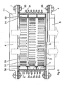
- the muffler 3 is arranged. It is a resonator muffler with slot-shaped openings 33 in the cover plate 31, which separate the resonator 32 against the flow channel 6.
- the silencer includes three successively arranged in the flow direction resonator chambers, each with different numbers of slots.
- the chambers may be covered by separate cover plates or by one or more common cover plates.
- the upper chamber is exemplified by its own Cover plate covered, while the two lower chambers are under a common cover plate.
- the individual chambers which can also be arranged alongside one another along the circumference, are subdivided by wall parts 35. Radially outside the chambers are limited by rear wall parts 34. When arranged on the circumference chambers these are separated from each other by corresponding, parallel to the axis used wall parts.
- the slots are aligned substantially in the flow direction and have a length I which is at least three times greater than the width b. Since the flow is not homogeneous in one direction, the individual slots can also be arranged at small angles to each other to better match the flow pattern. Depending on the course of the flow, the slots can also be curved. The depth t of the slots can be realized, for example, over the thickness of the cover plate. All three sizes (length, width and depth of the slots), as well as the number of slots per chamber and the dimensions of the chambers, have a direct impact on the damping capacity of the muffler.
- the muffler 3 is designed as a self-supporting unit.
- a step is integrated, which fits for fixing the muffler to the compensator in a corresponding recess in the mounting flange 22.
- the compensator element is used together with the muffler between the compressor outlet and the motor-side air line and screwed on both sides of the intended mounting flanges.
- the muffler may alternatively be clamped accordingly on the side of the connecting line 4 to the radiator.
- the silencer can project beyond the unloaded compensator element in and / or counter to the flow direction in the length into the inlet and outlet line.
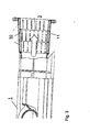
- Fig. 3 shows a second possibility of how the inventive silencer can be arranged in the region of the compressor outflow.
- the muffler is arranged as part of the spiral compressor housing, at the output in so-called outlet or discharge nozzle 11.
- outlet or discharge nozzle 11 By the arrangement of the muffler 3 in the area directly on the spiral outlet, the sound attenuation can be slightly improved.
- the sound contains many parts in this area, which can not propagate unattenuated towards the compressor outlet, but are attenuated by the muffler.
- the slightly smaller diameter of the flow channel in the outlet nozzle also provides for a slightly higher damping.
- the effective bandwidth of the generally narrow-band resonator and thus an effect in two or more frequency ranges can be achieved.
- the muffler in the outflow can also be made as a separate insert, which is used during assembly in a corresponding recess in the housing.
- inventive silencer with the substantially aligned in the flow direction slots is particularly well suited for the area of the compressor discharge, it can also be used in other areas of the flow channels, for example in the intake of the compressor or turbine side.
- the mode of operation of the resonator silencer according to the invention is explained below.
- the mass of the opening approximately corresponds to the mass and the volume of air in the chamber of the spring of a mass-spring system.
- the chamber volume is separated from the flow by the cover plate. If a flow passes the opening at great speed, part of the swinging air plug is sheared off by the flow. The oscillating air plug becomes smaller, resulting in a frequency shift. Further, the radial movement possibility of the plug is hindered by the vorbest moussede air such that additionally results in a reduced damping effect.
Landscapes
- Engineering & Computer Science (AREA)
- Chemical & Material Sciences (AREA)
- Combustion & Propulsion (AREA)
- Mechanical Engineering (AREA)
- General Engineering & Computer Science (AREA)
- Structures Of Non-Positive Displacement Pumps (AREA)
- Supercharger (AREA)
- Exhaust Silencers (AREA)
Description
Die Erfindung bezieht sich auf das Gebiet der Abgasturbolader für Brennkraftmaschinen. Sie betrifft einen Resonatorschalldämpfer gemäss dem Oberbegriff des Patentanspruchs 1. Sie betrifft ferner eine Brennkraftmaschine mit einem entsprechenden Resonatorschalldämpfer.The invention relates to the field of exhaust gas turbochargers for internal combustion engines. It relates to a resonator silencer according to the preamble of
Massgeblich für die Lärmemissionen eines Abgasturboladers für Brennkraftmaschinen ist der Verdichter. Insbesondere werden am druckseitigen Austritt des Verdichters hohe Lärmpegel in die luftführenden Leitungen eingeleitet, für deren Dämpfung es bislang keine zufriedenstellende Lösung gibt.Decisive for the noise emissions of an exhaust gas turbocharger for internal combustion engines is the compressor. In particular, high noise levels are introduced into the air-carrying lines at the pressure-side outlet of the compressor, for the damping there is so far no satisfactory solution.
Bei im Strömungskanal angeordneten Absorbern ergibt sich das Problem, dass durch die hohen Strömungsgeschwindigkeiten der komprimierten Luft das Absorbermaterial durch die Lochblechabdeckungen ausgeblasen wird. Durch Ablagerung des Materials in den meist nachfolgenden Kühlern können diese verstopft werden. Auch sind die auf mineralische Basis hergestellten Fasermaterialen in den nachfolgenden Motorenkomponenten der Brennkraftmaschinen unerwünscht.When arranged in the flow channel absorbers, the problem arises that the absorber material is blown through the perforated metal covers by the high flow rates of the compressed air. By depositing the material in most of the subsequent coolers, they can become clogged. Also, the fiber-based materials produced on a mineral basis are undesirable in the subsequent engine components of the internal combustion engines.
Auf dem Prinzip eines Helmholtz-Resonators beruhende Schalldämpfer bestehen aus einer oder mehren Kammern, welche mittels einem Blech mit darin eingelassenen Öffnungen abgedeckt werden. Die Luft in der Kammer dient den schwingenden Luftmassepfropfen in den Öffnungen als Feder. Die hohe Strömungsgeschwindigkeit der am Schalldämpfer vorbeigeführten komprimierten Luft führt jedoch dazu, dass ein erheblicher Teil der schwingenden Luftmasse abgeschert wird. Der schwingende Luftpfropfen wird kleiner. Dies führt zu Verstimmung der Auslegefrequenz und zum Nachlassen der Dämpfungswirkung. Herkömmliche Resonatorschalldämpfer sind demzufolge bei Strömungsgeschwindigkeiten des vorbeifliessenden Mediums von bis zu 100 m/s nicht ausreichend wirksam.Silencers based on the principle of a Helmholtz resonator consist of one or more chambers, which are covered by means of a metal sheet with openings embedded therein. The air in the chamber serves as a spring to the vibrating Luftmassepfropfen in the openings. However, the high flow rate of the compressed air passed to the muffler results in a significant portion of the oscillating air mass being sheared off. The swinging air plug gets smaller. This leads to detuning the Auslegefrequenz and to lessen the damping effect. Conventional resonator silencers are therefore not sufficiently effective at flow velocities of the flowing medium of up to 100 m / s.
Ein im Strömungskanal angeordneter, herkömmlicher Resonator, wie beispielsweise in
Der Erfindung liegt folglich die Aufgabe zugrunde, einen Schalldämpfer der eingangs genannten Art zu schaffen, welcher auch bei hohen Strömungsgeschwindigkeiten eine gute Dämpfungswirkung zeigt.The invention is therefore an object of the invention to provide a muffler of the type mentioned, which shows a good damping effect even at high flow velocities.
Erfindungsgemäss wird diese Aufgabe mit den Merkmalen des Patentanspruchs 1 gelöst.According to the invention, this object is achieved with the features of
Der Resonatorschalldämpfer weist mindestens eine Kammer auf, welche einen Strömungskanal oder Teile des Umfanges umschliesst. Die Kammer ist gegen den Strömungskanal hin durch ein Abdeckblech vollständig abgedeckt, wobei das Abdeckblech mehrere Öffnungen aufweist. Die Öffnungen des Abdeckblechs sind erfindungsgemäss als Schlitze ausgebildet, welche im wesentlichen in Strömungsrichtung ausgerichtet sind.The resonator muffler has at least one chamber, which encloses a flow channel or parts of the circumference. The chamber is completely covered against the flow channel through a cover plate, wherein the cover plate has a plurality of openings. The openings of the cover plate are according to the invention designed as slots, which are aligned substantially in the flow direction.
Aufgrund der Länge der Schlitze ist es der Strömung nicht möglich, den schwingenden Luftmassepfropfen in den Öffnungen auf der gesamten Länge gleichzeitig abzuscheren bzw. dessen Bewegungsmöglichkeit auf der gesamten Länge synchron einzuschränken. Die Dämpfungswirkung des erfindungsgemässen Schalldämpfers bleibt daher auch bei grosser Strömungsgeschwindigkeit weitgehend erhalten.Due to the length of the slots, it is not possible for the flow to simultaneously shear the oscillating plug of air mass in the openings along the entire length or to synchronously restrict its movement possibility over the entire length. The damping effect of the inventive muffler therefore remains largely preserved even at high flow rates.
Um eine optimale Dämpfwirkung zu erzielen, wird das Verhältnis der Summe der Öffnungsflächen zur gegen den Strömungskanal gerichteten Gesamtoberfläche einer Kammer zwischen 4% und 25%, insbesondere zwischen 6% und 14% gewählt. Bei zu kleinem respektive zu grossem Verhältnis nimmt die Wirkung ab.In order to achieve an optimum damping effect, the ratio of the sum of the opening areas to the total surface of a chamber directed against the flow channel is chosen to be between 4% and 25%, in particular between 6% and 14%. If the ratio is too small or too large, the effect will be less.
Die Länge der Schlitze in Strömungsrichtung wird wesentlich grösser als die Breite der Schlitze gewählt. Durch das Anbringen von unterschiedlich lang ausgebildeten Schlitzen im Abdeckblech wird Wirksamkeit des Dämpfers verbessert.The length of the slots in the flow direction is chosen to be substantially greater than the width of the slots. By attaching slots of different lengths formed in the cover plate effectiveness of the damper is improved.
Werden entlang des Strömungskanals mehrere, voneinander getrennte Kammern angeordnet, kann die Dämpfungswirkung auf einem breiteren Frequenzbereich abgestimmt werden. Hierfür werden die Anzahl, die Länge und die Gesamtsumme der Öffnungsflächen der Schlitze entsprechend variiert.If a plurality of separate chambers are arranged along the flow channel, the damping effect can be tuned to a wider frequency range. For this purpose, the number, the length and the total sum of the opening areas of the slots are varied accordingly.
Der auch bei hohen Strömungsgeschwindigkeiten wirksame erfindungsgemässe Schalldämpfer wird vorteilhafterweise zur Dämpfung des Verdichterlärmes eines Turboladers verwendet. Besonders im Bereich des Ladeluftauslasses, in dem erhebliche Lärmwerte und die genannt grossen Strömungsgeschwindigkeiten auftreten, kann damit eine wesentlicher Beitrag zur angestrebten Verringerung der Lärmemissionen der nachfolgenden luftführenden Komponenten erreicht werden.The inventive muffler which is effective even at high flow velocities is advantageously used for damping the compressor noise of a turbocharger. Particularly in the area of the charge air outlet, in which considerable noise values and the large flow velocities mentioned occur, a substantial contribution can be made to the desired reduction in the noise emissions of the subsequent air-guiding components.
Zum Einbau des vorliegenden Schalldämpfers eignet sich besonders der Kompensator, welcher die Verbindung von Verdichteraustrittsspirale und Motorkomponenten darstellt. Durch die Wahl des Kompensators als wesentlicher Einbauort ergibt sich auch die Möglichkeit der Nachrüstung bereits gelieferter bzw. in Betrieb stehender Brennkraftmaschinen.For installation of the present muffler, the compensator is particularly suitable, which represents the connection of the compressor outlet spiral and engine components. By choosing the compensator as an essential installation location, there is also the possibility of retrofitting already delivered or in operation internal combustion engines.
Ebenfalls günstig ist der Einbau des Schalldämpfers direkt in den Ausgang des spiralenförmigen Verdichtergehäuses. Aufgrund der Lage näher an der Lärmquelle und des etwas engeren Strömungskanals kann die Wirkung des Resonators noch zusätzlich verbessert werden.Also low is the installation of the muffler directly into the outlet of the spiral compressor housing. Due to the position closer to the noise source and the slightly narrower flow channel, the effect of the resonator can be further improved.
Weitere Vorteile ergeben sich aus den abhängigen Ansprüchen.Further advantages emerge from the dependent claims.
Im folgenden sind anhand der Figuren Ausführungsbeispiele des Einbaus des erfindungsgemässen Schalldämpfers sowie ein Ausführungsbeispiel des Aufbaus des Schalldämpfers schematisch dargestellt und näher erläutert. In allen Figuren sind gleichwirkende Elemente mit gleichen Bezugszeichen versehen. Es zeigen:
- Fig. 1
- eine schematische Darstellung des ladeluftseitigen Einbaus zwischen einem Turbolader und einer Brennkraftmaschine mit einem Kompensatorelement mit einem integrierten Resonatorschalldämpfer,
- Fig. 2
- einen Schnitt in Strömungsrichtung durch das Kompensatorelement und den integrierten Resonatorschalldämpfer nach
Fig.1 , wobei der Kompensator in der linken Hälfte der Figur in normalem und in der rechten Hälfte in leicht gestrecktem Zustand dargestellt ist, und - Fig. 3
- eine Teilschnittansicht auf ein spiralenförmiges Verdichtergehäuse mit einem integrierten Resonatorschalldämpfer in dem Spiralenaustritt.
- Fig. 1
- 1 is a schematic representation of the charge-air-side installation between a turbocharger and an internal combustion engine having a compensator element with an integrated resonator silencer;
- Fig. 2
- a section in the flow direction through the compensator and the integrated resonator silencer according to
Fig.1 , wherein the compensator in the left half of the figure is shown in the normal and in the right half in a slightly stretched state, and - Fig. 3
- a partial sectional view of a spiral-shaped compressor housing with an integrated resonator silencer in the spiral outlet.
Das Kompensatorelement, welches in
Im Innem des Kompensators ist erfindungsgemäss der Schalldämpfer 3 angeordnet. Es handelt sich um einen Resonatorschalldämpfer mit schlitzförmigen Öffnungen 33 in dem Abdeckblech 31, welches die Resonatorkammern 32 gegen den Strömungskanal 6 abtrennen. In der dargestellten Ausführungsform umfasst der Schalldämpfer drei in Strömungsrichtung nacheinander angeordnete Resonatorkammern mit jeweils unterschiedlich vielen Schlitzen. Die Kammern können durch separate Abdeckbleche oder aber durch ein oder mehrere gemeinsame Abdeckbleche abgedeckt sein. In der dargestellten Ausführungsform ist beispielhaft die obere Kammer durch ein eigenes Abdeckblech abgedeckt, während sich die beiden unteren Kammern unter einem gemeinsamen Abdeckblech befinden.In the interior of the compensator according to the invention, the
Die einzelnen Kammern, welche auch entlang dem Umfang nebeneinander angeordnet sein können, sind durch Wandteile 35 unterteilt. Radial aussen sind die Kammern durch Rückwandteile 34 begrenzt. Bei am Umfang angeordneten Kammern werden diese gegeneinander durch entsprechende, parallel zur Achse eingesetzte Wandteile abgetrennt.The individual chambers, which can also be arranged alongside one another along the circumference, are subdivided by wall parts 35. Radially outside the chambers are limited by
Die Schlitze sind im wesentlichen in Strömungsrichtung ausgerichtet und haben eine Länge I, welche mindestens dreimal grösser ist als die Breite b. Da die Strömung nicht homogen in eine Richtung verläuft, können die einzelnen Schlitze auch in kleinen Winkeln zueinander angeordnet sein, um dem Strömungsverlauf besser zu entsprechen. Je nach Strömungsverlauf können die Schlitze auch gebogen ausgebildet sein. Die Tiefe t der Schlitze kann beispielsweise über die Dicke des Abdeckbleches realisiert werden. Alle drei Grössen (Länge, Breite und Tiefe der Schlitze) haben, ebenso wie die Anzahl der Schlitze pro Kammer sowie die Abmessungen der Kammern, einen direkten Einfluss auf das Dämpfvermögen des Schalldämpfers.The slots are aligned substantially in the flow direction and have a length I which is at least three times greater than the width b. Since the flow is not homogeneous in one direction, the individual slots can also be arranged at small angles to each other to better match the flow pattern. Depending on the course of the flow, the slots can also be curved. The depth t of the slots can be realized, for example, over the thickness of the cover plate. All three sizes (length, width and depth of the slots), as well as the number of slots per chamber and the dimensions of the chambers, have a direct impact on the damping capacity of the muffler.
Der Schalldämpfer 3 ist als freitragende Einheit ausgebildet. In die stirnseitige Wand 36 ist ein Absatz integriert, welcher zur Befestigung des Schalldämpfers an dem Kompensatorelement in eine entsprechende Ausnehmung in dem Befestigungsflansch 22 passt. Beim Montieren wird somit zuerst der Schalldämpfer 3 und das Kompensatorelement 2 zusammengestellt. Anschliessend wird das Kompensatorelement mitsamt dem Schalldämpfer zwischen Verdichteraustritt und motorseitiger Luftleitung eingesetzt und beidseitig an den vorgesehenen Befestigungsflanschen festgeschraubt. Auf der Seite des Verdichteraustrittes wird dabei das Stirnwandteil 36 zwischen dem Befestigungsflansch 22 und dem Flansch des Verdichteraustrittes 11 festgeklemmt. Der Schalldämpfer kann alternativ auch auf der Seite der Verbindungsleitung 4 zum Kühler entsprechend festgeklemmt sein.The
Der Schalldämpfer kann das unbelastete Kompensatorelement in und/ oder entgegen der Strömungsrichtung in der Länge in die zu- und abführende Leitung überragen.The silencer can project beyond the unloaded compensator element in and / or counter to the flow direction in the length into the inlet and outlet line.
Obwohl sich der erfindungsgemässe Schalldämpfer mit den im wesentlichen in Strömungsrichtung ausgerichteten Schlitzen besonders gut für den Bereich des Verdichterabströmbereichs eignet, kann er auch in anderen Bereichen der Strömungskanäle eingesetzt werden, beispielsweise im Ansaugbereich des Verdichters oder auch turbinenseitig.Although the inventive silencer with the substantially aligned in the flow direction slots is particularly well suited for the area of the compressor discharge, it can also be used in other areas of the flow channels, for example in the intake of the compressor or turbine side.
Die Funktionsweise des erfindungsgemässen Resonatorschalldämpfers wird folgend erläutert. Bei einem herkömmlichen Helmholtz-Resonators mit einer kreisrunden Öffnung entspricht die Masse der Öffnung in etwa der Masse und das Luftvolumen in der Kammer der Feder eines Masse-Federsystems. Das Kammervolumen ist durch das Abdeckblech von der Strömung abgetrennt. Wenn nun eine Strömung mit grosser Geschwindigkeit an der Öffnung vorbeizieht wird ein Teil des schwingenden Luftpfropfens durch die Strömung abgeschert. Der schwingende Luftpfropfen wird kleiner, was zu einer Frequenzverschiebung führt. Weiter wird die radiale Bewegungsmöglichkeit des Pfropfens durch die vorbestreichende Luft derart behindert, dass sich zusätzlich eine reduzierte Dämpfungswirkung ergibt.The mode of operation of the resonator silencer according to the invention is explained below. In a conventional Helmholtz resonator with a circular opening, the mass of the opening approximately corresponds to the mass and the volume of air in the chamber of the spring of a mass-spring system. The chamber volume is separated from the flow by the cover plate. If a flow passes the opening at great speed, part of the swinging air plug is sheared off by the flow. The oscillating air plug becomes smaller, resulting in a frequency shift. Further, the radial movement possibility of the plug is hindered by the vorbestreichende air such that additionally results in a reduced damping effect.
Dieser Effekt wird bei dem erfindungsgemässen Schalldämpfer durch den Einsatz von länglichen Schlitzöffnungen beträchtlich reduziert. Aufgrund der Länge des Schlitzes ist es der Strömung nicht möglich den Massepfropfen auf der gesamten Länge gleichzeitig abzuscheren bzw. dessen Bewegungsmöglichkeit auf der gesamten Länge synchron einzuschränken.This effect is considerably reduced in the inventive muffler by the use of elongated slot openings. Due to the length of the slot, it is not possible for the flow to simultaneously shear off the ground plug over the entire length or to limit its movement possibility synchronously over the entire length.
- 11
- Verdichtercompressor
- 1111
- Verdichteraustritt, AbströmstutzenCompressor outlet, outlet connection
- 22
- Kompensatorelementcompensator
- 2121
- Kompensationselementcompensation element
- 22, 2322, 23
- Befestigungsflanschmounting flange
- 33
- Schalldämpfersilencer
- 3131
- AbdeckblechCover plate
- 3232
- Resonatorkammerresonator
- 3333
- Schlitzöffnungslot opening
- 3434
- KammerrückwandChamber rear wall
- 3535
- KammerunterteilungsstückChamber subdivision piece
- 3636
- SchalldämpferstirnwandSilencer end wall
- 44
- Verbindungsleitung zum KühlerConnecting line to the radiator
- 55
- Kühlercooler
- 66
- Strömungskanal, StrömungFlow channel, flow
- 77
- Befestigungsmittel, SchraubenFasteners, screws
- II
- Länge der SchlitzöffnungLength of the slot opening
- bb
- Breite der SchlitzöffnungWidth of the slot opening
- tt
- Tiefe der SchlitzöffnungDepth of slot opening
Claims (10)
- Resonator muffler (3) with at least one chamber (32) which at least partially surrounds a flow duct (6), the at least one chamber (32) being covered completely relative to the flow duct (6) by a cover plate (31), the cover plate (31) having a plurality of orifices arranged along the circumference of the flow duct (6), which orifices are designed as slots (33) oriented in the flow direction, the ratio of the length (1) to the width (b) of the slots (33) being higher than 3, characterized in that the slots (33) are designed at least partially with a different length.
- Resonator muffler according to Claim 1, characterized in that the ratio of the sum of the orifice areas (33) to the total area (31), directed toward the flow duct, of the respective chamber lies between 4% and 25%.
- Resonator muffler according to Claim 2, characterized in that the ratio of the sum of the orifice areas (33) to the total area (31), directed toward the flow duct, of the respective chamber lies between 6% and 14%.
- Resonator muffler according to one of Claims 1 to 3, characterized in that the muffler comprises a plurality of chambers (32) arranged in succession in the flow direction.
- Resonator muffler according to Claim 4, characterized in that the chambers are each covered by a separate cover plate.
- Resonator muffler according to either one of Claims 4 and 5, characterized in that the covers of the plurality of chambers (32) have in each case a different number of slots (33) per chamber.
- Internal combustion engine with at least one exhaust gas turbocharger, at least one flow-carrying element (2) in the region of the exhaust gas turbocharger comprising at least one resonator muffler (3) according to one of the preceding claims.
- Internal combustion engine according to Claim 7, characterized in that a compensator element (2) is provided in the region of the compressor outlet (11), and in that the muffler (3) is designed and is mountable for the most part as an integral part of the compensator element.
- Internal combustion engine according to either one of Claims 7 and 8, characterized in that a compensator element (2) is arranged between an outflow connection piece (11) at the compressor outlet and a connecting line (4) issuing into a charge-air cooler (5), and in that the muffler (3) projects beyond the compensator in and/or opposite to the flow direction, at least on one side, in such a way that the muffler projects into the connecting line and/or the outflow connection piece.
- Internal combustion engine according to Claim 9, characterized in that the exhaust gas turbocharger comprises a compressor (1) for compressing a gaseous medium, the compressor comprising a compressor housing with an orifice on the gas inlet side and an orifice on the gas outlet side, the orifice on the gas outlet side comprising an outflow connection piece (11) for fastening a flow-carrying element, and in that the resonator muffler (3) is arranged in the outflow connection piece of the compressor outlet.
Applications Claiming Priority (4)
| Application Number | Priority Date | Filing Date | Title |
|---|---|---|---|
| DE10339539A DE10339539A1 (en) | 2003-08-26 | 2003-08-26 | Resonance silencer for exhaust gas-driven turbocharger of vehicle, includes chamber covering sheet with openings formed as slots along flow direction |
| DE10339539 | 2003-08-26 | ||
| CH9512004 | 2004-06-04 | ||
| CH9512004 | 2004-06-04 |
Publications (3)
| Publication Number | Publication Date |
|---|---|
| EP1510667A2 EP1510667A2 (en) | 2005-03-02 |
| EP1510667A3 EP1510667A3 (en) | 2005-08-10 |
| EP1510667B1 true EP1510667B1 (en) | 2008-10-08 |
Family
ID=34105206
Family Applications (1)
| Application Number | Title | Priority Date | Filing Date |
|---|---|---|---|
| EP04405497A Active EP1510667B1 (en) | 2003-08-26 | 2004-08-05 | Silencer |
Country Status (6)
| Country | Link |
|---|---|
| EP (1) | EP1510667B1 (en) |
| JP (1) | JP2005069228A (en) |
| KR (1) | KR101126653B1 (en) |
| CN (1) | CN100538028C (en) |
| DE (1) | DE502004008190D1 (en) |
| DK (1) | DK1510667T3 (en) |
Families Citing this family (21)
| Publication number | Priority date | Publication date | Assignee | Title |
|---|---|---|---|---|
| DE102005053118A1 (en) * | 2005-11-08 | 2007-05-10 | Volkswagen Ag | Internal combustion engine with mechanical charge |
| JP2007192164A (en) * | 2006-01-20 | 2007-08-02 | Komatsu Ltd | Intake noise reduction device and working machine |
| EP1873364A1 (en) * | 2006-06-29 | 2008-01-02 | ABB Turbo Systems AG | Silencer |
| CN101165320B (en) * | 2006-10-18 | 2010-09-01 | 方建升 | Grating type harmonic wave sound absorber |
| DE102009051104A1 (en) * | 2009-10-28 | 2011-05-05 | Mann + Hummel Gmbh | centrifugal compressors |
| FR2955900B1 (en) * | 2010-02-01 | 2013-07-05 | Hutchinson | ACOUSTICAL ATTENUATION DEVICE FOR THE INTAKE LINE OF A THERMAL MOTOR, FLEXIBLE PIPE AND ADMISSION LINE INCORPORATING IT |
| DE102010020064B4 (en) * | 2010-05-11 | 2019-10-02 | Bayerische Motoren Werke Aktiengesellschaft | Silencer arrangement for a particular supercharged motor vehicle internal combustion engine |
| KR101748687B1 (en) * | 2010-08-11 | 2017-06-19 | 보르그워너 인코퍼레이티드 | Turbocharger |
| DE102011002869B4 (en) * | 2011-01-19 | 2014-08-07 | Siemens Aktiengesellschaft | reflection silencer |
| JP6008495B2 (en) * | 2011-12-16 | 2016-10-19 | 三菱重工業株式会社 | Exhaust turbine turbocharger |
| CN103291386A (en) * | 2013-06-14 | 2013-09-11 | 湖南天雁机械有限责任公司 | Turbocharger silencer |
| WO2016177430A1 (en) | 2015-05-07 | 2016-11-10 | Volvo Truck Corporation | A conduit connection assembly, a turbine inlet conduit, a turbo charger and a vehicle |
| CN106286045A (en) * | 2015-06-23 | 2017-01-04 | 华晨汽车集团控股有限公司 | Engine with supercharger noise reduction gas handling system |
| CN106468211A (en) * | 2015-08-18 | 2017-03-01 | 上海汽车集团股份有限公司 | Automobile, electromotor, the acoustic filter located at supercharger gas outlet and forming method |
| JP6629627B2 (en) * | 2016-02-22 | 2020-01-15 | 三菱重工業株式会社 | Noise reduction structure and supercharging device |
| CN106014720B (en) * | 2016-06-27 | 2018-10-12 | 江苏科技大学 | A kind of automatic frequency adjustment turbocharger air inlet composite muffler and its noise reduction method |
| WO2019076094A1 (en) * | 2017-10-17 | 2019-04-25 | 上海大创汽车技术有限公司 | Noise reduction device applicable to air intake ducting of automobile, air intake ducting of automobile, automobile, and noise reduction method |
| DE102019201504A1 (en) | 2019-02-06 | 2020-08-06 | Psa Automobiles Sa | Air duct for a motor vehicle and method for its manufacture |
| CN111058947B (en) * | 2020-01-09 | 2020-12-18 | 浙江特富发展股份有限公司 | Gas turbine exhaust utilization system |
| CN113915441B (en) * | 2021-10-14 | 2022-08-12 | 哈尔滨理工大学 | Ventilating duct silencer |
| GB2616609A (en) * | 2022-03-14 | 2023-09-20 | Dyson Technology Ltd | Noise attenuator |
Family Cites Families (13)
| Publication number | Priority date | Publication date | Assignee | Title |
|---|---|---|---|---|
| US2056608A (en) * | 1933-12-22 | 1936-10-06 | C F Burges Lab Inc | Silencer |
| US2124916A (en) * | 1937-06-14 | 1938-07-26 | Buffalo Pressed Steel Company | Muffler |
| US2233341A (en) * | 1938-07-27 | 1941-02-25 | Hayes Ind Inc | Muffler construction |
| US3415336A (en) * | 1966-11-14 | 1968-12-10 | Arvin Ind Inc | Resonator and method of making it |
| JPH068251Y2 (en) * | 1987-04-02 | 1994-03-02 | マツダ株式会社 | Exhaust silencer |
| DE4219249C2 (en) * | 1992-06-12 | 1994-03-31 | Kuehnle Kopp Kausch Ag | Radial compressor, especially a turbocharger |
| DE19504223A1 (en) * | 1995-02-09 | 1996-08-14 | Volkswagen Ag | Intake silencer for internal combustion engine |
| DE19611133A1 (en) * | 1996-03-21 | 1997-09-25 | Eberspaecher J | Muffler arrangement |
| JPH10318194A (en) * | 1997-05-19 | 1998-12-02 | Mitsui Eng & Shipbuild Co Ltd | Muffler for discharge noise of blower |
| DE19818874C2 (en) * | 1998-04-28 | 2001-06-07 | Man B & W Diesel As Kopenhagen | Reciprocating machine |
| DE19818873C2 (en) * | 1998-04-28 | 2001-07-05 | Man B & W Diesel Ag | Reciprocating internal combustion engine |
| GB0018620D0 (en) * | 2000-07-28 | 2000-09-13 | Draftex Ind Ltd | Noise attenuation arrangements for pressurised-gas conduits |
| DE10058479A1 (en) * | 2000-11-24 | 2002-05-29 | Mann & Hummel Filter | Wide band damper for induction tract of internal combustion engine has resonance chamber adjoining induction tract and filled with absorption material separated from duct section by barrier layer on partitioning wall |
-
2004
- 2004-08-05 EP EP04405497A patent/EP1510667B1/en active Active
- 2004-08-05 DE DE502004008190T patent/DE502004008190D1/en active Active
- 2004-08-05 DK DK04405497T patent/DK1510667T3/en active
- 2004-08-19 JP JP2004239538A patent/JP2005069228A/en active Pending
- 2004-08-24 KR KR1020040066690A patent/KR101126653B1/en active IP Right Grant
- 2004-08-26 CN CNB200410057928XA patent/CN100538028C/en active Active
Also Published As
| Publication number | Publication date |
|---|---|
| KR101126653B1 (en) | 2012-03-28 |
| DK1510667T3 (en) | 2009-02-09 |
| DE502004008190D1 (en) | 2008-11-20 |
| KR20050022360A (en) | 2005-03-07 |
| CN100538028C (en) | 2009-09-09 |
| EP1510667A2 (en) | 2005-03-02 |
| EP1510667A3 (en) | 2005-08-10 |
| JP2005069228A (en) | 2005-03-17 |
| CN1590725A (en) | 2005-03-09 |
Similar Documents
| Publication | Publication Date | Title |
|---|---|---|
| EP1510667B1 (en) | Silencer | |
| DE69727502T2 (en) | SILENCER WITH PARTITIONS | |
| DE19818873C2 (en) | Reciprocating internal combustion engine | |
| DE60122688T2 (en) | MUFFLER WITH ONE OR MORE POROUS BODIES | |
| EP1715189B1 (en) | Noise attenuator designed and meant for a compressor | |
| EP1352172B1 (en) | Silencer with a plurality of resonance chambers | |
| EP1213538B1 (en) | Exhaust gas system with Helmholtz resonator | |
| EP0740080B1 (en) | Filter-silencer | |
| DE2247361A1 (en) | SILENCER FOR THE AIR INTAKE SYSTEM | |
| WO1999047807A1 (en) | Air induction system for an internal combustion engine | |
| EP0791135A1 (en) | Exhaust silencer | |
| EP2000637B1 (en) | Exhaust silencer | |
| EP0713046B1 (en) | Silencing arrangement for pipelines | |
| DE19743446A1 (en) | Exhaust silencing system for internal combustion engine | |
| EP1798390B1 (en) | Engine exhaust apparatus | |
| EP1321639B2 (en) | Silencer arrangement | |
| DE19818874C2 (en) | Reciprocating machine | |
| DE2309571A1 (en) | EXHAUST SILENCER FOR TWO-STROKE ENGINES | |
| EP1873364A1 (en) | Silencer | |
| DE19520157A1 (en) | Motor vehicle exhaust silencer with choke flap | |
| DE10339539A1 (en) | Resonance silencer for exhaust gas-driven turbocharger of vehicle, includes chamber covering sheet with openings formed as slots along flow direction | |
| EP0674747B1 (en) | Silencer | |
| EP1400662A1 (en) | Silencer with resonator | |
| DE10103739B4 (en) | silencer | |
| DE10131475B4 (en) | exhaust silencer |
Legal Events
| Date | Code | Title | Description |
|---|---|---|---|
| PUAI | Public reference made under article 153(3) epc to a published international application that has entered the european phase |
Free format text: ORIGINAL CODE: 0009012 |
|
| AK | Designated contracting states |
Kind code of ref document: A2 Designated state(s): AT BE BG CH CY CZ DE DK EE ES FI FR GB GR HU IE IT LI LU MC NL PL PT RO SE SI SK TR |
|
| AX | Request for extension of the european patent |
Extension state: AL HR LT LV MK |
|
| PUAL | Search report despatched |
Free format text: ORIGINAL CODE: 0009013 |
|
| AK | Designated contracting states |
Kind code of ref document: A3 Designated state(s): AT BE BG CH CY CZ DE DK EE ES FI FR GB GR HU IE IT LI LU MC NL PL PT RO SE SI SK TR |
|
| AX | Request for extension of the european patent |
Extension state: AL HR LT LV MK |
|
| 17P | Request for examination filed |
Effective date: 20051202 |
|
| AKX | Designation fees paid |
Designated state(s): DE DK FI GB IT |
|
| 17Q | First examination report despatched |
Effective date: 20070820 |
|
| GRAP | Despatch of communication of intention to grant a patent |
Free format text: ORIGINAL CODE: EPIDOSNIGR1 |
|
| GRAS | Grant fee paid |
Free format text: ORIGINAL CODE: EPIDOSNIGR3 |
|
| GRAA | (expected) grant |
Free format text: ORIGINAL CODE: 0009210 |
|
| AK | Designated contracting states |
Kind code of ref document: B1 Designated state(s): DE DK FI GB IT |
|
| REG | Reference to a national code |
Ref country code: GB Ref legal event code: FG4D Free format text: NOT ENGLISH |
|
| REF | Corresponds to: |
Ref document number: 502004008190 Country of ref document: DE Date of ref document: 20081120 Kind code of ref document: P |
|
| REG | Reference to a national code |
Ref country code: DK Ref legal event code: T3 |
|
| PLBE | No opposition filed within time limit |
Free format text: ORIGINAL CODE: 0009261 |
|
| STAA | Information on the status of an ep patent application or granted ep patent |
Free format text: STATUS: NO OPPOSITION FILED WITHIN TIME LIMIT |
|
| 26N | No opposition filed |
Effective date: 20090709 |
|
| REG | Reference to a national code |
Ref country code: DE Ref legal event code: R081 Ref document number: 502004008190 Country of ref document: DE Owner name: TURBO SYSTEMS SWITZERLAND LTD., CH Free format text: FORMER OWNER: ABB TURBO SYSTEMS AG, BADEN, CH Ref country code: DE Ref legal event code: R082 Ref document number: 502004008190 Country of ref document: DE Representative=s name: ZIMMERMANN & PARTNER PATENTANWAELTE MBB, DE Ref country code: DE Ref legal event code: R081 Ref document number: 502004008190 Country of ref document: DE Owner name: ABB SCHWEIZ AG, CH Free format text: FORMER OWNER: ABB TURBO SYSTEMS AG, BADEN, CH |
|
| REG | Reference to a national code |
Ref country code: FI Ref legal event code: PCE Owner name: ABB SWITZERLAND LTD. |
|
| REG | Reference to a national code |
Ref country code: GB Ref legal event code: 732E Free format text: REGISTERED BETWEEN 20210225 AND 20210303 |
|
| REG | Reference to a national code |
Ref country code: GB Ref legal event code: 732E Free format text: REGISTERED BETWEEN 20210304 AND 20210310 |
|
| REG | Reference to a national code |
Ref country code: GB Ref legal event code: 732E Free format text: REGISTERED BETWEEN 20220922 AND 20220928 |
|
| REG | Reference to a national code |
Ref country code: DE Ref legal event code: R081 Ref document number: 502004008190 Country of ref document: DE Owner name: TURBO SYSTEMS SWITZERLAND LTD., CH Free format text: FORMER OWNER: ABB SCHWEIZ AG, BADEN, CH |
|
| PGFP | Annual fee paid to national office [announced via postgrant information from national office to epo] |
Ref country code: DK Payment date: 20220824 Year of fee payment: 19 |
|
| PGFP | Annual fee paid to national office [announced via postgrant information from national office to epo] |
Ref country code: IT Payment date: 20230825 Year of fee payment: 20 Ref country code: GB Payment date: 20230824 Year of fee payment: 20 Ref country code: FI Payment date: 20230821 Year of fee payment: 20 |
|
| PGFP | Annual fee paid to national office [announced via postgrant information from national office to epo] |
Ref country code: DE Payment date: 20230821 Year of fee payment: 20 |
|
| REG | Reference to a national code |
Ref country code: DK Ref legal event code: EBP Effective date: 20230831 |