EP1510458A1 - Lift thruster for levitating a platform - Google Patents
Lift thruster for levitating a platform Download PDFInfo
- Publication number
- EP1510458A1 EP1510458A1 EP03292101A EP03292101A EP1510458A1 EP 1510458 A1 EP1510458 A1 EP 1510458A1 EP 03292101 A EP03292101 A EP 03292101A EP 03292101 A EP03292101 A EP 03292101A EP 1510458 A1 EP1510458 A1 EP 1510458A1
- Authority
- EP
- European Patent Office
- Prior art keywords
- armature
- weight
- assembly
- generating device
- lift
- Prior art date
- Legal status (The legal status is an assumption and is not a legal conclusion. Google has not performed a legal analysis and makes no representation as to the accuracy of the status listed.)
- Withdrawn
Links
- 239000000725 suspension Substances 0.000 claims 7
- 238000006243 chemical reaction Methods 0.000 abstract description 10
- 230000033001 locomotion Effects 0.000 description 20
- 230000009471 action Effects 0.000 description 14
- 230000026058 directional locomotion Effects 0.000 description 13
- 230000001133 acceleration Effects 0.000 description 10
- 238000000034 method Methods 0.000 description 6
- 230000000284 resting effect Effects 0.000 description 5
- 239000007789 gas Substances 0.000 description 2
- 230000005484 gravity Effects 0.000 description 2
- 230000003116 impacting effect Effects 0.000 description 2
- 238000009987 spinning Methods 0.000 description 2
- 230000005540 biological transmission Effects 0.000 description 1
- 239000004020 conductor Substances 0.000 description 1
- 230000008878 coupling Effects 0.000 description 1
- 238000010168 coupling process Methods 0.000 description 1
- 238000005859 coupling reaction Methods 0.000 description 1
- 238000010304 firing Methods 0.000 description 1
- 238000005339 levitation Methods 0.000 description 1
- 239000007788 liquid Substances 0.000 description 1
- 238000005461 lubrication Methods 0.000 description 1
- 230000005012 migration Effects 0.000 description 1
- 238000013508 migration Methods 0.000 description 1
- 238000012986 modification Methods 0.000 description 1
- 230000004048 modification Effects 0.000 description 1
- 230000008569 process Effects 0.000 description 1
- 230000002459 sustained effect Effects 0.000 description 1
Images


Classifications
-
- F—MECHANICAL ENGINEERING; LIGHTING; HEATING; WEAPONS; BLASTING
- F03—MACHINES OR ENGINES FOR LIQUIDS; WIND, SPRING, OR WEIGHT MOTORS; PRODUCING MECHANICAL POWER OR A REACTIVE PROPULSIVE THRUST, NOT OTHERWISE PROVIDED FOR
- F03H—PRODUCING A REACTIVE PROPULSIVE THRUST, NOT OTHERWISE PROVIDED FOR
- F03H99/00—Subject matter not provided for in other groups of this subclass
-
- B—PERFORMING OPERATIONS; TRANSPORTING
- B64—AIRCRAFT; AVIATION; COSMONAUTICS
- B64C—AEROPLANES; HELICOPTERS
- B64C39/00—Aircraft not otherwise provided for
- B64C39/003—Aircraft not otherwise provided for with wings, paddle wheels, bladed wheels, moving or rotating in relation to the fuselage
-
- B—PERFORMING OPERATIONS; TRANSPORTING
- B64—AIRCRAFT; AVIATION; COSMONAUTICS
- B64G—COSMONAUTICS; VEHICLES OR EQUIPMENT THEREFOR
- B64G1/00—Cosmonautic vehicles
- B64G1/22—Parts of, or equipment specially adapted for fitting in or to, cosmonautic vehicles
- B64G1/40—Arrangements or adaptations of propulsion systems
- B64G1/409—Unconventional spacecraft propulsion systems
-
- F—MECHANICAL ENGINEERING; LIGHTING; HEATING; WEAPONS; BLASTING
- F03—MACHINES OR ENGINES FOR LIQUIDS; WIND, SPRING, OR WEIGHT MOTORS; PRODUCING MECHANICAL POWER OR A REACTIVE PROPULSIVE THRUST, NOT OTHERWISE PROVIDED FOR
- F03G—SPRING, WEIGHT, INERTIA OR LIKE MOTORS; MECHANICAL-POWER PRODUCING DEVICES OR MECHANISMS, NOT OTHERWISE PROVIDED FOR OR USING ENERGY SOURCES NOT OTHERWISE PROVIDED FOR
- F03G7/00—Mechanical-power-producing mechanisms, not otherwise provided for or using energy sources not otherwise provided for
- F03G7/10—Alleged perpetua mobilia
- F03G7/104—Alleged perpetua mobilia continuously converting gravity into usable power
- F03G7/107—Alleged perpetua mobilia continuously converting gravity into usable power using an unbalance for increasing torque or saving energy
Definitions
- This invention relates to a unit for generating lift for lifting a platform and for steering the platform, more specifically to a lift-generating unit that uses recoil, impact, and centripetal forces, to lift and steer a platform upon which the unit is attached.
- Flight has been known for centuries. Birds have long used it as a means for migration, hunting and seeking shelter. Humans have been annoyed with air travel. However, it has only been in our recent past that humans have produced machines capable of sustained flight, e.g., airplanes, helicopters, rocket ships and Hovercraft. These flying machines generate lift using rotors, propellers, compressed gas or compressed liquid. For example, lift in hovering vehicles is supplied by compressing air from below the vehicle using a rapidly rotating rotor and allowing the compressed air to generate lifting of the vehicle. Such a device has the shortcoming in that it cannot generate lift in a vacuum, e.g., outer space.
- a vacuum e.g., outer space.
- Machines that do generate lift in vacuums typically expel gases through a port located in the bottom of the vehicle. There is a need for other methods of generating lift in a vacuum. Additionally, there is always a need for finding new ways for man to fly.
- the lift-generating unit of the present invention uses a rotating armature with a movable plunger mounted thereon. Lift is produced by coupling the forces generated by rotating the armature while simultaneously moving the plunger during rotation.
- recoil force generated by moving the plunger, using centripetal force, generated by rotation of the armature, to provide lift.
- impact force generated by moving the plunger, in conjunction with centripetal force, generated by rotating the armature is used to provide lift.
- the difference between recoil and impact forces is essentially the position of the plunger and the direction in which the plunger is moved during rotation of the armature.
- an armature which rotates about a horizontal axis, is used to provide the centripetal force while a movable plunger mounted on the armature is employed to provide the recoil/impact forces.
- the armature rotates in a vertical plane.
- a frame with a horizontally oriented axis provides the horizontal axis and support about which the armature rotates.
- horizontal directional movement is achieved by mechanically rotating the armature on its vertical plane using a pinion that would allow the armature to direct the force at any horizontal angle when needed. If these armatures were rotating in a horizontal plane, it would require a counter-rotating mass to avoid keeping the entire unit from spinning. However, this can be so adapted if desired.
- the plunger In order to provide recoil force, the plunger is moved in a downwardly vertical direction during rotation. To provide a recoil force during the top half of rotation, the plunger is moved from a position away from the axis to a position near the axis. To provide recoil force during the bottom half of the rotation, the plunger is moved from a position near the axis to a position away from the axis.
- the top half of rotation being between 270° and 90°, assuming a clockwise rotation with 360°/0° at the top; and the bottom half of rotation being between about 90° and 270°, assuming clockwise rotation and 360°/0° at the top.
- the recoil force can be generated either during only one half of the rotation or during both halves of the rotation.
- the plunger should always be positioned away from the axis during the bottom half of rotation and near the axis during the top half of rotation. It will be understood that the actual distance between the axis and the plunger will vary and that near the axis does not mean next to the axis.
- the plunger In order to provide impact force, the plunger is moved in an upwardly vertical direction during rotation. To provide an impact force during the top half of rotation, the plunger is moved from a position near the axis to a position away from the axis. To provide an impact force during the bottom half of rotation, the plunger is moved from a position away from the axis to a position near the axis.
- the top half and bottom half of rotation being as defined above.
- the impact force can be generated either during only one half of the rotation or during both halves of the rotation.
- the plunger should always be positioned near the axis during the bottom half of rotation and away from the axis during the top half of rotation.
- plungers are equiangular about the axis and are positioned in a common vertical plane.
- the present invention is directed to a lift-generating unit having a plunger for generating recoil/impact energy which uses centripetal force to generate horizontal and vertical lift.
- This first embodiment of the present invention can be characterized as an electromagnet and reciprocating ball horizontal mover. As shown in FIG.1, this embodiment utilizes an electromechanical arrangement for the recoil device. To accomplish this, recoil generating devices are disposed at opposite ends of a revolving armature. For levitation, each recoil generating device is activated when it is in the upward position of the armature rotation to generate downward force, causing an equal and opposite lifting force. By continuously firing recoil devices, each time one of the recoil devices is in the upward position, lift can be maintained.
- each recoil device comprises an electromechanical arrangement.
- Each recoil device comprises an electromagnet 1 and a ball 2 having magnetic primability.
- Each electromagnet 1 is placed inside a tube 3 and each tube 3 is mounted on a rotating armature 4.
- the electromagnet 1 is positioned near the center of the tube 3, in relation to tube length, so as to face away from the center of rotation and have limited movement inside tube 3.
- the movement of electromagnet 1 is restricted by electromagnet holder bracket 5 that also provides electrical current when needed.
- the electromagnet 1 receives electrical power from electrical conductor 14 through electrical contact 13 located in serrated area 15.
- the ball 2 When the unit is inactive, the ball 2 can rest on a rubber stopper 6 mounted on retaining plate 7 secured to the outward end of tube 3. However, depending on the position of the rotating armature 4 when not in motion, the ball 2 can rest on a magnetic protection pad 8 located on the outermost surface of the electromagnet 1. The electromagnet 1 and retaining plate thus 7 restrict the movement of ball 2.
- Armature drive motor 9 supplies power to rotate armature 4 in a vertical plane.
- Armature direction changing motor 10 is connected to shaft 11 located in stationary portion 16.
- Stationary portion 16 is mounted on base 17 and is capable of movement through the use of wheels 18.
- Shaft 11 is in turn connected to gears 12 to provide horizontal directional movement of armature support 19.
- the spinning of armature 4 supplies the required centripetal force. Assuming that each ball 2 weighs 200 pounds, the armature 4 can be rotated at a speed in which each of the balls 2 displays an apparent weight of 4,500 pounds, due to the artificial gravity generated by centripetal acceleration. These numbers are, of course, used as an example.
- a direction can be selected for movement of the entire unit by a control system (not shown in).
- a control system (not shown in).
- an electronic sensor or photoelectric cell (not shown) energizes electromagnet 1 which in turn attracts ball 2 towards the axis of rotation, thus generating a recoil force.
- the entire unit is forced to move in the direction of the incoming ball 2 by this recoil force.
- artificial gravity generated by centripetal force begins to slow ball 2 down to a stop.
- Ball 2 will then reverse direction, and travel back to rest against retaining plate 7 once again.
- the foregoing process is repeated each rotation and, due to the high rate of revolution of armature 4, lift can be maintained.
- the amount of power directed to electromagnet 1 the amount of lift can be controlled.
- Electromagnet 1 has limited movement inside tube 3 which helps to absorb the impact of ball 2.
- a second preferred embodiment of the invention is referred to as a screw weight reciprocator horizontal mover.
- the screw weight reciprocator horizontal mover uses a mechanical arrangement for recoil action to generate directional movement. It achieves this by rapidly propelling a mass towards the center of rotation of a revolving armature causing the axis of rotation to move in the direction of the incoming mass due to recoil reaction. Centripetal force created by the revolving armature counteracts the mass before it impacts the axis of rotation, which is necessary because impact would impede recoil reaction.
- FIG. 3 illustrates the configuration of the screw weight reciprocator horizontal mover.
- Rotating armature 4 is comprised of screw shaft 21 and parallel rods 22.
- Parallel rods 22 are mounted so as to allow for movement of reciprocating weight 20 along the axis of rotating armature 4.
- Reciprocating weight 20 is also center taped completely through by screw shaft 21, screw shaft 21 being driven by screw shaft drive motor 23 allowing for controlled movement of reciprocating weight 20.
- Reciprocating weight 20 incorporates disjoint system 24 allowing reciprocating weight 20 to move along parallel rods 22 uninhibited by screw shaft 21.
- a third preferred embodiment of the present invention is referred to as a gear weight reciprocator horizontal mover.
- the gear weight reciprocator horizontal mover primarily utilizes recoil action to achieve directional movement, however some impact action is also capable. This is achieved by rapidly propelling a mass towards the center of rotation of a revolving armature causing the axis of rotation to move in the direction of the incoming mass due to recoil reaction. Centripetal force created by the revolving armature counteracts the mass before it impacts the axis of rotation, which is necessary because impact would impede recoil reaction.
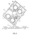
- FIG. 5 illustrates the configuration of the gear weight reciprocator horizontal mover.
- Rotating armature 4 is comprised of rack 25 and guide rods 26.
- Gear weights 27 are mounted along rack 25, two on each side of rack 25, the teeth of each gear weight 27 are able to intersect with corresponding gaps along rack 25 to allow for controlled movement of gear weight 27 along the length of rack 25.
- Gear weight 27 is connected to gear weight motor set 28 which are in turn mounted about guide rods 26.
- Gear weight motor set 28 allows for controlled movement of gear weight 27 along rack 25.
- gear weight 27 and gear weight motor set 28 will reach their travel limits and rest on gear weight travel stopper 29a.
- Disjoint system 24 is activated locking gear weight motor set 28 onto guide rods 26. The unit is now on stand-by.
- gear weight motor set 28 is activated at a point during the armatures rotation corresponding to the selected direction of travel.
- Gear weight motor set 28 rotates gear weight 27 thus rapidly propelling gear weight 27 and gear weight motor set 28 towards the axis of rotation. The entire unit moves in the direction of the incoming weight due to recoil forces.
- gear weight travel stopper 29b is positioned to prevent gear weight 27 and gear weight motor set 28 from impacting the axis of rotation, in the event centripetal forces are not strong enough to impede and fully propel gear weight 27 and gear weight motor set 28 to their rest against gear weight travel stopper 29a. This method of operation is once again repeated until the desired travel location is reached.
- a fourth preferred embodiment of the present invention is referred to as a lateral solenoid reciprocating horizontal mover.
- the lateral solenoid reciprocating horizontal mover uses recoil and impact action to achieve directional movement. This is achieved by rapidly propelling a mass towards the center of rotation of a revolving armature causing the axis of rotation to move in the direction of the incoming mass due to recoil reaction. Centripetal force created by the revolving armature counteracts the mass before it impacts the axis of rotation, which is necessary because impact would impede recoil reaction.
- FIG. 7 illustraterates the configuration of the lateral solenoid reciprocating horizontal mover.
- Rotating armature 4 is comprised of parallel guide rails 30.
- Solenoid plunger 31 is mounted on and able to move freely about parallel guide rails 30 through the use of electrical contact rollers 32.
- Solenoid plunger 31 receives electrical energy from electrical contact rollers 32 through solenoid coil 33, and allows for controlled movement of solenoid plunger 31.
- the range of movement of solenoid plunger 31 is limited by solenoid housing 34.
- solenoid plunger 31 will reach its travel limit and rest on rubber stopper 35a. The unit is now on stand-by. When the machine operator selects a direction of travel, electrical energy activates solenoid plunger 31 at a point during the armatures rotation corresponding to the selected direction of travel. Solenoid plunger 31 is thus rapidly propelled towards the axis of rotation. The entire unit moves in the direction of the incoming weight due to recoil forces.
- solenoid plunger 31 impacts the axis of rotation, the supply of electrical energy is discontinued. Centripetal force now impedes the movement of solenoid plunger 31, bringing solenoid plunger 31 to a stop, reversing its direction, and once again resting it against rubber stopper 35a. Rubber stopper 35b is positioned to prevent solenoid plunger 31 from impacting the axis of rotation, in the event centripetal forces are not strong enough to impede and fully propel solenoid plunger 31 to its rest against rubber stopper 35a.
- Horizontal directional movement of armature support 19 is controlled by piston and crossbar 36, rather than by shaft 11 and gears 12 as in previous embodiments. This method of operation is continuously repeated until travel destination is reached.
- a fifth preferred embodiment of the present invention is referred to as an impact reciprocating horizontal mover.
- the impact reciprocating horizontal mover primarily uses impact action to achieve directional movement. This is accomplished by rotating an armature to strike a stationary mass thereby causing directional movement in the direction of the impact. Centripetal force created by the revolving armature can be varied to control impact action.
- FIG. 9 illustrates the configuration of the impact reciprocating horizontal mover.
- Rotating armature 4 is comprised of geomantic collapsible truss 37 and truss wheel 38, all of which are housed within furring 39 for lubrication purposes.
- pinion bolt 40 On the outer circumferential surface of furring 39 lies pinion bolt 40. Pinion bolt 40 acts to control the movement of retractable ramp 41 once impact action is achieved.
- hydraulic piston 42 releases tension in spring 43 enabling retractable ramp 41 to fully retract and position its elongated end outside furring 39.
- Armature drive motor 9 then begins to establish centripetal acceleration of rotating armature 4, and truss 37 will extend and allow truss wheel 38 to make contact with the inner wall of furring 39.
- the unit is now on stand-by.
- positioning gear 44 rotates gear 45 to aim retractable ramp 41 in a direction corresponding to the selected travel direction. Hydraulic piston 42 and spring 43 now increase force against the narrowed end of retractable ramp 41, allowing the elongated end of retractable ramp 41 to enter within the inner wall of furring 39.
- Rotating truss wheel 38 impacts retractable weight 41 on impact drive line 46.
- Impact drive line 46 is propelled into impact point 47 mounted on furring 39. The entire unit moves in the direction of the propelled retractable ramp 41 due to impact action. Additional impact force is supplied by weight 48, which is mounted on and travels along truss 37.
- a sixth preferred embodiment of the present invention is referred to as an external impact ball reciprocator horizontal mover.
- the external impact ball reciprocator horizontal mover uses recoil action to achieve directional movement. Recoil action is achieved by rapidly propelling a mass towards the center of rotation of a revolving armature causing the axis of rotation to move in the direction of the incoming mass due to recoil reaction. Centripetal force created by the revolving armature counteracts the mass before it impacts the axis of rotation, which is necessary because impact would impede recoil reaction.
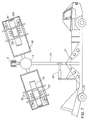
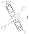
- FIG. 10 illustrates the configuration of the external impact ball reciprocator horizontal mover.
- Platform extension 49 supports outer tube 50 on rotating armature 4.
- Outer tube 50 houses piston-like unit 51, which in turn houses ball 52, the configuration of such allowing for reciprocation of ball 52 within piston-like unit 51.
- Piston-like unit 51 is similarly able to move within outer tube 50.
- An opening exists in outer tube 50 located on the outer portion of rotating armature 4. This opening allows for solenoid coil 53 and plunger 54 to make contact with ball 52.
- Air vent 55 exists on the inner side of outer tube 50 allowing for air to escape during reciprocation of piston-like unit 51.
- This unit is also equipped with counter rotating platform 56 which rotates in the opposite direction of rotating armature 4 in order to stabilize the unit.
- Rotating platform 56 is comprised of extension 57 and fixed ball 58. Similar to the centripetal acceleration established by rotating armature 4, rotating platform 56 establishes its own centripetal acceleration of fixed ball 58 in the rotation directional opposite to that of rotating armature 4. The force generated by rotating armature 4 is thus counteracted and neutralized by that of rotating platform 56 enabling the unit to remain in a stable state. Counter-rotation is accomplished with gear box or transmission unit 59.
- a seventh preferred embodiment of the present invention is referred to as a fixed electromagnetic horizontal mover.
- the fixed electromagnetic horizontal mover utilizes recoil and impact action to achieve directional movement. It achieves this by rapidly propelling a mass towards the center of rotation of a revolving armature causing the axis of rotation to move in the direction of the incoming mass due to recoil reaction. Similarly, impact action is generated when the mass, when returned to its starting position, strikes against the outer circumference of rotation. Centripetal force created by the revolving armature can be varied to control recoil and impact action.
- FIG. 12 illustrates the configuration of the fixed electromagnetic horizontal mover.
- Rotating armature 4 is comprised of electromagnet holder bracket 63, located on the inner circumferential surface of rotating armature 4, and outer bracket 64, located on the outer circumferential surface of rotating armature 4.
- electromagnet holding bracket 63 Mounted upon electromagnet holding bracket 63 is electromagnet 1.
- Plunger 54 and plunger stopper 65 are mounted upon outer bracket 64.
- Armature drive motor 9 establishes centripetal acceleration of rotating armature 4, causing plunger 54 to reach its travel limit and rest against plunger stopper 65. The unit is now on stand-by.
- electromagnet 1 When the operator selects the desired direction of travel, electromagnet 1 is activated and attracts plunger 54 toward the axis of rotation causing corresponding directional movement due to recoil action.
- Centripetal force created by revolving armature 4 counteracts the movement of plunger 54 and causes plunger 54 to reverse its direction of travel before it impacts plunger stopper 65. Impact force is generated creating directional movement as plunger 54 strikes plunger stopper 65 as plunger 54 once again reaches its travel limit.
- Recoil force and impact force must be coordinated to occur during the same degree of rotating armature 4, assuming a 360° rotation, in order to maximize directional movement.
- Counter-rotating secondary dish 66 is mounted on armature support 19 and is rotated in a direction opposite to that of rotating armature 4 in order to stabilize the system.
Abstract
Description
- This invention relates to a unit for generating lift for lifting a platform and for steering the platform, more specifically to a lift-generating unit that uses recoil, impact, and centripetal forces, to lift and steer a platform upon which the unit is attached.
- Flight has been known for centuries. Birds have long used it as a means for migration, hunting and seeking shelter. Humans have been fascinated with air travel. However, it has only been in our recent past that humans have produced machines capable of sustained flight, e.g., airplanes, helicopters, rocket ships and Hovercraft. These flying machines generate lift using rotors, propellers, compressed gas or compressed liquid. For example, lift in hovering vehicles is supplied by compressing air from below the vehicle using a rapidly rotating rotor and allowing the compressed air to generate lifting of the vehicle. Such a device has the shortcoming in that it cannot generate lift in a vacuum, e.g., outer space.
- Machines that do generate lift in vacuums typically expel gases through a port located in the bottom of the vehicle. There is a need for other methods of generating lift in a vacuum. Additionally, there is always a need for finding new ways for man to fly.
- This invention satisfies the above needs. A novel lift-generating unit for generating lift in a vacuum has now been discovered. The lift-generating unit of the present invention uses a rotating armature with a movable plunger mounted thereon. Lift is produced by coupling the forces generated by rotating the armature while simultaneously moving the plunger during rotation. In one embodiment, recoil force, generated by moving the plunger, using centripetal force, generated by rotation of the armature, to provide lift. In another embodiment of the invention, impact force, generated by moving the plunger, in conjunction with centripetal force, generated by rotating the armature is used to provide lift. The difference between recoil and impact forces is essentially the position of the plunger and the direction in which the plunger is moved during rotation of the armature.
- In both embodiments, an armature, which rotates about a horizontal axis, is used to provide the centripetal force while a movable plunger mounted on the armature is employed to provide the recoil/impact forces. The armature rotates in a vertical plane. A frame with a horizontally oriented axis provides the horizontal axis and support about which the armature rotates.
- In both embodiments, horizontal directional movement is achieved by mechanically rotating the armature on its vertical plane using a pinion that would allow the armature to direct the force at any horizontal angle when needed. If these armatures were rotating in a horizontal plane, it would require a counter-rotating mass to avoid keeping the entire unit from spinning. However, this can be so adapted if desired.
- In order to provide recoil force, the plunger is moved in a downwardly vertical direction during rotation. To provide a recoil force during the top half of rotation, the plunger is moved from a position away from the axis to a position near the axis. To provide recoil force during the bottom half of the rotation, the plunger is moved from a position near the axis to a position away from the axis. The top half of rotation being between 270° and 90°, assuming a clockwise rotation with 360°/0° at the top; and the bottom half of rotation being between about 90° and 270°, assuming clockwise rotation and 360°/0° at the top.
- The recoil force can be generated either during only one half of the rotation or during both halves of the rotation. In any event, the plunger should always be positioned away from the axis during the bottom half of rotation and near the axis during the top half of rotation. It will be understood that the actual distance between the axis and the plunger will vary and that near the axis does not mean next to the axis.
- In order to provide impact force, the plunger is moved in an upwardly vertical direction during rotation. To provide an impact force during the top half of rotation, the plunger is moved from a position near the axis to a position away from the axis. To provide an impact force during the bottom half of rotation, the plunger is moved from a position away from the axis to a position near the axis. The top half and bottom half of rotation being as defined above.
- The impact force can be generated either during only one half of the rotation or during both halves of the rotation. In any event, the plunger should always be positioned near the axis during the bottom half of rotation and away from the axis during the top half of rotation.
- It is preferred that more than one plunger can be employed in the present invention. Where a plurality of plungers are employed, the plungers are equiangular about the axis and are positioned in a common vertical plane. Preferably, there are an even number of plungers and, more preferably, either 2 or 4 plungers.
- These and other features, aspects and advantages of the present invention may be understood with reference to the following drawings wherein:
- FIG. 1 shows a sectional side view of a preferred embodiment of the invention;
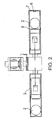
- FIG. 2 shows a bottom view of the preferred embodiment in FIG. 1;
- FIG. 3 shows a sectional view of another preferred embodiment on the invention;
- FIG. 4 shows a top view of the preferred embodiment in FIG. 3;
- FIG. 5 shows a sectional view of another preferred embodiment on the invention;
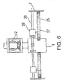
- FIG. 6 shows a top view of the preferred embodiment in FIG. 5;
- FIG. 7 shows a sectional view of another preferred embodiment of the present invention;
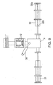
- FIG. 8 shows a bottom view of the preferred embodiment in FIG. 7;
- FIG. 9 shows a sectional view of another preferred embodiment of the present invention;
- FIG. 10 shows a sectional side view of another preferred embodiment of the present invention;
- FIG. 11 shows a top view of the preferred embodiment in FIG 10;
- FIG. 12 shows a side view of another preferred embodiment of the present invention;
- FIG. 13 shows a top view of the preferred embodiment in FIG 12.
-
- The present invention is directed to a lift-generating unit having a plunger for generating recoil/impact energy which uses centripetal force to generate horizontal and vertical lift.
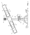
- This first embodiment of the present invention can be characterized as an electromagnet and reciprocating ball horizontal mover. As shown in FIG.1, this embodiment utilizes an electromechanical arrangement for the recoil device. To accomplish this, recoil generating devices are disposed at opposite ends of a revolving armature. For levitation, each recoil generating device is activated when it is in the upward position of the armature rotation to generate downward force, causing an equal and opposite lifting force. By continuously firing recoil devices, each time one of the recoil devices is in the upward position, lift can be maintained.
- Referring to FIG. 1, there is shown an inventive lift-providing unit in which the recoil device comprises an electromechanical arrangement. Each recoil device comprises an
electromagnet 1 and aball 2 having magnetic primability. Eachelectromagnet 1 is placed inside a tube 3 and each tube 3 is mounted on arotating armature 4. Theelectromagnet 1 is positioned near the center of the tube 3, in relation to tube length, so as to face away from the center of rotation and have limited movement inside tube 3. The movement ofelectromagnet 1 is restricted by electromagnet holder bracket 5 that also provides electrical current when needed. Theelectromagnet 1 receives electrical power fromelectrical conductor 14 throughelectrical contact 13 located inserrated area 15. - When the unit is inactive, the
ball 2 can rest on arubber stopper 6 mounted on retainingplate 7 secured to the outward end of tube 3. However, depending on the position of therotating armature 4 when not in motion, theball 2 can rest on amagnetic protection pad 8 located on the outermost surface of theelectromagnet 1. Theelectromagnet 1 and retaining plate thus 7 restrict the movement ofball 2. - Armature drive
motor 9 supplies power to rotatearmature 4 in a vertical plane. Armaturedirection changing motor 10 is connected toshaft 11 located instationary portion 16.Stationary portion 16 is mounted onbase 17 and is capable of movement through the use ofwheels 18.Shaft 11 is in turn connected togears 12 to provide horizontal directional movement ofarmature support 19. The spinning ofarmature 4 supplies the required centripetal force. Assuming that eachball 2 weighs 200 pounds, thearmature 4 can be rotated at a speed in which each of theballs 2 displays an apparent weight of 4,500 pounds, due to the artificial gravity generated by centripetal acceleration. These numbers are, of course, used as an example. - Once centripetal acceleration is established by rotation of
armature 4 byarmature drive motor 9,electromagnet 1 andball 2 each reach their respective travel limits inside tube 3. At this point,ball 2 is positioned at a distance away fromelectromagnet 1 and is resting against retainingplate 7 by centripetal force. The unit is now on stand-by. - A direction can be selected for movement of the entire unit by a control system (not shown in). When rotating
armature 4 is in a position corresponding to the selected direction, an electronic sensor or photoelectric cell (not shown) energizeselectromagnet 1 which in turn attractsball 2 towards the axis of rotation, thus generating a recoil force. The entire unit is forced to move in the direction of theincoming ball 2 by this recoil force. Asball 2 is moving towards the axis of rotation, artificial gravity generated by centripetal force begins to slowball 2 down to a stop.Ball 2 will then reverse direction, and travel back to rest against retainingplate 7 once again. The foregoing process is repeated each rotation and, due to the high rate of revolution ofarmature 4, lift can be maintained. By controlling the amount of power directed toelectromagnet 1, the amount of lift can be controlled. - Inadvertent impact of
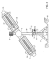
ball 2 againstelectromagnet 1 will not greatly impede or counteract recoil energy.Electromagnet 1 has limited movement inside tube 3 which helps to absorb the impact ofball 2. - A second preferred embodiment of the invention is referred to as a screw weight reciprocator horizontal mover. The screw weight reciprocator horizontal mover uses a mechanical arrangement for recoil action to generate directional movement. It achieves this by rapidly propelling a mass towards the center of rotation of a revolving armature causing the axis of rotation to move in the direction of the incoming mass due to recoil reaction. Centripetal force created by the revolving armature counteracts the mass before it impacts the axis of rotation, which is necessary because impact would impede recoil reaction.
- FIG. 3 illustrates the configuration of the screw weight reciprocator horizontal mover. Rotating
armature 4 is comprised ofscrew shaft 21 andparallel rods 22.Parallel rods 22 are mounted so as to allow for movement of reciprocatingweight 20 along the axis ofrotating armature 4. Reciprocatingweight 20 is also center taped completely through byscrew shaft 21,screw shaft 21 being driven by screwshaft drive motor 23 allowing for controlled movement of reciprocatingweight 20. Reciprocatingweight 20 incorporatesdisjoint system 24 allowing reciprocatingweight 20 to move alongparallel rods 22 uninhibited byscrew shaft 21. - Once
armature drive motor 9 establishes centripetal acceleration ofrotating armature 4, reciprocatingweight 20 will reach its travel limit and rest on retainingplate 7.Disjoint system 24 is activated locking reciprocatingweight 20 ontoscrew shaft 21. The unit is now on stand-by. When the machine operator selects a direction of travel, screw-shaft drive motor 23 is activated at a point during the armatures rotation corresponding to the selected direction of travel. Screwshaft drive motor 23 rotates screwshaft 21 thus rapidly propelling reciprocatingweight 20 towards the axis of rotation. The entire unit moves in the direction of the incoming weight due to recoil forces. - Before reciprocating
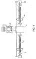
weight 20 impacts the axis of rotation,disjoint system 24 is deactivated, releasing reciprocatingweight 20 fromscrew shaft 21. Centripetal force now impedes the movement of reciprocatingweight 20, bringing reciprocatingweight 20 to a stop, reversing its direction, and once again resting it against retainingplate 7. This method of operation is repeated again until the desired travel location is reached. - A third preferred embodiment of the present invention is referred to as a gear weight reciprocator horizontal mover. The gear weight reciprocator horizontal mover primarily utilizes recoil action to achieve directional movement, however some impact action is also capable. This is achieved by rapidly propelling a mass towards the center of rotation of a revolving armature causing the axis of rotation to move in the direction of the incoming mass due to recoil reaction. Centripetal force created by the revolving armature counteracts the mass before it impacts the axis of rotation, which is necessary because impact would impede recoil reaction.
- FIG. 5 illustrates the configuration of the gear weight reciprocator horizontal mover. Rotating
armature 4 is comprised ofrack 25 and guiderods 26. Fourgear weights 27 are mounted alongrack 25, two on each side ofrack 25, the teeth of eachgear weight 27 are able to intersect with corresponding gaps alongrack 25 to allow for controlled movement ofgear weight 27 along the length ofrack 25.Gear weight 27 is connected to gear weight motor set 28 which are in turn mounted aboutguide rods 26. Gear weight motor set 28 allows for controlled movement ofgear weight 27 alongrack 25. - Once
armature drive motor 9 establishes centripetal acceleration ofrotating armature 4,gear weight 27 and gear weight motor set 28 will reach their travel limits and rest on gearweight travel stopper 29a.Disjoint system 24 is activated locking gear weight motor set 28 ontoguide rods 26. The unit is now on stand-by. When the machine operator selects a direction of travel, gear weight motor set 28 is activated at a point during the armatures rotation corresponding to the selected direction of travel. Gear weight motor set 28 rotatesgear weight 27 thus rapidly propellinggear weight 27 and gear weight motor set 28 towards the axis of rotation. The entire unit moves in the direction of the incoming weight due to recoil forces. - Before
gear weight 27 and gear weight motor set 28 impact the axis of rotation,disjoint system 24 is deactivated, releasing gear weight motor set 28 fromguide rods 26. Centripetal force now impedes the movement ofgear weight 27 and gear weight motor set 28, bringinggear weight 27 and gear weight motor set 28 to a stop, reversing their direction, and once again resting them against gearweight travel stopper 29a. Gearweight travel stopper 29b is positioned to preventgear weight 27 and gear weight motor set 28 from impacting the axis of rotation, in the event centripetal forces are not strong enough to impede and fully propelgear weight 27 and gear weight motor set 28 to their rest against gearweight travel stopper 29a. This method of operation is once again repeated until the desired travel location is reached. - A fourth preferred embodiment of the present invention is referred to as a lateral solenoid reciprocating horizontal mover. The lateral solenoid reciprocating horizontal mover uses recoil and impact action to achieve directional movement. This is achieved by rapidly propelling a mass towards the center of rotation of a revolving armature causing the axis of rotation to move in the direction of the incoming mass due to recoil reaction. Centripetal force created by the revolving armature counteracts the mass before it impacts the axis of rotation, which is necessary because impact would impede recoil reaction.
- FIG. 7 .illustrates the configuration of the lateral solenoid reciprocating horizontal mover. Rotating
armature 4 is comprised of parallel guide rails 30.Solenoid plunger 31 is mounted on and able to move freely aboutparallel guide rails 30 through the use ofelectrical contact rollers 32.Solenoid plunger 31 receives electrical energy fromelectrical contact rollers 32 throughsolenoid coil 33, and allows for controlled movement ofsolenoid plunger 31. The range of movement ofsolenoid plunger 31 is limited bysolenoid housing 34. - Once
armature drive motor 9 establishes centripetal acceleration ofrotating armature 4,solenoid plunger 31 will reach its travel limit and rest onrubber stopper 35a. The unit is now on stand-by. When the machine operator selects a direction of travel, electrical energy activatessolenoid plunger 31 at a point during the armatures rotation corresponding to the selected direction of travel.Solenoid plunger 31 is thus rapidly propelled towards the axis of rotation. The entire unit moves in the direction of the incoming weight due to recoil forces. - Before
solenoid plunger 31 impacts the axis of rotation, the supply of electrical energy is discontinued. Centripetal force now impedes the movement ofsolenoid plunger 31, bringingsolenoid plunger 31 to a stop, reversing its direction, and once again resting it againstrubber stopper 35a.Rubber stopper 35b is positioned to preventsolenoid plunger 31 from impacting the axis of rotation, in the event centripetal forces are not strong enough to impede and fully propelsolenoid plunger 31 to its rest againstrubber stopper 35a. Horizontal directional movement ofarmature support 19 is controlled by piston andcrossbar 36, rather than byshaft 11 and gears 12 as in previous embodiments. This method of operation is continuously repeated until travel destination is reached. - A fifth preferred embodiment of the present invention is referred to as an impact reciprocating horizontal mover. The impact reciprocating horizontal mover primarily uses impact action to achieve directional movement. This is accomplished by rotating an armature to strike a stationary mass thereby causing directional movement in the direction of the impact. Centripetal force created by the revolving armature can be varied to control impact action.
- FIG. 9 illustrates the configuration of the impact reciprocating horizontal mover. Rotating
armature 4 is comprised of geomanticcollapsible truss 37 andtruss wheel 38, all of which are housed within furring 39 for lubrication purposes. On the outer circumferential surface of furring 39 liespinion bolt 40.Pinion bolt 40 acts to control the movement ofretractable ramp 41 once impact action is achieved. - When operation is desired to begin,
hydraulic piston 42 releases tension inspring 43 enablingretractable ramp 41 to fully retract and position its elongated end outsidefurring 39. Armature drivemotor 9 then begins to establish centripetal acceleration ofrotating armature 4, andtruss 37 will extend and allowtruss wheel 38 to make contact with the inner wall offurring 39. The unit is now on stand-by. When the machine Operator selects a direction of travel,positioning gear 44 rotatesgear 45 to aimretractable ramp 41 in a direction corresponding to the selected travel direction.Hydraulic piston 42 andspring 43 now increase force against the narrowed end ofretractable ramp 41, allowing the elongated end ofretractable ramp 41 to enter within the inner wall offurring 39. Rotatingtruss wheel 38 impactsretractable weight 41 onimpact drive line 46.Impact drive line 46 is propelled intoimpact point 47 mounted onfurring 39. The entire unit moves in the direction of the propelledretractable ramp 41 due to impact action. Additional impact force is supplied byweight 48, which is mounted on and travels alongtruss 37. - A sixth preferred embodiment of the present invention is referred to as an external impact ball reciprocator horizontal mover. The external impact ball reciprocator horizontal mover uses recoil action to achieve directional movement. Recoil action is achieved by rapidly propelling a mass towards the center of rotation of a revolving armature causing the axis of rotation to move in the direction of the incoming mass due to recoil reaction. Centripetal force created by the revolving armature counteracts the mass before it impacts the axis of rotation, which is necessary because impact would impede recoil reaction.
- FIG. 10 illustrates the configuration of the external impact ball reciprocator horizontal mover.
Platform extension 49 supportsouter tube 50 on rotatingarmature 4.Outer tube 50 houses piston-like unit 51, which inturn houses ball 52, the configuration of such allowing for reciprocation ofball 52 within piston-like unit 51. Piston-like unit 51 is similarly able to move withinouter tube 50. An opening exists inouter tube 50 located on the outer portion ofrotating armature 4. This opening allows forsolenoid coil 53 andplunger 54 to make contact withball 52.Air vent 55 exists on the inner side ofouter tube 50 allowing for air to escape during reciprocation of piston-like unit 51. - This unit is also equipped with counter rotating
platform 56 which rotates in the opposite direction ofrotating armature 4 in order to stabilize the unit. Rotatingplatform 56 is comprised ofextension 57 and fixedball 58. Similar to the centripetal acceleration established by rotatingarmature 4, rotatingplatform 56 establishes its own centripetal acceleration of fixedball 58 in the rotation directional opposite to that ofrotating armature 4. The force generated by rotatingarmature 4 is thus counteracted and neutralized by that of rotatingplatform 56 enabling the unit to remain in a stable state. Counter-rotation is accomplished with gear box ortransmission unit 59. - Once
armature drive motor 9 establishes centripetal acceleration ofrotating armature 4, piston-like unit 51 andball 52 will reach their travel limits insideouter tube 50. The unit is now on stand-by. When the machine operator selects a direction of travel,solenoid coil 53 is energized at a point during the armatures rotation corresponding to the selected direction of travel.Solenoid coil 53 causes plunger 54 to strikeball 52, thus rapidly propellingball 52 inward towards the axis of rotation.Ball 52 then strikes piston-like unit 51, causing piston-like unit 51 along with attachedsolenoid coil 53 andplunger 54 to also be propelled inward. The entire unit moves in the direction of the incoming weight due to recoil forces. - At a point before piston-
like unit 51 impacts the axis of rotation and beforeball 52 strikesimpact protection pad 60, centripetal force will impede the movement of piston-like unit 51 andball 52, bringing piston-like unit 51 andball 52 to a stop, reversing their direction, resting piston-like unit 51 against retainingplate 61 andball 52 againstplunger 54.Plunger retaining plate 62 restricts the movement ofplunger 54 in a similar manner. This method of operation is once again repeated until the desired travel location is reached. - A seventh preferred embodiment of the present invention is referred to as a fixed electromagnetic horizontal mover. The fixed electromagnetic horizontal mover utilizes recoil and impact action to achieve directional movement. It achieves this by rapidly propelling a mass towards the center of rotation of a revolving armature causing the axis of rotation to move in the direction of the incoming mass due to recoil reaction. Similarly, impact action is generated when the mass, when returned to its starting position, strikes against the outer circumference of rotation. Centripetal force created by the revolving armature can be varied to control recoil and impact action.
- FIG. 12 illustrates the configuration of the fixed electromagnetic horizontal mover. Rotating
armature 4 is comprised ofelectromagnet holder bracket 63, located on the inner circumferential surface ofrotating armature 4, andouter bracket 64, located on the outer circumferential surface ofrotating armature 4. Mounted uponelectromagnet holding bracket 63 iselectromagnet 1.Plunger 54 andplunger stopper 65 are mounted uponouter bracket 64. - Armature drive
motor 9 establishes centripetal acceleration ofrotating armature 4, causingplunger 54 to reach its travel limit and rest againstplunger stopper 65. The unit is now on stand-by. When the operator selects the desired direction of travel,electromagnet 1 is activated and attractsplunger 54 toward the axis of rotation causing corresponding directional movement due to recoil action. Centripetal force created by revolvingarmature 4 counteracts the movement ofplunger 54 and causesplunger 54 to reverse its direction of travel before it impactsplunger stopper 65. Impact force is generated creating directional movement asplunger 54strikes plunger stopper 65 asplunger 54 once again reaches its travel limit. Recoil force and impact force must be coordinated to occur during the same degree ofrotating armature 4, assuming a 360° rotation, in order to maximize directional movement. Counter-rotatingsecondary dish 66 is mounted onarmature support 19 and is rotated in a direction opposite to that ofrotating armature 4 in order to stabilize the system. - It will be understood that claims are intended to cover all changes and modifications of the preferred embodiments of the invention herein chosen for the purpose of illustration which do not constitute a departure from the spirit and scope of the invention.
Claims (15)
- A lift-providing unit comprising two weight units, at least one of which is capable of generating a recoil force, said two weight units being disposed at opposite ends of a rotating armature.
- The lift-providing unit of Claim 1 comprising an armature assembly mounted in a suspension housing to be rotatable around a center axis and a drive unit for applying a rotating force to said armature assembly to generate a centripetal force,
said armature assembly comprising an armature having a first recoil generating device disposed at a first armature end and a second recoil generating device disposed at an opposite second armature end;
said first recoil generating device and said second recoil generating device each comprising:a ball slidably mounted between a retaining plate and an electromagnet,said electromagnet capable of attracting said ball against said electromagnet and maintaining said ball in an attracted position until said electromagnet is de-energized, anda control device for selectively energizing andde-energizing each of said electromagnet. - A vehicle comprising a platform attached to the lift-providing unit of Claim 1.
- The lift-providing unit of Claim 1 wherein said control device includes a timing circuit and a sensing device for registering each rotation of said armature.
- The lift-providing unit of Claim 1 comprising an armature assembly mounted in a suspension housing to be rotatable around a center axis and a drive unit for applying a rotating force to said armature assembly to generate a centripetal force,
said armature assembly comprising an armature having a first reciprocating weight assembly disposed at a first armature end and a second reciprocating weight assembly disposed at an opposite second armature end;
said first reciprocating weight assembly and said second reciprocating weight assembly each comprising:a reciprocating weight slidably mounted between a retaining plate and a lower base plate on at least one screw shaft passing through a corresponding fenestration in said reciprocating weight,a screw shaft drive motor capable of rotating said screw shaft to retract said reciprocating weight against said lower base plate and maintaining said reciprocating weight against said lower base plate until said screw shaft drive motor is de-energized, anda control device for selectively energizing said screw shaft drive motor. - The lift-providing unit of Claim 1 comprising an armature assembly mounted in a suspension housing to be rotatable around a center axis and a drive unit for applying a rotating force to said armature assembly to generate a centripetal force,
said armature assembly comprising a rack and guide rods, said armature assembly further comprising an armature having a first reciprocating gear weight assembly disposed at a first armature end and a second reciprocating gear weight assembly disposed at an opposite second armature end;
said first reciprocating gear weight assembly and said second reciprocating gear weight assembly each comprising:a reciprocating gear weight slidably mounted between an upper gear weight travel stopper and a lower gear weight travel stopper on at least one rack and guide rods,a gear weight motor set capable of rotating said reciprocating gear weight to retract against said lower gear weight travel stopper and maintaining said reciprocating gear weight against said lower gear weight travel stopper until said gear weight motor set is de-energized, anda control device for selectively energizing said gear weight motor set. - The lift-providing unit of Claim 1 comprising an armature assembly mounted in a suspension housing to be rotatable around a center axis and a drive unit for applying a rotating force to said armature assembly to generate a centripetal force,
said armature assembly comprising an armature having a first recoil generating device disposed at a first armature end and a second recoil generating device disposed at an opposite second armature end;
said first recoil generating device and said second recoil generating device each comprising:a solenoid plunger slidably mounted between an upper rubber stopper and a lower rubber stopper inside a solenoid housing,an electrical contact roller attached to said solenoid plunger wherein said electrical contact roller energizes and de-energizes said solenoid plunger,said electrical contact roller capable of attracting said solenoid plunger against said lower rubber stopper and maintaining said solenoid plunger in an attracted position until said solenoid plunger is de-energized, anda control device for selectively energizing and de-energizing each of said electromagnet. - The lift-providing unit of Claim 1 comprising an armature assembly mounted in a suspension housing to be rotatable around a center axis and a drive unit for applying a rotating force to said armature assembly to generate a centripetal force,
said armature assembly comprising an armature having a first recoil generating device disposed at a first armature end and a second recoil generating device disposed at an opposite second armature end;
said first recoil generating device and said second recoil generating device each comprising:a ball slidably mounted within a piston-like unit between a plunger and an impact protection pad,said plunger comprising a solenoid coil,said piston-like unit being slidably mounted within an outer tube,said solenoid coil capable of energizing said plunger to propel said ball against said impact protection pad, anda control device for selectively energizing and de-energizing each of said solenoid coil. - The lift-providing unit of Claim 8 comprising a counter rotating platform which rotates in the opposite direction of said armature assembly, and
said counter rotating platform comprising an extension and a fixed ball. - A lift-providing unit comprising two weight units, at least one of which is capable of generating an impact force, said two weight units being disposed at opposite ends of a rotating armature.
- The lift-providing unit of Claim 10 comprising an armature assembly and a furring wherein said armature assembly is mounted in a suspension housing to be rotatable around a center axis and a drive unit for applying a rotating force to said armature assembly to generate a centripetal force, said armature assembly comprising an armature having a first impact generating device disposed at a first armature end and a second impact generating device disposed at an opposite second armature end,
said furring comprising a retractable ramp wherein said retractable ramp further comprises:an elongated end comprising an impact drive line,a narrowed end comprising a hydraulic piston;said first impact generating device and said second impact generating device each comprising:a geomantic collapsible truss,a truss wheel mounted on an upper surface of said geomantic collapsible truss,a weight slidably mounted on said geomantic collapsible truss, andsaid truss wheel being capable of striking said impact drive line. - A vehicle comprising a platform attached to the lift-providing unit of Claim 10.
- The lift-providing unit of Claim 10 wherein said armature assembly and said furring are mounted concentrically within a gear.
- The lift-providing unit of Claim 10 wherein said platform comprises a positioning gear mounted on said platform wherein said positioning gear rotates said gear.
- The lift-providing unit of Claim 1 comprising an armature assembly and a counter-rotating secondary dish mounted in a suspension housing to be rotatable around a center axis and a drive unit for applying a rotating force to said armature assembly to generate a centripetal force,
said armature assembly comprising an armature having a first energy generating device disposed at a first armature end and a second energy generating device disposed at an opposite second armature end;
said first energy generating device and said second energy generating device each comprising:a plunger slidably mounted between a plunger stopper and an electromagnet,said electromagnet capable of attracting said plunger toward said electromagnet and maintaining said plunger in an attracted position until said electromagnet is de-energized, anda control device for selectively energizing and de-energizing each of said electromagnet.
Priority Applications (4)
| Application Number | Priority Date | Filing Date | Title |
|---|---|---|---|
| US10/196,976 US20040011924A1 (en) | 2002-07-17 | 2002-07-17 | Lift-providing unit for levitating a platform |
| EP03292101A EP1510458A1 (en) | 2002-07-17 | 2003-08-26 | Lift thruster for levitating a platform |
| JP2003305287A JP2005080345A (en) | 2002-07-17 | 2003-08-28 | Lift generator |
| CA002441505A CA2441505A1 (en) | 2002-07-17 | 2003-09-18 | Lift-providing unit for levitating a platform |
Applications Claiming Priority (4)
| Application Number | Priority Date | Filing Date | Title |
|---|---|---|---|
| US10/196,976 US20040011924A1 (en) | 2002-07-17 | 2002-07-17 | Lift-providing unit for levitating a platform |
| EP03292101A EP1510458A1 (en) | 2002-07-17 | 2003-08-26 | Lift thruster for levitating a platform |
| JP2003305287A JP2005080345A (en) | 2002-07-17 | 2003-08-28 | Lift generator |
| CA002441505A CA2441505A1 (en) | 2002-07-17 | 2003-09-18 | Lift-providing unit for levitating a platform |
Publications (1)
| Publication Number | Publication Date |
|---|---|
| EP1510458A1 true EP1510458A1 (en) | 2005-03-02 |
Family
ID=34623825
Family Applications (1)
| Application Number | Title | Priority Date | Filing Date |
|---|---|---|---|
| EP03292101A Withdrawn EP1510458A1 (en) | 2002-07-17 | 2003-08-26 | Lift thruster for levitating a platform |
Country Status (4)
| Country | Link |
|---|---|
| US (1) | US20040011924A1 (en) |
| EP (1) | EP1510458A1 (en) |
| JP (1) | JP2005080345A (en) |
| CA (1) | CA2441505A1 (en) |
Cited By (2)
| Publication number | Priority date | Publication date | Assignee | Title |
|---|---|---|---|---|
| CN103195676A (en) * | 2013-03-12 | 2013-07-10 | 潘汉祥 | Energy transformation output system |
| CN110789746A (en) * | 2019-10-25 | 2020-02-14 | 西安航天动力试验技术研究所 | L-shaped mounting rack for light high-strength rail control cabin |
Families Citing this family (11)
| Publication number | Priority date | Publication date | Assignee | Title |
|---|---|---|---|---|
| JP2005227745A (en) * | 2004-01-14 | 2005-08-25 | Seiko Epson Corp | Liquid crystal display device and electronic apparatus |
| PL392181A1 (en) * | 2010-08-19 | 2012-02-27 | Centrum Badawczo-Rozwojowe Epar Spółka Z Ograniczoną Odpowiedzialnością | Method of the kinetic energy storage and the rotor device for storage and dissipation of kinetic energy |
| CN102510168B (en) * | 2011-12-02 | 2013-05-22 | 潘汉祥 | Torque output system |
| WO2014139043A1 (en) * | 2013-03-12 | 2014-09-18 | Pan Hanxiang | Energy conversion output system |
| RU2576854C2 (en) * | 2014-05-14 | 2016-03-10 | Геннадий Петрович Какуша | Aircraft with power unit |
| US10753348B2 (en) * | 2015-01-05 | 2020-08-25 | David V. Bolger | Apparatuses and systems for converting fluid energy to mechanical motion |
| US20180009551A1 (en) * | 2016-07-08 | 2018-01-11 | Mark Joseph Skowronski | Impulse momentum propulsion apparatus and method |
| IT201700030825A1 (en) * | 2017-03-21 | 2018-09-21 | Pierangelo Bressan | TRAIN |
| FR3131282A1 (en) * | 2021-12-28 | 2023-06-30 | Warpa (World Advance Research Project Agency) | Impulse propulsion system |
| US20240035458A1 (en) * | 2022-08-01 | 2024-02-01 | Cristina Nania | Method and Apparatus for Accelerating a Vehicle in a Gravitational Field |
| CN116215896B (en) * | 2022-12-30 | 2023-08-18 | 中国科学院空间应用工程与技术中心 | Rotary platform and operation box for online cabinet |
Citations (6)
| Publication number | Priority date | Publication date | Assignee | Title |
|---|---|---|---|---|
| GB2273549A (en) * | 1992-12-21 | 1994-06-22 | Tan Thiam Chye Nelson | Motion energy converter |
| DE4411259A1 (en) * | 1994-03-31 | 1994-10-13 | Roland Kruk | Drive for accelerating and manoeuvring spacecraft |
| US5782134A (en) * | 1994-12-14 | 1998-07-21 | Booden; James D. | Electromagnetically actuated thrust generator |
| JPH11107905A (en) * | 1997-10-07 | 1999-04-20 | Takeshi Suzuki | Centrifugal force propulsion device |
| US6109123A (en) * | 1998-09-15 | 2000-08-29 | Baskis; Paul T. | Rotational inertial motor |
| EP1213477A1 (en) * | 1996-05-24 | 2002-06-12 | Jury Bronislavovich Ekhin | Method for converting the rotation of a solid body into linear traction force according to a directional unbalance process, and devices for realising the same |
Family Cites Families (4)
| Publication number | Priority date | Publication date | Assignee | Title |
|---|---|---|---|---|
| US2886976A (en) * | 1956-07-13 | 1959-05-19 | Norman L Dean | System for converting rotary motion into unidirectional motion |
| US3653269A (en) * | 1970-05-15 | 1972-04-04 | Richard E Foster | Converting rotary motion into unidirectional motion |
| CA1335239C (en) * | 1989-08-09 | 1995-04-18 | Mortimer S. Delroy | Gyrostat propulsion system |
| US5156058A (en) * | 1990-10-12 | 1992-10-20 | Bristow Jr Theodore R | Method and apparatus for converting rotary motion to lineal motion |
-
2002
- 2002-07-17 US US10/196,976 patent/US20040011924A1/en not_active Abandoned
-
2003
- 2003-08-26 EP EP03292101A patent/EP1510458A1/en not_active Withdrawn
- 2003-08-28 JP JP2003305287A patent/JP2005080345A/en active Pending
- 2003-09-18 CA CA002441505A patent/CA2441505A1/en not_active Abandoned
Patent Citations (6)
| Publication number | Priority date | Publication date | Assignee | Title |
|---|---|---|---|---|
| GB2273549A (en) * | 1992-12-21 | 1994-06-22 | Tan Thiam Chye Nelson | Motion energy converter |
| DE4411259A1 (en) * | 1994-03-31 | 1994-10-13 | Roland Kruk | Drive for accelerating and manoeuvring spacecraft |
| US5782134A (en) * | 1994-12-14 | 1998-07-21 | Booden; James D. | Electromagnetically actuated thrust generator |
| EP1213477A1 (en) * | 1996-05-24 | 2002-06-12 | Jury Bronislavovich Ekhin | Method for converting the rotation of a solid body into linear traction force according to a directional unbalance process, and devices for realising the same |
| JPH11107905A (en) * | 1997-10-07 | 1999-04-20 | Takeshi Suzuki | Centrifugal force propulsion device |
| US6109123A (en) * | 1998-09-15 | 2000-08-29 | Baskis; Paul T. | Rotational inertial motor |
Non-Patent Citations (2)
| Title |
|---|
| JERRY POURNELLE: ""THE DEAN DRIVE and other Reactionless Drives", 1 April 2000 (2000-04-01), XP002267714, Retrieved from the Internet <URL:http://www.jerrypournelle.com/sciences/dean.html> [retrieved on 20040122] * |
| PATENT ABSTRACTS OF JAPAN vol. 1999, no. 09 30 July 1999 (1999-07-30) * |
Cited By (3)
| Publication number | Priority date | Publication date | Assignee | Title |
|---|---|---|---|---|
| CN103195676A (en) * | 2013-03-12 | 2013-07-10 | 潘汉祥 | Energy transformation output system |
| CN103195676B (en) * | 2013-03-12 | 2014-11-19 | 潘汉祥 | Energy transformation output system |
| CN110789746A (en) * | 2019-10-25 | 2020-02-14 | 西安航天动力试验技术研究所 | L-shaped mounting rack for light high-strength rail control cabin |
Also Published As
| Publication number | Publication date |
|---|---|
| US20040011924A1 (en) | 2004-01-22 |
| JP2005080345A (en) | 2005-03-24 |
| CA2441505A1 (en) | 2005-03-18 |
Similar Documents
| Publication | Publication Date | Title |
|---|---|---|
| US20060060013A1 (en) | Motion providing unit | |
| EP1510458A1 (en) | Lift thruster for levitating a platform | |
| US7959104B2 (en) | Flying device with improved movement on the ground | |
| US9702254B2 (en) | Lift propulsion and stabilizing system and procedure for vertical take-off and landing aircraft | |
| CN106924962A (en) | Shooting game device | |
| KR20170094518A (en) | Magnetic orientation detent | |
| KR101716430B1 (en) | Flying vehicle | |
| KR101812322B1 (en) | Transformable drone | |
| WO2001033107A1 (en) | Rotational inertial motor | |
| KR102295789B1 (en) | Drone capable of adjusting propulsion direction | |
| CN106939688A (en) | It is a kind of to be used to help the box floor tile brick paving machine that workman lays floor tile | |
| CN109733597B (en) | Remote-controllable coaxial double-oar single-shaft aircraft | |
| KR101664899B1 (en) | multicopter | |
| KR101621210B1 (en) | Tilt-Cube-In-Wing Unmanned Aerial Vehicle | |
| KR102140155B1 (en) | Drone with variable angle tip fence | |
| CN101415941A (en) | Levitation and propulsion unit | |
| AU2003252859A1 (en) | Lift-providing unit for levitating a platform | |
| CN106335569B (en) | A kind of express delivery robot carrying unmanned plane | |
| US20020060269A1 (en) | Lift-providing unit for levitating a platform | |
| MXPA03008574A (en) | Lift-providing unit for levitating a platform. | |
| KR101697681B1 (en) | Fixed Rotor type dron | |
| CN110450950B (en) | Bounce flapping wing robot and bounce flapping wing method thereof | |
| KR20050035046A (en) | Lift-providing unit for levitating a platform | |
| CN107054638A (en) | A kind of underneath type coaxial double-rotary wing unmanned plane | |
| WO2016151406A2 (en) | Drive assembly |
Legal Events
| Date | Code | Title | Description |
|---|---|---|---|
| PUAI | Public reference made under article 153(3) epc to a published international application that has entered the european phase |
Free format text: ORIGINAL CODE: 0009012 |
|
| AK | Designated contracting states |
Kind code of ref document: A1 Designated state(s): AT BE BG CH CY CZ DE DK EE ES FI FR GB GR HU IE IT LI LU MC NL PT RO SE SI SK TR |
|
| AX | Request for extension of the european patent |
Extension state: AL LT LV MK |
|
| STAA | Information on the status of an ep patent application or granted ep patent |
Free format text: STATUS: THE APPLICATION HAS BEEN WITHDRAWN |
|
| 18W | Application withdrawn |
Effective date: 20050915 |
|
| REG | Reference to a national code |
Ref country code: HK Ref legal event code: DE Ref document number: 1076784 Country of ref document: HK |
|
| REG | Reference to a national code |
Ref country code: HK Ref legal event code: WD Ref document number: 1076784 Country of ref document: HK |