EP1510457B1 - Antikollisionsleuchte für Luftfahrzeuge - Google Patents
Antikollisionsleuchte für Luftfahrzeuge Download PDFInfo
- Publication number
- EP1510457B1 EP1510457B1 EP04024156A EP04024156A EP1510457B1 EP 1510457 B1 EP1510457 B1 EP 1510457B1 EP 04024156 A EP04024156 A EP 04024156A EP 04024156 A EP04024156 A EP 04024156A EP 1510457 B1 EP1510457 B1 EP 1510457B1
- Authority
- EP
- European Patent Office
- Prior art keywords
- light emitting
- plane
- emitting diodes
- reflecting means
- planes
- Prior art date
- Legal status (The legal status is an assumption and is not a legal conclusion. Google has not performed a legal analysis and makes no representation as to the accuracy of the status listed.)
- Expired - Lifetime
Links
- 229920001296 polysiloxane Polymers 0.000 claims description 2
- 101100083503 Caenorhabditis elegans acl-1 gene Proteins 0.000 description 3
- 238000010276 construction Methods 0.000 description 3
- 239000010410 layer Substances 0.000 description 3
- 238000010586 diagram Methods 0.000 description 2
- 230000003595 spectral effect Effects 0.000 description 2
- 230000001419 dependent effect Effects 0.000 description 1
- 239000011521 glass Substances 0.000 description 1
- PCHJSUWPFVWCPO-UHFFFAOYSA-N gold Chemical compound [Au] PCHJSUWPFVWCPO-UHFFFAOYSA-N 0.000 description 1
- 239000010931 gold Substances 0.000 description 1
- 229910052737 gold Inorganic materials 0.000 description 1
- 238000004519 manufacturing process Methods 0.000 description 1
- 239000003550 marker Substances 0.000 description 1
- 239000011159 matrix material Substances 0.000 description 1
- 230000004297 night vision Effects 0.000 description 1
- 239000007787 solid Substances 0.000 description 1
- 238000001228 spectrum Methods 0.000 description 1
- 239000002344 surface layer Substances 0.000 description 1
- 229910052724 xenon Inorganic materials 0.000 description 1
- FHNFHKCVQCLJFQ-UHFFFAOYSA-N xenon atom Chemical compound [Xe] FHNFHKCVQCLJFQ-UHFFFAOYSA-N 0.000 description 1
Images


Classifications
-
- B—PERFORMING OPERATIONS; TRANSPORTING
- B64—AIRCRAFT; AVIATION; COSMONAUTICS
- B64D—EQUIPMENT FOR FITTING IN OR TO AIRCRAFT; FLIGHT SUITS; PARACHUTES; ARRANGEMENT OR MOUNTING OF POWER PLANTS OR PROPULSION TRANSMISSIONS IN AIRCRAFT
- B64D47/00—Equipment not otherwise provided for
- B64D47/02—Arrangements or adaptations of signal or lighting devices
- B64D47/06—Arrangements or adaptations of signal or lighting devices for indicating aircraft presence
-
- B—PERFORMING OPERATIONS; TRANSPORTING
- B64—AIRCRAFT; AVIATION; COSMONAUTICS
- B64D—EQUIPMENT FOR FITTING IN OR TO AIRCRAFT; FLIGHT SUITS; PARACHUTES; ARRANGEMENT OR MOUNTING OF POWER PLANTS OR PROPULSION TRANSMISSIONS IN AIRCRAFT
- B64D2203/00—Aircraft or airfield lights using LEDs
-
- F—MECHANICAL ENGINEERING; LIGHTING; HEATING; WEAPONS; BLASTING
- F21—LIGHTING
- F21W—INDEXING SCHEME ASSOCIATED WITH SUBCLASSES F21K, F21L, F21S and F21V, RELATING TO USES OR APPLICATIONS OF LIGHTING DEVICES OR SYSTEMS
- F21W2107/00—Use or application of lighting devices on or in particular types of vehicles
- F21W2107/30—Use or application of lighting devices on or in particular types of vehicles for aircraft
-
- F—MECHANICAL ENGINEERING; LIGHTING; HEATING; WEAPONS; BLASTING
- F21—LIGHTING
- F21W—INDEXING SCHEME ASSOCIATED WITH SUBCLASSES F21K, F21L, F21S and F21V, RELATING TO USES OR APPLICATIONS OF LIGHTING DEVICES OR SYSTEMS
- F21W2111/00—Use or application of lighting devices or systems for signalling, marking or indicating, not provided for in codes F21W2102/00 – F21W2107/00
- F21W2111/06—Use or application of lighting devices or systems for signalling, marking or indicating, not provided for in codes F21W2102/00 – F21W2107/00 for aircraft runways or the like
-
- F—MECHANICAL ENGINEERING; LIGHTING; HEATING; WEAPONS; BLASTING
- F21—LIGHTING
- F21Y—INDEXING SCHEME ASSOCIATED WITH SUBCLASSES F21K, F21L, F21S and F21V, RELATING TO THE FORM OR THE KIND OF THE LIGHT SOURCES OR OF THE COLOUR OF THE LIGHT EMITTED
- F21Y2115/00—Light-generating elements of semiconductor light sources
- F21Y2115/10—Light-emitting diodes [LED]
-
- Y—GENERAL TAGGING OF NEW TECHNOLOGICAL DEVELOPMENTS; GENERAL TAGGING OF CROSS-SECTIONAL TECHNOLOGIES SPANNING OVER SEVERAL SECTIONS OF THE IPC; TECHNICAL SUBJECTS COVERED BY FORMER USPC CROSS-REFERENCE ART COLLECTIONS [XRACs] AND DIGESTS
- Y10—TECHNICAL SUBJECTS COVERED BY FORMER USPC
- Y10S—TECHNICAL SUBJECTS COVERED BY FORMER USPC CROSS-REFERENCE ART COLLECTIONS [XRACs] AND DIGESTS
- Y10S362/00—Illumination
- Y10S362/80—Light emitting diode
Definitions
- the invention relates to an anti collision light for aircraft and in particular to such a light with light emitting diodes as light sources.
- FAR European Aviation Safety Agency
- anti collision lights which must radiate by day and by night above a certain minimal intensity indicated in Candela.
- the anti collision lights must e.g. radiate in red (“aviation red”) or in white (“aviation white”) with a predetermined intensity and colour, and also within a given solid angle.
- An usual source for flashing anti collision lights is e.g. provided by Xenon flashing tubes which emit a light spectrum that appears white to the human eye, and which is provided with a red filter (typically red glass) for operation in the red spectral region. It is known as well to provide anti collision lights with light emitting diodes (LEDs) as light sources.
- DE-U-203 11 169 which shows all the features of the preamble of the independent claim 1, shows a signal light for vehicles with a LED-panel and a common reflector above said panel.
- JP-A-2000 045237 shows a marker light of similar construction.
- US-A-4 935 665 shows a car brake light with diodes arranged in hollows on an metallic board and reflectors arranged above said hollows.
- the present invention aims to provide a LED anti collision light with a compact design and providing ease of manufacturing.
- the common plane allows an automated well defined mounting of the LEDs and an equal reflection angle for all the light beams emitting from the diodes on the reflecting means. These means are preferably common to several or all light emitting diodes.
- a second plane with diodes having their own reflecting means is provided. It is further preferred to provide the planes by circuit boards on which the diodes are mounted and by which the voltage and current is fed directly to the diodes. It is preferred in another embodiment to have fifth reflecting means by a reflecting layer on the plane in an area or in areas around some or each of said diodes.
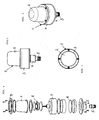
- FIG. 1 - 10 A first embodiment of an anti collision light for aircraft (hereinafter called ACL) is shown in Figures 1 - 10 .
- Figures 1 - 3 show the ACL from the outside in different views wherein it can be seen that the ACL 1 comprises a socket part 4, 5 a main housing 3 and a transparent cover 2. Within the transparent cover 2 the module 8 with the light emitting diodes is placed but is not shown in Figures 1 - 3 .
- the exploded view of Figure 4 shows the same elements and exposes the module 8 arranged on the housing part 3 and covered by the transparent cover 2.
- a ring shaped collar 9 mounts the cover 2 to the housing 3 and the module 8 is mounted to the same housing 3 as will be shown later in Figure 8 .
- housing 3 the electronic components for feeding the light emitting diodes with power (low voltage dc current) can be arranged on a circuit board 6.
- the housing 3 is closed by a lower part 4 which can belong to the socket or which can be part of the housing 3 itself.
- the socket 4 and 5 can be a screw type socket as shown or any other kind of socket for mounting the ACL to the aircraft as known to the man skilled in the art.
- FIGs 5, 6 and 7 show the module 8 in a preferred special embodiment.
- a plane 12 is shown on which the light emitting diodes are arranged as can be seen in Figure 8 .
- a reflecting means 16 in this case a parabolic reflector having a circular upper rim 16' reflects light that is emitted by light emitting diodes upwardly towards the reflecting means 16 in a sidewise manner as indicated by arrows A in Figure 5 since a number of light emitting diodes are arranged, preferably in a circle, around the lower rim 16'' of reflecting means 16.
- a spatial light emitting characteristic of the ACL of 360° can thus be achieved.
- the plane 12 and the reflecting means 16 are preferably arranged on a support 11.
- plane 22 On the same support 11 or on another support there may be another plane 22 which faces with its back the back of plane 12 and which carries a number of light emitting diodes as well.
- a reflecting means 26 is then arranged above plane 22.
- the light emitted by the light emitting diodes on plane 22 is emitted as well away from the plane mostly in a perpendicular direction to the plane and then falls on the reflecting means 26 and is directed sidewardly as is shown for example for a single light beam with arrows B in the same manner as for the other plane 12 with arrows A. So even if the reflecting means 26 is below plane 22 in the drawing it is here in view of the direction of the light said that reflecting means 26 is arranged above plane 22.
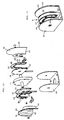
- FIG. 8 Exploded view of Figure 8 shows the construction of such an embodiment with two planes 12 and 22 but would be similar if only plane 12 and reflecting means 16 would be present.
- Plane 12 which is the basis for the light emitting diodes 13 is arranged on support 11 but could be of course held in other ways in ACL 1.
- Light emitting diodes 13 are arranged in a circle on plane 12 but of course could be arranged in other closed line forms for example in a rectangular form, open line forms, matrix arrangements or even in a random manner.
- Light emitting diodes 13 are preferably mounted directly on a plane 12 which is a circuit board that comprises the electric connections for the diodes 13.
- the diodes 13 are arranged as already mentioned in such a manner that their main direction of light emission is essentially perpendicular to plane 12.
- Diodes 13 may be arranged and mounted by automatic equipment for arranging electronic parts on printed circuit boards.
- Reflecting means 16 which are shown as the preferred parabolic circular rim reflector already mentioned is fixed to support 11 for example by two screws 66 shown above the reflecting means 16 and which fix as well the module 8 to the housing part 3.
- a printed circuit board 12' is fixed to support 11 by screws as well but could be fixed of course by any known means to the preferred support or by other known means to the housing of the ACL.
- the number of light emitting diodes is 20 but of course the number can be changed.
- the light emitting diodes are preferably connected electrically as shown in circuit diagram of Figure 10 and two electric connectors 30 are connecting all light emitting diodes to the electric feeding circuit which has been shown as a printed circuit board 6 in Figure 4 only but which could be of course arranged differently within the ACL.
- Each light emitting diode can be fed with a current of for example 0.5 to 0.8A and with a flash rate of for example 44 pulses per minute.
- the on-time can be for example 250 milliseconds a type of diode suited for such an ACL is for example the type MB042-SOL of red colour.
- FIG. 9 shows an example wherein the light emitting diode chip 13 is mounted directly on printed circuit board plane 12 in known manner and bond wires 13' are connected from chip 13 directly to board 12'. It is preferred that a transparent pourable plastic mass 52 for example a silicone mass is used to protect bond wires 13' and the light emitting diode chip 13.
- a frame 15 forms a compartment around each diode and contains the pourable mass 52 until this mass has sufficiently hardened.
- additional light reflecting means mounted on the plane 12 are arranged around each or some of the light emitting diodes 13. This can be achieved in an easy manner by having a ring around each or some of diodes 13 with light reflecting tapered sidewalls that reflect light emitted sidewardly by the diodes in a manner essentially perpendicular to plane 12.
- a number of such third reflecting means 15 are shown by holes with tapered walls in a ring shaped plate 14 that is fixed on plane 12 in such a manner that each diode has its own reflector 15.
- Reflector 15 can be at the same time frame 15 of Figure 9 for pouring in said transparent mass 52. In this way most of the light emitted by diodes 13 is emitted perpendicular to plane 12 either directly by the diode or by reflection on reflecting means 15.
- each diode chip can be for example a printed layer on said plane which is covered by a thin gold layer. Only the areas where the bond wires contact circuit board 12 and the printed connectors are leading from the bond wires to the contact areas of electric lines 30 on the printed circuit board (12') are of course not covered by reflector 17.
- another plane 22 can be arranged on support 11 or in another way within the housing of ACL 1 preferably in a back to back position to the first mentioned plane 12.
- this plane 22 and reflecting means 26 are mounted in a similar manner as first plane 12 and reflecting means 16. Screws 66 can be used to fix reflector 26 as well.
- Electric lines 31 are feeding light emitting diodes 23 on plane 22 which diodes are not visible in Figure 8 and are therefore only indicated by arrow 23.
- Additional fourth reflecting means 24 with holes 25 with tapered walls and arranged at the same positions as the light emitting diodes can be present (in the same manner as reflecting means 15) for the light emitting diodes 23 as well.
- the additional reflecting means 17 can be arranged as well on plane 22.
- Figures 11 and 12 show another embodiment similar to the one described before but which does not emit light around a full circle (360°). Accordingly, the support 11 which is preferably used here as well is approximately U-shaped around its rim. The same holds true for circuit boards 50 with their U-shaped rims 32 and 42 and for the arrangement of the light emitting diodes. Third and fourth reflecting means 54 and 64 with holes 55 are preferably present as well.
- the main reflecting means 36 and 46 with their rims 38 and 48 and the U-shaped rims 49 are preferably shaped in a parabolical way as well to direct light emitted by the diodes in a sidewards manner as explained before.
- the module 8 of this kind which is U-shaped or shaped like a horseshoe can be arranged in a bracket 60 as shown in Figures 11 and 12 .
- a housing which is not shown in the Figures and a clear cover which protects the module.
- the ACL according to the invention is not affected by vibrations as they occur on aircraft, has low weight and a very compact construction.
- the power consumption is low compared to conventional ACLs.
- the preferred embodiment with feeding circuit and led arrangement within the ACL itself is easy to mount to an airplane and enhances the above advantages.
- the ACL can be NVIS (Night Vision Systems) friendly without special filters due to the spectral characteristics of the LEDs used.
Landscapes
- Engineering & Computer Science (AREA)
- Aviation & Aerospace Engineering (AREA)
- Non-Portable Lighting Devices Or Systems Thereof (AREA)
- Aiming, Guidance, Guns With A Light Source, Armor, Camouflage, And Targets (AREA)
- Compositions Of Macromolecular Compounds (AREA)
- Polymers With Sulfur, Phosphorus Or Metals In The Main Chain (AREA)
- Traffic Control Systems (AREA)
- Road Signs Or Road Markings (AREA)
- Led Device Packages (AREA)
Claims (19)
- Antikollisionslicht (1) für ein Flugzeug umfassend eine Anzahl von ersten Leuchtdioden (13), die auf einer gemeinsamen Ebene (12) angeordnet sind, und ein Reflektionsmittel (16), das oberhalb der Ebene angeordnet ist, um von den Leuchtdioden im Wesentlichen senkrecht zu der genannten Ebene abgegebenes Licht in eine seitliche Richtung zu reflektieren, wobei das Reflektionsmittel (16) ein mehreren oder allen Leuchtdioden gemeinsamer Reflektor ist und wobei die Ebene (12) eine Platine ist, auf welcher Leuchtdioden-Chips direkt montiert sind, dadurch gekennzeichnet, dass einige oder jede der ersten Leuchtdioden (13) von einem zusätzlichen Reflektionsmittel (15) umgeben sind, welches zu der ersten Anzahl von Leuchtdioden (13) gehört, das von der Leuchtdiode oder den Leuchtdioden seitlich abgegebenes Licht in eine Richtung im Wesentlichen senkrecht zu der genannten Ebene (12) lenkt, wobei das genannte zusätzliche Reflektionsmittel (15) derart auf der Ebene montiert ist, dass jede erste Leuchtdiode (13) ihren eigenen Reflektor (15) hat, der dabei einen Rahmen zum Eingiessen einer transparenten Masse (52) bildet.
- Antikollisionslicht gemäss Anspruch 1, umfassend eine zweite Ebene (22), die einer zweiten Anzahl von Leuchtdioden (23), die auf dieser angeordnet sind, gemeinsam ist, wobei die erste und die zweite Ebene (12, 22) im Wesentlichen koplanar in einer Rücken-an-Rücken stehenden Weise angeordnet sind, und ein zweites Reflektionsmittel (26), das oberhalb der zweiten Ebene angeordnet ist, um von den Leuchtdioden der zweiten Anzahl von Leuchtdioden im Wesentlichen senkrecht zu der zweiten Ebene abgegebenes Licht in eine seitliche Richtung zu reflektieren, und insbesondere wobei das zweite Reflektionsmittel (26) ein Reflektor ist, der mehreren oder allen Leuchtdioden der genannten zweiten Anzahl von Leuchtdioden gemeinsam ist.
- Antikollisionslicht gemäss Anspruch 2, wobei die zweite Ebene (22) eine Platine ist, auf welcher Leuchtdiodenchips direkt montiert sind.
- Antikollisionslicht gemäss Anspruch 2, wobei einige oder jede der Leuchtdioden der zweiten Anzahl von Dioden (23), oder Gruppen von mehreren von den genannten Leuchtdioden zusammen, von einem zusätzlichen Reflektionsmittel (25) umgeben sind, welches zu der genannten zweiten Anzahl von Leuchtdioden (23) gehört und seitlich von der Leuchtdiode oder den Leuchtdioden abgegebenes Licht in eine Richtung im Wesentlichen senkrecht zu der genannten Ebene (22) lenkt.
- Antikollisionslicht gemäss Anspruch 4, wobei das genannte zusätzliche Reflektionsmittel (25) für die genannte zweite Anzahl von Leuchtdioden (23) auf der zweiten Ebene (22) montiert ist.
- Antikollisionslicht gemäss Anspruch 4 oder 5, wobei die genannten zusätzlichen Reflektionsmittel (15, 25) ringförmige Teile sind, die Löcher mit konischen, reflektierenden Seitenwänden haben, wobei die Löcher mit den Positionen der genannten Leuchtdioden korrespondierend auf der genannten Ebene bzw. den genannten Ebenen angeordnet sind.
- Antikollisionslicht gemäss einem der Ansprüche 1 bis 6, wobei die Leuchtdioden entlang einer geschlossenen Linie auf der Ebene bzw. den Ebenen angeordnet sind, insbesondere in einem Kreis, oder entlang einer offenen Linie auf der genannten Ebene bzw. den genannten Ebenen angeordnet sind, insbesondere in einer hufeisenähnlichen Form, oder in einer matrizenähnlichen Form angeordnet sind.
- Antikollisionslicht gemäss einem der Ansprüche 1 bis 7, wobei ein weiteres zusätzliches Reflektionsmittel (17) durch eine reflektierende Schicht auf der Ebene (12) bzw. den Ebenen (12, 22) für einige bzw. für jede der genannten Leuchtdioden bereitgestellt ist.
- Antikollisionslicht gemäss einem der Ansprüche 1 bis 8, wobei die genannten Reflektionsmittel (16, 26) oberhalb der genannten Ebene (12) oder der genannten Ebenen (12, 22) parabolisch geformt und mit einem kreisförmigen äusseren Rand (16') versehen sind.
- Antikollisionslicht gemäss Anspruch 9, wobei die genannte Ebene (12) oder die genannten Ebenen (12, 22) kreisförmige Platten bzw. Platinen sind.
- Antikollisionslicht gemäss einem der Ansprüche 1 bis 8, wobei die Reflektionsmittel (36, 46) oberhalb der genannten Ebene (32) oder der genannten Ebenen (32, 42) parabolisch geformt und mit zwei separaten Rändern (38, 48), die sich von der genannten Ebene (32) bzw. den genannten Ebenen (32, 42) erstrecken, und mit einem äusseren Rand (49), der U-förmig ist, versehen sind.
- Antikollisionslicht gemäss Anspruch 11, wobei die genannte Ebene (32) oder die genannten Ebenen (32, 42) Platten bzw. Platinen mit einem U-förmigen Rand (50) sind, der sich von einer linearen Basis (51) erstreckt.
- Antikollisionslicht gemäss einem der Ansprüche 1 bis 12, wobei die Leuchtdioden linsenlos sind.
- Antikollisionslicht gemäss einem der Ansprüche 1 bis 13, wobei die Leuchtdioden (13) von einer lichttransparenten Masse (52), insbesondere von einer giessbaren Silikonmasse, bedeckt sind.
- Antikollisionslicht gemäss Anspruch 14, wobei die genannten Reflektionsmittel (15, 25), die um die genannten Leuchtdioden herum angeordnet sind, und insbesondere das genannte dritte bzw. vierte Reflektionsmittel einen Rahmen für die genannte Masse bildet.
- Antikollisionslicht gemäss Anspruch 2, wobei eine Halterung (11) für die genannten Rücken-an-Rücken stehenden Ebenen vorgesehen ist, welche durch die genannte Halterung beabstandet sind.
- Antikollisionslicht gemäss einem der Ansprüche 2 bis 16, wobei die genannten Ebenen und die genannten Reflektionsmittel oberhalb der genannten Ebenen entlang einer gemeinsamen longitudinalen Achse angeordnet und insbesondere auf derselben Achse wie eine Fassung (4, 5) des Antikollisionslichts angeordnet sind.
- Antikollisionslicht gemäss einem der Ansprüche 2 bis 17, wobei die genannten Ebenen und die genannten Reflektionsmittel oberhalb der genannten Ebene entlang einer gemeinsamen Achse angeordnet und innerhalb eines U-förmigen Trägers (60) angeordnet sind.
- Antikollisionslicht gemäss einem der Ansprüche 1 bis 18, wobei die Leuchtdioden und eine Platine (6) für den elektrischen Versorgungskreis der Leuchtdioden innerhalb des Gehäuses des Antikollisionslichts (2, 3) angeordnet sind und insbesondere die Platine koplanar zu der Ebene (12) bzw. den Ebenen (12, 22) angeordnet ist.
Priority Applications (4)
| Application Number | Priority Date | Filing Date | Title |
|---|---|---|---|
| DE602004011708T DE602004011708T2 (de) | 2004-10-11 | 2004-10-11 | Antikollisionsleuchte für Luftfahrzeuge |
| EP04024156A EP1510457B1 (de) | 2004-10-11 | 2004-10-11 | Antikollisionsleuchte für Luftfahrzeuge |
| AT04024156T ATE385952T1 (de) | 2004-10-11 | 2004-10-11 | Antikollisionsleuchte für luftfahrzeuge |
| US11/033,275 US7236105B2 (en) | 2004-10-11 | 2005-01-12 | Anti collision light for aircraft |
Applications Claiming Priority (1)
| Application Number | Priority Date | Filing Date | Title |
|---|---|---|---|
| EP04024156A EP1510457B1 (de) | 2004-10-11 | 2004-10-11 | Antikollisionsleuchte für Luftfahrzeuge |
Publications (3)
| Publication Number | Publication Date |
|---|---|
| EP1510457A2 EP1510457A2 (de) | 2005-03-02 |
| EP1510457A3 EP1510457A3 (de) | 2005-04-06 |
| EP1510457B1 true EP1510457B1 (de) | 2008-02-13 |
Family
ID=34089806
Family Applications (1)
| Application Number | Title | Priority Date | Filing Date |
|---|---|---|---|
| EP04024156A Expired - Lifetime EP1510457B1 (de) | 2004-10-11 | 2004-10-11 | Antikollisionsleuchte für Luftfahrzeuge |
Country Status (4)
| Country | Link |
|---|---|
| US (1) | US7236105B2 (de) |
| EP (1) | EP1510457B1 (de) |
| AT (1) | ATE385952T1 (de) |
| DE (1) | DE602004011708T2 (de) |
Families Citing this family (28)
| Publication number | Priority date | Publication date | Assignee | Title |
|---|---|---|---|---|
| US7645053B2 (en) * | 2005-01-13 | 2010-01-12 | Honeywell International Inc. | Rotationally symmetrical LED-based anti-collision light for aircraft |
| FR2886713A1 (fr) * | 2005-06-06 | 2006-12-08 | Ece Soc Par Actions Simplifiee | Dispositif de signalisation lumineux anti-collision |
| ATE495102T1 (de) | 2007-06-13 | 2011-01-15 | Emteq Europ Gmbh | Antikollisionslicht für ein flugzeug |
| US20090010013A1 (en) * | 2007-07-02 | 2009-01-08 | Andre Hessling | Light for a vehicle, particularly flash warning light for an aircraft |
| US8665138B2 (en) * | 2007-07-17 | 2014-03-04 | Laufer Wind Group Llc | Method and system for reducing light pollution |
| ES2404661T3 (es) * | 2007-12-28 | 2013-05-28 | Sirio Panel S.P.A. | Luz anticolisión para avión |
| US20100027292A1 (en) * | 2008-07-29 | 2010-02-04 | Yun-Yuan Yeh | Light guiding structure |
| US20100027281A1 (en) * | 2008-07-31 | 2010-02-04 | Waters Stanley E | LED Anti-Collision Light for Commercial Aircraft |
| US8123377B2 (en) * | 2008-08-19 | 2012-02-28 | Honeywell International Inc. | Systems and methods for aircraft LED anti collision light |
| US20100090866A1 (en) * | 2008-10-13 | 2010-04-15 | Howard Chen | Optical Distress Beacon For Use In Space Environments |
| US7963683B2 (en) * | 2008-12-22 | 2011-06-21 | Federal Signal Corporation | Rotating light |
| US8192060B2 (en) * | 2009-07-23 | 2012-06-05 | Dean Andrew Wilkinson | Aircraft navigation light |
| US8662721B2 (en) * | 2009-11-26 | 2014-03-04 | Nathan Howard Calvin | Aircraft external lighting system and method |
| US9016896B1 (en) | 2011-02-23 | 2015-04-28 | Hughey & Phillips, Llc | Obstruction lighting system |
| US9013331B2 (en) | 2011-03-17 | 2015-04-21 | Hughey & Phillips, Llc | Lighting and collision alerting system |
| CA2771738C (en) | 2011-03-17 | 2018-05-15 | Hughey & Phillips, Llc | Lighting system |
| US8801241B2 (en) * | 2011-04-08 | 2014-08-12 | Dialight Corporation | High intensity warning light with reflector and light-emitting diodes |
| CN103216741B (zh) * | 2012-01-18 | 2016-12-14 | 欧司朗股份有限公司 | 照明装置、以及具有该照明装置的灯具 |
| EP2663162B1 (de) * | 2012-05-10 | 2017-01-11 | Goodrich Lighting Systems GmbH | LED-Blitzlicht und Verfahren zur Anzeige des nahen Endes der Lebensdauer eines derartigen LED-Blitzlichts |
| CN202972854U (zh) * | 2012-11-07 | 2013-06-05 | 北方海拉车灯有限公司 | 一种led车灯 |
| ITUD20130113A1 (it) * | 2013-09-02 | 2015-03-03 | Calzavara Spa | Dispositivo di segnalazione luminosa |
| CA2927419A1 (en) | 2015-04-16 | 2016-10-16 | Hughey & Phillips, Llc | Obstruction lighting system configured to emit visible and infrared light |
| CN104879709A (zh) * | 2015-05-05 | 2015-09-02 | 兰州万里航空机电有限责任公司 | 一种led高寿命飞机防撞灯 |
| US10004126B2 (en) * | 2015-06-22 | 2018-06-19 | Goodrich Lighting Systems, Inc. | Lighting-system color-shift detection and correction |
| US11178741B1 (en) | 2015-12-22 | 2021-11-16 | Hughey & Phillips, Llc | Lighting system configured to emit visible and infrared light |
| EP3670356B1 (de) | 2018-12-17 | 2023-08-30 | Goodrich Lighting Systems GmbH | Kombiniertes vorwärtsnavigations- und kollisionsschutzlicht für ein flugzeug und flugzeug damit |
| US11046455B2 (en) * | 2019-10-23 | 2021-06-29 | B/E Aerospace, Inc. | Anti-collision light assembly |
| EP4124794B1 (de) | 2021-07-28 | 2025-10-29 | Goodrich Lighting Systems GmbH & Co. KG | Äussere flugzeugbeleuchtung und flugzeug damit |
Citations (2)
| Publication number | Priority date | Publication date | Assignee | Title |
|---|---|---|---|---|
| US6367949B1 (en) * | 1999-08-04 | 2002-04-09 | 911 Emergency Products, Inc. | Par 36 LED utility lamp |
| US20040085779A1 (en) * | 2002-10-01 | 2004-05-06 | Pond Gregory R. | Light emitting diode headlamp and headlamp assembly |
Family Cites Families (24)
| Publication number | Priority date | Publication date | Assignee | Title |
|---|---|---|---|---|
| US2555807A (en) | 1946-08-08 | 1951-06-05 | Gyrodyne Company Of America In | Wing tip light for rotary wing aircraft |
| US3174552A (en) | 1963-12-09 | 1965-03-23 | Charles Adair | Rotary wing aircraft |
| JPS5565911A (en) | 1978-11-10 | 1980-05-17 | Canon Inc | Optical system of copying machine |
| US4527158A (en) * | 1982-07-29 | 1985-07-02 | Runnels Russell W | Aircraft collision pilot warning indicating system |
| ATE51331T1 (de) | 1985-07-04 | 1990-04-15 | Bbc Brown Boveri & Cie | Drehstromerreger fuer synchronmaschinen. |
| US4829407A (en) | 1987-11-06 | 1989-05-09 | Oxley Developments Company Limited | Indicator lamps |
| US4935665A (en) * | 1987-12-24 | 1990-06-19 | Mitsubishi Cable Industries Ltd. | Light emitting diode lamp |
| FR2690710B1 (fr) * | 1992-04-30 | 1994-06-17 | Snecma | Dispositif pour detecter une panne dans un echangeur huile/carburant. |
| JPH07201210A (ja) * | 1993-12-29 | 1995-08-04 | Patoraito:Kk | 信号表示灯の光源構造 |
| US5710560A (en) | 1994-04-25 | 1998-01-20 | The Regents Of The University Of California | Method and apparatus for enhancing visual perception of display lights, warning lights and the like, and of stimuli used in testing for ocular disease |
| US5499010A (en) | 1994-04-25 | 1996-03-12 | The Regents Of The University Of California | Braking light system for a vehicle |
| US5579162A (en) | 1994-10-31 | 1996-11-26 | Viratec Thin Films, Inc. | Antireflection coating for a temperature sensitive substrate |
| GB9603350D0 (en) | 1995-04-05 | 1996-04-17 | Oxley Dev Co Ltd | Aircraft lighting system |
| US5929788A (en) * | 1997-12-30 | 1999-07-27 | Star Headlight & Lantern Co. | Warning beacon |
| JP3906573B2 (ja) * | 1998-07-31 | 2007-04-18 | 東芝ライテック株式会社 | 標識灯 |
| US6278382B1 (en) | 1998-11-06 | 2001-08-21 | Demarco Ralph Anthony | Recognition/anti-collision light for aircraft |
| US6464373B1 (en) * | 2000-11-03 | 2002-10-15 | Twr Lighting, Inc. | Light emitting diode lighting with frustoconical reflector |
| US6483254B2 (en) * | 2000-12-20 | 2002-11-19 | Honeywell International Inc. | Led strobe light |
| EP1270409A1 (de) | 2001-06-15 | 2003-01-02 | Flight Components AG | Antikollisionsleuchte mit Infrarotfilter für Luftfahrzeuge |
| DE20114306U1 (de) * | 2001-08-31 | 2002-01-10 | aqua signal Aktiengesellschaft Spezialleuchtenfabrik, 28307 Bremen | Leuchtanlage insbesondere als Gefahrenfeuer, Hindernisfeuer oder Tag- und Nachtkennzeichen |
| US6525668B1 (en) * | 2001-10-10 | 2003-02-25 | Twr Lighting, Inc. | LED array warning light system |
| US6932496B2 (en) * | 2002-04-16 | 2005-08-23 | Farlight Llc | LED-based elevated omnidirectional airfield light |
| DE20311169U1 (de) * | 2003-07-21 | 2003-10-09 | Hella KG Hueck & Co., 59557 Lippstadt | Signalleuchte |
| US7079041B2 (en) * | 2003-11-21 | 2006-07-18 | Whelen Engineering Company, Inc. | LED aircraft anticollision beacon |
-
2004
- 2004-10-11 AT AT04024156T patent/ATE385952T1/de not_active IP Right Cessation
- 2004-10-11 EP EP04024156A patent/EP1510457B1/de not_active Expired - Lifetime
- 2004-10-11 DE DE602004011708T patent/DE602004011708T2/de not_active Expired - Lifetime
-
2005
- 2005-01-12 US US11/033,275 patent/US7236105B2/en not_active Expired - Fee Related
Patent Citations (2)
| Publication number | Priority date | Publication date | Assignee | Title |
|---|---|---|---|---|
| US6367949B1 (en) * | 1999-08-04 | 2002-04-09 | 911 Emergency Products, Inc. | Par 36 LED utility lamp |
| US20040085779A1 (en) * | 2002-10-01 | 2004-05-06 | Pond Gregory R. | Light emitting diode headlamp and headlamp assembly |
Also Published As
| Publication number | Publication date |
|---|---|
| EP1510457A2 (de) | 2005-03-02 |
| DE602004011708D1 (de) | 2008-03-27 |
| US7236105B2 (en) | 2007-06-26 |
| ATE385952T1 (de) | 2008-03-15 |
| EP1510457A3 (de) | 2005-04-06 |
| DE602004011708T2 (de) | 2009-01-29 |
| US20060077071A1 (en) | 2006-04-13 |
Similar Documents
| Publication | Publication Date | Title |
|---|---|---|
| EP1510457B1 (de) | Antikollisionsleuchte für Luftfahrzeuge | |
| US7434970B2 (en) | Multi-platform LED-based aircraft rear position light | |
| EP2003058B1 (de) | Antikollisionslicht für ein Flugzeug | |
| JP5779329B2 (ja) | 車両用灯具 | |
| EP1168902B1 (de) | Festkörper Lichtquelle Anordnung | |
| US7314296B2 (en) | Multi-platform aircraft forward position light utilizing LED-based light source | |
| US7431486B2 (en) | LED assembly for rear lamps in an automobile | |
| US6461029B2 (en) | Led position lamp | |
| EP2586709B1 (de) | Modulares LED-basiertes hinteres Flugzeugpositionslicht | |
| US10054283B2 (en) | Compact multi-function LED lighthead | |
| JP2011171277A (ja) | 車両用灯具の半導体型光源の光源ユニット、車両用灯具 | |
| EP2392511B1 (de) | Flugzeugpositionslichtanordnung | |
| CN103347738A (zh) | 用于机动车中的内部照明的设备 | |
| WO2019035011A1 (en) | AERODROME MARKING FIRE | |
| US20020145533A1 (en) | High intensity flashing light | |
| US20050225452A1 (en) | Indicator apparatus and method for a vehicle using side-emitting light-emitting diode | |
| JP5407026B2 (ja) | 車両用灯具の半導体型光源の光源ユニット、車両用灯具 | |
| US20230265996A1 (en) | Aircraft light and aircraft comprising the same | |
| US20060028815A1 (en) | Light assembly comprising integrated passive and active illumination sources | |
| US20240044472A1 (en) | Light source for the signalling system of a motor vehicle | |
| EP2581644A1 (de) | LED-Anflugfeuer | |
| CN100436259C (zh) | 利用基于led的光源的多平台飞机前部位置指示灯 | |
| MXPA01002133A (es) | Estructura de marcador de cabina con diodos emisores de luz, aerodinamica. |
Legal Events
| Date | Code | Title | Description |
|---|---|---|---|
| PUAI | Public reference made under article 153(3) epc to a published international application that has entered the european phase |
Free format text: ORIGINAL CODE: 0009012 |
|
| PUAL | Search report despatched |
Free format text: ORIGINAL CODE: 0009013 |
|
| AK | Designated contracting states |
Kind code of ref document: A2 Designated state(s): AT BE BG CH CY CZ DE DK EE ES FI FR GB GR HU IE IT LI LU MC NL PL PT RO SE SI SK TR |
|
| AX | Request for extension of the european patent |
Extension state: AL HR LT LV MK |
|
| AK | Designated contracting states |
Kind code of ref document: A3 Designated state(s): AT BE BG CH CY CZ DE DK EE ES FI FR GB GR HU IE IT LI LU MC NL PL PT RO SE SI SK TR |
|
| AX | Request for extension of the european patent |
Extension state: AL HR LT LV MK |
|
| 17P | Request for examination filed |
Effective date: 20051004 |
|
| AKX | Designation fees paid |
Designated state(s): AT BE BG CH CY CZ DE DK EE ES FI FR GB GR HU IE IT LI LU MC NL PL PT RO SE SI SK TR |
|
| 17Q | First examination report despatched |
Effective date: 20051125 |
|
| GRAP | Despatch of communication of intention to grant a patent |
Free format text: ORIGINAL CODE: EPIDOSNIGR1 |
|
| GRAS | Grant fee paid |
Free format text: ORIGINAL CODE: EPIDOSNIGR3 |
|
| GRAA | (expected) grant |
Free format text: ORIGINAL CODE: 0009210 |
|
| AK | Designated contracting states |
Kind code of ref document: B1 Designated state(s): AT BE BG CH CY CZ DE DK EE ES FI FR GB GR HU IE IT LI LU MC NL PL PT RO SE SI SK TR |
|
| REG | Reference to a national code |
Ref country code: GB Ref legal event code: FG4D |
|
| REG | Reference to a national code |
Ref country code: CH Ref legal event code: NV Representative=s name: E. BLUM & CO. AG PATENT- UND MARKENANWAELTE VSP Ref country code: CH Ref legal event code: EP |
|
| REG | Reference to a national code |
Ref country code: IE Ref legal event code: FG4D |
|
| REF | Corresponds to: |
Ref document number: 602004011708 Country of ref document: DE Date of ref document: 20080327 Kind code of ref document: P |
|
| PG25 | Lapsed in a contracting state [announced via postgrant information from national office to epo] |
Ref country code: FI Free format text: LAPSE BECAUSE OF FAILURE TO SUBMIT A TRANSLATION OF THE DESCRIPTION OR TO PAY THE FEE WITHIN THE PRESCRIBED TIME-LIMIT Effective date: 20080213 Ref country code: ES Free format text: LAPSE BECAUSE OF FAILURE TO SUBMIT A TRANSLATION OF THE DESCRIPTION OR TO PAY THE FEE WITHIN THE PRESCRIBED TIME-LIMIT Effective date: 20080524 |
|
| NLV1 | Nl: lapsed or annulled due to failure to fulfill the requirements of art. 29p and 29m of the patents act | ||
| PG25 | Lapsed in a contracting state [announced via postgrant information from national office to epo] |
Ref country code: AT Free format text: LAPSE BECAUSE OF FAILURE TO SUBMIT A TRANSLATION OF THE DESCRIPTION OR TO PAY THE FEE WITHIN THE PRESCRIBED TIME-LIMIT Effective date: 20080213 |
|
| ET | Fr: translation filed | ||
| PG25 | Lapsed in a contracting state [announced via postgrant information from national office to epo] |
Ref country code: BE Free format text: LAPSE BECAUSE OF FAILURE TO SUBMIT A TRANSLATION OF THE DESCRIPTION OR TO PAY THE FEE WITHIN THE PRESCRIBED TIME-LIMIT Effective date: 20080213 Ref country code: PL Free format text: LAPSE BECAUSE OF FAILURE TO SUBMIT A TRANSLATION OF THE DESCRIPTION OR TO PAY THE FEE WITHIN THE PRESCRIBED TIME-LIMIT Effective date: 20080213 Ref country code: SI Free format text: LAPSE BECAUSE OF FAILURE TO SUBMIT A TRANSLATION OF THE DESCRIPTION OR TO PAY THE FEE WITHIN THE PRESCRIBED TIME-LIMIT Effective date: 20080213 |
|
| PG25 | Lapsed in a contracting state [announced via postgrant information from national office to epo] |
Ref country code: DK Free format text: LAPSE BECAUSE OF FAILURE TO SUBMIT A TRANSLATION OF THE DESCRIPTION OR TO PAY THE FEE WITHIN THE PRESCRIBED TIME-LIMIT Effective date: 20080213 Ref country code: NL Free format text: LAPSE BECAUSE OF FAILURE TO SUBMIT A TRANSLATION OF THE DESCRIPTION OR TO PAY THE FEE WITHIN THE PRESCRIBED TIME-LIMIT Effective date: 20080213 Ref country code: PT Free format text: LAPSE BECAUSE OF FAILURE TO SUBMIT A TRANSLATION OF THE DESCRIPTION OR TO PAY THE FEE WITHIN THE PRESCRIBED TIME-LIMIT Effective date: 20080714 Ref country code: SE Free format text: LAPSE BECAUSE OF FAILURE TO SUBMIT A TRANSLATION OF THE DESCRIPTION OR TO PAY THE FEE WITHIN THE PRESCRIBED TIME-LIMIT Effective date: 20080513 Ref country code: CZ Free format text: LAPSE BECAUSE OF FAILURE TO SUBMIT A TRANSLATION OF THE DESCRIPTION OR TO PAY THE FEE WITHIN THE PRESCRIBED TIME-LIMIT Effective date: 20080213 Ref country code: SK Free format text: LAPSE BECAUSE OF FAILURE TO SUBMIT A TRANSLATION OF THE DESCRIPTION OR TO PAY THE FEE WITHIN THE PRESCRIBED TIME-LIMIT Effective date: 20080213 |
|
| PG25 | Lapsed in a contracting state [announced via postgrant information from national office to epo] |
Ref country code: RO Free format text: LAPSE BECAUSE OF FAILURE TO SUBMIT A TRANSLATION OF THE DESCRIPTION OR TO PAY THE FEE WITHIN THE PRESCRIBED TIME-LIMIT Effective date: 20080213 |
|
| PLBE | No opposition filed within time limit |
Free format text: ORIGINAL CODE: 0009261 |
|
| STAA | Information on the status of an ep patent application or granted ep patent |
Free format text: STATUS: NO OPPOSITION FILED WITHIN TIME LIMIT |
|
| 26N | No opposition filed |
Effective date: 20081114 |
|
| PG25 | Lapsed in a contracting state [announced via postgrant information from national office to epo] |
Ref country code: BG Free format text: LAPSE BECAUSE OF FAILURE TO SUBMIT A TRANSLATION OF THE DESCRIPTION OR TO PAY THE FEE WITHIN THE PRESCRIBED TIME-LIMIT Effective date: 20080513 Ref country code: EE Free format text: LAPSE BECAUSE OF FAILURE TO SUBMIT A TRANSLATION OF THE DESCRIPTION OR TO PAY THE FEE WITHIN THE PRESCRIBED TIME-LIMIT Effective date: 20080213 |
|
| PG25 | Lapsed in a contracting state [announced via postgrant information from national office to epo] |
Ref country code: MC Free format text: LAPSE BECAUSE OF NON-PAYMENT OF DUE FEES Effective date: 20081031 |
|
| PG25 | Lapsed in a contracting state [announced via postgrant information from national office to epo] |
Ref country code: CY Free format text: LAPSE BECAUSE OF FAILURE TO SUBMIT A TRANSLATION OF THE DESCRIPTION OR TO PAY THE FEE WITHIN THE PRESCRIBED TIME-LIMIT Effective date: 20080213 |
|
| PG25 | Lapsed in a contracting state [announced via postgrant information from national office to epo] |
Ref country code: IE Free format text: LAPSE BECAUSE OF NON-PAYMENT OF DUE FEES Effective date: 20081013 |
|
| PG25 | Lapsed in a contracting state [announced via postgrant information from national office to epo] |
Ref country code: HU Free format text: LAPSE BECAUSE OF FAILURE TO SUBMIT A TRANSLATION OF THE DESCRIPTION OR TO PAY THE FEE WITHIN THE PRESCRIBED TIME-LIMIT Effective date: 20080814 Ref country code: LU Free format text: LAPSE BECAUSE OF NON-PAYMENT OF DUE FEES Effective date: 20081011 |
|
| PG25 | Lapsed in a contracting state [announced via postgrant information from national office to epo] |
Ref country code: TR Free format text: LAPSE BECAUSE OF FAILURE TO SUBMIT A TRANSLATION OF THE DESCRIPTION OR TO PAY THE FEE WITHIN THE PRESCRIBED TIME-LIMIT Effective date: 20080213 |
|
| REG | Reference to a national code |
Ref country code: CH Ref legal event code: PFA Owner name: EMTEQ EUROPE GMBH Free format text: FLIGHT COMPONENTS AG#BITZIBERGSTRASSE 5#8184 BACHENBUELACH (CH) -TRANSFER TO- EMTEQ EUROPE GMBH#BITZIBERGSTRASSE 5#8184 BACHENBUELACH (CH) |
|
| PG25 | Lapsed in a contracting state [announced via postgrant information from national office to epo] |
Ref country code: GR Free format text: LAPSE BECAUSE OF FAILURE TO SUBMIT A TRANSLATION OF THE DESCRIPTION OR TO PAY THE FEE WITHIN THE PRESCRIBED TIME-LIMIT Effective date: 20080514 |
|
| REG | Reference to a national code |
Ref country code: FR Ref legal event code: CD |
|
| PGFP | Annual fee paid to national office [announced via postgrant information from national office to epo] |
Ref country code: CH Payment date: 20130906 Year of fee payment: 10 |
|
| PGFP | Annual fee paid to national office [announced via postgrant information from national office to epo] |
Ref country code: FR Payment date: 20131022 Year of fee payment: 10 Ref country code: DE Payment date: 20131021 Year of fee payment: 10 Ref country code: GB Payment date: 20131021 Year of fee payment: 10 |
|
| PGFP | Annual fee paid to national office [announced via postgrant information from national office to epo] |
Ref country code: IT Payment date: 20131024 Year of fee payment: 10 |
|
| REG | Reference to a national code |
Ref country code: DE Ref legal event code: R119 Ref document number: 602004011708 Country of ref document: DE |
|
| REG | Reference to a national code |
Ref country code: CH Ref legal event code: PL |
|
| GBPC | Gb: european patent ceased through non-payment of renewal fee |
Effective date: 20141011 |
|
| PG25 | Lapsed in a contracting state [announced via postgrant information from national office to epo] |
Ref country code: GB Free format text: LAPSE BECAUSE OF NON-PAYMENT OF DUE FEES Effective date: 20141011 Ref country code: LI Free format text: LAPSE BECAUSE OF NON-PAYMENT OF DUE FEES Effective date: 20141031 Ref country code: CH Free format text: LAPSE BECAUSE OF NON-PAYMENT OF DUE FEES Effective date: 20141031 Ref country code: DE Free format text: LAPSE BECAUSE OF NON-PAYMENT OF DUE FEES Effective date: 20150501 |
|
| REG | Reference to a national code |
Ref country code: FR Ref legal event code: ST Effective date: 20150630 |
|
| PG25 | Lapsed in a contracting state [announced via postgrant information from national office to epo] |
Ref country code: FR Free format text: LAPSE BECAUSE OF NON-PAYMENT OF DUE FEES Effective date: 20141031 Ref country code: IT Free format text: LAPSE BECAUSE OF NON-PAYMENT OF DUE FEES Effective date: 20141011 |