EP1510421A2 - Vehicular hood structure - Google Patents
Vehicular hood structure Download PDFInfo
- Publication number
- EP1510421A2 EP1510421A2 EP04020445A EP04020445A EP1510421A2 EP 1510421 A2 EP1510421 A2 EP 1510421A2 EP 04020445 A EP04020445 A EP 04020445A EP 04020445 A EP04020445 A EP 04020445A EP 1510421 A2 EP1510421 A2 EP 1510421A2
- Authority
- EP
- European Patent Office
- Prior art keywords
- hood
- inner panel
- vehicle body
- vehicular
- hood inner
- Prior art date
- Legal status (The legal status is an assumption and is not a legal conclusion. Google has not performed a legal analysis and makes no representation as to the accuracy of the status listed.)
- Granted
Links
- 230000002787 reinforcement Effects 0.000 claims abstract description 45
- 239000011324 bead Substances 0.000 abstract description 5
- VRDIULHPQTYCLN-UHFFFAOYSA-N Prothionamide Chemical compound CCCC1=CC(C(N)=S)=CC=N1 VRDIULHPQTYCLN-UHFFFAOYSA-N 0.000 abstract 1
- 230000035939 shock Effects 0.000 description 14
- 230000000694 effects Effects 0.000 description 4
- 230000001133 acceleration Effects 0.000 description 3
- 230000000052 comparative effect Effects 0.000 description 3
- 238000003466 welding Methods 0.000 description 3
- 239000000853 adhesive Substances 0.000 description 2
- 230000001070 adhesive effect Effects 0.000 description 2
- 238000000926 separation method Methods 0.000 description 2
- 230000002452 interceptive effect Effects 0.000 description 1
Images


Classifications
-
- B—PERFORMING OPERATIONS; TRANSPORTING
- B62—LAND VEHICLES FOR TRAVELLING OTHERWISE THAN ON RAILS
- B62D—MOTOR VEHICLES; TRAILERS
- B62D25/00—Superstructure or monocoque structure sub-units; Parts or details thereof not otherwise provided for
- B62D25/08—Front or rear portions
- B62D25/10—Bonnets or lids, e.g. for trucks, tractors, busses, work vehicles
- B62D25/105—Bonnets or lids, e.g. for trucks, tractors, busses, work vehicles for motor cars
-
- B—PERFORMING OPERATIONS; TRANSPORTING
- B60—VEHICLES IN GENERAL
- B60R—VEHICLES, VEHICLE FITTINGS, OR VEHICLE PARTS, NOT OTHERWISE PROVIDED FOR
- B60R21/00—Arrangements or fittings on vehicles for protecting or preventing injuries to occupants or pedestrians in case of accidents or other traffic risks
- B60R21/34—Protecting non-occupants of a vehicle, e.g. pedestrians
- B60R2021/343—Protecting non-occupants of a vehicle, e.g. pedestrians using deformable body panel, bodywork or components
Definitions
- the present invention relates to a vehicular hood (bonnet) structure, and in particular to a vehicular hood structure applied to a vehicle such as an automobile.
- a configuration is known where a reinforcement panel folded in a trapezoidal shape by a front slanted panel, a top panel and a rear slanted panel is attached to the site of a hood inner panel disposed with a lock reinforcement, the top panel is divided into a front top panel and a rear top panel by a slit, and edge reinforcement members that reinforce the edges of the front top panel and the rear top panel are attached to the front top panel and the rear top panel, whereby hood rigidity is secured and the shock of a collision body is alleviated (e.g., see Japanese Patent Application Laid-Open Publication (JP-A) No. 11-321714).
- JP-A Japanese Patent Application Laid-Open Publication
- a configuration is also known where a reinforcement panel is adhered to the site of an undersurface side of a hood outer panel above the lock reinforcement, whereby safety at the time of a collision is improved (e.g., see JP-A No. 2002-37129.
- a vehicular hood structure is demanded with which hood rigidity can be secured and which can alleviate the shock of a collision body without increasing the number of parts.
- a vehicular hood structure of the invention includes: a lock reinforcement that is disposed at a lower surface side of a hood inner panel at a predetermined interval away from the hood inner panel and which forms a closed cross-sectional structure with the hood inner panel; and a rear-side attachment portion that is formed in the hood inner panel and to which is fixed a vehicle body rear-side attachment portion of the lock reinforcement.
- the rear-side attachment portion of the hood inner panel forms a swollen portion that swells further downward with respect to the vehicle body than other sites of the hood inner panel.
- the lock reinforcement is largely separated from the hood inner panel.
- the rigidity of the hood can be secured by the closed cross-sectional structure formed by the hood inner panel and the lock reinforcement.
- the rear-side attachment portion of the hood inner panel to which is fixed the vehicle body rear-side attachment portion of the lock reinforcement serves as the swollen portion that swells further downward with respect to the vehicle body than other sites of the hood inner panel, and the lock reinforcement is largely separated from the hood inner panel.
- the vehicular hood structure of the invention may further include a cut-and-raised portion that is formed in part of the rear-side attachment portion of the hood inner panel and is joined to a hood outer panel.
- the number of joints between the hood inner panel and the hood outer panel is increased by the cut-and-raised portion that is formed in part of the rear-side attachment portion of the hood inner panel and is joined to the hood outer panel.
- the torsional rigidity of the hood can also be improved.
- a stepped portion may be formed in the rear-side attachment portion of the hood inner panel.
- the stepped portion formed in the rear-side attachment portion of the hood inner panel Due to the stepped portion formed in the rear-side attachment portion of the hood inner panel, the stepped portion is locally deformed when a collision body collides with the hood at a site further rearward than the rear-side attachment portion of the hood inner panel. As a result, the performance with respect to alleviating the shock of the collision body is further improved because the influence of the lock reinforcement can be alleviated when the site of the hood at which the collision body has collided is deformed.
- a distance in a front-rear direction between the rear-side attachment portion of the hood inner panel and a hood lock striker may be set to be at least twice a distance in a vertical direction between the hood inner panel and the hood lock striker.
- the distance in the front-rear direction between the rear-side attachment portion of the hood inner panel and the hood lock striker is set to be at least twice the distance in the vertical direction between the hood inner panel and the hood lock striker, the site at which the collision body has collided easily rotates downward starting at the rear-side attachment portion when a collision body strikes the hood from above the hood lock striker.
- the performance with respect to alleviating the shock of the collision body is further improved.
- the rear-side attachment portion of the hood inner panel serves as the swollen portion that swells further downward with respect to the vehicle body than other sites of the hood inner panel, and the lock reinforcement is largely separated from the hood inner panel.
- the rigidity of the hood can be secured and the shock of a collision body can be alleviated without increasing the number of parts.
- the torsional rigidity of the hood is improved even if the vehicular hood structure includes a cut-and-raised portion that is formed in part of the rear-side attachment portion of the hood inner panel and is joined to the hood outer panel.
- the shock alleviating performance is further improved even if a stepped portion is formed in the rear-side attachment portion in the vehicular hood structure.
- the shock alleviating performance is further improved even if the distance in the front-rear direction between the rear-side attachment portion of the hood inner panel and the hood lock striker is set to be at least twice the distance in the vertical direction between the hood inner panel and the hood lock striker.
- a first embodiment of a vehicular hood structure of the invention will be described in accordance with Figs. 1 to 3.
- the UP arrow represents a vehicle body up direction
- the FR arrow represents a vehicle body front direction
- a known hood lock mechanism 14 is disposed at a vehicle width-direction center portion 12A of a front end edge portion of a hood 12 of an automobile body 10.
- the hood (bonnet) 12 is configured by a hood outer panel 16, which configures a vehicle body outer side surface of the hood 12, and a hood inner panel 18, which is disposed at the inner side (undersurface side) of the hood outer panel 16.
- a swollen portion 18B (rear-side attachment portion of a lock reinforcement) that swells downward with respect to the vehicle body is formed at a position in the hood inner panel 18 separated by a predetermined distance from a front end portion 18A towards the vehicle body rear.
- the swollen portion 18B is formed along the vehicle width direction.
- the swollen portion 18B has a substantial "U" shape that opens upward with respect to the vehicle body when seen from the side, and includes a front slanted portion 18D, a bottom portion 18C and a rear slanted portion 18E.
- a striker body 20 (hood lock striker) of the hood lock mechanism 14 is fixed, via a base plate 22, to a lower wall portion 24A of a lock reinforcement 24. Also, a front end edge portion 24B of the lock reinforcement 24 is joined to a front end edge portion 16A of the hood outer panel 16, and a slanted wall 24C that extends upward and rearward with respect to the vehicle body is formed at a rear side of the lower wall portion 24A of the lock reinforcement 24.
- a flange 24D is formed facing the vehicle body rear at a rear end edge portion of the slanted wall 24C, and the flange 24D is joined to a lower surface of the bottom portion 18C of the swollen portion 18B of the hood inner panel 18.
- the hood inner panel 18 blocks off the open portion of the lock reinforcement 24, so that a front side bead 28 (closed cross-sectional structure) serving as a closed cross-sectional structure extending in the vehicle width direction is formed by the lock reinforcement 24 and the hood inner panel 18.
- the swollen portion 18B of the hood inner panel 18 serves as the rear-side attachment portion of the lock reinforcement 24, and the flange 24D of the lock reinforcement 24 is largely separated from the hood outer panel 16 in the vehicle body vertical direction (separation distance H3).
- a cut-and-raised portion 30 having a predetermined width in the vehicle width direction is formed at a predetermined interval in the vehicle width direction at the front slanted portion 18D of the swollen portion B serving as the rear-side attachment portion of the lock reinforcement 24, and a top portion 30A of the cut-and-raised portion 30 is adhered with an adhesive 32 to the hood outer panel 16.
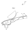
- the rigidity of the hood 12 can be secured by the front side bead 28 formed at the front end portion of the hood 12 by the hood inner panel 18 and the lock reinforcement 24. For this reason, it is not necessary to separately use, as in the comparative example shown in Fig. 4, a reinforcement panel 104 to block off an opening at the upper portion of a lock reinforcement 102 disposed at the front end portion of a hood 12.
- the rear-side attachment portion of the hood inner panel 18 to which is joined the flange 24D serves as the swollen portion 18B that swells downward with respect to the vehicle body.
- the flange 24D, which has another part of the attachment portion to the vehicle body, of the lock reinforcement 24 is largely separated from the hood outer panel 16 in the vehicle body vertical direction (separation distance H3).
- the change in an acceleration G 1 with respect to a form stroke of the collision body S in the present embodiment becomes more gradual at the start of the early stage of the collision in comparison to the change in an acceleration G2 with respect to the stroke of the collision body S in the comparative example of Fig. 4, so that the shock of the collision body S can be alleviated.
- hood rigidity can be secured and the shock of a collision body can be alleviated without increasing the number of parts.
- the cut-and-raised portion 30 having a predetermined width in the vehicle width direction is formed at the front slanted portion 18D of the swollen portion 18B serving as the rear-side attachment portion of the lock reinforcement 24, and the top portion 30A of the cut-and-raised portion 30 is fixed with the adhesive 32 to the hood outer panel 16. For this reason, the number of joints between the hood inner panel 18 and the hood outer panel 16 is increased and the torsional rigidity of the hood 12 can be improved.
- the invention may also be configured so that the deformation load of the front slanted portion 18D is controlled by forming a hole, slit, bead or step in the front slanted portion 18D of the hood inner panel 18 above the lock reinforcement 24.
- a separate panel with a thinner panel thickness than that of the site at the rear side may be used at the site in front of the bottom portion 18C of the swollen portion 18 of the hood inner panel 18, and both may be joined.
- the panel thickness of the site in front of the bottom panel 18C of the swollen portion 18B of the hood inner panel 18 may be made thinner in comparison to the site at the rear side by a tailored blank.
- a distance L in the front-rear direction between a front-rear direction center portion of the striker body 20 of the hood lock mechanism 14 and a welding point P between the swollen portion 18B and the flange 24D is set to be at least 150 mm (L ⁇ 150 mm), and the distance L is at least twice a maximum distance H2 in the vertical direction between the hood inner panel 18 and the striker body 20 (L ⁇ 2H2).
- the distance L in the front-rear direction between the front-rear direction center portion of the striker body 20 of the hood lock mechanism 14 and the welding point P between the swollen portion 18B and the flange 24D is set to be at least 150 mm (L ⁇ 150 mm), and the distance L is at least twice the maximum distance H2 in the vertical direction between the hood inner panel 18 and the striker body 20 (L ⁇ 2H2).
- a stepped portion 50 that curves upward with respect to the vehicle body is formed along the vehicle width direction in the rear slanted portion 18E of the swollen portion 18B formed in the hood inner panel 18.
- the stepped portion 50 which is between the common portion 18F and the site above the lock reinforcement 24, is locally deformed.
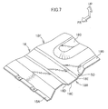
- the hood inner panel 18 of the present embodiment is a so-called double structure type, and a convex portion 18G that swells upward with respect to the vehicle body is formed along the vehicle body front-rear direction in the common portion 18F of the hood inner panel 18.
- the stepped portion 50 that curves upward with respect to the vehicle body is formed along the vehicle width direction in the rear slanted portion 18E of the swollen portion 18B formed in the hood inner panel 18.
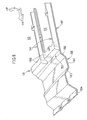
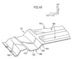
- the hood inner panel 18 of the present embodiment was a so-called double structure type, but as shown in Fig. 8, plural cutouts 52 may be formed in the hood inner panel 18 in the vehicle body front-rear direction, so that a so-called beam type is formed where beams 54 are formed between adjacent cutouts 52.
- a convex portion 18H that is upwardly convex with respect to the vehicle body near the hood outer panel 18 is formed along the vehicle width direction adjacent to the rear side of the swollen portion 18B formed in the hood inner panel 18, and a thickness T1 of the hood 12 at the top portion of this convex portion 18H is thinner than a panel thickness T2 of other sites.
- the hood inner panel 18 of the present embodiment is a so-called double structure type, and concave portions 18K that are downwardly concave with respect to the vehicle body are formed along the vehicle body front-rear direction in the common portion 18J of the hood inner panel 18.
- the convex portion 18H that is upwardly convex with respect to the vehicle body near the hood outer panel 18 is formed along the vehicle width direction adjacent to the rear side of the swollen portion 18B formed in the hood inner panel 18.
- the hood inner panel 18 of the present embodiment was a so-called double structure type, but as shown in Fig. 11, plural cutouts 52 may be formed in the hood inner panel 18 in the vehicle body front-rear direction, so that a so-called beam type is formed where beams 54 are formed between adjacent cutouts 52.
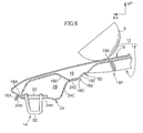
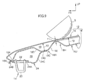
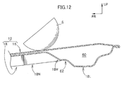
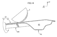
- a swollen portion 18L that swells downward with respect to the vehicle body is formed in the rear end portion of the hood inner panel 18 of the hood 12, and a rear side beam 60 that extends in the vehicle width direction is formed by the swollen portion 18L and the rear end portion of the hood outer panel 16.
- the rear side beam 60 is disposed at the rear end edge portion of the hood 12 for a cowl seal.
- a stepped portion 62 that curves upward with respect to the vehicle body is formed along the vehicle width direction in a front slanted portion 18M of the swollen portion 18L formed in the hood inner panel 18.
- the stepped portion 62 which is between the common portion 18N and the rear side beam 60, is locally deformed.
- the stepped portion 62 that curves upward with respect to the vehicle body is formed along the vehicle width direction in the front slanted portion 18M of the swollen portion 18L formed in the hood inner panel 18.
- the rigidity of the hood 12 can be secured without increasing the number of parts, and the shock of the collision body S can be alleviated when a collision body S with a light mass collides near the rear end portion of the hood 12 in a case where the vehicle body is small and the position of the hood 12 is low or in a case where the front-rear length of the hood 12 is short.
- a convex portion 18P that is upwardly convex with respect to the vehicle body near the hood outer panel 16 is formed adjacent to the front side of the swollen portion 18L formed in the hood inner panel 18, and a thickness T3 of the hood 12 at this convex portion 18P is thinner than a thickness T4 of the hood 2 at the common portion 18N and a thickness T5 of the hood 12 at the rear side beam 60.
- the convex portion 18P which is between the common portion 18N and the rear side beam 60, is locally deformed.
- the convex portion 18P that is upwardly convex with respect to the vehicle body near the hood outer panel 16 is formed adjacent to the front side of the swollen portion 18L formed in the hood inner panel 18.
- the rigidity of the hood 12 can be secured without increasing the number of parts, and the shock of the collision body S can be alleviated when a collision body S with a light mass collides near the rear end portion of the hood 12 in a case where the vehicle body is small and the position of the hood 12 is low or in a case where the front-rear length of the hood 12 is short.
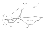
- the invention may be configured so that, as shown in Fig. 14, a stepped portion or a projecting portion is not formed along the rear side beam 60 of the hood inner panel 18.
- a primary collision when a collision body contacts the hood 12
- the amount of absorbed energy at the time of a primary collision can be sufficiently secured when a collision body S with a large mass collides with the hood 12 near the rear side beam 60.
- a secondary collision when the hood 12 collides with a part inside the hood or the vehicle body of the collision body can be alleviated.
- the wrap-around distance (WAD) of the hood 12 is 1500 m to 1700 mm, and a collision body with a light mass easily collides with a site in front of that, and a collision body with a heavy mass easily collides with a site behind that.
- the stepped portion 62 described in the fifth embodiment is formed in side beams formed along the vehicle body front-rear direction at both vehicle width-direction end portions of the hood 12, and at the site at the rear side where the WAD is larger than 1700 mm, the stepped portion 62 shown in Fig. 12 is not formed in the side beams.
- the shape of the stepped portion may be gradually changed with respect to the site where the WAD of the hood 12 is 1500 to 1700 mm. As a result, error can be effectively reduced in correspondence to differences in the mass of collision bodies even at both vehicle width-direction end portions of the hood 12.
Landscapes
- Engineering & Computer Science (AREA)
- Mechanical Engineering (AREA)
- Chemical & Material Sciences (AREA)
- Combustion & Propulsion (AREA)
- Transportation (AREA)
- Superstructure Of Vehicle (AREA)
Abstract
Description
Claims (10)
- A vehicular hood structure including:wherein the rear-side attachment portion formed in the hood inner panel forms a swollen portion that swells further downward with respect to the vehicle body than other sites of the hood inner panel and the lock reinforcement is separated from the hood inner panel.a lock reinforcement that is disposed at a lower surface side of a hood inner panel at a predetermined interval away from the hood inner panel and which forms a closed cross-sectional structure with the hood inner panel; anda rear-side attachment portion that is formed in the hood inner panel and to which is fixed a vehicle body rear-side attachment portion of the lock reinforcement,
- The vehicular hood structure of claim 1, further including a cut-and-raised portion that is formed in part of the rear-side attachment portion of the hood inner panel and is joined to a hood outer panel.
- The vehicular hood structure of claim 1, wherein a stepped portion is formed in the rear-side attachment portion of the hood inner panel.
- The vehicular hood structure of claim 1, wherein a distance in a front-rear direction between the rear-side attachment portion of the hood inner panel and a hood lock striker is set to be at least twice a distance in a vertical direction between the hood inner panel and the hood lock striker.
- The vehicular hood structure of claim 2, wherein the hood inner panel includes a convex portion that is upwardly convex with respect to the vehicle body, is formed along the vehicle width direction, and is adjacent to a front side of the swollen portion, and a common portion formed at a front side of the convex portion,
wherein the thickness of the hood at the convex portion is thinner than the thickness of the hood at the common portion. - The vehicular hood structure of claim 2, wherein the hood inner panel includes a convex portion that is upwardly convex with respect to the vehicle body, is formed along the vehicle width direction, and is adjacent to a rear side of the swollen portion, and a common portion formed at a front side of the convex portion,
wherein the thickness of the hood at the convex portion is thinner than the thickness of the hood at other sites. - The vehicular hood structure of claim 6, wherein the hood inner panel has a double structure and includes a common portion formed adjacent to the convex portion, and the common portion is disposed with at least one concave portion that is downwardly concave with respect to the vehicle body and is formed along the vehicle body front-rear direction.
- The vehicular hood structure of claim 6, wherein the hood inner panel includes plural cutout portions formed along the vehicle body front-rear direction, with beams being formed between the cutout portions.
- The vehicular hood structure of claim 3, wherein the swollen portion includes a rear slanted portion, and the stepped portion curves upward with respect to the vehicle body at the rear slanted portion and is formed along the vehicle width direction.
- The vehicular hood structure of claim 3, wherein the swollen portion includes a front slanted portion, and the stepped portion curves upward with respect to the vehicle body at the rear slanted portion and is formed along the vehicle width direction.
Applications Claiming Priority (2)
| Application Number | Priority Date | Filing Date | Title |
|---|---|---|---|
| JP2003308868 | 2003-09-01 | ||
| JP2003308868A JP2005075176A (en) | 2003-09-01 | 2003-09-01 | Vehicle hood structure |
Publications (3)
| Publication Number | Publication Date |
|---|---|
| EP1510421A2 true EP1510421A2 (en) | 2005-03-02 |
| EP1510421A3 EP1510421A3 (en) | 2006-01-25 |
| EP1510421B1 EP1510421B1 (en) | 2009-04-01 |
Family
ID=34101287
Family Applications (1)
| Application Number | Title | Priority Date | Filing Date |
|---|---|---|---|
| EP04020445A Expired - Lifetime EP1510421B1 (en) | 2003-09-01 | 2004-08-27 | Vehicular hood structure |
Country Status (7)
| Country | Link |
|---|---|
| US (1) | US7055894B2 (en) |
| EP (1) | EP1510421B1 (en) |
| JP (1) | JP2005075176A (en) |
| KR (1) | KR100639811B1 (en) |
| CN (2) | CN2723299Y (en) |
| AU (1) | AU2004205318B2 (en) |
| DE (1) | DE602004020302D1 (en) |
Cited By (11)
| Publication number | Priority date | Publication date | Assignee | Title |
|---|---|---|---|---|
| US7140673B2 (en) * | 2003-10-27 | 2006-11-28 | Toyota Jidosha Kabushiki Kaisha | Hood structure for vehicle |
| DE102006015402A1 (en) * | 2006-04-03 | 2007-10-11 | Audi Ag | Automobile front hood has deformation element in intermediate space and attached to inner part and via which outer covering part is additionally supported in event of force acting as result of accident |
| DE102006015403A1 (en) * | 2006-04-03 | 2007-10-11 | Audi Ag | Bonnet for a car comprises a reinforcing part having a deformation element facing an outer panel part and providing additional support for the outer panel part in the event of an impact during an accident |
| DE102006015409A1 (en) * | 2006-04-03 | 2007-10-11 | Audi Ag | Front bonnet for a car has an outer planking, a reinforcing part on an inner part, a flat area inside the reinforcing part and a deforming element |
| FR2900378A1 (en) * | 2006-04-26 | 2007-11-02 | Peugeot Citroen Automobiles Sa | PASSIVE SAFETY DEVICE IN CASE OF FRONT PUSH SHOCK OF A MOTOR VEHICLE AND VEHICLE COMPRISING SUCH A DEVICE. |
| FR2917700A1 (en) * | 2007-06-19 | 2008-12-26 | Peugeot Citroen Automobiles Sa | Bonnet for motor vehicle, has skin forming visible side of bonnet and liner forming reinforcement, where liner includes stair shaped section in its central part to improve dampening of central part of bonnet in case of pedestrian impact |
| CN102985297A (en) * | 2010-07-08 | 2013-03-20 | 丰田自动车株式会社 | Vehicle engine cover structure |
| WO2013153335A1 (en) | 2012-04-12 | 2013-10-17 | Renault S.A.S. | Motor vehicle comprising a means for reinforcing a front bonnet |
| WO2014207543A1 (en) * | 2013-06-28 | 2014-12-31 | Toyota Jidosha Kabushiki Kaisha | Vehicle hood structure |
| DE102008025132B4 (en) * | 2007-05-29 | 2015-08-06 | GM Global Technology Operations LLC (n. d. Ges. d. Staates Delaware) | Rotatable attachable bumper and method for cushioning the contact between an engine hood and a radiator grille of a vehicle |
| EP3569483A4 (en) * | 2016-04-01 | 2020-12-16 | PSA Automobiles SA | HOOD AND MANUFACTURING METHOD FOR IT AND MOTOR VEHICLE WITH IT |
Families Citing this family (38)
| Publication number | Priority date | Publication date | Assignee | Title |
|---|---|---|---|---|
| JP2005075176A (en) * | 2003-09-01 | 2005-03-24 | Toyota Motor Corp | Vehicle hood structure |
| EP1595755B1 (en) * | 2004-05-12 | 2008-02-27 | Compagnie Plastic Omnium | Support for a stop for a vehicle front hood |
| ATE473902T1 (en) * | 2004-08-31 | 2010-07-15 | Toray Industries | MOTOR VEHICLE BONNET |
| US8096611B2 (en) * | 2005-02-04 | 2012-01-17 | Toyota Jidosha Kabushiki Kaisha | Vehicle front-part structure |
| JP4512870B2 (en) * | 2005-07-27 | 2010-07-28 | 関東自動車工業株式会社 | Automotive hood structure |
| JP4719039B2 (en) * | 2006-03-15 | 2011-07-06 | 株式会社神戸製鋼所 | Automotive hood |
| EP1842746B1 (en) * | 2006-04-04 | 2011-10-26 | Volvo Car Corporation | A bonnet for a vehicle |
| JP4251221B2 (en) * | 2007-02-26 | 2009-04-08 | トヨタ自動車株式会社 | Body front structure |
| CN101563267B (en) * | 2007-07-10 | 2011-01-12 | 丰田车体株式会社 | Front structure of car hood |
| US7735908B2 (en) * | 2007-07-24 | 2010-06-15 | Gm Global Technology Operations, Inc. | Vehicle hood with sandwich inner structure |
| US20090026807A1 (en) * | 2007-07-24 | 2009-01-29 | Gm Global Technology Operations, Inc. | Energy-Absorbing Vehicle Hood Assembly with Cushion Inner Structure |
| JP5094264B2 (en) * | 2007-08-03 | 2012-12-12 | 東レ株式会社 | FRP automotive hood |
| US7635157B2 (en) * | 2007-09-11 | 2009-12-22 | GM Global Technology Operation, INC | Vehicle hood assembly with rippled cushion support |
| JP2009113583A (en) * | 2007-11-05 | 2009-05-28 | Caterpillar Japan Ltd | Door panel |
| DE102007053171B4 (en) * | 2007-11-08 | 2024-10-02 | Dr. Ing. H.C. F. Porsche Aktiengesellschaft | hood for a motor vehicle |
| US7631928B2 (en) * | 2007-11-09 | 2009-12-15 | Toyota Motor Engineering & Manufacturing North America, Inc. | Vehicle hood reinforcement structures |
| JP4407755B2 (en) * | 2008-02-04 | 2010-02-03 | トヨタ自動車株式会社 | Vehicle hood structure |
| JP4948468B2 (en) * | 2008-04-07 | 2012-06-06 | 本田技研工業株式会社 | Car hood |
| JP4914869B2 (en) * | 2008-05-13 | 2012-04-11 | 本田技研工業株式会社 | Automotive hood |
| JP4479844B2 (en) | 2008-09-30 | 2010-06-09 | トヨタ自動車株式会社 | Vehicle hood structure |
| DE102009042062A1 (en) * | 2009-09-17 | 2011-03-24 | GM Global Technology Operations, Inc., Detroit | Body for motor vehicle, has carrier structure and engine hood that is linked at carrier structure, where engine hood is supported at carrier structure by support |
| KR20120093450A (en) * | 2009-12-28 | 2012-08-22 | 도요타 지도샤(주) | Hood structure of vehicle |
| WO2011097791A1 (en) * | 2010-02-09 | 2011-08-18 | Basf (China) Company Limited | Engine hood |
| JP5141992B2 (en) * | 2010-11-11 | 2013-02-13 | トヨタ自動車東日本株式会社 | Automotive hood structure |
| EP2711271B1 (en) * | 2011-05-18 | 2015-01-14 | Toyota Jidosha Kabushiki Kaisha | Vehicle hood structure |
| CN102642562A (en) * | 2012-04-28 | 2012-08-22 | 奇瑞汽车股份有限公司 | Reinforcing structure of automobile engine cover |
| CN106043455B (en) | 2012-10-01 | 2018-09-11 | 株式会社神户制钢所 | Engine cover for vehicle plate |
| EP2985210B1 (en) * | 2013-04-08 | 2020-03-18 | Toyota Jidosha Kabushiki Kaisha | Structure for front part of vehicle |
| DE102013014203A1 (en) * | 2013-08-26 | 2015-02-26 | GM Global Technology Operations LLC (n. d. Ges. d. Staates Delaware) | Front hood for a motor vehicle |
| US9868472B2 (en) * | 2014-09-19 | 2018-01-16 | Mazda Motor Corporation | Bonnet structure of automotive vehicle |
| CN107107965B (en) * | 2014-12-16 | 2019-09-13 | 沙特基础工业全球技术有限公司 | Hood assembly, front-end module, vehicle incorporating same and method of manufacture |
| JP6233327B2 (en) * | 2015-02-05 | 2017-11-22 | トヨタ自動車株式会社 | VEHICLE PANEL STRUCTURE AND METHOD FOR MANUFACTURING VEHICLE PANEL STRUCTURE |
| JP6718726B2 (en) * | 2016-03-31 | 2020-07-08 | 株式会社神戸製鋼所 | Vehicle hood |
| JP6319365B2 (en) * | 2016-06-07 | 2018-05-09 | マツダ株式会社 | Front body structure |
| JP2017217991A (en) * | 2016-06-07 | 2017-12-14 | マツダ株式会社 | Front body structure |
| JP6930407B2 (en) * | 2017-12-11 | 2021-09-01 | トヨタ自動車株式会社 | Vehicle front structure |
| CN112124436A (en) * | 2019-06-06 | 2020-12-25 | 长城汽车股份有限公司 | Engine cover of vehicle |
| CN118665610A (en) * | 2023-03-20 | 2024-09-20 | 本田技研工业株式会社 | Automotive panel structure |
Citations (2)
| Publication number | Priority date | Publication date | Assignee | Title |
|---|---|---|---|---|
| JPH11321714A (en) | 1998-05-13 | 1999-11-24 | Honda Motor Co Ltd | Car hood |
| JP2002037129A (en) | 2000-07-24 | 2002-02-06 | Isuzu Motors Ltd | Structure around engine hood lock |
Family Cites Families (18)
| Publication number | Priority date | Publication date | Assignee | Title |
|---|---|---|---|---|
| US5046768A (en) * | 1990-07-16 | 1991-09-10 | General Motors Corporation | Primary and secondary hood latch with pop-up and presenter lever |
| JPH04262977A (en) * | 1991-02-19 | 1992-09-18 | Toyota Motor Corp | Engine hood reinforcing structure |
| JP3293355B2 (en) * | 1994-09-06 | 2002-06-17 | スズキ株式会社 | Car hood structure |
| JPH08276877A (en) * | 1995-04-06 | 1996-10-22 | Nissan Motor Co Ltd | Positioning device for body parts |
| JPH08303073A (en) * | 1995-05-09 | 1996-11-19 | Nissan Motor Co Ltd | Hood lock striker mounting structure |
| JP3531789B2 (en) * | 1998-05-13 | 2004-05-31 | 本田技研工業株式会社 | Car hood |
| JP2000001182A (en) * | 1998-06-16 | 2000-01-07 | Fuji Heavy Ind Ltd | Front hood structure for vehicles |
| JP2002019638A (en) * | 2000-07-06 | 2002-01-23 | Nissan Motor Co Ltd | Car body front structure |
| JP3747755B2 (en) * | 2000-09-12 | 2006-02-22 | 日産自動車株式会社 | Engine hood front end structure |
| JP2002337743A (en) | 2001-05-22 | 2002-11-27 | Fuji Heavy Ind Ltd | Vehicle hood structure |
| JP3794325B2 (en) * | 2001-12-27 | 2006-07-05 | トヨタ自動車株式会社 | Automotive hood structure |
| JP3800601B2 (en) * | 2002-01-25 | 2006-07-26 | 本田技研工業株式会社 | Hood lock striker mounting structure in a vehicle |
| DE602004030974D1 (en) * | 2003-07-01 | 2011-02-24 | Toyota Motor Co Ltd | Car hood and front body construction |
| JP2005075176A (en) * | 2003-09-01 | 2005-03-24 | Toyota Motor Corp | Vehicle hood structure |
| JP4076487B2 (en) * | 2003-09-25 | 2008-04-16 | トヨタ自動車株式会社 | Vehicle hood structure |
| JP2005119512A (en) * | 2003-10-17 | 2005-05-12 | Toyota Motor Corp | Vehicle hood structure |
| JP2005125831A (en) * | 2003-10-21 | 2005-05-19 | Toyota Motor Corp | Vehicle hood structure |
| JP4059187B2 (en) * | 2003-10-27 | 2008-03-12 | トヨタ自動車株式会社 | Vehicle hood structure |
-
2003
- 2003-09-01 JP JP2003308868A patent/JP2005075176A/en active Pending
-
2004
- 2004-08-27 AU AU2004205318A patent/AU2004205318B2/en not_active Ceased
- 2004-08-27 EP EP04020445A patent/EP1510421B1/en not_active Expired - Lifetime
- 2004-08-27 DE DE602004020302T patent/DE602004020302D1/en not_active Expired - Lifetime
- 2004-08-31 KR KR1020040068994A patent/KR100639811B1/en not_active Expired - Fee Related
- 2004-08-31 US US10/929,382 patent/US7055894B2/en not_active Expired - Lifetime
- 2004-09-01 CN CN2004200933443U patent/CN2723299Y/en not_active Expired - Lifetime
- 2004-09-01 CN CNB2004100741984A patent/CN1328105C/en not_active Expired - Fee Related
Patent Citations (2)
| Publication number | Priority date | Publication date | Assignee | Title |
|---|---|---|---|---|
| JPH11321714A (en) | 1998-05-13 | 1999-11-24 | Honda Motor Co Ltd | Car hood |
| JP2002037129A (en) | 2000-07-24 | 2002-02-06 | Isuzu Motors Ltd | Structure around engine hood lock |
Cited By (19)
| Publication number | Priority date | Publication date | Assignee | Title |
|---|---|---|---|---|
| US7140673B2 (en) * | 2003-10-27 | 2006-11-28 | Toyota Jidosha Kabushiki Kaisha | Hood structure for vehicle |
| DE102006015409B4 (en) * | 2006-04-03 | 2014-12-18 | Audi Ag | Front hood for a passenger car |
| DE102006015402A1 (en) * | 2006-04-03 | 2007-10-11 | Audi Ag | Automobile front hood has deformation element in intermediate space and attached to inner part and via which outer covering part is additionally supported in event of force acting as result of accident |
| DE102006015403A1 (en) * | 2006-04-03 | 2007-10-11 | Audi Ag | Bonnet for a car comprises a reinforcing part having a deformation element facing an outer panel part and providing additional support for the outer panel part in the event of an impact during an accident |
| DE102006015409A1 (en) * | 2006-04-03 | 2007-10-11 | Audi Ag | Front bonnet for a car has an outer planking, a reinforcing part on an inner part, a flat area inside the reinforcing part and a deforming element |
| DE102006015402B4 (en) * | 2006-04-03 | 2009-11-26 | Audi Ag | Front hood for a passenger car |
| DE102006015403B4 (en) | 2006-04-03 | 2019-07-11 | Audi Ag | Front hood for a passenger car |
| FR2900378A1 (en) * | 2006-04-26 | 2007-11-02 | Peugeot Citroen Automobiles Sa | PASSIVE SAFETY DEVICE IN CASE OF FRONT PUSH SHOCK OF A MOTOR VEHICLE AND VEHICLE COMPRISING SUCH A DEVICE. |
| EP1849664A3 (en) * | 2006-04-26 | 2008-07-23 | Peugeot Citroën Automobiles S.A. | Passive safety device for frontal collision with a pedestrian and vehicle comprising such a device |
| DE102008025132B4 (en) * | 2007-05-29 | 2015-08-06 | GM Global Technology Operations LLC (n. d. Ges. d. Staates Delaware) | Rotatable attachable bumper and method for cushioning the contact between an engine hood and a radiator grille of a vehicle |
| FR2917700A1 (en) * | 2007-06-19 | 2008-12-26 | Peugeot Citroen Automobiles Sa | Bonnet for motor vehicle, has skin forming visible side of bonnet and liner forming reinforcement, where liner includes stair shaped section in its central part to improve dampening of central part of bonnet in case of pedestrian impact |
| CN102985297A (en) * | 2010-07-08 | 2013-03-20 | 丰田自动车株式会社 | Vehicle engine cover structure |
| CN102985297B (en) * | 2010-07-08 | 2014-10-15 | 丰田自动车株式会社 | Vehicle engine cover structure |
| WO2013153335A1 (en) | 2012-04-12 | 2013-10-17 | Renault S.A.S. | Motor vehicle comprising a means for reinforcing a front bonnet |
| WO2014207543A1 (en) * | 2013-06-28 | 2014-12-31 | Toyota Jidosha Kabushiki Kaisha | Vehicle hood structure |
| KR20160013171A (en) * | 2013-06-28 | 2016-02-03 | 도요타 지도샤(주) | Vehicle hood structure |
| US9533715B2 (en) | 2013-06-28 | 2017-01-03 | Toyota Jidosha Kabushiki Kaisha | Vehicle hood structure |
| RU2616488C1 (en) * | 2013-06-28 | 2017-04-17 | Тойота Дзидося Кабусики Кайся | Vehicle hood structure |
| EP3569483A4 (en) * | 2016-04-01 | 2020-12-16 | PSA Automobiles SA | HOOD AND MANUFACTURING METHOD FOR IT AND MOTOR VEHICLE WITH IT |
Also Published As
| Publication number | Publication date |
|---|---|
| EP1510421B1 (en) | 2009-04-01 |
| US7055894B2 (en) | 2006-06-06 |
| AU2004205318B2 (en) | 2007-03-29 |
| KR20050024198A (en) | 2005-03-10 |
| EP1510421A3 (en) | 2006-01-25 |
| DE602004020302D1 (en) | 2009-05-14 |
| CN2723299Y (en) | 2005-09-07 |
| CN1328105C (en) | 2007-07-25 |
| JP2005075176A (en) | 2005-03-24 |
| CN1590191A (en) | 2005-03-09 |
| US20050082874A1 (en) | 2005-04-21 |
| AU2004205318A1 (en) | 2005-03-17 |
| KR100639811B1 (en) | 2006-10-30 |
Similar Documents
| Publication | Publication Date | Title |
|---|---|---|
| US7055894B2 (en) | Vehicular hood structure | |
| US9868472B2 (en) | Bonnet structure of automotive vehicle | |
| JP4407755B2 (en) | Vehicle hood structure | |
| JP4375446B2 (en) | Side door structure for vehicles | |
| EP0856434B1 (en) | Knee bolster structure | |
| CN101563267A (en) | Front structure of automobile hood | |
| CN105339243A (en) | Vehicle body front structure of a vehicle | |
| JPH11334506A (en) | Shock absorbing structure of vehicle door | |
| CN115003589B (en) | Vehicle engine hood | |
| JP2005125831A (en) | Vehicle hood structure | |
| EP0908372B1 (en) | Construction of root portion of front side member | |
| JP4685906B2 (en) | Vehicle hood structure | |
| JP6187423B2 (en) | Automotive hood structure | |
| JPH10315905A (en) | Side collision sensor mounting structure | |
| JP6164184B2 (en) | Automotive hood structure | |
| JP7177816B2 (en) | Body front structure | |
| JP2009149149A (en) | Body side structure | |
| JPH0796743A (en) | Vehicle side structure | |
| US10807646B2 (en) | Frontal vehicle structure and method for manufacturing frontal vehicle structure | |
| CN115923702A (en) | vehicle front structure | |
| JP2005119512A (en) | Vehicle hood structure | |
| KR100514246B1 (en) | Combining structure of hood inner panel for automobile | |
| JP4774804B2 (en) | Automotive engine hood structure | |
| JP2007331585A (en) | Vehicle side structure | |
| JP2008201163A (en) | Vehicle door structure |
Legal Events
| Date | Code | Title | Description |
|---|---|---|---|
| PUAI | Public reference made under article 153(3) epc to a published international application that has entered the european phase |
Free format text: ORIGINAL CODE: 0009012 |
|
| 17P | Request for examination filed |
Effective date: 20040921 |
|
| AK | Designated contracting states |
Kind code of ref document: A2 Designated state(s): AT BE BG CH CY CZ DE DK EE ES FI FR GB GR HU IE IT LI LU MC NL PL PT RO SE SI SK TR |
|
| AX | Request for extension of the european patent |
Extension state: AL HR LT LV MK |
|
| PUAL | Search report despatched |
Free format text: ORIGINAL CODE: 0009013 |
|
| AK | Designated contracting states |
Kind code of ref document: A3 Designated state(s): AT BE BG CH CY CZ DE DK EE ES FI FR GB GR HU IE IT LI LU MC NL PL PT RO SE SI SK TR |
|
| AX | Request for extension of the european patent |
Extension state: AL HR LT LV MK |
|
| RIC1 | Information provided on ipc code assigned before grant |
Ipc: B60R 21/34 19850101AFI20041019BHEP Ipc: B62D 25/12 19680901ALI20051207BHEP |
|
| AKX | Designation fees paid |
Designated state(s): DE FR GB IT |
|
| GRAP | Despatch of communication of intention to grant a patent |
Free format text: ORIGINAL CODE: EPIDOSNIGR1 |
|
| GRAS | Grant fee paid |
Free format text: ORIGINAL CODE: EPIDOSNIGR3 |
|
| GRAA | (expected) grant |
Free format text: ORIGINAL CODE: 0009210 |
|
| AK | Designated contracting states |
Kind code of ref document: B1 Designated state(s): DE FR GB IT |
|
| REG | Reference to a national code |
Ref country code: GB Ref legal event code: FG4D |
|
| REF | Corresponds to: |
Ref document number: 602004020302 Country of ref document: DE Date of ref document: 20090514 Kind code of ref document: P |
|
| PLBE | No opposition filed within time limit |
Free format text: ORIGINAL CODE: 0009261 |
|
| STAA | Information on the status of an ep patent application or granted ep patent |
Free format text: STATUS: NO OPPOSITION FILED WITHIN TIME LIMIT |
|
| 26N | No opposition filed |
Effective date: 20100105 |
|
| REG | Reference to a national code |
Ref country code: GB Ref legal event code: 746 Effective date: 20130520 |
|
| REG | Reference to a national code |
Ref country code: DE Ref legal event code: R084 Ref document number: 602004020302 Country of ref document: DE Effective date: 20130522 |
|
| REG | Reference to a national code |
Ref country code: FR Ref legal event code: PLFP Year of fee payment: 13 |
|
| REG | Reference to a national code |
Ref country code: FR Ref legal event code: PLFP Year of fee payment: 14 |
|
| REG | Reference to a national code |
Ref country code: FR Ref legal event code: PLFP Year of fee payment: 15 |
|
| PGFP | Annual fee paid to national office [announced via postgrant information from national office to epo] |
Ref country code: IT Payment date: 20190821 Year of fee payment: 16 Ref country code: FR Payment date: 20190722 Year of fee payment: 16 |
|
| PGFP | Annual fee paid to national office [announced via postgrant information from national office to epo] |
Ref country code: GB Payment date: 20190822 Year of fee payment: 16 |
|
| GBPC | Gb: european patent ceased through non-payment of renewal fee |
Effective date: 20200827 |
|
| PG25 | Lapsed in a contracting state [announced via postgrant information from national office to epo] |
Ref country code: FR Free format text: LAPSE BECAUSE OF NON-PAYMENT OF DUE FEES Effective date: 20200831 |
|
| PG25 | Lapsed in a contracting state [announced via postgrant information from national office to epo] |
Ref country code: GB Free format text: LAPSE BECAUSE OF NON-PAYMENT OF DUE FEES Effective date: 20200827 |
|
| PG25 | Lapsed in a contracting state [announced via postgrant information from national office to epo] |
Ref country code: IT Free format text: LAPSE BECAUSE OF NON-PAYMENT OF DUE FEES Effective date: 20200827 |
|
| PGFP | Annual fee paid to national office [announced via postgrant information from national office to epo] |
Ref country code: DE Payment date: 20220705 Year of fee payment: 19 |
|
| P01 | Opt-out of the competence of the unified patent court (upc) registered |
Effective date: 20230427 |
|
| REG | Reference to a national code |
Ref country code: DE Ref legal event code: R119 Ref document number: 602004020302 Country of ref document: DE |
|
| PG25 | Lapsed in a contracting state [announced via postgrant information from national office to epo] |
Ref country code: DE Free format text: LAPSE BECAUSE OF NON-PAYMENT OF DUE FEES Effective date: 20240301 |