EP1510402A2 - Vehicle back-up alarm system - Google Patents
Vehicle back-up alarm system Download PDFInfo
- Publication number
- EP1510402A2 EP1510402A2 EP04255123A EP04255123A EP1510402A2 EP 1510402 A2 EP1510402 A2 EP 1510402A2 EP 04255123 A EP04255123 A EP 04255123A EP 04255123 A EP04255123 A EP 04255123A EP 1510402 A2 EP1510402 A2 EP 1510402A2
- Authority
- EP
- European Patent Office
- Prior art keywords
- vehicle
- sensor
- reverse gear
- moving backwards
- response
- Prior art date
- Legal status (The legal status is an assumption and is not a legal conclusion. Google has not performed a legal analysis and makes no representation as to the accuracy of the status listed.)
- Withdrawn
Links
Images


Classifications
-
- G—PHYSICS
- G08—SIGNALLING
- G08B—SIGNALLING OR CALLING SYSTEMS; ORDER TELEGRAPHS; ALARM SYSTEMS
- G08B3/00—Audible signalling systems; Audible personal calling systems
- G08B3/10—Audible signalling systems; Audible personal calling systems using electric transmission; using electromagnetic transmission
-
- E—FIXED CONSTRUCTIONS
- E02—HYDRAULIC ENGINEERING; FOUNDATIONS; SOIL SHIFTING
- E02F—DREDGING; SOIL-SHIFTING
- E02F9/00—Component parts of dredgers or soil-shifting machines, not restricted to one of the kinds covered by groups E02F3/00 - E02F7/00
- E02F9/24—Safety devices, e.g. for preventing overload
-
- A—HUMAN NECESSITIES
- A41—WEARING APPAREL
- A41D—OUTERWEAR; PROTECTIVE GARMENTS; ACCESSORIES
- A41D13/00—Professional, industrial or sporting protective garments, e.g. surgeons' gowns or garments protecting against blows or punches
-
- A—HUMAN NECESSITIES
- A42—HEADWEAR
- A42B—HATS; HEAD COVERINGS
- A42B3/00—Helmets; Helmet covers ; Other protective head coverings
- A42B3/04—Parts, details or accessories of helmets
- A42B3/0406—Accessories for helmets
- A42B3/0433—Detecting, signalling or lighting devices
-
- B—PERFORMING OPERATIONS; TRANSPORTING
- B60—VEHICLES IN GENERAL
- B60Q—ARRANGEMENT OF SIGNALLING OR LIGHTING DEVICES, THE MOUNTING OR SUPPORTING THEREOF OR CIRCUITS THEREFOR, FOR VEHICLES IN GENERAL
- B60Q1/00—Arrangement of optical signalling or lighting devices, the mounting or supporting thereof or circuits therefor
- B60Q1/02—Arrangement of optical signalling or lighting devices, the mounting or supporting thereof or circuits therefor the devices being primarily intended to illuminate the way ahead or to illuminate other areas of way or environments
- B60Q1/22—Arrangement of optical signalling or lighting devices, the mounting or supporting thereof or circuits therefor the devices being primarily intended to illuminate the way ahead or to illuminate other areas of way or environments for reverse drive
-
- B—PERFORMING OPERATIONS; TRANSPORTING
- B60—VEHICLES IN GENERAL
- B60Q—ARRANGEMENT OF SIGNALLING OR LIGHTING DEVICES, THE MOUNTING OR SUPPORTING THEREOF OR CIRCUITS THEREFOR, FOR VEHICLES IN GENERAL
- B60Q9/00—Arrangement or adaptation of signal devices not provided for in one of main groups B60Q1/00 - B60Q7/00, e.g. haptic signalling
Definitions
- This disclosure relates generally to vehicle alarm systems and more specifically to a vehicle back-up alarm system, vehicle, transmitter module, and method.
- a typical back-up alarm warns when a vehicle has been shifted into reverse gear or is actually moving backwards.
- a conventional back-up alarm includes an audible device placed on a construction vehicle or other vehicle, such as a horn placed on a forklift, dump truck, or golf cart. The audible device produces warning sounds when the vehicle is placed in reverse gear or begins moving backwards.
- This disclosure provides a vehicle back-up alarm system, vehicle, transmitter module, and method.
- a vehicle back-up alarm system includes a sensor capable of determining when a vehicle is at least one of in a reverse gear and moving backwards.
- the vehicle back-up alarm system also includes a transmitter module capable of transmitting a warning signal in response to the sensor determining that the vehicle is at least one of in the reverse gear and moving backwards.
- a method in another aspect, includes determining when a vehicle is at least one of in a reverse gear and moving backwards. The method also includes transmitting a wireless warning signal in response to determining that the vehicle is at least one of in the reverse gear and moving backwards.
- a transmitter module in yet another aspect, includes an alarm sensor capable of detecting that a sensor has determined that a vehicle is at least one of in a reverse gear and moving backwards.
- the transmitter module also includes a transmitter capable of transmitting a warning signal in response to the alarm sensor detecting that the sensor has determined that the vehicle is at least one of in the reverse gear and moving backwards.
- a vehicle in still another embodiment, includes a transmission that has a reverse gear.
- the vehicle also includes a vehicle back-up alarm system that is capable of determining when the vehicle is at least one of in the reverse gear and moving backwards.
- the vehicle back-up alarm system is also capable of transmitting a warning signal in response to determining that the vehicle is at least one of in the reverse gear and moving backwards.
- FIGURE 1 illustrates an example vehicle back-up alarm system according to one embodiment of this disclosure
- FIGURE 2 illustrates an example evacuation alarm system according to one embodiment of this disclosure
- FIGURE 3 illustrates an example transmitter module according to one embodiment of this disclosure
- FIGURE 4 illustrates example receiver modules according to one embodiment of this disclosure
- FIGURE 5 illustrates additional details of one embodiment of a receiver module according to one embodiment of this disclosure
- FIGURE 6 illustrates an example placement of components of a receiver module according to one embodiment of this disclosure
- FIGURE 7 illustrates additional details of another embodiment of a receiver module according to one embodiment of this disclosure.
- FIGURE 8 illustrates an example method for generating a vehicle back-up alarm according to one embodiment of this disclosure.
- FIGURE 9 illustrates an example method for providing a warning indicator to a user according to one embodiment of this disclosure.
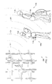
- FIGURE 1 illustrates an example vehicle back-up alarm system 100 according to one embodiment of this disclosure.
- the alarm system 100 is used in a vehicle 102 to warn one or more users 104a-104b that the vehicle 102 has been shifted into a reverse gear or is moving backwards or in the reverse direction.
- Other embodiments of the alarm system 100 may be used without departing from the scope of this disclosure.
- warning sounds produced by the alarms may not be heard by users 104a-104b around a vehicle 102.
- the warning sounds produced by the alarm may not be heard by a hearing-impaired person.
- a person working in a noisy environment such as a jackhammer operator who is wearing earplugs or other noise muffling devices, may have difficulty hearing the warning sounds.
- the inability to hear the warning sounds produced by the back-up alarms may place these or other people in danger.
- the vehicle 102 represents any suitable vehicle.
- the vehicle 102 may represent a vehicle regulated by Occupational Safety and Health Administration (OSHA) regulations, such as 29 C.F.R. ⁇ 1926.601(a) and ⁇ 1926.602 (a) (9)(i). Under these regulations, a regulated vehicle 102 needs an audible alarm system that is activated when the vehicle 102 is placed into reverse gear or is moving backwards or in the reverse direction.
- OSHA Occupational Safety and Health Administration
- a regulated vehicle 102 needs an audible alarm system that is activated when the vehicle 102 is placed into reverse gear or is moving backwards or in the reverse direction.
- the vehicle 102 represents a construction vehicle, although other types of vehicles could be used.
- the vehicle 102 includes a sensor 106 that detects when the vehicle 102 is placed into reverse gear or begins moving backwards.
- the terms “reverse” and “backwards” include total and partial backwards or reverse movement by all or a portion of a vehicle or other object or person.
- the sensor 106 determines that the vehicle 102 has been placed in reverse gear or is moving backwards, the sensor 106 generates an output signal.
- the sensor 106 includes any device or structure, such as an electrical circuit, capable of detecting when a vehicle 102 has been placed in a reverse gear or is moving backwards.
- the sensor may represent a circuit capable of detecting when a driver has shifted a transmission 118 of the vehicle 102 into one of one or more reverse gears.
- the output signal generated by the sensor 106 is received by and activates an audible warning device 108.
- the audible warning device 108 represents any device or devices for producing audible warning sounds, such as a horn or beeper.
- the sounds emitted by the audible warning device 108 may be heard by users 104a-104b around the vehicle 102, which helps the users 104a-104b to avoid the vehicle 102.
- Some of the users 104a-104b around the vehicle 102 may be unable to hear the warning sounds produced by the audible warning device 108.
- the warning sounds may not be heard by a hearing-impaired person or by a person working in a noisy environment, such as a jackhammer operator who is wearing earplugs.
- the vehicle 102 includes a transmitter module 110.
- the transmitter module 110 transmits warning signals 112 to the users 104a-104b.
- the transmitter module 110 includes any hardware, software, firmware, or combination thereof for transmitting warning signals 112.
- the transmitter module 110 transmits radio frequency (“RF") signals 112 to the users 104a-104b.
- RF radio frequency
- the warning signals 112 are received by one or more receiver modules 114a-114b, 116a-116b.
- the receiver modules 114a-114b, 116a-116b are worn or otherwise in the possession of one or more users 104a-104b.
- the receiver modules 114a-114b, 116a-116b notify the users 104a-104b that the vehicle 102 is in reverse gear or is moving backwards.
- the receiver modules 114a-114b may produce visual indicators or stimuli that are detected by the users' sense of sight, and the receiver modules 116a-116b may produce tactile indicators or stimuli that are detected by the users' sense of touch.
- the receiver modules 114a-114b may include flashing lights such as light emitting diodes (LEDs), and the receiver modules 116a-116b may vibrate.
- LEDs light emitting diodes
- Other or additional types of stimuli could be used to warn users 104a-104b, and a single receiver module could provide multiple forms of stimuli to a user.
- the visual and tactile indicators or stimuli produced by the receiver modules 114a-114b, 116a-116b allow the users 104a-104b to determine when the vehicle 102 is in reverse gear or is moving backwards.
- the users 104a-104b may make this determination even when the users 104a-104b cannot hear the warning sounds produced by the audible warning device 108. This helps to improve the safety and effectiveness of the vehicle back-up alarm system 100.
- Each of the receiver modules 114a-114b, 116a-116b includes any hardware, software, firmware, or combination thereof for notifying a user that a vehicle 102 has been placed in reverse gear or is moving backwards.
- each of the receiver modules 114a-114b, 116a-116b may represent a portable module that includes a device to produce vibrations, an electromechanical tapping device, an electrical or visual stimulation device, or any other suitable device.
- the effective range between the transmitter module 110 and receiver modules 114a-114b, 116a-116b may be limited.
- the effective range may be limited to between 30 and 50 meters.
- the receiver modules 114a-114b, 116a-116b may detect signals 112 from vehicles 102 that are closer to the users 104a-104b. This may reduce power consumption and limit or prevent the receiver modules 114a-114b, 116a-116b from receiving signals 112 from vehicles 102 that are not a danger to the users 104a-104b.
- the transmitter module 110 and the audible warning device 108 are illustrated as separate components in the vehicle 102.
- the transmitter module 110 and the audible warning device 108 could also be combined into a single unit. This may allow, for example, the individual transmitter module 110 to be installed on existing vehicles 102 that already have audible warning devices 108, while a combined audible warning device 108/transmitter module 110 can be installed in new vehicles 102.
- FIGURE 1 illustrates one example of a vehicle back-up alarm system 100
- the transmitter module 110 could be placed on any other suitable type of vehicle 102.
- each of the users 104a-104b may use any number of receiver modules 114a-114b, 116a-116b, such as by using a single receiver module.
- FIGURE 2 illustrates an example evacuation alarm system 200 according to one embodiment of this disclosure.
- the alarm system 200 is used to warn one or more users 104a-104b to evacuate a particular location, such as a construction site.
- Other embodiments of the alarm system 200 may be used without departing from the scope of this disclosure.
- the users 104a-104b in FIGURE 2 wear or otherwise possess one or more receiver modules 114a-114b, 116a-116b.
- a transmitter module 202 communicates evacuation signals 204 to the users 104a-104b.
- the receiver modules 114a-114b, 116a-116b receive the evacuation signals 204 and notify the users 104a-104b that the evacuation signals 204 have been received.
- the transmitter module 202 transmits RF signals 204 to the users 104a-104b.
- the effective range between the transmitter module 202 and receiver modules 114a-114b, 116a-116b may extend over the entire area where the users 104a-104b may be located, such as over the entire area of a construction site.
- the transmitter module 202 includes any hardware, software, firmware, or combination thereof for transmitting evacuation signals 204.
- the transmitter module 202 could transmit any other or additional signals to the users 104a-104b.
- the transmitter module 202 could transmit signals to the users 104a-104b indicating that the users' shift is over or that a break period has begun or ended.
- FIGURE 2 illustrates one example of an evacuation alarm system 200
- various changes may be made to FIGURE 2.
- FIGURE 2 illustrates one transmitter module 202 as being placed on a building, one or more transmitter modules 202 could be placed in any suitable location or locations.
- each of the users 104a-104b may use any number of receiver modules 114a-114b, 116a-116b, such as by using a single receiver module.
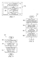
- FIGURE 3 illustrates an example transmitter module 110 according to one embodiment of this disclosure.
- the transmitter module 110 includes a power line 302, a warning signal line 304, an alarm sensor 306, a transmitter controller 308, a transmitter 310, and an antenna 312.
- Other embodiments of the transmitter module 110 may be used without departing from the scope of this disclosure.
- the transmitter module 110 receives operating power through the power line 302.
- the transmitter module 110 receives operating power from the power supply used by the vehicle 102.
- the transmitter module 110 could receive power through the power line 302 from a battery used by the vehicle 102.
- the transmitter module 110 may receive operating power from an internal power supply such as a battery, solar cell, or fuel cell, and the power line 302 would not be needed.
- the transmitter module 110 receives an input signal through the warning signal line 304.
- the input signal indicates that the vehicle 102 has been placed in reverse gear or is moving backwards and that a signal 112, 204 should be transmitted to the users 104a-104b.
- the warning signal line 304 could be coupled to the sensor 106 of FIGURE 1, and the input signal may represent the output signal generated by the sensor 106 that activates the audible warning device 108.
- the term "couple” refers to any direct or indirect communication between two or more components, whether or not those components are in physical contact with one another.
- the warning signal line 304 carries the output signal from the sensor 106 to the transmitter module 110.
- the warning signal line 304 may be coupled directly to the sensor 106 or between the sensor 106 and the audible warning device 108.
- the alarm sensor 306 detects the signal. The alarm sensor 306 then informs the transmitter controller 308 that the input signal has been received.
- the alarm sensor 306 includes any hardware, software, firmware, or combination thereof for detecting a signal received over the warning signal line 304.
- the transmitter controller 308 receives and acknowledges that the alarm sensor 306 has detected the input signal.
- the transmitter controller 308 also generates or causes the transmitter 310 to generate warning signals 112 for one or more receiver modules 114a-114b, 116a-116b.
- the transmitter controller 308 includes any hardware, software, firmware, or combination thereof for controlling the operation of the transmitter module 110.
- the transmitter controller 308 may represent a microprocessor or other processing device, operational amplifiers, memory circuits, or other circuitry.
- the transmitter 310 transmits the warning signals 112 to the users 104a-104b.
- the transmitter 310 includes any hardware, software, firmware, or combination thereof for generating wireless signals.
- the transmitter 310 may represent a RF transmitter.
- the warning signals 112 are communicated to the receiver modules 114a-114, 116a-116b through the antenna 312.
- the antenna 312 represents any suitable structure for transmitting wireless signals.
- the antenna 312 represents a RF antenna.
- the transmitter 310 and antenna 312 represent a low power RF transmitter and antenna that are capable of transmitting the warning signals 112 to the receiver modules 114a-114b, 116a-116b.
- the transmitter 310 may use any suitable modulation scheme to facilitate communication with the receiver modules 114a-114b, 116a-116b.
- the modulation schemes could include On/Off Key (“OOK”) modulation, Frequency Shift Key (“FSK”) modulation, Amplitude Modulation (“AM”), and Frequency Modulation ("FM”).
- the range of the transmitted signals 112 may be controllable, such as by establishing a maximum range of 30 meters, 50 meters, 1000 meters, or other suitable distance or distances.
- FIGURE 3 illustrates a transmitter module 110
- the same or similar structure may be used as the transmitter module 202 in FIGURE 2.
- the alarm sensor 306 may detect any suitable input.
- the alarm sensor 306 could detect when a user has depressed an evacuation button or when a monitoring system has sensed a fire, chemical spill, or other dangerous condition.
- the transmitter module 202 could also be coupled to and receive power from an electrical outlet or other suitable power source.
- the transmitter 310 may generate the evacuation signal 204, and the transmitter module 202 may have any suitable effective range such as 1000 meters.
- FIGURE 3 illustrates one example of a transmitter module 110
- various changes may be made to FIGURE 3.
- the functional division of FIGURE 3 is for illustration only.
- Various components of FIGURE 3 can be combined or omitted and additional components could be added according to particular needs.
- FIGURE 4 illustrates example receiver modules 114a-114b, 116a-116b according to one embodiment of this disclosure.
- the receiver modules 114a-114b, 116a-116b shown in FIGURE 4 are for illustration only. Other embodiments of the receiver modules 114a-114b, 116a-116b may be used without departing from the scope of this disclosure.
- the receiver modules 114a-114b are incorporated into hardhats worn by the users 104a-104b.
- the receiver modules 116a-116b are incorporated into watches, wristbands, or other devices worn around the wrists of the users 104a-104b.
- the receiver modules 114a-114b, 116a-116b use different mechanisms for informing the users 104a-104b that warning signals 112, 204 have been received.
- the receiver modules 114a-114b may include LEDs or other light-generating elements that produce visual stimuli seen by the users 104a-104b.
- the receiver modules 116a-116b may generate mechanical signals, electrical signals, or other tactile stimuli that can be felt by the users 104a-104b. This represents example embodiments of the receiver modules 114a-114b, 116a-116b.
- Each of the receiver modules 114a-114b, 116a-116b could produce one or both of these stimuli and/or other or additional stimuli.
- the receiver modules 114a-114b, 116a-116b are capable of receiving multiple types of signals, such as when the receiver modules 114a-114b, 116a-116b receive both the vehicle back-up warning signals 112 and the evacuation signals 204.
- the receiver modules 114a-114b, 116a-116b could perform different actions depending on the type of signal received. For example, the receiver modules 114a-114b could produce different flashes of light depending on whether the vehicle back-up warning signal 112 or the evacuation signal 204 has been received. Similarly, the receiver modules 116a-116b could produce different vibration patterns depending on whether the vehicle back-up warning signal 112 or the evacuation signal 204 has been received. In this way, the users 104a-104b may easily identify the type of warning signal or other signal that has been received.
- FIGURE 4 illustrates examples of the receiver modules 114a-114b, 116a-116b
- FIGURE 4 illustrates receiver modules embodied in hardhats and wristbands
- the receiver modules could be embodied in any other structure, device, or system.
- the receiver modules could be embodied in mobile telephones, pagers, personal digital assistants, pendants worn around the neck, or clip-on units worn on the users' clothing.
- FIGURE 5 illustrates additional details of one embodiment of a receiver module 114a according to one embodiment of this disclosure.
- the receiver module 114a includes a receiver/antenna 502, a receiver module controller 504, a sense of sight stimulator 506, and a power source 508.
- Other embodiments of the receiver module 114a may be used without departing from the scope of this disclosure.
- the receiver/antenna 502 receives the signals 112, 204 transmitted by the transmitter modules 110, 202.
- the receiver/antenna 502 transfers the received signals 112, 204 to the receiver module controller 504.
- the receiver/antenna 502 may also demodulate the received signals 112, 204 before transferring the received signals 112, 204 to the receiver module controller 504.
- the receiver/antenna 502 represents any hardware, software, firmware, or combination thereof for receiving wireless signals.
- the receiver/antenna 502 may represent a RF receiver and antenna.
- the sensitivity of the receiver/antenna 502 may be established to allow reception up to a maximum distance such as 1000 meters, and the selectivity of the receiver/antenna 502 may be established to minimize reception of unwanted RF or other transmissions.
- the receiver module controller 504 receives the signals 112, 204 provided by the receiver/antenna 502 and acknowledges the signals. In response to the signals 112, 204, the receiver module controller 504 generates an activation signal to activate the stimulator 506. In particular embodiments, the receiver module controller 504 identifies the type of signal received by the receiver module 114a, such as by determining whether a vehicle back-up warning signal 112 or an evacuation signal 204 was received. Based on the type of signal received, the receiver module controller 504 causes the stimulator 506 to operate in a particular mode associated with the type of signal received.
- the receiver module controller 504 includes any hardware, software, firmware, or combination thereof for controlling the operation of the receiver module 114a. As a particular example, the receiver module controller 504 represents a microprocessor or other processing device, operational amplifiers, memory circuits, or other circuitry.
- the stimulator 506 responds to the activation signal from the receiver module controller 504 by producing visual stimuli perceived by the user's sense of sight. This allows the stimulator 506 to warn the user 104a of possible danger, even when the user 104a cannot hear an audible warning signal.
- the stimulator 506 may represent any device or structure for producing visual stimuli that can be detected by a user 104a.
- the stimulator 506 may include one or multiple LEDs capable of generating visual signals.
- the stimulator 506 may include LEDs of different colors corresponding to different types of signals received by the receiver module 114a.
- the receiver/antenna 502, receiver module controller 504, and stimulator 506 are connected internally within the receiver module 114a to the power supply 508.
- the power supply 508 represents any suitable power supply for the receiver module 114a.
- the power supply 508 could represent a battery, fuel cell, solar cell, or other source of operating power.
- the receiver module 114a may be contained in a small lightweight package.
- the receiver package may be of a type of construction to sustain operation in a harsh use environment, such as a construction environment.
- FIGURE 5 illustrates one example of additional details of one embodiment of the receiver module 114a
- various changes may be made to FIGURE 5.
- the functional division of FIGURE 5 is for illustration only.
- Various components of FIGURE 5 can be combined or omitted and additional components could be added according to particular needs.
- FIGURE 6 illustrates an example placement of components of a receiver module 114a according to one embodiment of this disclosure.
- FIGURE 6 illustrates placement of the components illustrated in FIGURE 5 within a hardhat for use by a user 104a.
- Other placements of components may be used in the receiver module 114a without departing from the scope of this disclosure.
- the sense of sight stimulator 506 generates visual signals that can be seen by a user 104a.
- the sense of sight stimulator 506 is located generally at the front of the hardhat. In this way, the sense of sight stimulator 506 is located within a field of view of the user 104a.
- the sense of sight stimulator 506 is located on a rim 602 of the hardhat and to one side of the rim 602. This represents one example placement of the sense of sight stimulator 506 in the hardhat.
- the sense of sight stimulator 506 could be placed at any other suitable location in the hardhat.
- FIGURE 6 shows all three components 502, 504, 508 integrated into a single unit in the hardhat, the various components 502, 504, 508 could reside separate from each other in the hardhat.
- FIGURE 6 illustrates one example of the placement of components of a receiver module 114a
- various changes may be made to FIGURE 6.
- the various components 502-508 may be placed in any other suitable location or locations.
- FIGURE 7 illustrates additional details of another embodiment of a receiver module 116a according to one embodiment of this disclosure.
- the receiver module 116a includes a receiver/antenna 702, a receiver module controller 704, a sense of touch stimulator 706, and a power source 708.
- Other embodiments of the receiver module 116a may be used without departing from the scope of this disclosure.
- the receiver/antenna 702, receiver module controller 704, and power source 708 may be the same as or similar to the receiver/antenna 502, receiver module controller 504, and power source 508, respectively, of FIGURE 5.
- the sense of touch stimulator 706 is controlled by the receiver module controller 704 and produces mechanical, electrical, or other signals perceived by the user's sense of touch. This allows the stimulator 706 to warn the user 104a of possible danger.
- the stimulator 706 may represent any suitable device or structure for producing tactile signals that can be detected by a user 104a.
- the stimulator 706 may include a device to produce vibrations, an electromechanical tapping device, or an electrical stimulation device.
- the stimulator 706 may be similar to the stimulators used on pagers, mobile telephones, and other mobile devices to notify a user of an incoming page, call, or other communication.
- the stimulator 706 produces different types of tactile signals corresponding to different types of wireless warning signals received by the receiver module 116a.
- the receiver module 116a may be contained in a small lightweight package, such as a wristband, that allows convenient contact with the user's skin.
- the stimulator 706 may be placed in the package such that it provides a maximum stimulation to the user's sense of touch.
- the receiver package may be of a type of construction to sustain operation in a harsh use environment, such as a construction environment, although other possible receiver packages may be used.
- FIGURE 7 illustrates additional details of another embodiment of the receiver module 116a
- various changes may be made to FIGURE 7.
- the functional division of FIGURE 7 is for illustration only.
- Various components of FIGURE 7 can be combined or omitted and additional components could be added according to particular needs.
- FIGURE 8 illustrates an example method 800 for generating a vehicle back-up alarm according to one embodiment of this disclosure.
- the method 800 is described with respect to the vehicle back-up alarm system 100 shown in FIGURE 1.
- the method 800 could also be used with any other suitable vehicle back-up alarm system.
- the vehicle back-up alarm system 100 detects a vehicle entering a reverse gear or moving backwards or in the reverse direction at step 802. This may include, for example, the sensor 106 determining whether the vehicle 102 has been placed into reverse gear or has begun to move backwards.
- the vehicle back-up alarm system 100 generates audible warning sounds at step 804. This may include, for example, the sensor 106 generating an output signal that triggers the audible warning device 108. This may also include the audible warning device 108 generating any suitable warning sounds.
- the vehicle back-up alarm system 100 generates a wireless warning signal at step 806.
- This may include, for example, the alarm sensor 306 in the transmitter module 110 detecting the output signal produced by the sensor 106.
- This may also include the transmitter controller 308 generating or causing the transmitter 310 to generate a RF signal or other signal 112.
- the vehicle back-up alarm system 100 communicates the warning signal to any receiver modules in the vicinity of the vehicle 102 at step 808.
- This may include, for example, the transmitter 310 in the transmitter module 110 communicating the warning signal 112 through the antenna 312.
- This may also include the transmitter module 110 communicating the warning signal 112 to any receiver modules 114a-114b, 116a-116b within a specified area around the vehicle 102, such as to any receiver modules 114a-114b, 116a-116b within 30 to 50 meters of the vehicle 102.
- FIGURE 8 illustrates one example of a method 800 for generating a vehicle back-up alarm
- the warning signal may be communicated over a wide area and need not be limited to the vicinity near a vehicle 102.
- the vehicle back-up alarm system 100 may only transmit a wireless warning signal and need not generate audible warning sounds.
- FIGURE 9 illustrates an example method 900 for providing a warning indicator to a user according to one embodiment of this disclosure.
- the method 900 is described with respect to the receiver modules 114a-114b, 116a-116b of FIGURES 5 and 7 operating in the systems 100, 200 of FIGURES 1 and 2.
- the method 900 could also be used by any other suitable receiver module and in any other suitable system.
- the receiver module 114a-114b, 116a-116b receives a warning signal at step 902. This may include, for example, the receiver/antenna 502, 702 receiving a warning signal 112, 204 transmitted by a transmitter module 110, 202. This may also include the receiver/antenna 502, 702 forwarding the warning signal to the receiver module controller 504, 704.
- the receiver module 114a-114b, 116a-116b identifies the type of warning signal received at step 904. This may include, for example, the receiver module controller 504, 704 determining whether the received warning signal represents a vehicle back-up warning signal 112 or an evacuation signal 204.
- the receiver module 114a-114b, 116a-116b generates a perceptible indicator for a user at step 906.
- This may include, for example, the receiver module controller 504, 704 triggering a sense of sight stimulator 506 and/or a sense of touch stimulator 706.
- This may also include the receiver module controller 504, 704 triggering the stimulator 506 and/or the stimulator 706 differently based on the type of warning signal received.
- FIGURE 9 illustrates one example of a method 900 for providing a warning indicator to a user
- various changes may be made to FIGURE 9.
- the receiver module 114a-114b, 116a-116b could only be able to provide a single indicator or stimulus to a user, and the receiver module 114a-114b, 116a-116b need not identify the type of warning signal received.
- controller means any device, system, or part thereof that controls at least one operation.
- a controller may be implemented in hardware, software, firmware, or combination thereof. It should be noted that the functionality associated with any particular controller may be centralized or distributed, whether locally or remotely.
Abstract
Description
- This patent application claims priority under 35 U.S.C. § 119(e) to U.S. Provisional Application No. 60/498,374 filed on August 26, 2003 and which is hereby incorporated by reference.
- This patent application is related to U.S. Patent Application No. 10/818,095 entitled "SYSTEM, METHOD, AND RECEIVER MODULE FOR ALERTING USERS OF WARNING SIGNALS" filed on APRIL 5, 2004 and which is hereby incorporated by reference.
- This disclosure relates generally to vehicle alarm systems and more specifically to a vehicle back-up alarm system, vehicle, transmitter module, and method.
- Different vehicles often include different types of "back-up" alarms. A typical back-up alarm warns when a vehicle has been shifted into reverse gear or is actually moving backwards. A conventional back-up alarm includes an audible device placed on a construction vehicle or other vehicle, such as a horn placed on a forklift, dump truck, or golf cart. The audible device produces warning sounds when the vehicle is placed in reverse gear or begins moving backwards.
- This disclosure provides a vehicle back-up alarm system, vehicle, transmitter module, and method.
- In one aspect, a vehicle back-up alarm system includes a sensor capable of determining when a vehicle is at least one of in a reverse gear and moving backwards. The vehicle back-up alarm system also includes a transmitter module capable of transmitting a warning signal in response to the sensor determining that the vehicle is at least one of in the reverse gear and moving backwards.
- In another aspect, a method includes determining when a vehicle is at least one of in a reverse gear and moving backwards. The method also includes transmitting a wireless warning signal in response to determining that the vehicle is at least one of in the reverse gear and moving backwards.
- In yet another aspect, a transmitter module includes an alarm sensor capable of detecting that a sensor has determined that a vehicle is at least one of in a reverse gear and moving backwards. The transmitter module also includes a transmitter capable of transmitting a warning signal in response to the alarm sensor detecting that the sensor has determined that the vehicle is at least one of in the reverse gear and moving backwards.
- In still another embodiment, a vehicle includes a transmission that has a reverse gear. The vehicle also includes a vehicle back-up alarm system that is capable of determining when the vehicle is at least one of in the reverse gear and moving backwards. The vehicle back-up alarm system is also capable of transmitting a warning signal in response to determining that the vehicle is at least one of in the reverse gear and moving backwards.
- Other technical features may be readily apparent to one skilled in the art from the following figures, descriptions, and claims.
- For a more complete understanding of this disclosure and its features, reference is now made to the following description taken in conjunction with the accompanying drawings, in which:
- FIGURE 1 illustrates an example vehicle back-up alarm system according to one embodiment of this disclosure;
- FIGURE 2 illustrates an example evacuation alarm system according to one embodiment of this disclosure;
- FIGURE 3 illustrates an example transmitter module according to one embodiment of this disclosure;
- FIGURE 4 illustrates example receiver modules according to one embodiment of this disclosure;
- FIGURE 5 illustrates additional details of one embodiment of a receiver module according to one embodiment of this disclosure;
- FIGURE 6 illustrates an example placement of components of a receiver module according to one embodiment of this disclosure;
- FIGURE 7 illustrates additional details of another embodiment of a receiver module according to one embodiment of this disclosure;
- FIGURE 8 illustrates an example method for generating a vehicle back-up alarm according to one embodiment of this disclosure; and
- FIGURE 9 illustrates an example method for providing a warning indicator to a user according to one embodiment of this disclosure.
- FIGURE 1 illustrates an example vehicle back-up alarm system 100 according to one embodiment of this disclosure. In the illustrated example, the alarm system 100 is used in a
vehicle 102 to warn one ormore users 104a-104b that thevehicle 102 has been shifted into a reverse gear or is moving backwards or in the reverse direction. Other embodiments of the alarm system 100 may be used without departing from the scope of this disclosure. - A problem with conventional vehicle back-up alarms is that warning sounds produced by the alarms may not be heard by
users 104a-104b around avehicle 102. For example, the warning sounds produced by the alarm may not be heard by a hearing-impaired person. As another example, a person working in a noisy environment, such as a jackhammer operator who is wearing earplugs or other noise muffling devices, may have difficulty hearing the warning sounds. The inability to hear the warning sounds produced by the back-up alarms may place these or other people in danger. - The
vehicle 102 represents any suitable vehicle. As an example, thevehicle 102 may represent a vehicle regulated by Occupational Safety and Health Administration (OSHA) regulations, such as 29 C.F.R. § 1926.601(a) and § 1926.602 (a) (9)(i). Under these regulations, a regulatedvehicle 102 needs an audible alarm system that is activated when thevehicle 102 is placed into reverse gear or is moving backwards or in the reverse direction. In FIGURE 1, thevehicle 102 represents a construction vehicle, although other types of vehicles could be used. - In this example, the
vehicle 102 includes asensor 106 that detects when thevehicle 102 is placed into reverse gear or begins moving backwards. In this document, the terms "reverse" and "backwards" include total and partial backwards or reverse movement by all or a portion of a vehicle or other object or person. When thesensor 106 determines that thevehicle 102 has been placed in reverse gear or is moving backwards, thesensor 106 generates an output signal. Thesensor 106 includes any device or structure, such as an electrical circuit, capable of detecting when avehicle 102 has been placed in a reverse gear or is moving backwards. As a particular example, the sensor may represent a circuit capable of detecting when a driver has shifted atransmission 118 of thevehicle 102 into one of one or more reverse gears. - The output signal generated by the
sensor 106 is received by and activates anaudible warning device 108. Theaudible warning device 108 represents any device or devices for producing audible warning sounds, such as a horn or beeper. The sounds emitted by theaudible warning device 108 may be heard byusers 104a-104b around thevehicle 102, which helps theusers 104a-104b to avoid thevehicle 102. - Some of the
users 104a-104b around thevehicle 102 may be unable to hear the warning sounds produced by theaudible warning device 108. For example, the warning sounds may not be heard by a hearing-impaired person or by a person working in a noisy environment, such as a jackhammer operator who is wearing earplugs. - To more effectively warn the
users 104a-104b that thevehicle 102 has been placed in reverse gear or is moving backwards, thevehicle 102 includes atransmitter module 110. When thesensor 106 detects that thevehicle 102 has been placed in reverse gear or is moving backwards or when theaudible warning device 108 is activated, thetransmitter module 110 transmitswarning signals 112 to theusers 104a-104b. Thetransmitter module 110 includes any hardware, software, firmware, or combination thereof for transmittingwarning signals 112. In some embodiments, thetransmitter module 110 transmits radio frequency ("RF") signals 112 to theusers 104a-104b. - The
warning signals 112 are received by one ormore receiver modules 114a-114b, 116a-116b. Thereceiver modules 114a-114b, 116a-116b are worn or otherwise in the possession of one ormore users 104a-104b. Thereceiver modules 114a-114b, 116a-116b notify theusers 104a-104b that thevehicle 102 is in reverse gear or is moving backwards. As an example, thereceiver modules 114a-114b may produce visual indicators or stimuli that are detected by the users' sense of sight, and thereceiver modules 116a-116b may produce tactile indicators or stimuli that are detected by the users' sense of touch. As particular examples, thereceiver modules 114a-114b may include flashing lights such as light emitting diodes (LEDs), and thereceiver modules 116a-116b may vibrate. Other or additional types of stimuli (including audio stimuli) could be used to warnusers 104a-104b, and a single receiver module could provide multiple forms of stimuli to a user. - The visual and tactile indicators or stimuli produced by the
receiver modules 114a-114b, 116a-116b allow theusers 104a-104b to determine when thevehicle 102 is in reverse gear or is moving backwards. Theusers 104a-104b may make this determination even when theusers 104a-104b cannot hear the warning sounds produced by theaudible warning device 108. This helps to improve the safety and effectiveness of the vehicle back-up alarm system 100. - Each of the
receiver modules 114a-114b, 116a-116b includes any hardware, software, firmware, or combination thereof for notifying a user that avehicle 102 has been placed in reverse gear or is moving backwards. As particular examples, each of thereceiver modules 114a-114b, 116a-116b may represent a portable module that includes a device to produce vibrations, an electromechanical tapping device, an electrical or visual stimulation device, or any other suitable device. - In particular embodiments, the effective range between the
transmitter module 110 andreceiver modules 114a-114b, 116a-116b may be limited. For example, the effective range may be limited to between 30 and 50 meters. In this way, thereceiver modules 114a-114b, 116a-116b may detectsignals 112 fromvehicles 102 that are closer to theusers 104a-104b. This may reduce power consumption and limit or prevent thereceiver modules 114a-114b, 116a-116b from receivingsignals 112 fromvehicles 102 that are not a danger to theusers 104a-104b. - In FIGURE 1, the
transmitter module 110 and theaudible warning device 108 are illustrated as separate components in thevehicle 102. Thetransmitter module 110 and theaudible warning device 108 could also be combined into a single unit. This may allow, for example, theindividual transmitter module 110 to be installed on existingvehicles 102 that already haveaudible warning devices 108, while a combinedaudible warning device 108/transmitter module 110 can be installed innew vehicles 102. - Although FIGURE 1 illustrates one example of a vehicle back-up alarm system 100, various changes may be made to FIGURE 1. For example, the
transmitter module 110 could be placed on any other suitable type ofvehicle 102. Also, each of theusers 104a-104b may use any number ofreceiver modules 114a-114b, 116a-116b, such as by using a single receiver module. - FIGURE 2 illustrates an example
evacuation alarm system 200 according to one embodiment of this disclosure. In the illustrated example, thealarm system 200 is used to warn one ormore users 104a-104b to evacuate a particular location, such as a construction site. Other embodiments of thealarm system 200 may be used without departing from the scope of this disclosure. - As with the vehicle back-up alarm system 100 of FIGURE 1, the
users 104a-104b in FIGURE 2 wear or otherwise possess one ormore receiver modules 114a-114b, 116a-116b. In this example, atransmitter module 202 communicates evacuation signals 204 to theusers 104a-104b. Thereceiver modules 114a-114b, 116a-116b receive the evacuation signals 204 and notify theusers 104a-104b that the evacuation signals 204 have been received. In some embodiments, thetransmitter module 202 transmits RF signals 204 to theusers 104a-104b. In particular embodiments, the effective range between thetransmitter module 202 andreceiver modules 114a-114b, 116a-116b may extend over the entire area where theusers 104a-104b may be located, such as over the entire area of a construction site. Thetransmitter module 202 includes any hardware, software, firmware, or combination thereof for transmitting evacuation signals 204. - Although this has described the
transmitter module 202 as transmittingevacuation signals 204 to theusers 104a-104b, thetransmitter module 202 could transmit any other or additional signals to theusers 104a-104b. For example, thetransmitter module 202 could transmit signals to theusers 104a-104b indicating that the users' shift is over or that a break period has begun or ended. - Although FIGURE 2 illustrates one example of an
evacuation alarm system 200, various changes may be made to FIGURE 2. For example, while FIGURE 2 illustrates onetransmitter module 202 as being placed on a building, one ormore transmitter modules 202 could be placed in any suitable location or locations. Also, each of theusers 104a-104b may use any number ofreceiver modules 114a-114b, 116a-116b, such as by using a single receiver module. - FIGURE 3 illustrates an
example transmitter module 110 according to one embodiment of this disclosure. In the illustrated example, thetransmitter module 110 includes apower line 302, awarning signal line 304, analarm sensor 306, atransmitter controller 308, atransmitter 310, and anantenna 312. Other embodiments of thetransmitter module 110 may be used without departing from the scope of this disclosure. - The
transmitter module 110 receives operating power through thepower line 302. In some embodiments, thetransmitter module 110 receives operating power from the power supply used by thevehicle 102. As a particular example, thetransmitter module 110 could receive power through thepower line 302 from a battery used by thevehicle 102. In other embodiments, thetransmitter module 110 may receive operating power from an internal power supply such as a battery, solar cell, or fuel cell, and thepower line 302 would not be needed. - The
transmitter module 110 receives an input signal through thewarning signal line 304. The input signal indicates that thevehicle 102 has been placed in reverse gear or is moving backwards and that asignal users 104a-104b. For example, thewarning signal line 304 could be coupled to thesensor 106 of FIGURE 1, and the input signal may represent the output signal generated by thesensor 106 that activates theaudible warning device 108. In this document, the term "couple" refers to any direct or indirect communication between two or more components, whether or not those components are in physical contact with one another. In this example, thewarning signal line 304 carries the output signal from thesensor 106 to thetransmitter module 110. Thewarning signal line 304 may be coupled directly to thesensor 106 or between thesensor 106 and theaudible warning device 108. - When the
transmitter module 110 receives an input signal over thewarning signal line 304, thealarm sensor 306 detects the signal. Thealarm sensor 306 then informs thetransmitter controller 308 that the input signal has been received. Thealarm sensor 306 includes any hardware, software, firmware, or combination thereof for detecting a signal received over thewarning signal line 304. - The
transmitter controller 308 receives and acknowledges that thealarm sensor 306 has detected the input signal. Thetransmitter controller 308 also generates or causes thetransmitter 310 to generatewarning signals 112 for one ormore receiver modules 114a-114b, 116a-116b. Thetransmitter controller 308 includes any hardware, software, firmware, or combination thereof for controlling the operation of thetransmitter module 110. As a particular example, thetransmitter controller 308 may represent a microprocessor or other processing device, operational amplifiers, memory circuits, or other circuitry. - The
transmitter 310 transmits the warning signals 112 to theusers 104a-104b. Thetransmitter 310 includes any hardware, software, firmware, or combination thereof for generating wireless signals. As a particular example, thetransmitter 310 may represent a RF transmitter. - The warning signals 112 are communicated to the
receiver modules 114a-114, 116a-116b through theantenna 312. Theantenna 312 represents any suitable structure for transmitting wireless signals. As a particular example, theantenna 312 represents a RF antenna. - In particular embodiments, the
transmitter 310 andantenna 312 represent a low power RF transmitter and antenna that are capable of transmitting the warning signals 112 to thereceiver modules 114a-114b, 116a-116b. Also, thetransmitter 310 may use any suitable modulation scheme to facilitate communication with thereceiver modules 114a-114b, 116a-116b. As particular examples, the modulation schemes could include On/Off Key ("OOK") modulation, Frequency Shift Key ("FSK") modulation, Amplitude Modulation ("AM"), and Frequency Modulation ("FM"). In addition, the range of the transmitted signals 112 may be controllable, such as by establishing a maximum range of 30 meters, 50 meters, 1000 meters, or other suitable distance or distances. - While FIGURE 3 illustrates a
transmitter module 110, the same or similar structure may be used as thetransmitter module 202 in FIGURE 2. In thetransmitter module 202, thealarm sensor 306 may detect any suitable input. For example, thealarm sensor 306 could detect when a user has depressed an evacuation button or when a monitoring system has sensed a fire, chemical spill, or other dangerous condition. Thetransmitter module 202 could also be coupled to and receive power from an electrical outlet or other suitable power source. In addition, thetransmitter 310 may generate theevacuation signal 204, and thetransmitter module 202 may have any suitable effective range such as 1000 meters. - Although FIGURE 3 illustrates one example of a
transmitter module 110, various changes may be made to FIGURE 3. For example, the functional division of FIGURE 3 is for illustration only. Various components of FIGURE 3 can be combined or omitted and additional components could be added according to particular needs. - FIGURE 4 illustrates
example receiver modules 114a-114b, 116a-116b according to one embodiment of this disclosure. Thereceiver modules 114a-114b, 116a-116b shown in FIGURE 4 are for illustration only. Other embodiments of thereceiver modules 114a-114b, 116a-116b may be used without departing from the scope of this disclosure. - As shown in FIGURE 4, the
receiver modules 114a-114b are incorporated into hardhats worn by theusers 104a-104b. Thereceiver modules 116a-116b are incorporated into watches, wristbands, or other devices worn around the wrists of theusers 104a-104b. - In some embodiments, the
receiver modules 114a-114b, 116a-116b use different mechanisms for informing theusers 104a-104b that warning signals 112, 204 have been received. For example, thereceiver modules 114a-114b may include LEDs or other light-generating elements that produce visual stimuli seen by theusers 104a-104b. Thereceiver modules 116a-116b may generate mechanical signals, electrical signals, or other tactile stimuli that can be felt by theusers 104a-104b. This represents example embodiments of thereceiver modules 114a-114b, 116a-116b. Each of thereceiver modules 114a-114b, 116a-116b could produce one or both of these stimuli and/or other or additional stimuli. - In particular embodiments, the
receiver modules 114a-114b, 116a-116b are capable of receiving multiple types of signals, such as when thereceiver modules 114a-114b, 116a-116b receive both the vehicle back-up warning signals 112 and the evacuation signals 204. In these embodiments, thereceiver modules 114a-114b, 116a-116b could perform different actions depending on the type of signal received. For example, thereceiver modules 114a-114b could produce different flashes of light depending on whether the vehicle back-upwarning signal 112 or theevacuation signal 204 has been received. Similarly, thereceiver modules 116a-116b could produce different vibration patterns depending on whether the vehicle back-upwarning signal 112 or theevacuation signal 204 has been received. In this way, theusers 104a-104b may easily identify the type of warning signal or other signal that has been received. - Although FIGURE 4 illustrates examples of the
receiver modules 114a-114b, 116a-116b, various changes may be made to FIGURE 4. For example, while FIGURE 4 illustrates receiver modules embodied in hardhats and wristbands, the receiver modules could be embodied in any other structure, device, or system. As particular examples, the receiver modules could be embodied in mobile telephones, pagers, personal digital assistants, pendants worn around the neck, or clip-on units worn on the users' clothing. - FIGURE 5 illustrates additional details of one embodiment of a
receiver module 114a according to one embodiment of this disclosure. In the illustrated example, thereceiver module 114a includes a receiver/antenna 502, areceiver module controller 504, a sense ofsight stimulator 506, and apower source 508. Other embodiments of thereceiver module 114a may be used without departing from the scope of this disclosure. - The receiver/
antenna 502 receives thesignals transmitter modules antenna 502 transfers the received signals 112, 204 to thereceiver module controller 504. The receiver/antenna 502 may also demodulate the received signals 112, 204 before transferring the received signals 112, 204 to thereceiver module controller 504. The receiver/antenna 502 represents any hardware, software, firmware, or combination thereof for receiving wireless signals. As a particular example, the receiver/antenna 502 may represent a RF receiver and antenna. Also, the sensitivity of the receiver/antenna 502 may be established to allow reception up to a maximum distance such as 1000 meters, and the selectivity of the receiver/antenna 502 may be established to minimize reception of unwanted RF or other transmissions. - The
receiver module controller 504 receives thesignals antenna 502 and acknowledges the signals. In response to thesignals receiver module controller 504 generates an activation signal to activate thestimulator 506. In particular embodiments, thereceiver module controller 504 identifies the type of signal received by thereceiver module 114a, such as by determining whether a vehicle back-upwarning signal 112 or anevacuation signal 204 was received. Based on the type of signal received, thereceiver module controller 504 causes thestimulator 506 to operate in a particular mode associated with the type of signal received. Thereceiver module controller 504 includes any hardware, software, firmware, or combination thereof for controlling the operation of thereceiver module 114a. As a particular example, thereceiver module controller 504 represents a microprocessor or other processing device, operational amplifiers, memory circuits, or other circuitry. - The
stimulator 506 responds to the activation signal from thereceiver module controller 504 by producing visual stimuli perceived by the user's sense of sight. This allows thestimulator 506 to warn theuser 104a of possible danger, even when theuser 104a cannot hear an audible warning signal. Thestimulator 506 may represent any device or structure for producing visual stimuli that can be detected by auser 104a. For example, thestimulator 506 may include one or multiple LEDs capable of generating visual signals. As a particular example, thestimulator 506 may include LEDs of different colors corresponding to different types of signals received by thereceiver module 114a. - The receiver/
antenna 502,receiver module controller 504, andstimulator 506 are connected internally within thereceiver module 114a to thepower supply 508. Thepower supply 508 represents any suitable power supply for thereceiver module 114a. For example, thepower supply 508 could represent a battery, fuel cell, solar cell, or other source of operating power. - For portability and usability, the
receiver module 114a may be contained in a small lightweight package. The receiver package may be of a type of construction to sustain operation in a harsh use environment, such as a construction environment. - Although FIGURE 5 illustrates one example of additional details of one embodiment of the
receiver module 114a, various changes may be made to FIGURE 5. For example, the functional division of FIGURE 5 is for illustration only. Various components of FIGURE 5 can be combined or omitted and additional components could be added according to particular needs. - FIGURE 6 illustrates an example placement of components of a
receiver module 114a according to one embodiment of this disclosure. In particular, FIGURE 6 illustrates placement of the components illustrated in FIGURE 5 within a hardhat for use by auser 104a. Other placements of components may be used in thereceiver module 114a without departing from the scope of this disclosure. - As shown in FIGURE 6, the sense of
sight stimulator 506 generates visual signals that can be seen by auser 104a. In the illustrated example, the sense ofsight stimulator 506 is located generally at the front of the hardhat. In this way, the sense ofsight stimulator 506 is located within a field of view of theuser 104a. - In this example, the sense of
sight stimulator 506 is located on arim 602 of the hardhat and to one side of therim 602. This represents one example placement of the sense ofsight stimulator 506 in the hardhat. The sense ofsight stimulator 506 could be placed at any other suitable location in the hardhat. - The remaining
components components various components - Although FIGURE 6 illustrates one example of the placement of components of a
receiver module 114a, various changes may be made to FIGURE 6. For example, the various components 502-508 may be placed in any other suitable location or locations. - FIGURE 7 illustrates additional details of another embodiment of a
receiver module 116a according to one embodiment of this disclosure. In the illustrated example, thereceiver module 116a includes a receiver/antenna 702, areceiver module controller 704, a sense oftouch stimulator 706, and apower source 708. Other embodiments of thereceiver module 116a may be used without departing from the scope of this disclosure. - The receiver/
antenna 702,receiver module controller 704, andpower source 708 may be the same as or similar to the receiver/antenna 502,receiver module controller 504, andpower source 508, respectively, of FIGURE 5. - The sense of
touch stimulator 706 is controlled by thereceiver module controller 704 and produces mechanical, electrical, or other signals perceived by the user's sense of touch. This allows thestimulator 706 to warn theuser 104a of possible danger. Thestimulator 706 may represent any suitable device or structure for producing tactile signals that can be detected by auser 104a. For example, thestimulator 706 may include a device to produce vibrations, an electromechanical tapping device, or an electrical stimulation device. As a particular example, thestimulator 706 may be similar to the stimulators used on pagers, mobile telephones, and other mobile devices to notify a user of an incoming page, call, or other communication. In particular embodiments, thestimulator 706 produces different types of tactile signals corresponding to different types of wireless warning signals received by thereceiver module 116a. - For portability and usability, the
receiver module 116a may be contained in a small lightweight package, such as a wristband, that allows convenient contact with the user's skin. Thestimulator 706 may be placed in the package such that it provides a maximum stimulation to the user's sense of touch. The receiver package may be of a type of construction to sustain operation in a harsh use environment, such as a construction environment, although other possible receiver packages may be used. - Although FIGURE 7 illustrates additional details of another embodiment of the
receiver module 116a, various changes may be made to FIGURE 7. For example, the functional division of FIGURE 7 is for illustration only. Various components of FIGURE 7 can be combined or omitted and additional components could be added according to particular needs. - FIGURE 8 illustrates an
example method 800 for generating a vehicle back-up alarm according to one embodiment of this disclosure. For ease of illustration and explanation, themethod 800 is described with respect to the vehicle back-up alarm system 100 shown in FIGURE 1. Themethod 800 could also be used with any other suitable vehicle back-up alarm system. - The vehicle back-up alarm system 100 detects a vehicle entering a reverse gear or moving backwards or in the reverse direction at
step 802. This may include, for example, thesensor 106 determining whether thevehicle 102 has been placed into reverse gear or has begun to move backwards. - The vehicle back-up alarm system 100 generates audible warning sounds at
step 804. This may include, for example, thesensor 106 generating an output signal that triggers theaudible warning device 108. This may also include theaudible warning device 108 generating any suitable warning sounds. - The vehicle back-up alarm system 100 generates a wireless warning signal at
step 806. This may include, for example, thealarm sensor 306 in thetransmitter module 110 detecting the output signal produced by thesensor 106. This may also include thetransmitter controller 308 generating or causing thetransmitter 310 to generate a RF signal orother signal 112. - The vehicle back-up alarm system 100 communicates the warning signal to any receiver modules in the vicinity of the
vehicle 102 atstep 808. This may include, for example, thetransmitter 310 in thetransmitter module 110 communicating thewarning signal 112 through theantenna 312. This may also include thetransmitter module 110 communicating thewarning signal 112 to anyreceiver modules 114a-114b, 116a-116b within a specified area around thevehicle 102, such as to anyreceiver modules 114a-114b, 116a-116b within 30 to 50 meters of thevehicle 102. - Although FIGURE 8 illustrates one example of a
method 800 for generating a vehicle back-up alarm, various changes may be made to FIGURE 8. For example, the warning signal may be communicated over a wide area and need not be limited to the vicinity near avehicle 102. Also, the vehicle back-up alarm system 100 may only transmit a wireless warning signal and need not generate audible warning sounds. - FIGURE 9 illustrates an
example method 900 for providing a warning indicator to a user according to one embodiment of this disclosure. For ease of illustration and explanation, themethod 900 is described with respect to thereceiver modules 114a-114b, 116a-116b of FIGURES 5 and 7 operating in thesystems 100, 200 of FIGURES 1 and 2. Themethod 900 could also be used by any other suitable receiver module and in any other suitable system. - The
receiver module 114a-114b, 116a-116b receives a warning signal atstep 902. This may include, for example, the receiver/antenna warning signal transmitter module antenna receiver module controller - The
receiver module 114a-114b, 116a-116b identifies the type of warning signal received atstep 904. This may include, for example, thereceiver module controller warning signal 112 or anevacuation signal 204. - The
receiver module 114a-114b, 116a-116b generates a perceptible indicator for a user atstep 906. This may include, for example, thereceiver module controller sight stimulator 506 and/or a sense oftouch stimulator 706. This may also include thereceiver module controller stimulator 506 and/or thestimulator 706 differently based on the type of warning signal received. - Although FIGURE 9 illustrates one example of a
method 900 for providing a warning indicator to a user, various changes may be made to FIGURE 9. For example, thereceiver module 114a-114b, 116a-116b could only be able to provide a single indicator or stimulus to a user, and thereceiver module 114a-114b, 116a-116b need not identify the type of warning signal received. - It may be advantageous to set forth definitions of certain words and phrases that have been used within this patent document. The terms "include" and "comprise," as well as derivatives thereof, mean inclusion without limitation. The term "or" is inclusive, meaning and/or. The phrases "associated with" and "associated therewith," as well as derivatives thereof, may mean to include, be included within, interconnect with, contain, be contained within, connect to or with, couple to or with, be communicable with, cooperate with, interleave, juxtapose, be proximate to, be bound to or with, have, have a property of, or the like. The term "controller" means any device, system, or part thereof that controls at least one operation. A controller may be implemented in hardware, software, firmware, or combination thereof. It should be noted that the functionality associated with any particular controller may be centralized or distributed, whether locally or remotely.
- While this disclosure has described certain embodiments and generally associated methods, alterations and permutations of these embodiments and methods will be apparent to those skilled in the art. Accordingly, the above description of example embodiments does not define or constrain this disclosure. Other changes, substitutions, and alterations are also possible without departing from the spirit and scope of this disclosure, as defined by the following claims.
Claims (23)
- A vehicle back-up alarm system, comprising:a sensor capable of determining when a vehicle is at least one of: in a reverse gear and moving backwards; anda transmitter module capable of transmitting a warning signal in response to the sensor determining that the vehicle is at least one of: in the reverse gear and moving backwards.
- The vehicle back-up alarm system of Claim 1, further comprising an audible warning device capable of generating audible warning sounds in response to the sensor determining that the vehicle is at least one of: in the reverse gear and moving backwards.
- The vehicle back-up alarm system of Claim 1, wherein:the sensor is capable of generating an output signal in response to determining that the vehicle is at least one of: in the reverse gear and moving backwards; andthe transmitter module comprises an alarm sensor capable of detecting the output signal.
- The vehicle back-up alarm system of Claim 3, wherein the transmitter module further comprises a controller capable of causing a transmitter to communicate the warning signal in response to the alarm sensor detecting the output signal.
- The vehicle back-up alarm system of Claim 4, wherein the transmitter comprises a radio frequency transmitter.
- The vehicle back-up alarm system of Claim 1, wherein the transmitter module is capable of transmitting the warning signal to one or more receiver modules in a vicinity of the vehicle.
- The vehicle back-up alarm system of Claim 1, wherein the transmitter module is capable of transmitting the warning signal to one or more receiver modules within 50 meters of the vehicle.
- A method, comprising:determining when a vehicle is at least one of: in a reverse gear and moving backwards; andtransmitting a wireless warning signal in response to determining that the vehicle is at least one of: in the reverse gear and moving backwards.
- The method of Claim 8, further comprising generating audible warning sounds in response to determining that the vehicle is at least one of: in the reverse gear and moving backwards.
- The method of Claim 8, wherein:the determining step comprises generating an output signal when the vehicle is at least one of: in the reverse gear and moving backwards; andthe transmitting step comprises:detecting the output signal;generating the warning signal in response to detecting the output signal; andwirelessly communicating the warning signal.
- The method of Claim 8, wherein the transmitting step comprises transmitting a radio frequency warning signal.
- A transmitter module, comprising:an alarm sensor capable of detecting that a sensor has determined that a vehicle is at least one of: in a reverse gear and moving backwards; anda transmitter capable of transmitting a warning signal in response to the alarm sensor detecting that the sensor has determined that the vehicle is at least one of: in the reverse gear and moving backwards.
- The transmitter module of Claim 12, wherein:the sensor is capable of generating an output signal in response to determining that the vehicle is at least one of: in the reverse gear and moving backwards; andthe alarm sensor is capable of detecting the output signal.
- The transmitter module of Claim 13, further comprising a controller capable of causing the transmitter to communicate the warning signal in response to the alarm sensor detecting the output signal.
- The transmitter module of Claim 13, wherein the alarm sensor is at least one of: coupled directly to the sensor and coupled between the sensor and an audible warning device, the audible warning device capable of generating audible warning sounds in response to the output signal.
- A vehicle, comprising:a transmission comprising a reverse gear; anda vehicle back-up alarm system capable of:determining when the vehicle is at least one of: in the reverse gear and moving backwards; andtransmitting a warning signal in response to determining that the vehicle is at least one of: in the reverse gear and moving backwards.
- The vehicle of Claim 16, wherein the vehicle back-up alarm system comprises:a sensor capable of determining when the vehicle is at least one of: in the reverse gear and moving backwards; anda transmitter module capable of transmitting the warning signal.
- The vehicle of Claim 17, wherein:the sensor is capable of generating an output signal in response to determining that the vehicle is at least one of: in the reverse gear and moving backwards; andthe transmitter module comprises an alarm sensor capable of detecting the output signal.
- The vehicle of Claim 18, wherein the transmitter module further comprises a controller capable of causing a transmitter to communicate the warning signal in response to the alarm sensor detecting the output signal.
- A system, comprising:a transmitter module capable of transmitting a warning signal in response to a sensor determining that a vehicle is at least one of: in a reverse gear and moving backwards; anda receiver module capable of receiving the wireless warning signal.
- The system of Claim 20, wherein:the sensor is capable of generating an output signal in response to determining that the vehicle is at least one of: in the reverse gear and moving backwards; andthe transmitter module comprises:an alarm sensor capable of detecting the output signal; anda controller capable of causing a transmitter to communicate the warning signal in response to the alarm sensor detecting the output signal.
- The system of Claim 20, further comprising an audible warning device capable of generating audible warning sounds in response to the sensor determining that the vehicle is at least one of: in the reverse gear and moving backwards.
- A computer program embodied in a computer readable medium and operable to be executed by a processor, the computer program comprising computer readable program code for:determining that a vehicle is at least one of: in a reverse gear and moving backwards; andtransmitting a wireless warning signal in response to determining that the vehicle is at least one of: in the reverse gear and moving backwards.
Applications Claiming Priority (4)
| Application Number | Priority Date | Filing Date | Title |
|---|---|---|---|
| US818132 | 1997-03-14 | ||
| US49837403P | 2003-08-26 | 2003-08-26 | |
| US498374P | 2003-08-26 | ||
| US10/818,132 US7148794B2 (en) | 2003-08-26 | 2004-04-05 | Vehicle back-up alarm system, vehicle, transmitter module, and method |
Publications (2)
| Publication Number | Publication Date |
|---|---|
| EP1510402A2 true EP1510402A2 (en) | 2005-03-02 |
| EP1510402A3 EP1510402A3 (en) | 2006-04-19 |
Family
ID=34108120
Family Applications (1)
| Application Number | Title | Priority Date | Filing Date |
|---|---|---|---|
| EP04255123A Withdrawn EP1510402A3 (en) | 2003-08-26 | 2004-08-25 | Vehicle back-up alarm system |
Country Status (5)
| Country | Link |
|---|---|
| US (1) | US7148794B2 (en) |
| EP (1) | EP1510402A3 (en) |
| JP (1) | JP2005071377A (en) |
| KR (1) | KR20050021316A (en) |
| TW (1) | TW200513400A (en) |
Cited By (2)
| Publication number | Priority date | Publication date | Assignee | Title |
|---|---|---|---|---|
| EP1775192A1 (en) * | 2005-10-13 | 2007-04-18 | Siemens Schweiz AG | Warning system for a track area |
| CN103692971A (en) * | 2013-12-13 | 2014-04-02 | 常州联力自动化科技有限公司 | Mining vehicle alarm |
Families Citing this family (13)
| Publication number | Priority date | Publication date | Assignee | Title |
|---|---|---|---|---|
| US8299905B2 (en) * | 2005-02-10 | 2012-10-30 | Quentin King | System for applying tactile stimulation to the controller of unmanned vehicles |
| US20060226973A1 (en) * | 2005-03-30 | 2006-10-12 | Ranco Incorporated Of Delaware | Device, system, and method for providing hazard warnings |
| US20060244313A1 (en) * | 2005-04-28 | 2006-11-02 | Sullivan Scott L | Safety systems for automobiles |
| US7463165B1 (en) * | 2005-08-31 | 2008-12-09 | Preco Electronics, Inc. | Directional back-up alarm |
| US7567167B2 (en) * | 2006-04-24 | 2009-07-28 | Reverse Control, Inc. | Wireless signal apparatus for assisting drivers to back large vehicles |
| US8013720B2 (en) | 2007-11-02 | 2011-09-06 | Reverse Control, Inc. | Signal apparatus for facilitating safe backup of vehicles |
| US9230419B2 (en) | 2010-07-27 | 2016-01-05 | Rite-Hite Holding Corporation | Methods and apparatus to detect and warn proximate entities of interest |
| US20120249342A1 (en) * | 2011-03-31 | 2012-10-04 | Koehrsen Craig L | Machine display system |
| US9989636B2 (en) | 2015-03-26 | 2018-06-05 | Deere & Company | Multi-use detection system for work vehicle |
| CN104905425A (en) * | 2015-05-08 | 2015-09-16 | 苏州市吴中区大明针织漂染有限公司 | Sanitation worker garment |
| DE112015006882T5 (en) | 2015-09-28 | 2018-05-30 | Ford Global Technologies, Llc | Improved detection of an obstacle in the rear area |
| JP7114559B2 (en) * | 2019-12-16 | 2022-08-08 | 住友建機株式会社 | Terminals and programs for terminals for excavators and construction machines |
| KR20220144391A (en) | 2020-02-21 | 2022-10-26 | 크라운 이큅먼트 코포레이션 | Illuminated floor on side of material handling vehicle indicating restricted or non-restricted area |
Citations (5)
| Publication number | Priority date | Publication date | Assignee | Title |
|---|---|---|---|---|
| US5132665A (en) * | 1990-06-27 | 1992-07-21 | Dominion Automotive Industries Corp. | Hub-mounted vehicle back-up alarm |
| US6025778A (en) * | 1998-07-10 | 2000-02-15 | Caterpillar Inc. | Apparatus and method for providing an automated back-up alarm |
| WO2003029045A2 (en) * | 2001-10-03 | 2003-04-10 | Sense Technologies, Inc. | Multi-technology object detection system and method |
| US20030098785A1 (en) * | 2001-11-28 | 2003-05-29 | Hugh Bishop | Vehicle back-up alarm sensor for electrical trailer contact |
| US20030102974A1 (en) * | 2001-11-30 | 2003-06-05 | Allen William E. | Method and apparatus for tracking objects at a site |
Family Cites Families (10)
| Publication number | Priority date | Publication date | Assignee | Title |
|---|---|---|---|---|
| US4937795A (en) * | 1987-07-06 | 1990-06-26 | Tokyo Keiki Co., Ltd. | Access alarming method and apparatus for working vehicle |
| JP2700710B2 (en) * | 1990-06-21 | 1998-01-21 | 新キャタピラー三菱株式会社 | Warning device for construction machinery |
| US5727758A (en) * | 1997-03-26 | 1998-03-17 | Penza; George Gregory | Tactile and audible warning system for railroad workers |
| FR2761501A1 (en) | 1997-04-01 | 1998-10-02 | Armand Juan | Protection system for individuals working on building site |
| US6044632A (en) | 1998-02-05 | 2000-04-04 | Eaton Corporation, Cutler-Hammer Products | Backup proximity sensor for a vehicle |
| US6400308B1 (en) * | 1998-02-20 | 2002-06-04 | Amerigon Inc. | High performance vehicle radar system |
| US6208260B1 (en) * | 1999-11-02 | 2001-03-27 | Jill West | Personal warning method and apparatus for traveling loads |
| AU2001225247A1 (en) | 2000-12-07 | 2002-06-18 | Alexia Bellone | Multiple-triggering alarm system by transmitters and portable receiver-buzzer |
| US20040113774A1 (en) | 2000-12-20 | 2004-06-17 | Wilson Dennis Alexander | Personal proximity warning system |
| US20020145522A1 (en) | 2001-04-05 | 2002-10-10 | Kevin Pembroke | Buddy communicator |
-
2004
- 2004-04-05 US US10/818,132 patent/US7148794B2/en active Active
- 2004-08-25 EP EP04255123A patent/EP1510402A3/en not_active Withdrawn
- 2004-08-26 TW TW093125611A patent/TW200513400A/en unknown
- 2004-08-26 KR KR1020040067526A patent/KR20050021316A/en not_active Application Discontinuation
- 2004-08-26 JP JP2004247046A patent/JP2005071377A/en active Pending
Patent Citations (5)
| Publication number | Priority date | Publication date | Assignee | Title |
|---|---|---|---|---|
| US5132665A (en) * | 1990-06-27 | 1992-07-21 | Dominion Automotive Industries Corp. | Hub-mounted vehicle back-up alarm |
| US6025778A (en) * | 1998-07-10 | 2000-02-15 | Caterpillar Inc. | Apparatus and method for providing an automated back-up alarm |
| WO2003029045A2 (en) * | 2001-10-03 | 2003-04-10 | Sense Technologies, Inc. | Multi-technology object detection system and method |
| US20030098785A1 (en) * | 2001-11-28 | 2003-05-29 | Hugh Bishop | Vehicle back-up alarm sensor for electrical trailer contact |
| US20030102974A1 (en) * | 2001-11-30 | 2003-06-05 | Allen William E. | Method and apparatus for tracking objects at a site |
Cited By (2)
| Publication number | Priority date | Publication date | Assignee | Title |
|---|---|---|---|---|
| EP1775192A1 (en) * | 2005-10-13 | 2007-04-18 | Siemens Schweiz AG | Warning system for a track area |
| CN103692971A (en) * | 2013-12-13 | 2014-04-02 | 常州联力自动化科技有限公司 | Mining vehicle alarm |
Also Published As
| Publication number | Publication date |
|---|---|
| US7148794B2 (en) | 2006-12-12 |
| TW200513400A (en) | 2005-04-16 |
| US20050046560A1 (en) | 2005-03-03 |
| EP1510402A3 (en) | 2006-04-19 |
| KR20050021316A (en) | 2005-03-07 |
| JP2005071377A (en) | 2005-03-17 |
Similar Documents
| Publication | Publication Date | Title |
|---|---|---|
| US7167082B2 (en) | System, method, and receiver module for alerting users of warning signals | |
| US7148794B2 (en) | Vehicle back-up alarm system, vehicle, transmitter module, and method | |
| US6078260A (en) | Method and apparatus for keeping track of children | |
| US20080055072A1 (en) | Child Locator | |
| EP1695303A4 (en) | Fashion accessory with wireless signal alerting device | |
| WO2006123365A1 (en) | A drowsy driving alarm system | |
| EP3314589B1 (en) | An alert system and method | |
| US20020145522A1 (en) | Buddy communicator | |
| GB2389216A (en) | Anti-theft or anti-loss proximity alarm | |
| US20200008757A1 (en) | EARS: Emergency Alert Response System Monitoring Device | |
| TW200520445A (en) | Electronic apparatus and communication control method | |
| JP2017215915A (en) | Safety system between workers under noise environment using transceiver, safety device between workers, and information transmission method using safety device | |
| US7119677B2 (en) | Personal monitoring system | |
| GB2383666A (en) | Proximity alarm and positioning system | |
| US20030034894A1 (en) | Electronic monitoring system | |
| EP4163892A1 (en) | A wearable safety device | |
| JP4304143B2 (en) | Monitoring system and monitoring method | |
| KR100718531B1 (en) | A location searching apparatus using wireless signal and a location transmitter | |
| US9202366B2 (en) | Wireless communication system for paging, locating and/or communicating with an object | |
| GB2400959A (en) | Personal possessions protector | |
| WO2004095396A1 (en) | Toddler/child training monitor | |
| JP2001067569A (en) | Danger alarm system | |
| KR20020077716A (en) | Alarm system for urine | |
| JP2974872B2 (en) | Portable radio with fall alert function | |
| KR200323771Y1 (en) | Device for wireless terminal of mobile portable telephone |
Legal Events
| Date | Code | Title | Description |
|---|---|---|---|
| PUAI | Public reference made under article 153(3) epc to a published international application that has entered the european phase |
Free format text: ORIGINAL CODE: 0009012 |
|
| AK | Designated contracting states |
Kind code of ref document: A2 Designated state(s): AT BE BG CH CY CZ DE DK EE ES FI FR GB GR HU IE IT LI LU MC NL PL PT RO SE SI SK TR |
|
| AX | Request for extension of the european patent |
Extension state: AL HR LT LV MK |
|
| PUAL | Search report despatched |
Free format text: ORIGINAL CODE: 0009013 |
|
| AK | Designated contracting states |
Kind code of ref document: A3 Designated state(s): AT BE BG CH CY CZ DE DK EE ES FI FR GB GR HU IE IT LI LU MC NL PL PT RO SE SI SK TR |
|
| AX | Request for extension of the european patent |
Extension state: AL HR LT LV MK |
|
| 17P | Request for examination filed |
Effective date: 20061005 |
|
| AKX | Designation fees paid |
Designated state(s): AT BE BG CH CY CZ DE DK EE ES FI FR GB GR HU IE IT LI LU MC NL PL PT RO SE SI SK TR |
|
| 17Q | First examination report despatched |
Effective date: 20070430 |
|
| STAA | Information on the status of an ep patent application or granted ep patent |
Free format text: STATUS: THE APPLICATION IS DEEMED TO BE WITHDRAWN |
|
| 18D | Application deemed to be withdrawn |
Effective date: 20070911 |