EP1510381B2 - Electrical heating element for ventilating, heating and/or air conditioning unit - Google Patents
Electrical heating element for ventilating, heating and/or air conditioning unit Download PDFInfo
- Publication number
- EP1510381B2 EP1510381B2 EP04016070.7A EP04016070A EP1510381B2 EP 1510381 B2 EP1510381 B2 EP 1510381B2 EP 04016070 A EP04016070 A EP 04016070A EP 1510381 B2 EP1510381 B2 EP 1510381B2
- Authority
- EP
- European Patent Office
- Prior art keywords
- heating
- heating element
- plane
- air conditioning
- electronic
- Prior art date
- Legal status (The legal status is an assumption and is not a legal conclusion. Google has not performed a legal analysis and makes no representation as to the accuracy of the status listed.)
- Expired - Lifetime
Links
Images

Classifications
-
- H—ELECTRICITY
- H05—ELECTRIC TECHNIQUES NOT OTHERWISE PROVIDED FOR
- H05B—ELECTRIC HEATING; ELECTRIC LIGHT SOURCES NOT OTHERWISE PROVIDED FOR; CIRCUIT ARRANGEMENTS FOR ELECTRIC LIGHT SOURCES, IN GENERAL
- H05B1/00—Details of electric heating devices
- H05B1/02—Automatic switching arrangements specially adapted to apparatus ; Control of heating devices
- H05B1/0227—Applications
- H05B1/0252—Domestic applications
- H05B1/0275—Heating of spaces, e.g. rooms, wardrobes
- H05B1/028—Airconditioning
-
- B—PERFORMING OPERATIONS; TRANSPORTING
- B60—VEHICLES IN GENERAL
- B60H—ARRANGEMENTS OF HEATING, COOLING, VENTILATING OR OTHER AIR-TREATING DEVICES SPECIALLY ADAPTED FOR PASSENGER OR GOODS SPACES OF VEHICLES
- B60H1/00—Heating, cooling or ventilating devices
- B60H1/22—Heating, cooling or ventilating devices the heat source being other than the propulsion plant
- B60H1/2215—Heating, cooling or ventilating devices the heat source being other than the propulsion plant the heat being derived from electric heaters
- B60H1/2225—Heating, cooling or ventilating devices the heat source being other than the propulsion plant the heat being derived from electric heaters arrangements of electric heaters for heating air
Definitions
- the invention relates to an electric heating element for ventilation apparatus, heating and / or air conditioning cabin, including motor vehicle.
- a heating element with a resistance beam controlled by an electronic card disposed in a control box In the case of an electrical resistance with positive temperature coefficient (abbreviated: CTP) which self-regulates, the control is of the electronic type of power. Resistance beam heating elements controlled by an electronic card arranged in a control box are described in particular in EP-A-0 901 311 .
- the housing extends perpendicularly to the plane of the resistance beam, as shown in FIGS. Figures 1 and 2 , in order to position the feed lugs in the extension of said beam.
- the invention proposes a new implantation of the electronic part and consequently of the housing enclosing it.
- the subject of the invention is an electric heating element for a ventilation, heating and / or air-conditioning apparatus for a passenger compartment, particularly a motor vehicle, according to claim 1.
- the parallelism of the planes of the resistor beam and the electronic card (corresponding to the average plane of the housing) is understood in the broad sense, that is to say that the plans can be considered as distinct or confused.
- the term "substantially” means that the planes form an angle of 0 to a few degrees, for example 3 to 5 degrees, without exceeding about 10 degrees.
- the invention also relates to a ventilating, heating and / or air conditioning apparatus for a passenger compartment of a motor vehicle equipped with such a resistance.
- FIGS. 1 and 2 illustrate the prior art in which a heating element 10 is shown.
- This heating element 10 comprises an electrical harness 12 which makes it possible to heat by passing current through it, a housing 14 enclosing the control and power electronics and lugs 16 for electrical connection of the housing.
- the housing 14 is disposed in a plane P2 perpendicular to the plane P1 of the beam 12. Given the components it contains, the housing 14 is quite large and therefore clearly exceeds the thickness of the beam 12 from which it projects.
- the lugs 16 are mounted perpendicularly to the housing 14, substantially in the extension of the beam 12.
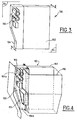
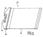
- This element 100 comprises a relatively flat and elongated positive temperature coefficient electrical harness 102 which makes it possible to heat by passing current therethrough and a housing 104 enclosing an electronic power card (comprising a support for components and integrated circuits) provided with of electrical connection terminals 106.
- an electronic power card comprising a support for components and integrated circuits
- the electronic power and control unit 104 is disposed in the extension of the beam 102 and has a thickness E equal to or slightly greater or even substantially greater than the thickness e of the beam 102.
- the thickness E the housing is about 20 mm while the thickness e of the beam is about 15 mm.
- the thickness E may be greater than the thickness e up to 20 to 30%.
- the lugs 106 protrude perpendicularly to the electronic control and power unit 104 and therefore to the beam 102. They are for example arranged at one end 102a of the housing 104 so as to allow at least a part of a ventilation apparatus, heating and / or air conditioning 110 occupy the place released by the perpendicular position of the housing, as shown in the figure 4 .
- pipes or air vents 115 may be arranged on the ventilation, heating and / or air conditioning apparatus, for example at the end 104b of the electronic control and power unit 104.
- the lugs 106 are arranged at the center of the power and control electronics 104 and symmetrically to obtain a positive temperature coefficient resistor 100 which can be mounted by one or the other of the lateral sides of the housing. Ventilation, heating and / or air conditioning apparatus 110.
- the lugs can be set back from the surface of the electronic control unit and control, in a countersink, so that they do not protrude from said housing.
- Lugs can be placed on both sides of the power and control electronics box.
- the housing can be slightly offset and connected to the beam by a suitable connector.
Landscapes
- Physics & Mathematics (AREA)
- Thermal Sciences (AREA)
- Engineering & Computer Science (AREA)
- Mechanical Engineering (AREA)
- Air-Conditioning For Vehicles (AREA)
- Devices For Blowing Cold Air, Devices For Blowing Warm Air, And Means For Preventing Water Condensation In Air Conditioning Units (AREA)
- Resistance Heating (AREA)
Abstract
Description
L'invention se rapporte à un élément de chauffage électrique pour appareil de ventilation, de chauffage et/ou de climatisation d'habitacle, notamment de véhicule automobile.The invention relates to an electric heating element for ventilation apparatus, heating and / or air conditioning cabin, including motor vehicle.
Actuellement, dans les appareils de ventilation, de chauffage et/ou de climatisation pour habitacle de véhicule automobile, il est courant d'utiliser, en complément du radiateur de chauffage, un élément de chauffage à faisceau de résistances piloté par une carte électronique disposée dans un boîtier de commande. Dans le cas d'une résistance électrique à coefficient de température positif (en abrégé : CTP) qui s'autorégule, le pilotage est du type électronique de puissance. Des éléments de chauffage à faisceau de résistances piloté par une carte électronique disposée dans un boîtier de commande sont notamment décrits dans
Le problème majeur rencontré pour implanter le faisceau avec son boîtier électronique est l'encombrement du boîtier renfermant l'électronique de commande dans l'espace alloué. Ce type de faisceau de résistances utilise en effet une puissance électrique élevée qui requiert l'utilisation d'un circuit imprimé volumineux à cause de la partie électronique, des composants et du support.The major problem encountered in implanting the beam with its electronic box is the size of the housing enclosing the control electronics in the allocated space. This type of resistor beam uses a high electrical power which requires the use of a large printed circuit because of the electronic part, the components and the support.
L'insertion de ce volume dans les espaces restreints alloués dans les véhicules automobiles est préjudiciable au bon dimensionnement de l'appareil de ventilation, de chauffage et/ou de climatisation pour garantir ses performances aérauliques et aérothermiques. De plus, il limite la possibilité de disposer les canalisations ou les bouches d'aération directement sur l'appareil de ventilation, de chauffage et/ou de climatisation, et peut ainsi conduire à une dissymétrie des conduits d'air internes ou des autres composants implantés dans l'appareil.The insertion of this volume in restricted spaces allocated in motor vehicles is detrimental to the proper sizing of the ventilation, heating and / or air conditioning to ensure its aeraulic and aerothermal performance. In addition, it limits the possibility of arranging the pipes or the air vents directly on the ventilation, heating and / or air conditioning apparatus, and can thus lead to an asymmetry of the internal air ducts or other components. implanted in the device.
Cette augmentation de l'encombrement provient plus explicitement du fait que dans ce type de montage, le boîtier s'étend perpendiculairement au plan du faisceau de résistances, comme illustré sur les
Pour résoudre ces problèmes, l'invention propose une nouvelle implantation de la partie électronique et par conséquent du boîtier la renfermant.To solve these problems, the invention proposes a new implantation of the electronic part and consequently of the housing enclosing it.
Plus précisément, l'invention a pour objet un élément de chauffage électrique pour appareil de ventilation, de chauffage et /ou de climatisation d'habitacle, notamment de véhicule automobile, selon la revendication 1.More specifically, the subject of the invention is an electric heating element for a ventilation, heating and / or air-conditioning apparatus for a passenger compartment, particularly a motor vehicle, according to claim 1.
Le parallélisme des plans du faisceau de résistances et de la carte électronique (correspondant au plan moyen du boîtier) s'entend au sens large, c'est-à-dire que les plans peuvent être considérés comme distincts ou confondus. Par ailleurs, le terme « sensiblement » signifie que les plans forment un angle de 0 à quelques degrés, par exemple 3 à 5 degrés, sans dépasser environ 10 degrés.The parallelism of the planes of the resistor beam and the electronic card (corresponding to the average plane of the housing) is understood in the broad sense, that is to say that the plans can be considered as distinct or confused. Moreover, the term "substantially" means that the planes form an angle of 0 to a few degrees, for example 3 to 5 degrees, without exceeding about 10 degrees.
L'invention se rapporte également à un appareil de ventilation, de chauffage et/ou de climatisation pour habitacle de véhicule automobile muni d'une telle résistance.The invention also relates to a ventilating, heating and / or air conditioning apparatus for a passenger compartment of a motor vehicle equipped with such a resistance.
D'autres caractéristiques, détails et avantages de l'invention ressortiront à la lecture de la description qui suit, faite en référence aux dessins annexés donnés à titre d'exemple et qui représentent respectivement :
- les
figures 1 et 2 , des vues schématiques en perspective d'un élément de chauffage de l'art antérieur, - la
figure 3 , une vue schématique en perspective d'un élément de chauffage, - la
figure 4 , une vue schématique en perspective d'un élément de chauffage monté dans un appareil de ventilation, de chauffage et/ou de climatisation, et - la
figure 5 , une vue schématique en perspective d'un élément de chauffage conforme à la présente invention.
- the
Figures 1 and 2 , schematic perspective views of a heating element of the prior art, - the
figure 3 , a schematic perspective view of a heating element, - the
figure 4 a schematic perspective view of a heating element mounted in a ventilation, heating and / or air conditioning apparatus, and - the
figure 5 , a schematic perspective view of a heating element according to the present invention.
Les
Sur la
Le boîtier électronique de puissance et de commande 104 est disposé dans le prolongement du faisceau 102 et présente une épaisseur E égale ou légèrement supérieure, voire sensiblement supérieure, à l'épaisseur e du faisceau 102. Dans l'exemple illustré, l'épaisseur E du boîtier est d'environ 20 mm alors que l'épaisseur e du faisceau est d'environ 15 mm. L'épaisseur E peut être supérieure à l'épaisseur e jusqu'à 20 à 30 %.The electronic power and
Les cosses 106 font saillie perpendiculairement au boîtier électronique de puissance et de commande 104 et donc au faisceau 102. Elles sont par exemple disposées à une extrémité 102a du boîtier 104 de façon à permettre à une partie au moins d'un appareil de ventilation, de chauffage et/ou de climatisation 110 d'occuper la place libérée par la position perpendiculaire du boîtier, comme représenté sur la
A la
Ainsi, cette disposition particulière du boîtier électronique de puissance et de commande par rapport au faisceau donne la possibilité :
- d'augmenter la section de passage de conduite d'air chaud en aval du radiateur de l'appareil de ventilation, de chauffage et/ou de climatisation,
- d'intégrer d'autres canaux latéraux internes dédiés à conduire de l'air chaud pour mettre au point les performances aérothermiques,
- de pouvoir positionner latéralement des conduits externes de diffusion d'air,
- de pouvoir implanter latéralement des bouches de diffusion d'air,
- de libérer un espace propice à implanter un système de liaison, une cinématique ou un organe de commande appartenant à l'appareil de ventilation, de chauffage et/ou de climatisation,
- d'améliorer ou de conserver la symétrie gauche-droite des conduits d'air ou des composants dans l'appareil de ventilation, de chauffage et/ou de climatisation,
- de réduire le volume pour la connexion électrique de la résistance sur le véhicule.
- to increase the section of passage of hot air duct downstream of the radiator of the ventilation, heating and / or air conditioning apparatus,
- to integrate other internal side channels dedicated to driving hot air to develop aerothermal performance,
- to be able to position laterally external air distribution ducts,
- to be able to laterally implant vents,
- to release a space suitable for implanting a connection system, a kinematic or a control member belonging to the ventilation, heating and / or air conditioning apparatus,
- improve or maintain the left-right symmetry of the air ducts or components in the ventilation, heating and / or air conditioning apparatus,
- to reduce the volume for the electrical connection of the resistor on the vehicle.
Il doit être bien entendu toutefois que la description détaillée, donnée uniquement à titre d'illustration de l'objet de l'Invention, ne constitue en aucune manière une limitation, les équivalents techniques étant également compris dans le champ de la présente invention.It should be understood, however, that the detailed description, given solely by way of illustration of the subject of the invention, does not in any way constitute a limitation, the technical equivalents also being included in the scope of the present invention.
Ainsi, les cosses peuvent être placée en retrait de la surface du boîtier électronique de puissance et de commande, dans un lamage, de sorte qu'elles ne font pas saillie dudit boîtier.Thus, the lugs can be set back from the surface of the electronic control unit and control, in a countersink, so that they do not protrude from said housing.
Les cosses peuvent être placées de part et d'autre du boîtier électronique de puissance et de commande.Lugs can be placed on both sides of the power and control electronics box.
Par ailleurs, le boîtier peut être légèrement déporté et relié au faisceau par une connectique adaptée.Furthermore, the housing can be slightly offset and connected to the beam by a suitable connector.
Claims (4)
- Heating element for a vehicle cabin ventilating, heating and air conditioning apparatus (110), in particular for a motor vehicle, including a planar (P1) electric resistance core (102) coupled to an electronic power and/or control box (104) equipped with electrical connection terminals (106) and integrating an electronic board, the electronic board and the box extending in a same plane (P2), the plane (P1) of the resistance core and the plane (P2) of the electronic board being substantially parallel,
characterised in that the terminals (106) are arranged perpendicularly to the plane (P1) containing the core (102), are centred and arranged symmetrically on the electronic power and control box (104). - Heating element according to claim 1, in which the electronic power and/or control box (104) has a thickness (E) substantially equal to or greater than the thickness (e) of the core.
- Heating element according to claim 1 or 2, in which the terminals (106) project from the electronic power and control box (104).
- Ventilating, heating and/or air conditioning apparatus (110) for a motor vehicle cabin, equipped with a heating element (100) according to any one of the previous claims.
Priority Applications (1)
| Application Number | Priority Date | Filing Date | Title |
|---|---|---|---|
| DE602004004455.5T DE602004004455T3 (en) | 2003-08-29 | 2004-07-08 | Electric heating element for ventilation, heating and / or air conditioning systems |
Applications Claiming Priority (2)
| Application Number | Priority Date | Filing Date | Title |
|---|---|---|---|
| FR0310327A FR2859349B1 (en) | 2003-08-29 | 2003-08-29 | ELECTRIC HEATING ELEMENT FOR VENTILATION, HEATING AND / OR AIR CONDITIONING APPARATUS |
| FR0310327 | 2003-08-29 |
Publications (3)
| Publication Number | Publication Date |
|---|---|
| EP1510381A1 EP1510381A1 (en) | 2005-03-02 |
| EP1510381B1 EP1510381B1 (en) | 2007-01-24 |
| EP1510381B2 true EP1510381B2 (en) | 2013-11-20 |
Family
ID=34089880
Family Applications (1)
| Application Number | Title | Priority Date | Filing Date |
|---|---|---|---|
| EP04016070.7A Expired - Lifetime EP1510381B2 (en) | 2003-08-29 | 2004-07-08 | Electrical heating element for ventilating, heating and/or air conditioning unit |
Country Status (5)
| Country | Link |
|---|---|
| EP (1) | EP1510381B2 (en) |
| AT (1) | ATE352443T1 (en) |
| DE (1) | DE602004004455T3 (en) |
| ES (1) | ES2280870T5 (en) |
| FR (1) | FR2859349B1 (en) |
Families Citing this family (2)
| Publication number | Priority date | Publication date | Assignee | Title |
|---|---|---|---|---|
| DE102007003549A1 (en) | 2007-01-24 | 2008-07-31 | Valeo Klimasysteme Gmbh | Air flow heating device with heating fleece |
| FR3079451A1 (en) * | 2018-03-29 | 2019-10-04 | Valeo Systemes Thermiques | ELECTRIC HEATING DEVICE AND INSTALLATION FOR HEATING AND / OR VENTILATION AND / OR AIR CONDITIONING THEREFOR |
Citations (2)
| Publication number | Priority date | Publication date | Assignee | Title |
|---|---|---|---|---|
| EP0840534A1 (en) † | 1996-11-01 | 1998-05-06 | E.G.O. ELEKTRO-GERÄTEBAU GmbH | Electric heating and control thereof |
| EP1338451A2 (en) † | 2002-02-26 | 2003-08-27 | Beru AG | Electrical air heater, in particular for a motor vehicle |
Family Cites Families (5)
| Publication number | Priority date | Publication date | Assignee | Title |
|---|---|---|---|---|
| DE19738318C5 (en) * | 1997-09-02 | 2014-10-30 | Behr Gmbh & Co. Kg | Electric heating device for a motor vehicle |
| DE19925757C5 (en) * | 1999-06-05 | 2011-02-10 | Behr France Rouffach S.A.S. | Heating device, in particular for a motor vehicle |
| ES2254568T3 (en) * | 2000-05-23 | 2006-06-16 | CATEM GMBH & CO.KG | ELECTRIC HEATING DEVICE, ESPECIALLY FOR THE APPLICATION OF CARS. |
| FR2827113B1 (en) * | 2001-07-09 | 2003-10-17 | Valeo Climatisation | ELECTRIC HEATING DEVICE, PARTICULARLY FOR A MOTOR VEHICLE HEATING SYSTEM |
| FR2826912B1 (en) * | 2001-07-09 | 2004-01-30 | Valeo Climatisation | AUTOMOTIVE COCKPIT HEATING SYSTEM |
-
2003
- 2003-08-29 FR FR0310327A patent/FR2859349B1/en not_active Expired - Fee Related
-
2004
- 2004-07-08 DE DE602004004455.5T patent/DE602004004455T3/en not_active Expired - Lifetime
- 2004-07-08 EP EP04016070.7A patent/EP1510381B2/en not_active Expired - Lifetime
- 2004-07-08 AT AT04016070T patent/ATE352443T1/en not_active IP Right Cessation
- 2004-07-08 ES ES04016070.7T patent/ES2280870T5/en not_active Expired - Lifetime
Patent Citations (2)
| Publication number | Priority date | Publication date | Assignee | Title |
|---|---|---|---|---|
| EP0840534A1 (en) † | 1996-11-01 | 1998-05-06 | E.G.O. ELEKTRO-GERÄTEBAU GmbH | Electric heating and control thereof |
| EP1338451A2 (en) † | 2002-02-26 | 2003-08-27 | Beru AG | Electrical air heater, in particular for a motor vehicle |
Also Published As
| Publication number | Publication date |
|---|---|
| ES2280870T5 (en) | 2014-03-12 |
| FR2859349A1 (en) | 2005-03-04 |
| EP1510381A1 (en) | 2005-03-02 |
| FR2859349B1 (en) | 2006-12-01 |
| ES2280870T3 (en) | 2007-09-16 |
| DE602004004455T2 (en) | 2007-11-15 |
| ATE352443T1 (en) | 2007-02-15 |
| DE602004004455D1 (en) | 2007-03-15 |
| EP1510381B1 (en) | 2007-01-24 |
| DE602004004455T3 (en) | 2014-07-17 |
Similar Documents
| Publication | Publication Date | Title |
|---|---|---|
| US6124570A (en) | Heating and air conditioning system for vehicles | |
| US9377244B2 (en) | Heat medium heating device and vehicle air conditioner including the same | |
| EP1998406B1 (en) | Electrical connection device between a power input source and an electric radiator, and method for manufacturing such a connection device | |
| US9937772B2 (en) | Heater | |
| WO2012020614A1 (en) | Battery temperature regulation system and battery temperature regulation unit | |
| CN111095665B (en) | Control module for air conditioning a battery | |
| FR2922817B1 (en) | DEVICE FOR ELECTRICALLY HEATING AN AIR FLOW CIRCULATING INSIDE A VENTILATION, HEATING AND / OR AIR CONDITIONING INSTALLATION OF A MOTOR VEHICLE | |
| EP2819863B1 (en) | Electric fluid heating device for a vehicle and corresponding heating and/or cooling device | |
| EP2516937B1 (en) | Electric heating device and corresponding heating appliance | |
| EP1986482B1 (en) | Additional device for electrically heating an air flow included in a ventilation, heating and/or air-conditioning installation of an automobile vehicle | |
| CN107206866B (en) | Electric heating device shell | |
| CN115087147A (en) | Electric heating device | |
| EP3017653A1 (en) | Fluid heating device for a motor vehicle and corresponding heating and/or air-conditioning apparatus | |
| US20050133490A1 (en) | PTC heating unit suitable for use in motor vehicles | |
| EP1510381B1 (en) | Electrical heating element for ventilating, heating and/or air conditioning unit | |
| FR2989034A1 (en) | ELECTRIC FLUID HEATING DEVICE FOR MOTOR VEHICLE AND METHOD FOR ASSEMBLING SAID HEATING DEVICE | |
| KR20020000648A (en) | Heating system for heating the passenger compartment of a motor vehicle | |
| JP2005218171A (en) | Power supply method from battery to load, power supply control device, and automobile | |
| FR3126480A1 (en) | ELECTRIC RADIATOR OF A VENTILATION, HEATING, AND/OR AIR CONDITIONING INSTALLATION OF A MOTOR VEHICLE. | |
| WO2020065165A1 (en) | Electric radiator of a ventilation, heating and/or air-conditioning system of a motor vehicle | |
| EP3437158B1 (en) | Electrical connection device, heating device and ventilation, heating and/or air conditioning unit | |
| KR102540468B1 (en) | PTC heater of dual type | |
| EP4078042B1 (en) | Fluid-heating device, in particular intended for a vehicle | |
| FR2954470A1 (en) | Electric heating device for use in air-conditioning and/or heating appliance for motor vehicle to heat different zones of vehicle cockpit, has openings arranged on side of heating block opposite to side carrying electric supply circuit | |
| WO2023057214A1 (en) | Electric heating device and corresponding heating, ventilation and/or air-conditioning installation |
Legal Events
| Date | Code | Title | Description |
|---|---|---|---|
| PUAI | Public reference made under article 153(3) epc to a published international application that has entered the european phase |
Free format text: ORIGINAL CODE: 0009012 |
|
| AK | Designated contracting states |
Kind code of ref document: A1 Designated state(s): AT BE BG CH CY CZ DE DK EE ES FI FR GB GR HU IE IT LI LU MC NL PL PT RO SE SI SK TR |
|
| AX | Request for extension of the european patent |
Extension state: AL HR LT LV MK |
|
| 17P | Request for examination filed |
Effective date: 20050805 |
|
| RAP1 | Party data changed (applicant data changed or rights of an application transferred) |
Owner name: VALEO SYSTEMES THERMIQUES |
|
| AKX | Designation fees paid |
Designated state(s): AT BE BG CH CY CZ DE DK EE ES FI FR GB GR HU IE IT LI LU MC NL PL PT RO SE SI SK TR |
|
| GRAP | Despatch of communication of intention to grant a patent |
Free format text: ORIGINAL CODE: EPIDOSNIGR1 |
|
| GRAS | Grant fee paid |
Free format text: ORIGINAL CODE: EPIDOSNIGR3 |
|
| GRAA | (expected) grant |
Free format text: ORIGINAL CODE: 0009210 |
|
| AK | Designated contracting states |
Kind code of ref document: B1 Designated state(s): AT BE BG CH CY CZ DE DK EE ES FI FR GB GR HU IE IT LI LU MC NL PL PT RO SE SI SK TR |
|
| PG25 | Lapsed in a contracting state [announced via postgrant information from national office to epo] |
Ref country code: SI Free format text: LAPSE BECAUSE OF FAILURE TO SUBMIT A TRANSLATION OF THE DESCRIPTION OR TO PAY THE FEE WITHIN THE PRESCRIBED TIME-LIMIT Effective date: 20070124 Ref country code: PL Free format text: LAPSE BECAUSE OF FAILURE TO SUBMIT A TRANSLATION OF THE DESCRIPTION OR TO PAY THE FEE WITHIN THE PRESCRIBED TIME-LIMIT Effective date: 20070124 Ref country code: NL Free format text: LAPSE BECAUSE OF FAILURE TO SUBMIT A TRANSLATION OF THE DESCRIPTION OR TO PAY THE FEE WITHIN THE PRESCRIBED TIME-LIMIT Effective date: 20070124 Ref country code: IE Free format text: LAPSE BECAUSE OF FAILURE TO SUBMIT A TRANSLATION OF THE DESCRIPTION OR TO PAY THE FEE WITHIN THE PRESCRIBED TIME-LIMIT Effective date: 20070124 Ref country code: DK Free format text: LAPSE BECAUSE OF FAILURE TO SUBMIT A TRANSLATION OF THE DESCRIPTION OR TO PAY THE FEE WITHIN THE PRESCRIBED TIME-LIMIT Effective date: 20070124 Ref country code: AT Free format text: LAPSE BECAUSE OF FAILURE TO SUBMIT A TRANSLATION OF THE DESCRIPTION OR TO PAY THE FEE WITHIN THE PRESCRIBED TIME-LIMIT Effective date: 20070124 Ref country code: FI Free format text: LAPSE BECAUSE OF FAILURE TO SUBMIT A TRANSLATION OF THE DESCRIPTION OR TO PAY THE FEE WITHIN THE PRESCRIBED TIME-LIMIT Effective date: 20070124 |
|
| REG | Reference to a national code |
Ref country code: GB Ref legal event code: FG4D Free format text: NOT ENGLISH |
|
| GRAL | Information related to payment of fee for publishing/printing deleted |
Free format text: ORIGINAL CODE: EPIDOSDIGR3 |
|
| GRAS | Grant fee paid |
Free format text: ORIGINAL CODE: EPIDOSNIGR3 |
|
| REG | Reference to a national code |
Ref country code: CH Ref legal event code: EP |
|
| REG | Reference to a national code |
Ref country code: IE Ref legal event code: FG4D Free format text: LANGUAGE OF EP DOCUMENT: FRENCH |
|
| REF | Corresponds to: |
Ref document number: 602004004455 Country of ref document: DE Date of ref document: 20070315 Kind code of ref document: P |
|
| PG25 | Lapsed in a contracting state [announced via postgrant information from national office to epo] |
Ref country code: SE Free format text: LAPSE BECAUSE OF FAILURE TO SUBMIT A TRANSLATION OF THE DESCRIPTION OR TO PAY THE FEE WITHIN THE PRESCRIBED TIME-LIMIT Effective date: 20070424 |
|
| PG25 | Lapsed in a contracting state [announced via postgrant information from national office to epo] |
Ref country code: BG Free format text: LAPSE BECAUSE OF FAILURE TO SUBMIT A TRANSLATION OF THE DESCRIPTION OR TO PAY THE FEE WITHIN THE PRESCRIBED TIME-LIMIT Effective date: 20070425 |
|
| PG25 | Lapsed in a contracting state [announced via postgrant information from national office to epo] |
Ref country code: PT Free format text: LAPSE BECAUSE OF FAILURE TO SUBMIT A TRANSLATION OF THE DESCRIPTION OR TO PAY THE FEE WITHIN THE PRESCRIBED TIME-LIMIT Effective date: 20070625 |
|
| NLV1 | Nl: lapsed or annulled due to failure to fulfill the requirements of art. 29p and 29m of the patents act | ||
| GBV | Gb: ep patent (uk) treated as always having been void in accordance with gb section 77(7)/1977 [no translation filed] |
Effective date: 20070124 |
|
| REG | Reference to a national code |
Ref country code: IE Ref legal event code: FD4D |
|
| REG | Reference to a national code |
Ref country code: ES Ref legal event code: FG2A Ref document number: 2280870 Country of ref document: ES Kind code of ref document: T3 |
|
| PLBI | Opposition filed |
Free format text: ORIGINAL CODE: 0009260 |
|
| PLBI | Opposition filed |
Free format text: ORIGINAL CODE: 0009260 |
|
| PG25 | Lapsed in a contracting state [announced via postgrant information from national office to epo] |
Ref country code: GB Free format text: LAPSE BECAUSE OF FAILURE TO SUBMIT A TRANSLATION OF THE DESCRIPTION OR TO PAY THE FEE WITHIN THE PRESCRIBED TIME-LIMIT Effective date: 20070124 Ref country code: SK Free format text: LAPSE BECAUSE OF FAILURE TO SUBMIT A TRANSLATION OF THE DESCRIPTION OR TO PAY THE FEE WITHIN THE PRESCRIBED TIME-LIMIT Effective date: 20070124 |
|
| PLAX | Notice of opposition and request to file observation + time limit sent |
Free format text: ORIGINAL CODE: EPIDOSNOBS2 |
|
| 26 | Opposition filed |
Opponent name: BERU AG Effective date: 20071022 |
|
| 26 | Opposition filed |
Opponent name: BERU AG Effective date: 20071022 Opponent name: BEHR GMBH & CO. KG Effective date: 20071023 |
|
| PG25 | Lapsed in a contracting state [announced via postgrant information from national office to epo] |
Ref country code: RO Free format text: LAPSE BECAUSE OF FAILURE TO SUBMIT A TRANSLATION OF THE DESCRIPTION OR TO PAY THE FEE WITHIN THE PRESCRIBED TIME-LIMIT Effective date: 20070124 |
|
| BERE | Be: lapsed |
Owner name: VALEO SYSTEMES THERMIQUES Effective date: 20070731 |
|
| PLAF | Information modified related to communication of a notice of opposition and request to file observations + time limit |
Free format text: ORIGINAL CODE: EPIDOSCOBS2 |
|
| PG25 | Lapsed in a contracting state [announced via postgrant information from national office to epo] |
Ref country code: GR Free format text: LAPSE BECAUSE OF FAILURE TO SUBMIT A TRANSLATION OF THE DESCRIPTION OR TO PAY THE FEE WITHIN THE PRESCRIBED TIME-LIMIT Effective date: 20070425 Ref country code: MC Free format text: LAPSE BECAUSE OF NON-PAYMENT OF DUE FEES Effective date: 20070731 |
|
| PLAF | Information modified related to communication of a notice of opposition and request to file observations + time limit |
Free format text: ORIGINAL CODE: EPIDOSCOBS2 |
|
| PLAB | Opposition data, opponent's data or that of the opponent's representative modified |
Free format text: ORIGINAL CODE: 0009299OPPO |
|
| PLAS | Information related to reply of patent proprietor to notice(s) of opposition deleted |
Free format text: ORIGINAL CODE: EPIDOSDOBS3 |
|
| PLBB | Reply of patent proprietor to notice(s) of opposition received |
Free format text: ORIGINAL CODE: EPIDOSNOBS3 |
|
| PG25 | Lapsed in a contracting state [announced via postgrant information from national office to epo] |
Ref country code: BE Free format text: LAPSE BECAUSE OF NON-PAYMENT OF DUE FEES Effective date: 20070731 |
|
| PLBB | Reply of patent proprietor to notice(s) of opposition received |
Free format text: ORIGINAL CODE: EPIDOSNOBS3 |
|
| PG25 | Lapsed in a contracting state [announced via postgrant information from national office to epo] |
Ref country code: EE Free format text: LAPSE BECAUSE OF FAILURE TO SUBMIT A TRANSLATION OF THE DESCRIPTION OR TO PAY THE FEE WITHIN THE PRESCRIBED TIME-LIMIT Effective date: 20070124 |
|
| REG | Reference to a national code |
Ref country code: CH Ref legal event code: PL |
|
| PG25 | Lapsed in a contracting state [announced via postgrant information from national office to epo] |
Ref country code: CH Free format text: LAPSE BECAUSE OF NON-PAYMENT OF DUE FEES Effective date: 20080731 Ref country code: LI Free format text: LAPSE BECAUSE OF NON-PAYMENT OF DUE FEES Effective date: 20080731 |
|
| PG25 | Lapsed in a contracting state [announced via postgrant information from national office to epo] |
Ref country code: CY Free format text: LAPSE BECAUSE OF FAILURE TO SUBMIT A TRANSLATION OF THE DESCRIPTION OR TO PAY THE FEE WITHIN THE PRESCRIBED TIME-LIMIT Effective date: 20070124 |
|
| PG25 | Lapsed in a contracting state [announced via postgrant information from national office to epo] |
Ref country code: LU Free format text: LAPSE BECAUSE OF NON-PAYMENT OF DUE FEES Effective date: 20070708 |
|
| PG25 | Lapsed in a contracting state [announced via postgrant information from national office to epo] |
Ref country code: TR Free format text: LAPSE BECAUSE OF FAILURE TO SUBMIT A TRANSLATION OF THE DESCRIPTION OR TO PAY THE FEE WITHIN THE PRESCRIBED TIME-LIMIT Effective date: 20070124 Ref country code: HU Free format text: LAPSE BECAUSE OF FAILURE TO SUBMIT A TRANSLATION OF THE DESCRIPTION OR TO PAY THE FEE WITHIN THE PRESCRIBED TIME-LIMIT Effective date: 20070725 |
|
| PLAB | Opposition data, opponent's data or that of the opponent's representative modified |
Free format text: ORIGINAL CODE: 0009299OPPO |
|
| R26 | Opposition filed (corrected) |
Opponent name: BERU AG Effective date: 20071022 Opponent name: BEHR GMBH & CO. KG Effective date: 20071023 |
|
| PLAB | Opposition data, opponent's data or that of the opponent's representative modified |
Free format text: ORIGINAL CODE: 0009299OPPO |
|
| R26 | Opposition filed (corrected) |
Opponent name: BORGWARNER BERU SYSTEMS GMBH Effective date: 20071022 Opponent name: BEHR GMBH & CO. KG Effective date: 20071023 |
|
| APAH | Appeal reference modified |
Free format text: ORIGINAL CODE: EPIDOSCREFNO |
|
| APBM | Appeal reference recorded |
Free format text: ORIGINAL CODE: EPIDOSNREFNO |
|
| APBP | Date of receipt of notice of appeal recorded |
Free format text: ORIGINAL CODE: EPIDOSNNOA2O |
|
| APBM | Appeal reference recorded |
Free format text: ORIGINAL CODE: EPIDOSNREFNO |
|
| APBP | Date of receipt of notice of appeal recorded |
Free format text: ORIGINAL CODE: EPIDOSNNOA2O |
|
| APBQ | Date of receipt of statement of grounds of appeal recorded |
Free format text: ORIGINAL CODE: EPIDOSNNOA3O |
|
| APBQ | Date of receipt of statement of grounds of appeal recorded |
Free format text: ORIGINAL CODE: EPIDOSNNOA3O |
|
| PLAB | Opposition data, opponent's data or that of the opponent's representative modified |
Free format text: ORIGINAL CODE: 0009299OPPO |
|
| R26 | Opposition filed (corrected) |
Opponent name: BEHR GMBH & CO. KG Effective date: 20071023 Opponent name: BORGWARNER BERU SYSTEMS GMBH Effective date: 20071022 |
|
| APBU | Appeal procedure closed |
Free format text: ORIGINAL CODE: EPIDOSNNOA9O |
|
| PUAH | Patent maintained in amended form |
Free format text: ORIGINAL CODE: 0009272 |
|
| STAA | Information on the status of an ep patent application or granted ep patent |
Free format text: STATUS: PATENT MAINTAINED AS AMENDED |
|
| 27A | Patent maintained in amended form |
Effective date: 20131120 |
|
| AK | Designated contracting states |
Kind code of ref document: B2 Designated state(s): AT BE BG CH CY CZ DE DK EE ES FI FR GB GR HU IE IT LI LU MC NL PL PT RO SE SI SK TR |
|
| REG | Reference to a national code |
Ref country code: DE Ref legal event code: R102 Ref document number: 602004004455 Country of ref document: DE |
|
| REG | Reference to a national code |
Ref country code: DE Ref legal event code: R102 Ref document number: 602004004455 Country of ref document: DE Effective date: 20131120 |
|
| REG | Reference to a national code |
Ref country code: ES Ref legal event code: DC2A Ref document number: 2280870 Country of ref document: ES Kind code of ref document: T5 Effective date: 20140312 |
|
| REG | Reference to a national code |
Ref country code: DE Ref legal event code: R082 Ref document number: 602004004455 Country of ref document: DE Representative=s name: MAIWALD PATENTANWALTS GMBH, DE Ref country code: DE Ref legal event code: R082 Ref document number: 602004004455 Country of ref document: DE Representative=s name: MAIWALD PATENTANWALTS- UND RECHTSANWALTSGESELL, DE |
|
| REG | Reference to a national code |
Ref country code: FR Ref legal event code: PLFP Year of fee payment: 13 |
|
| REG | Reference to a national code |
Ref country code: FR Ref legal event code: PLFP Year of fee payment: 14 |
|
| REG | Reference to a national code |
Ref country code: DE Ref legal event code: R082 Ref document number: 602004004455 Country of ref document: DE Representative=s name: MAIWALD GMBH, DE Ref country code: DE Ref legal event code: R082 Ref document number: 602004004455 Country of ref document: DE Representative=s name: MAIWALD PATENTANWALTS- UND RECHTSANWALTSGESELL, DE |
|
| REG | Reference to a national code |
Ref country code: FR Ref legal event code: PLFP Year of fee payment: 15 |
|
| REG | Reference to a national code |
Ref country code: ES Ref legal event code: FD2A Effective date: 20190917 |
|
| PG25 | Lapsed in a contracting state [announced via postgrant information from national office to epo] |
Ref country code: ES Free format text: LAPSE BECAUSE OF NON-PAYMENT OF DUE FEES Effective date: 20180709 |
|
| PGFP | Annual fee paid to national office [announced via postgrant information from national office to epo] |
Ref country code: IT Payment date: 20200713 Year of fee payment: 17 |
|
| PGFP | Annual fee paid to national office [announced via postgrant information from national office to epo] |
Ref country code: CZ Payment date: 20210622 Year of fee payment: 18 |
|
| PG25 | Lapsed in a contracting state [announced via postgrant information from national office to epo] |
Ref country code: IT Free format text: LAPSE BECAUSE OF NON-PAYMENT OF DUE FEES Effective date: 20210708 |
|
| PG25 | Lapsed in a contracting state [announced via postgrant information from national office to epo] |
Ref country code: CZ Free format text: LAPSE BECAUSE OF NON-PAYMENT OF DUE FEES Effective date: 20220708 |
|
| P01 | Opt-out of the competence of the unified patent court (upc) registered |
Effective date: 20230528 |
|
| PGFP | Annual fee paid to national office [announced via postgrant information from national office to epo] |
Ref country code: FR Payment date: 20230727 Year of fee payment: 20 Ref country code: DE Payment date: 20230712 Year of fee payment: 20 |