BACKGROUND OF THE INVENTION
1. Field of the Invention
The present invention relates to an ink-jet head for
printing by ejecting ink onto a print medium, and to an ink-jet
printer having the ink-jet head.
2. Description of Related Art
In an ink-jet printer, an ink-jet head distributes ink,
which is supplied from an ink tank, to pressure chambers. The
ink-jet head selectively applies pressure to each pressure
chamber to eject ink through a nozzle. As a means for
selectively applying pressure to the pressure chambers, an
actuator unit may be used in which ceramic piezoelectric sheets
are laminated.
As an example, an ink-jet head of that kind is known having
one actuator unit in which continuous flat piezoelectric sheets
extending over a plurality of pressure chambers are laminated
and at least one of the piezoelectric sheets is sandwiched by a
common electrode common to many pressure chambers and being kept
at the ground potential, and many individual electrodes, i.e.,
driving electrodes, disposed at positions corresponding to the
respective pressure chambers (refer to US Pat. No.5,402,159).
The part of piezoelectric sheet being sandwiched by the
individual and common electrodes and polarized in its thickness
is expanded or contracted in its thickness direction as an
active layer, by the so-called longitudinal piezoelectric
effect, when a individual electrode on one face of the sheet is
set at a different potential from that of the common electrode
on the other face. The volume of the corresponding pressure
chamber thereby changes, so ink can be ejected toward a print
medium through a nozzle communicating with the pressure chamber.
In such an ink-jet head, to ensure good ink ejection
performance, the actuator unit must be accurately positioned to
a passage unit so that the individual electrodes must be at
predetermined positions corresponding to the respective pressure
chambers in a plan view.
In many cases, such an ink-jet head as described above is
manufactured in the following manner because of various
restrictions on manufacture. That is, the passage unit in which
ink passages including pressure chambers have been formed is
manufactured separately from the actuator unit. The passage
unit is then bonded with an adhesive to the actuator unit so
that the pressure chambers be close to the actuator unit. This
bonding process is done as a mark formed on the passage unit is
made to coincide with a mark formed on the actuator unit.
In general, however, the piezoelectric sheets of the
actuator unit are manufactured through a sintering process while
the passage unit is laminated with metallic sheets. Therefore,
the larger the size of the piezoelectric sheets is, the lower
the positional accuracy of the electrodes is. Thus, the longer
the head is, the more the positioning process is difficult
between the pressure chambers in the passage unit and the
individual electrodes in the actuator unit. As a result, the
manufacture yield of heads may be lowered.
On the other hand, the actuator unit is an expensive minute
component and it is very brittle because it is made of ceramic.
Particularly in the actuator unit having a polygonal shape, its
corners are very easy to be broken off. The break loss is a
cause of an increase in manufacture cost. Besides, very
delicate handling of the actuator unit is required such that any
corner must not collide against another component. This makes
it difficult to assemble the ink-jet head.
SUMMARY OF THE INVENTION
An object of the present invention is to provide an ink-jet
head in which an actuator unit has been accurately positioned to
a passage unit.
Another object of the present invention is to provide an
ink-jet head in which an actuator unit is hard to be broken.
According to one aspect of the present invention provided is
an ink-jet head comprising a passage unit including a plurality
of pressure chambers each having one end connected with a nozzle
and the other end to be connected with an ink supply source.
The plurality of pressure chambers are arranged along a plane to
neighbor each other. The ink-jet head further comprises
actuator units fixed to a surface of the passage unit for
changing the volume of each pressure chamber. Each actuator
unit includes pressure generation portions respectively
corresponding to pressure chambers. Each actuator unit is
formed to extend over the pressure chambers. The actuator units
are arranged along the longitudinal direction of the passage
unit so that each neighboring actuator units partially overlap
each other in the lateral direction of the passage unit. Each
actuator unit comprises a basic region where a large number of
pressure generation portions are formed in a matrix, and an
additional region neighboring the basic region in the lateral
direction of the passage unit. In the additional region,
pressure generation portions are formed to correspond to a gap
portion between the pressure generation portions in the basic
region of the actuator unit and the pressure generation portions
in the basic region of another actuator unit neighboring that
actuator unit. The present invention provides also an ink-jet
printer having the ink-jet head.
In this construction, each of the actuator units can be
positioned to the passage unit independently of each other.
Therefore, even in case of a long head, the increase in
positional shift between electrode and pressure chamber of each
actuator unit can be suppressed. Thus, both can accurately be
positioned to each other. As a result, good ink ejection
performance can be obtained and the manufacture yield of heads
is improved. In addition, since the pressure generation
portions in the additional region provided in an actuator unit
correspond to the gap portion between them and the pressure
generation portions in the basic region of a neighboring
actuator unit, the number of pressure generation portions can
not be made small in the vicinity of the seam portion between
the actuator unit and the neighboring actuator unit. Therefore,
a head can be obtained in which there is substantially no
variation in the number of pressure generation portions along
the longitudinal direction of the passage unit.
According to another aspect of the present invention
provided is an ink-jet head comprising a passage unit including
pressure chambers each communicating with a nozzle for ejecting
ink. The plurality of pressure chambers are arranged along a
plane to neighbor each other. The ink-jet head further
comprises an actuator unit fixed to a surface of the passage
unit for changing the volume of each pressure chamber. The
actuator unit is formed to extend along the pressure chambers.
The actuator unit includes pressure generation portions
corresponding to the respective pressure chambers. The actuator
unit has its profile with five or more straight portions. Each
straight portion is connected with a neighboring straight
portion at the right angle or an obtuse angle.
In this feature, by making any corner of the actuator unit
into the right angle or an obtuse angle, the actuator unit is
hard to be broken upon manufacturing the ink-jet head.
According to further another aspect of the present invention
provided is an ink-jet head comprising a passage unit including
a plurality of pressure chambers each communicating with a
nozzle for ejecting ink. The plurality of pressure chambers are
arranged along a plane to neighbor each other. The ink-jet head
further comprises a plurality of actuator units arranged along
the longitudinal direction of the passage unit and fixed to a
surface of the passage unit for changing the volume of each of
the pressure chambers. Each of the actuator units includes a
plurality of pressure generation portions respectively
corresponding to pressure chambers Each of the actuator units
is formed to extend over the pressure chambers.
In this construction, each of the actuator units can be
positioned to the passage unit independently of each other.
Therefore, even in case of a long head, the increase in
positional shift between electrode and pressure chamber of each
actuator unit can be suppressed. Thus, both can accurately be
positioned to each other. As a result, good ink ejection
performance can be obtained and the manufacture yield of heads
is improved.
BRIEF DESCRIPTION OF THE DRAWINGS
Other and further objects, features and advantages of the
invention will appear more fully from the following description
taken in connection with the accompanying drawings in which:
DESCRIPTION OF THE PREFERRED EMBODIMENTS
First, an ink-jet head as a reference for understanding ink-jet
heads according to embodiments of the present invention will
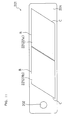
be described with reference to FIGS. 1 to 10. FIG. 1 is a
general view of an ink-jet printer including ink-jet heads
according to a first embodiment of the present invention. The
ink-jet printer 101 as illustrated in FIG. 1 is a color ink-jet
printer having four ink-jet heads 1. In this printer 101, a
paper feed unit 111 and a paper discharge unit 112 are disposed
in left and right portions of FIG. 1, respectively.
In the printer 101, a paper transfer path is provided
extending from the paper feed unit 111 to the paper discharge
unit 112. A pair of feed rollers 105a and 105b is disposed
immediately downstream of the paper feed unit 111 for pinching
and putting forward a paper as an image record medium. By the
pair of feed rollers 105a and 105b, the paper is transferred
from the left to the right in FIG. 1. In the middle of the
paper transfer path, two belt rollers 106 and 107 and an endless
transfer belt 108 are disposed. The transfer belt 108 is wound
on the belt rollers 106 and 107 to extend between them. The
outer face, i.e., the transfer face, of the transfer belt 108
has been treated with silicone. Thus, a paper fed through the
pair of feed rollers 105a and 105b can be held on the transfer
face of the transfer belt 108 by the adhesion of the face. In
this state, the paper is transferred downstream (rightward) by
driving one belt roller 106 to rotate clockwise in FIG. 1 (the
direction indicated by an arrow 104).
Pressing members 109a and 109b are disposed at positions for
feeding a paper onto the belt roller 106 and taking out the
paper from the belt roller 106, respectively. Either of the
pressing members 109a and 109b is for pressing the paper onto
the transfer face of the transfer belt 108 so as to prevent the
paper from separating from the transfer face of the transfer
belt 108. Thus, the paper surely adheres to the transfer face.
A peeling device 110 is provided immediately downstream of
the transfer belt 108 along the paper transfer path. The
peeling device 110 peels off the paper, which has adhered to the
transfer face of the transfer belt 108, from the transfer face
to transfer the paper toward the rightward paper discharge unit
112.
Each of the four ink-jet heads 1 has, at its lower end, a
head main body 1a. Each head main body 1a has a rectangular
section. The head main bodies 1a are arranged close to each
other with the longitudinal axis of each head main body 1a being
perpendicular to the paper transfer direction (perpendicular to
FIG. 1). That is, this printer 101 is a line type. The bottom
of each of the four head main bodies 1a faces the paper transfer
path. In the bottom of each head main body 1a, a number of
nozzles are provided each having a small-diameter ink ejection
port. The four head main bodies 1a eject ink of magenta,
yellow, cyan, and black, respectively.
The head main bodies 1a are disposed such that a narrow
clearance is formed between the lower face of each head main
body 1a and the transfer face of the transfer belt 108. The
paper transfer path is formed within the clearance. In this
construction, while a paper, which is being transferred by the
transfer belt 108, passes immediately below the four head main
bodies 1a in order, the respective color inks are ejected
through the corresponding nozzles toward the upper face, i.e.,
the print face, of the paper to form a desired color image on
the paper.
The ink-jet printer 101 is provided with a maintenance unit
117 for automatically carrying out maintenance of the ink-jet
heads 1. The maintenance unit 117 includes four caps 116 for
covering the lower faces of the four head main bodies 1a, and a
not-illustrated purge system.
The maintenance unit 117 is at a position immediately below
the paper feed unit 111 (withdrawal position) while the ink-jet
printer 101 operates to print. When a predetermined condition
is satisfied after finishing the printing operation (for
example, when a state in which no printing operation is
performed continues for a predetermined time period or when the
printer 101 is powered off), the maintenance unit 117 moves to a
position immediately below the four head main bodies 1a (cap
position), where the maintenance unit 117 covers the lower faces
of the head main bodies 1a with the respective caps 116 to
prevent ink in the nozzles of the head main bodies 1a from being
dried.
The belt rollers 106 and 107 and the transfer belt 108 are
supported by a chassis 113. The chassis 113 is put on a
cylindrical member 115 disposed under the chassis 113. The
cylindrical member 115 is rotatable around a shaft 114 provided
at a position deviating from the center of the cylindrical
member 115. Thus, by rotating the shaft 114, the level of the
uppermost portion of the cylindrical member 115 can be changed
to move up or down the chassis 113 accordingly. When the
maintenance unit 117 is moved from the withdrawal position to
the cap position, the cylindrical member 115 must have been
rotated at a predetermined angle in advance so as to move down
the transfer belt 108 and the belt rollers 106 and 107 by a
pertinent distance from the position illustrated in FIG. 1. A
space for the movement of the maintenance unit 117 is thereby
ensured.
In the region surrounded by the transfer belt 108, a nearly
rectangular parallelepiped guide 121 (having its width
substantially equal to that of the transfer belt 108) is
disposed at an opposite position to the ink-jet heads 1. The
guide 121 is in contact with the lower face of the upper part of
the transfer belt 108 to support the upper part of the transfer
belt 108 from the inside.
Next, the construction of each ink-jet head 1 according to
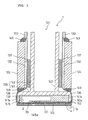
this embodiment will be described in more detail. FIG. 2 is a
perspective view of the ink-jet head 1. FIG. 3 is a sectional
view taken along line III-III in FIG. 2. Referring to FIGS. 2
and 3, the ink-jet head 1 according to this embodiment includes
a head main body 1a having a rectangular shape in a plan view
and extending in one direction (main scanning direction), and a
base portion 131 for supporting the head main body 1a. The base
portion 131 supporting the head main body 1a further supports
thereon driver ICs 132 for supplying driving signals to
individual electrodes 35a and 35b (see FIG. 6 and FIG. 10), and
substrates 133.
Referring to FIG. 2, the base portion 131 is made up of a
base block 138 partially bonded to the upper face of the head
main body 1a to support the head main body 1a, and a holder 139
bonded to the upper face of the base block 138 to support the
base block 138. The base block 138 is a nearly rectangular
parallelepiped member having substantially the same length of
the head main body 1a. The base block 138 made of metal
material such as stainless steel has a function as a light
structure for reinforcing the holder 139. The holder 139 is
made up of a holder main body 141 disposed near the head main
body 1a, and a pair of holder support portions 142 each
extending on the opposite side of the holder main body 141 to
the head main body 1a. Each holder support portion 142 is as a
flat member. These holder support portions 142 extend along the
longitudinal direction of the holder main body 141 and are
disposed in parallel with each other at a predetermined
interval.
Skirt portions 141a in a pair, protruding downward, are
provided in both end portions of the holder main body 141a in a
sub scanning direction (perpendicular to the main scanning
direction). Either skirt portion 141a is formed through the
length of the holder main body 141. As a result, in the lower
portion of the holder main body 141, a nearly rectangular
parallelepiped groove 141b is defined by the pair of skirt
portions 141a. The base block 138 is received in the groove
141b. The upper surface of the base block 138 is bonded to the
bottom of the groove 141b of the holder main body 141 with an
adhesive. The thickness of the base block 138 is somewhat
larger than the depth of the groove 141b of the holder main body
141. As a result, the lower end of the base block 138 protrudes
downward beyond the skirt portions 141a.
Within the base block 138, as a passage for ink to be
supplied to the head main body 1a, an ink reservoir 3 is formed
as a nearly rectangular parallelepiped space (hollow region)
extending along the longitudinal direction of the base block
138. In the lower face 145 of the base block 138, openings 3b
(see FIG. 4) are formed each communicating with the ink
reservoir 3. The ink reservoir 3 is connected through a not-illustrated
supply tube with a not-illustrated main ink tank
(ink supply source) within the printer main body. Thus, the ink
reservoir 3 is suitably supplied with ink from the main ink
tank.
In the lower face 145 of the base block 138, the vicinity of
each opening 3b protrudes downward from the surrounding portion.
The base block 138 is in contact with a passage unit 4 (see FIG.
3) of the head main body 1a at the only vicinity portion 145a of
each opening 3b of the lower face 145. Thus, the region of the
lower face 145 of the base block 138 other than the vicinity
portion 145a of each opening 3b is distant from the head main
body 1a. Actuator units 21 are disposed within the distance.
To the outer side face of each holder support portion 142 of
the holder 139, a driver IC 132 is fixed with an elastic member
137 such as a sponge being interposed between them. A heat sink
134 is disposed in close contact with the outer side face of the
driver IC 132. The heat sink 134 is made of a nearly
rectangular parallelepiped member for efficiently radiating heat
generated in the driver IC 132. A flexible printed circuit
(FPC) 136 as a power supply member is connected with the driver
IC 132. The FPC 136 connected with the driver IC 132 is bonded
to and electrically connected with the corresponding substrate
133 and the head main body 1a by soldering. The substrate 133
is disposed outside the FPC 136 above the driver IC 132 and the
heat sink 134. The upper face of the heat sink 134 is bonded to
the substrate 133 with a seal member 149. Also, the lower face
of the heat sink 134 is bonded to the FPC 136 with a seal member
149.
Between the lower face of each skirt portion 141a of the
holder main body 141 and the upper face of the passage unit 4, a
seal member 150 is disposed to sandwich the FPC 136. The FPC
136 is fixed by the seal member 150 to the passage unit 4 and
the holder main body 141. Therefore, even if the head main body
1a is elongated, the head main body 1a can be prevented from
being bent, the interconnecting portion between each actuator
unit and the FPC 136 can be prevented from receiving stress, and
the FPC 136 can surely be held.
Referring to FIG. 2, in the vicinity of each lower corner of
the ink-jet head 1 along the main scanning direction, six
protruding portions 30a are disposed at regular intervals along
the corresponding side wall of the ink-jet head 1. These
protruding portions 30a are provided at both ends in the sub
scanning direction of a nozzle plate 30 in the lowermost layer
of the head main body 1a (see FIGS. 7A and 7B). The nozzle
plate 30 is bent by about 90 degrees along the boundary line
between each protruding portion 30a and the other portion. The
protruding portions 30a are provided at positions corresponding
to the vicinities of both ends of various papers to be used for
printing. Each bent portion of the nozzle plate 30 has a shape
not right-angled but rounded. This makes it hard to bring about
clogging of a paper, i.e., jamming, which may occur because the
leading edge of the paper, which has been transferred to
approach the head 1, is stopped by the side face of the head 1.
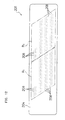
FIG. 4 is a schematic plan view of the head main body 1a.
In FIG. 4, an ink reservoir 3 formed in the base block 138 is
imaginarily illustrated with a broken line. Referring to FIG.
4, the head main body 1a has a rectangular shape in the plan
view extending in one direction (main scanning direction). The
head main body 1a includes a passage unit 4 in which a large
number of pressure chambers 10 and a large number of ink
ejection ports 8 at the front ends of nozzles (as for both, see
FIGS. 5, 6, and 7), as described later. Trapezoidal actuator
units 21 arranged in two lines in a zigzag manner are bonded
onto the upper face of the passage unit 4. Each actuator unit
21 is disposed such that its parallel opposed sides (upper and
lower sides) extend along the longitudinal direction of the
passage unit 4. The oblique sides of each neighboring actuator
units 21 overlap each other in the lateral direction of the
passage unit 4.
The lower face of the passage unit 4 corresponding to the
bonded region of each actuator unit 4 is made into an ink
ejection region. In the surface of each ink ejection region, a
large number of ink ejection ports 8 are arranged in a matrix,
as described later. In the base block 138 disposed above the
passage unit 4, an ink reservoir 3 is formed along the
longitudinal direction of the base block 138. The ink reservoir
3 communicates with an ink tank (not illustrated) through an
opening 3a provided at one end of the ink reservoir 3, so that
the ink reservoir 3 is always filled up with ink. In the ink
reservoir 3, pairs of openings 3b are provided in regions where
no actuator unit 21 is present, so as to be arranged in a zigzag
manner along the longitudinal direction of the ink reservoir 3.
FIG. 5 is an enlarged view of the region enclosed with an
alternate long and short dash line in FIG. 4. Referring to
FIGS. 4 and 5, the ink reservoir 3 communicates through each
opening 3b with a manifold channel 5 disposed under the opening
3b. Each opening 3b is provided with a filter (not illustrated)
for catching dust and dirt contained in ink. The front end
portion of each manifold channel 5 branches into two sub-manifold
channels 5a. Below a single one of the actuator unit
21, two sub-manifold channels 5a extend from each of the two
openings 3b on both sides of the actuator unit 21 in the
longitudinal direction of the ink-jet head 1. That is, below
the single actuator unit 21, four sub-manifold channels 5a in
total extend along the longitudinal direction of the ink-jet
head 1. Each sub-manifold channel 5a is filled up with ink
supplied from the ink reservoir 3.
FIG. 6 is an enlarged view of the region enclosed with an
alternate long and short dash line in FIG. 5. Referring to
FIGS. 5 and 6, on the upper face of each actuator unit 21,
individual electrodes 35a each having a nearly rhombic shape in
a plan view are regularly arranged in a matrix. In addition,
individual electrodes 35b having the same shape as the
individual electrodes 35a are disposed in the actuator unit 21
to vertically overlap the respective individual electrodes 35a.
A large number of ink ejection ports 8 are regularly arranged in
a matrix in the surface of the ink ejection region corresponding
to the actuator unit 21 of the passage unit 4. In the passage
unit 4, pressure chambers (cavities) 10 each having a nearly
rhombic shape in a plan view somewhat larger than that of the
individual electrodes 35a and 35b are regularly arranged in a
matrix. Besides in the passage unit 4, apertures 12 are also
regularly arranged in a matrix. These pressure chambers 10 and
apertures 12 communicate with the corresponding ink ejection
ports 8. The pressure chambers 10 are provided at positions
corresponding to the respective individual electrodes 35a and
35b. In a plan view, the large part of the individual electrode
35a and 35b is included in a region of the corresponding
pressure chamber 10. In FIGS. 5 and 6, for making it easy to
understand the drawings, the pressure chambers 10, the apertures
12, etc., are illustrated with solid lines though they should be
illustrated with broken lines because they are within the
actuator unit 21 or the passage unit 4.
FIG. 7 is a partial sectional view of the head main body 1a
of FIG. 4 along the longitudinal direction of a pressure
chamber. As apparent from FIG. 7, each ink ejection port 8 is
formed at the front end of a tapered nozzle. Each ink ejection
port 8 communicates with a sub-manifold channel 5a through a
pressure chamber 10 (length: 900 m, width: 350 m) and an
aperture 12. Thus, within the ink-jet head 1 formed are ink
passages 32 each extending from an ink tank to an ink ejection
port 8 through an ink reservoir 3, a manifold channel 5, a sub-manifold
channel 5a, an aperture 12, and a pressure chamber 10.
Referring to FIG. 7, the pressure chamber 10 and the
aperture 12 are provided at different levels. Therefore, in the
portion of the passage unit 4 corresponding to the ink ejection
region under an actuator unit 21, an aperture 12 communicating
with one pressure chamber 10 can be disposed within the same
portion in plan view as a pressure chamber 10 neighboring the
pressure chamber 10 communicating with the aperture 12. As a
result, since pressure chambers 10 can be arranged close to each
other at a high density, image printing at a high resolution can
be realized with an ink-jet head 1 having a relatively small
occupation area.
In the plane of FIGS. 5 and 6, pressure chambers 10 are
arranged within an ink ejection region in two directions, i.e.,
a direction along the longitudinal direction of the ink-jet head
1 (first arrangement direction) and a direction somewhat
inclining from the lateral direction of the ink-jet head 1
(second arrangement direction). The first and second
arrangement directions form an angle somewhat smaller than the
right angle. The ink ejection ports 8 are arranged at 50 dpi
(dots per inch) in the first arrangement direction. On the
other hand, the pressure chambers 10 are arranged in the second
arrangement direction such that the ink ejection region
corresponding to one actuator unit 21 include twelve pressure
chambers 10. Therefore, within the whole width of the ink-jet
head 1, in a region of the interval between two ink ejection
ports 8 neighboring each other in the first arrangement
direction, there are twelve ink ejection ports 8. At both ends
of each ink ejection region in the first arrangement direction
(corresponding to an oblique side of the actuator unit 21), the
above condition is satisfied by making a compensation relation
to the ink ejection region corresponding to the opposite
actuator unit 21 in the lateral direction of the ink-jet head 1.
Therefore, in the ink-jet head 1, by ejecting ink droplets in
order through a large number of ink ejection ports 8 arranged in
the first and second directions with relative movement of a
paper along the lateral direction of the ink-jet head 1,
printing at 600 dpi in the main scanning direction can be
performed.
Next, the construction of the passage unit 4 will be
described in more detail with reference to FIG. 8. FIG. 8 is a
schematic view showing the positional relation among each
pressure chamber 10, each ink ejection port 8, and each aperture
(restricted passage) 12. Referring to FIG. 8, pressure chambers
10 are arranged in lines in the first arrangement direction at
predetermined intervals at 500 dpi. Twelve lines of pressure
chambers 10 are arranged in the second arrangement direction.
As the whole, the pressure chambers 10 are two-dimensionally
arranged in the ink ejection region corresponding to one
actuator unit 21.
The pressure chambers 10 are classified into two kinds,
i.e., pressure chambers 10a in each of which a nozzle is
connected with the upper acute portion in FIG. 8, and pressure
chambers 10b in each of which a nozzle is connected with the
lower acute portion. Pressure chambers 10a and 10b are arranged
in the first arrangement direction to form pressure chamber
lines 11a and 11b, respectively. Referring to FIG. 8, in the
ink ejection region corresponding to one actuator unit 21, from
the lower side of FIG. 8, there are disposed two pressure
chamber lines 11a and two pressure chamber lines 11b neighboring
the upper side of the pressure chamber lines 11a. The four
pressure chamber lines of the two pressure chamber lines 11a and
the two pressure chamber lines 11b constitute a set of pressure
chamber lines. Such a set of pressure chamber lines is
repeatedly disposed three times from the lower side in the ink
ejection region corresponding to one actuator unit 21. A
straight line extending through the upper acute portion of each
pressure chamber in each pressure chamber line 11a and 11b
crosses the lower oblique side of each pressure chamber in the
pressure chamber line neighboring the upper side of that
pressure chamber line.
As described above, when viewing perpendicularly to FIG. 8,
two first pressure chamber lines 11a and two pressure chamber
lines 11b, in which nozzles connected with pressure chambers 10
are disposed at different positions, are arranged alternately to
neighbor each other. Consequently, as the whole, the pressure
chambers 10 are arranged regularly. On the other hand, nozzles
are arranged in a concentrated manner in a central region of
each set of pressure chamber lines constituted by the above four
pressure chamber lines. Therefore, in case that each four
pressure chamber lines constitute a set of pressure chamber
lines and such a set of pressure chamber lines is repeatedly
disposed three times from the lower side as described above,
there is formed a region where no nozzle exists, in the vicinity
of the boundary between each neighboring sets of pressure
chamber lines, i.e., on both sides of each set of pressure
chamber lines constituted by four pressure chamber lines. Wide
sub-manifold channels 5a extend there for supplying ink to the
corresponding pressure chambers 10. In this ink-jet head, in
the ink ejection region corresponding to one actuator unit 21,
four wide sub-manifold channels 5a in total are arranged in the
first arrangement direction, i.e., one on the lower side of FIG.
8, one between the lowermost set of pressure chamber lines and
the second lowermost set of pressure chamber lines, and two on
both sides of the uppermost set of pressure chamber lines.
Referring to FIG. 8, nozzles communicating with ink ejection
ports 8 for ejecting ink are arranged in the first arrangement
direction at regular intervals at 50 dpi to correspond to the
respective pressure chambers 10 regularly arranged in the first
arrangement direction. On the other hand, while twelve pressure
chambers 10 are regularly arranged also in the second
arrangement direction forming an angle with the first
arrangement direction, twelve nozzles corresponding to the
twelve pressure chambers 10 include ones each communicating with
the upper acute portion of the corresponding pressure chamber 10
and ones each communicating with the lower acute portion of the
corresponding pressure chamber 10, as a result, they are not
regularly arranged in the second arrangement direction at
regular intervals.
If all nozzles communicate with the same-side acute portions
of the respective pressure chambers 10, the nozzles are
regularly arranged also in the second arrangement direction at
regular intervals. In this case, nozzles are arranged so as to
shift in the first arrangement direction by a distance
corresponding to 600 dpi as resolution upon printing per
pressure chamber line from the lower side to the upper side of
FIG. 8. Contrastively in this ink-jet head, since four pressure
chamber lines of two pressure chamber lines 11a and two pressure
chamber lines 11b constitute a set of pressure chamber lines and
such a set of pressure chamber lines is repeatedly disposed
three times from the lower side, the shift of nozzle position in
the first arrangement direction per pressure chamber line from
the lower side to the upper side of FIG. 8 is not always the
same.
In the ink-jet head 1, a band region R will be discussed
that has a width (about 508.0 m) corresponding to 50 dpi in the
first arrangement direction and extends perpendicularly to the
first arrangement direction. In this band region R, any of
twelve pressure chamber lines includes only one nozzle. That
is, when such a band region R is defined at an optional position
in the ink ejection region corresponding to one actuator unit
21, twelve nozzles are always distributed in the band region R.
The positions of points respectively obtained by projecting the
twelve nozzles onto a straight line extending in the first
arrangement direction are distant from each other by a distance
corresponding to 600 dpi as resolution upon printing.
When the twelve nozzles included in one band region R are
denoted by (1) to (12) in order from one whose projected image
onto a straight line extending in the first arrangement
direction is the leftmost, the twelve nozzles are arranged in
the order of (1), (7), (2), (8), (5), (11), (6), (12), (9), (3),
(10), and (4) from the lower side.
In the thus-constructed ink-jet head 1, by properly driving
active layers in the actuator unit 21, a character, an figure,
or the like, having a resolution of 600 dpi can be formed. That
is, by selectively driving active layers corresponding to the
twelve pressure chamber lines in order in accordance with the
transfer of a print medium, a specific character or figure can
be printed on the print medium.
By way of example, a case will be described wherein a
straight line extending in the first arrangement direction is
printed at a resolution of 600 dpi. First, a case will be
briefly described wherein nozzles communicate with the same-side
acute portions of pressure chambers 10. In this case, in
accordance with transfer of a print medium, ink ejection starts
from a nozzle in the lowermost pressure chamber line in FIG. 8.
Ink ejection is then shifted upward with selecting a nozzle
belonging to the upper neighboring pressure chamber line in
order. Ink dots are thereby formed in order in the first
arrangement direction with neighboring each other at 600 dpi.
Finally, all the ink dots form a straight line extending in the
first arrangement direction at a resolution of 600 dpi.
On the other hand, in this ink-jet head, ink ejection starts
from a nozzle in the lowermost pressure chamber line 11a in FIG.
8, and ink ejection is then shifted upward with selecting a
nozzle communicating with the upper neighboring pressure chamber
line in order in accordance with transfer of a print medium. In
this embodiment, however, since the positional shift of nozzles
in the first arrangement direction per pressure chamber line
from the lower side to the upper side is not always the same,
ink dots formed in order in the first arrangement direction in
accordance with the transfer of the print medium are not
arranged at regular intervals at 600 dpi.
More specifically, as shown in FIG. 8, in accordance with
the transfer of the print medium, ink is first ejected through a
nozzle (1) communicating with the lowermost pressure chamber
line 11a in FIG. 8 to form a dot row on the print medium at
intervals corresponding to 50 dpi (about 508.0 m). After this,
as the print medium is transferred and the straight line
formation position has reached the position of a nozzle (7)
communicating with the second lowermost pressure chamber line
11a, ink is ejected through the nozzle (7). The second ink dot
is thereby formed at a position shifted from the first formed
dot position in the first arrangement direction by a distance of
six times the interval corresponding to 600 dpi (about 42.3 m)
(about 42.3 m 6 = about 254.0 m).
Next, as the print medium is further transferred and the
straight line formation position has reached the position of a
nozzle (2) communicating with the third lowermost pressure
chamber line 11b, ink is ejected through the nozzle (2). The
third ink dot is thereby formed at a position shifted from the
first formed dot position in the first arrangement direction by
a distance of the interval corresponding to 600 dpi (about 42.3
m). As the print medium is further transferred and the
straight line formation position has reached the position of a
nozzle (8) communicating with the fourth lowermost pressure
chamber line 11b, ink is ejected through the nozzle (8). The
fourth ink dot is thereby formed at a position shifted from the
first formed dot position in the first arrangement direction by
a distance of seven times the interval corresponding to 600 dpi
(about 42.3 m) (about 42. 3 m 7 = about 296.3 m). As the
print medium is further transferred and the straight line
formation position has reached the position of a nozzle (5)
communicating with the fifth lowermost pressure chamber line
11a, ink is ejected through the nozzle (5). The fifth ink dot
is thereby formed at a position shifted from the first formed
dot position in the first arrangement direction by a distance of
four times the interval corresponding to 600 dpi (about 42.3 m)
(about 42. 3 m 4 = about 169.3 m).
After this, in the same manner, ink dots are formed with
selecting nozzles communicating with pressure chambers 10 in
order from the lower side to the upper side in FIG. 8. In this
case, when the number of a nozzle in FIG. 8 is N, an ink dot is
formed at a position shifted from the first formed dot position
in the first arrangement direction by a distance corresponding
to (magnification n = N - 1) (interval corresponding to 600
dpi). When the twelve nozzles have been finally selected, the
gap between the ink dots to be formed by the nozzles (1) in the
lowermost pressure chamber lines 11a in FIG. 8 at an interval
corresponding to 50 dpi (about 508.0 m) is filled up with
eleven dots formed at intervals corresponding to 600 dpi (about
42.3 m). Therefore, as the whole, a straight line extending in
the first arrangement direction can be drawn at a resolution of
600 dpi.
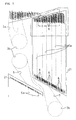
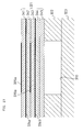
Next, the sectional construction of the ink-jet head 1 will
be described. FIG. 9 is a partial exploded view of the head
main body 1a of FIG. 4. FIG. 10 is an enlarged sectional view
when laterally viewing the region enclosed with an alternate
long and short dash line in FIG. 7. Referring to FIGS. 7 and 9,
a principal portion on the bottom side of the ink-jet head 1 has
a layered structure laminated with ten sheet materials in total,
i.e., from the top, an actuator unit 21, a cavity plate 22, a
base plate 23, an aperture plate 24, a supply plate 25, manifold
plates 26, 27, and 28, a cover plate 29, and a nozzle plate 30.
Of them, nine plates other than the actuator unit 21 constitute
a passage unit 4.
As described later in detail, the actuator unit 21 is
laminated with five piezoelectric sheets 41 to 45 (see FIG. 10)
and provided with electrodes so that only the uppermost layer
and the second layer neighboring the uppermost layer include
portions to be active when an electric field is applied
(hereinafter, simply referred to as "layer including active
layers (active portions)" ) and the remaining three layers are
inactive. The cavity plate 22 is made of metal, in which a
large number of substantially rhombic openings are formed
corresponding to the respective pressure chambers 10. The base
plate 23 is made of metal, in which a communication hole between
each pressure chamber 10 of the cavity plate 22 and the
corresponding aperture 12, and a communication hole between the
pressure chamber 10 and the corresponding ink ejection port 8
are formed. The aperture plate 24 is made of metal, in which,
in addition to apertures 12, communication holes are formed for
connecting each pressure chamber 10 of the cavity plate 22 with
the corresponding ink ejection port 8. The supply plate 25 is
made of metal, in which communication holes between each
aperture 12 and the corresponding sub-manifold channel 5a and
communication holes for connecting each pressure chamber 10 of
the cavity plate 22 with the corresponding ink ejection port 8
are formed. Each of the manifold plates 26, 27, and 28 is made
of metal, which defines an upper portion of each sub-manifold
channel 5a and in which communication holes are formed for
connecting each pressure chamber 10 of the cavity plate 22 with
the corresponding ink ejection port 8. The cover plate 29 is
made of metal, in which communication holes are formed for
connecting each pressure chamber 10 of the cavity plate 22 with
the corresponding ink ejection port 8. The nozzle plate 30 is
made of metal, in which tapered ink ejection ports 8 each
functioning as a nozzle are formed for the respective pressure
chambers 10 of the cavity plate 22.
These ten sheets 21 to 30 are put in layers with being
positioned to each other to form such an ink passage 32 as
illustrated in FIG. 7. The ink passage 32 first extends upward
from the sub-manifold channel 5a, then extends horizontally in
the aperture 12, then further extends upward, then again extends
horizontally in the pressure chamber 10, then extends obliquely
downward in a certain length to get apart from the aperture 12,
and then extends vertically downward toward the ink ejection
port 8.
Referring to FIG. 10, the actuator unit 21 includes five
piezoelectric sheets 41, 42, 43, 44, and 45 having the same
thickness of about 15 m. These piezoelectric sheets 41 to 45
are made into a continuous layered flat plate (continuous flat
layers) that is so disposed as to extend over many pressure
chambers 10 formed within one ink ejection region in the ink-jet
head 1. Since the piezoelectric sheets 41 to 45 are disposed so
as to extend over many pressure chambers 10 as the continuous
flat layers, the individual electrodes 35a and 35b can be
arranged at a high density by using, e.g., a screen printing
technique. Therefore, also the pressure chambers 10 formed at
positions corresponding to the individual electrodes 35a and 35b
can be arranged at a high density. This makes it possible to
print a high-resolution image. In this embodiment, each of the
piezoelectric sheets 41 to 45 is made of a lead zirconate
titanate (PZT)-base ceramic material having ferroelectricity.
Between the uppermost piezoelectric sheet 41 and the
piezoelectric sheet 42 neighboring downward the piezoelectric
sheet 41, an about 2 m-thick common electrode 34a is interposed
formed on the whole of the lower and upper faces of the
piezoelectric sheets. Also, between the piezoelectric sheet 43
neighboring downward the piezoelectric sheet 42 and the
piezoelectric sheet 44 neighboring downward the piezoelectric
sheet 43, an about 2 m-thick common electrode 34b is interposed
formed like the common electrode 34a. On the upper face of the
piezoelectric sheet 41, an about 1 m-thick individual electrode
35a is formed to correspond to each pressure chamber 10 (see
FIG. 6). The individual electrode 35a has a similar shape
(length: 850 m, width: 250 m) to that of the pressure chamber
10 in a plan view, so that a projection image of the individual
electrode 35a projected along the thickness direction of the
individual electrode 35a is included in the corresponding
pressure chamber 10. Further, between the piezoelectric sheets
42 and 43, an about 2 m-thick individual electrode 35b is
interposed formed like the individual electrode 35a. No
electrode is provided between the piezoelectric sheet 44
neighboring downward the piezoelectric sheet 43 and the
piezoelectric sheet 45 neighboring downward the piezoelectric
sheet 44, and on the lower face of the piezoelectric sheet 45.
Each of the electrodes 34a, 34b, 35a, and 35b is made of, e.g.,
an Ag-Pd-base metallic material.
The common electrodes 34a and 34b are grounded in a not-illustrated
region. Thus, the common electrodes 34a and 34b are
kept at the ground potential at a region corresponding to any
pressure chamber 10. The individual electrodes 35a and 35b in
each pair corresponding to a pressure chamber 10 are in contact
with leads (not illustrated) wired within the FPC 136
independently of another pair of individual electrodes so that
the potential of each pair of individual electrodes can be
controlled independently of that of another pair. The
individual electrodes 35a and 35b are connected to the driver IC
132 through the leads. In this case, the individual electrodes
35a and 35b in each pair vertically arranged may be connected to
the driver IC 132 through the same lead. In a modification,
many pairs of common electrodes 34a and 34b each having a shape
larger than that of a pressure chamber 10 so that the projection
image of each common electrode projected along the thickness
direction of the common electrode may include the pressure
chamber, may be provided for each pressure chamber 10. In
another modification, many pairs of common electrodes 34a and
34b each having a shape somewhat smaller than that of a pressure
chamber 10 so that the projection image of each common electrode
projected along the thickness direction of the common electrode
may be included in the pressure chamber, may be provided for
each pressure chamber 10. Thus, the common electrode 34a or 34b
may not always be a single conductive sheet formed on the whole
of the face of a piezoelectric sheet. In the above
modifications, however, all the common electrodes must be
electrically connected with one another so that the portion
corresponding to any pressure chamber 10 may be at the same
potential.
In the ink-jet head 1, the piezoelectric sheets 41 to 45 are
polarized in their thickness direction. That is, the actuator
unit 21 has a so-called unimorph structure in which the upper
(i.e., distant from the pressure chamber 10) three piezoelectric
sheets 41 to 43 are layers wherein active layers are present,
and the lower (i.e., near the pressure chamber 10) two
piezoelectric sheets 44 and 45 are made into inactive layers.
Therefore, when the individual electrodes 35a and 35b in a pair
are set at a positive or negative predetermined potential, if
the polarization is in the same direction as the electric field
for example, the electric field-applied portion in the
piezoelectric sheets 41 to 43 sandwiched by the common and
individual electrodes works as an active layer (pressure
generation portion) and contracts perpendicularly to the
polarization by the transversal piezoelectric effect. On the
other hand, since the piezoelectric sheets 44 and 45 are
influenced by no electric field, they do not contract in
themselves. Thus, a difference in strain perpendicular to the
polarization is produced between the upper piezoelectric sheets
41 to 43 and the lower piezoelectric sheets 44 and 45. As a
result, the whole of the piezoelectric sheets 41 to 45 is ready
to deform into a convex shape toward the inactive side (unimorph
deformation). At this time, as illustrated in FIG. 10, the
lowermost face of the piezoelectric sheets 41 to 45 is fixed to
the upper face of the partition (the cavity plate) 22
partitioning pressure chambers, as a result, the piezoelectric
sheets 41 to 45 deform into a convex shape toward the pressure
chamber side. Therefore, the volume of the pressure chamber 10
is decreased to raise the pressure of ink. The ink is thereby
ejected through the ink ejection port 8. After this, when the
individual electrodes 35a and 35b are returned to the same
potential as that of the common electrodes 34a and 34b, the
piezoelectric sheets 41 to 45 return to the original shape and
the pressure chamber 10 also returns to its original volume.
Thus, the pressure chamber 10 sucks ink therein through the
manifold channel 5.
In another driving method, all the individual electrodes 35a
and 35b are set in advance at a different potential from that of
the common electrodes 34a and 34b. When an ejecting request is
issued, the corresponding pair of individual electrodes 35a and
35b is once set at the same potential as that of the common
electrodes 34a and 34b. After this, at a predetermined timing,
the pair of individual electrodes 35a and 35b is again set at
the different potential from that of the common electrodes 34a
and 34b. In this case, at the timing when the pair of
individual electrodes 35a and 35b is set at the same potential
as that of the common electrodes 34a and 34b, the piezoelectric
sheets 41 to 45 return to their original shapes. The
corresponding pressure chamber 10 is thereby increased in volume
from its initial state (the state that the potentials of both
electrodes differ from each other), to suck ink from the
manifold channel 5 into the pressure chamber 10. After this, at
the timing when the pair of individual electrodes 35a and 35b is
again set at the different potential from that of the common
electrodes 34a and 34b, the piezoelectric sheets 41 to 45 deform
into a convex shape toward the pressure chamber 10. The volume
of the pressure chamber 10 is thereby decreased and the pressure
of ink in the pressure chamber 10 increases to eject ink.
On the other hand, in case that the polarization occurs in
the reverse direction to the electric field applied to the
piezoelectric sheets 41 to 43, the active layers in the
piezoelectric sheets 41 and 42 sandwiched by the individual
electrodes 35a and 35b and the common electrodes 34a and 34b are
ready to elongate perpendicularly to the polarization by the
transversal piezoelectric effect. As a result, the
piezoelectric sheets 41 to 45 deform into a concave shape toward
the pressure chamber 10. Therefore, the volume of the pressure
chamber 10 is increased to suck ink from the manifold channel 5.
After this, when the individual electrodes 35a and 35b return to
their original potential, the piezoelectric sheets 41 to 45 also
return to their original flat shape. The pressure chamber 10
thereby returns to its original volume to eject ink through the
ink ejection port 8.
Next, a manufacturing method of the ink-jet head 1 will be
described.
To manufacture the ink-jet head 1, a passage unit 4 and each
actuator unit 21 are separately manufactured in parallel and
then both are bonded to each other. To manufacture the passage
unit 4, each plate 22 to 30 to constitute the passage unit 4 is
subjected to etching using a patterned photoresist as a mask,
thereby forming openings as illustrated in FIGS. 7 and 9 in the
respective plates 22 to 30. After this, the nine plates 22 to
30 are put in layers with adhesives being interposed so as to
form therein ink passages 32. The nine plates 22 to 30 are
thereby bonded to each other to form a passage unit 4.
To manufacture each actuator unit 21, first, a conductive
paste to be individual electrodes 35b is printed in a pattern on
a ceramic green sheet to be a piezoelectric sheet 43. In
parallel with this, conductive pastes to be common electrodes
34a and 34b are printed in a pattern on ceramic green sheets to
be piezoelectric sheets 42 and 44. After this, five green
sheets to be piezoelectric sheets 41 to 45 are put in layers
with being positioned with a jig. The thus obtained layered
structure is then baked at a predetermined temperature. After
this, individual electrodes 35a are formed on the piezoelectric
sheet 41 of the baked layered structure. For example, the
individual electrodes 35a may be formed in the manner that a
conductive film is plated on the whole of one surface of the
piezoelectric sheet 41 and then unnecessary portions of the
conductive film are removed by laser patterning. Alternatively,
the individual electrodes 35a may be formed by depositing a
conductive film on the piezoelectric sheet 41 by PVD (Physical
Vapor Deposition) using a mask having openings at portions
corresponding to the respective individual electrodes 35a. To
this process, the manufacture of the actuator unit 21 is
completed.
Next, the actuator unit 21 manufactured as described above
is bonded to the passage unit 4 with an adhesive so that the
piezoelectric sheet 45 may be in contact with the cavity plate
22. At this time, both are bonded to each other on the basis of
marks for positioning formed on the surface of the cavity plate
22 of the passage unit 4 and the surface of the piezoelectric
sheet 41, respectively.
After this, through-holes are formed for connecting
vertically arranged corresponding individual electrodes 35a and
35b with each other. The through-holes are then filled up with
a conductive material. After this, for supplying electric
signals to the individual electrodes 35a and 35b and the common
electrodes 34a and 34b, the FPC 136 is bonded onto and
electrically connected with bonding positions corresponding to
the respective electrodes on the actuator unit 21 by soldering.
Further, through a predetermined process, the manufacture of the
ink-jet head 1 is completed.
As described above, differently from the other electrodes,
the only individual electrodes 35a are not baked together with
the ceramic materials to be the piezoelectric sheets 41 to 45.
The reason is as follows. That is, since the individual
electrodes 35a are exposed, they are apt to evaporate at a high
temperature upon baking. As a result, it is difficult to
control the thickness of them in comparison with the other
electrodes 34a, 34b, and 35b being covered with ceramic
materials. However, even the thickness of the other electrodes
34a, 34b, and 35b may somewhat decrease upon baking. Therefore,
it is difficult to form them into a small thickness if keeping
the continuity after baking is taken into consideration.
Contrastively, since the individual electrodes 35a are formed by
the above-described technique after baking, they can be formed
into a smaller thickness than the other electrodes 34a, 34b, and
35b. Thus, in the ink-jet head 1, by forming the individual
electrodes 35a in the uppermost layer into a smaller thickness
than the other electrodes 34a, 34b, and 35b, the deformation of
the piezoelectric sheets 41 to 43 including active layers is
hard to be restricted by the individual electrodes 35a.
Efficiencies (electrical efficiency and area efficiency) of the
actuator unit 21 are improved thereby.
In the ink-jet head 1, since the piezoelectric sheets 41 to
43 including active layers and the piezoelectric sheets 44 and
45 as the inactive layers are made of the same material, the
material need not be changed in the manufacturing process.
Thus, they can be manufactured through a relatively simple
process, and a reduction of manufacturing cost is expected.
Besides, for the reason that each of the piezoelectric sheets 41
to 43 including active layers and the piezoelectric sheets 44
and 45 as the inactive layers has substantially the same
thickness, a further reduction of cost can be intended by
simplifying the manufacturing process. This is because the
thickness control can easily be performed when the ceramic
materials to be the piezoelectric sheets are applied to be put
in layers.
Besides, in the ink-jet head 1, separate actuator units 21
corresponding to the respective ink ejection regions are bonded
onto the passage unit 4 to be arranged along the longitudinal
direction of the passage unit 4. Therefore, each of the
actuator units 21 apt to be uneven in dimensional accuracy and
in positional accuracy of the individual electrodes 35a and 35b
because they are formed by sintering or the like, can be
positioned to the passage unit 4 independently from another
actuator unit 21. Thus, even in case of a long head, the
increase in shift of each actuator unit 21 from the accurate
position on the passage unit 4 is restricted, and both can
accurately be positioned to each other. Therefore, as to even
an individual electrodes 35a and 35b relatively apart from a
mark, the individual electrodes 35a and 35b can not considerably
be shifted from the predetermined position to the corresponding
pressure chamber 10. As a result, good ink ejection performance
can be obtained and the manufacture yield of the ink-jet heads 1
is remarkably improved. On the other hand, differently from the
above, if a long-shaped actuator unit 21 is made like the
passage unit 4, the more the individual electrodes 35a and 35b
are apart from the mark, the larger the shift of the individual
electrodes 35a and 35b is from the predetermined position on the
corresponding pressure chamber 10 in a plan view when the
actuator unit 21 is laid over the passage unit 4. As a result,
the ink ejection performance of a pressure chamber 10 relatively
apart from the mark is deteriorated and thus the uniformity of
the ink ejection performance in the ink-jet head 1 is not
obtained.
In addition, in the ink-jet head 1 constructed as described
above, by sandwiching the piezoelectric sheets 41 to 43 by the
common electrodes 34a and 34b and the individual electrodes 35a
and 35b, the volume of each pressure chamber 10 can easily be
changed by the piezoelectric effect. Further, since each of the
piezoelectric sheets 41 to 43 including active layers is in a
shape of a continuous flat layer, it can easily be manufactured.
Besides, the ink-jet head 1 has the actuator units 21 each
having a unimorph structure in which the piezoelectric sheets 44
and 45 near each pressure chamber 10 are inactive and the
piezoelectric sheet 41 to 43 distant from each pressure chamber
10 include active layers. Therefore, the change in volume of
each pressure chamber 10 can be increased by the transversal
piezoelectric effect. As a result, in comparison with an ink-jet
head in which a layer including active layers is provided on
the pressure chamber 10 side and a inactive layer is provided on
the opposite side, lowering the voltage to be applied to the
individual electrodes 35a and 35b and/or high integration of the
pressure chambers 10 can be intended. By lowering the voltage
to be applied, the driver for driving the individual electrodes
35a and 35b can be made small in size and the cost can be held
down. In addition, each pressure chamber 10 can be made small
in size. Besides, even in case of a high integration of the
pressure chambers 10, a sufficient amount of ink can be ejected.
Thus, a decrease in size of the head 1 and a highly dense
arrangement of printing dots can be realized.
Further, in the ink-jet head 1, each actuator unit 21 has a
substantially trapezoidal shape. The actuator units 21 are
arranged in two lines in a zigzag manner so that the parallel
opposed sides of each actuator unit 21 extend along the
longitudinal direction of the passage unit 4, and the oblique
sides of each neighboring actuator units 21 overlap each other
in the lateral direction of the passage unit 4. Since the
oblique sides of each neighboring actuator units 21 thus overlap
each other, when the ink-jet head 1 moves along the lateral
direction of the ink-jet head 1 relatively to a print medium,
the pressure chambers 10 existing along the lateral direction of
the passage unit 4 can compensate each other. As a result, with
realizing high-resolution printing, a small-size ink-jet head 1
having a very narrow width can be realized.
Besides, since many pressure chambers 10 neighboring each
other are arranged in a matrix in the passage unit 4, the many
pressure chambers 10 can be disposed within a relatively small
size at a high density.
In the above-described ink-jet head 1, trapezoidal actuator
units are arranged in two lines in a zigzag manner. But, each
actuator unit may not be trapezoidal. Besides, actuator units
may be arranged in only one line along the longitudinal
direction of the passage unit. Actuator units may be arranged
in three or more lines in a zigzag manner.
Next, a second embodiment of the present invention will be
described. FIG. 11 is a plan view of a head main body of an
ink-jet head according to this embodiment. In the ink-jet head
and ink-jet printer according to this embodiment, since the
parts other than the head main body is similar to that of the
above-described first embodiment, the detailed description
thereof is omitted here.
Referring to FIG. 11, a head main body 201 of an ink-jet
head according to this embodiment has a rectangular shape in a
plan view extending in one direction (main scanning direction).
The head main body 201 includes a passage unit 204 in which a
large number of pressure chambers 210 and a large number of ink
ejection ports 208 are formed as will be described later. Onto
the upper face of the passage unit 204, two parallelogrammic
actuator units 221 (In FIG. 11, the right and left ones are
denoted by reference numerals 221a and 221b, respectively) are
bonded to neighbor each other. Each actuator unit 221 is
disposed so that its one side B extends along the longitudinal
direction of the head main body 201. The neighboring actuator
units 221 are so disposed as to be aligned with each other along
the width (shorter length) direction of the head main body 201
with their oblique sides C being close to each other. An ink
supply port 202 is open in the upper face of the passage unit
204. The ink supply port 202 is connected with an ink supply
source through a not-illustrated passage.
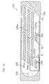
Referring to FIG. 12 that is a view of the head main body
201 at the reverse angle to FIG. 11 (a view from the printing
face side), two parallelogrammic ink ejection regions R1 are
provided in the lower face of the passage unit 204 to correspond
to the respective regions where the actuator units 221 are
disposed. A large number of small-diameter ink ejection ports
208 are arranged in the surface of each ink ejection region R1.
This embodiment shows a case of monochrome printing. Thus,
the ink supply port 202 is supplied with ink of a single color
(e.g., black). For performing multicolor printing, head main
bodies 201 corresponding in number to colors (for example, in
case of four colors of yellow, cyan, magenta, and black, four
head main bodies 201) are aligned along the lateral direction of
the passage unit. The head main bodies 201 are supplied with
color inks different from one another to print.
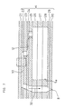
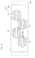
FIG. 13 is a sectional view illustrating the internal
construction of the passage unit 204. Referring to FIG. 13, a
manifold channel 205 is formed in the passage unit 204. The
manifold channel 205 communicates with an ink supply source
through the ink supply port 202, as a result, the manifold
channel 205 is always filled up with ink. The ink supply port
202 is preferably provided with a filter for catching dust and
dirt contained in ink.
The manifold channel 205 is formed in the most part of
passage unit 204 to extend over the two ink ejection regions R1.
In part of the manifold channel 205 corresponding to each ink
ejection region R1, a large number of slender parallelogrammic
island portions 205a are formed to be arranged at regular
intervals. The length of each island portion 205a is along the
longitudinal direction of the passage unit 204. In this
construction, ink supplied through the ink supply port 202
passes between each neighboring island portions 205a in the
manifold channel 205, and then it is distributed to pressure
chambers 210 as described later formed in the passage unit 204
in each ink ejection region R1.
Referring to FIG. 15, each ink ejection port 208 is made
into a tapered nozzle. The ink ejection port 208 communicates
with a manifold channel 205 through a pressure chamber 210
having a substantially parallelogrammic shape in a plan view and
an aperture 212. In this construction, ink is supplied from the
manifold channel 205 to the pressure chamber 210 through the
aperture 212. By driving an actuator unit 221 as will be
described later, jet energy is applied to ink in the pressure
chamber 210 to jet ink through the ink ejection port 208.
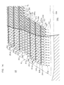
FIG. 14 illustrates a detailed construction of the region
denoted by reference Q in FIG. 13. As apparent from FIG. 14, in
a region of the upper face of the passage unit 204 corresponding
to an ink ejection region R1, a large number of pressure
chambers 210 are arranged in a matrix to neighbor each other.
Since the pressure chambers 210 are formed at a different level
from that of the apertures 212 as illustrated in FIG. 15, such
an arrangement as illustrated in FIG. 14 is possible in which
each aperture 212 connected with a pressure chamber 210 overlaps
another pressure chamber 210. As a result, a highly dense
arrangement of the pressure chambers 210 can be realized and
this may contribute a decrease in size of the head main body 201
and an increase in resolution of an image to be formed.
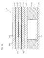
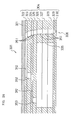
FIG. 15 illustrates a specific construction of a passage
from a manifold channel 205 to an ink ejection port 208.
Referring to FIG. 15, the passage unit 204 is laminated with
nine sheet materials in total, i.e., a cavity plate 222, a base
plate 223, an aperture plate 224, a supply plate 225, manifold
plates 226, 227, and 228, a cover plate 229, and a nozzle plate
230. The above-described actuator units 221 are bonded to the
upper face of the passage unit 204 to constitute a head main
body 201. The detailed construction of each actuator unit 221
will be described later.
A parallelogrammic opening is formed in the cavity plate 222
to form a pressure chamber 210 as described above. A tapered
ink ejection port 208 is formed in the nozzle plate 230 with a
press. Communication holes 251 are formed through each of the
plates 223 to 229 between the plates 222 and 230. The pressure
chamber 210 communicates with the ink ejection port 208 through
the communication holes 251. An aperture 212 as an elongated
hole is formed in the aperture plate 224. One end of the
aperture 212 is connected with an end portion of the pressure
chamber 210 (opposite to the end portion connecting with the ink
ejection port 208) through a communication hole 252 formed in
the base plate 223. The aperture 212 is for properly
controlling the amount of ink to be supplied to the pressure
chamber 210 and preventing too much or too little ink from being
jetted through the ink ejection port 208. A communication hole
253 is formed in the supply plate 225. The communication hole
253 connects the other end of the aperture 212 with the manifold
channel 205.
Each of the nine plates 222 to 230 constituting the passage
unit 204 is made of metal. The pressure chamber 210, the
aperture 212, and the communication holes 251, 252, and 253 are
formed by selectively etching each metallic plate using a mask
pattern. The nine plates 222 to 230 are put in layers and
bonded to each other with being positioned to each other so that
the passage as illustrated in FIG. 15 is formed therein.
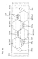
Referring to FIG. 16, each actuator unit 221 includes five
piezoelectric sheets 241 to 245 having the same thickness of
about 15 m. These piezoelectric sheets 241 to 245 are made
into continuous flat layers. One actuator unit 221 is disposed
to extend over many pressure chambers 210 formed in one ink
ejection region R1 of the head main body 201. This can realize
a highly dense arrangement of individual electrodes 235a and
235b in the actuator unit 221. Each of the piezoelectric sheets
241 to 245 is made of a lead zirconate titanate (PZT)-base
ceramic material having ferroelectricity.
Between the first and second piezoelectric sheets 241 and
242 from the top, an about 2 m-thick common electrode 234a is
interposed formed on substantially the whole of the lower and
upper faces of the piezoelectric sheets. Also, between the
third and fourth piezoelectric sheets 243 and 244, an about 2
m-thick common electrode 234b is interposed. On the upper face
of the first piezoelectric sheet 241, an about 1 m-thick
individual electrode 235a is formed to correspond to each
pressure chamber 210. As illustrated in FIG. 13, the individual
electrode 235a has a similar shape to that of the pressure
chamber 210 in a plan view though the individual electrode 235a
is somewhat smaller than the pressure chamber 210. The
individual electrode 235a is disposed such that the center of
the individual electrode 235a coincides with the center of the
corresponding pressure chamber 210. Further, between the second
and third piezoelectric sheets 242 and 243, an about 2 m-thick
individual electrode 235b is interposed formed like the
individual electrode 235a. The portion where the individual
electrodes 235a and 235b are disposed corresponds to a pressure
generation portion A for applying pressure to ink in the
pressure chamber 210. No electrode is provided between the
fourth and fifth piezoelectric sheets 244 and 245, and on the
lower face of the fifth piezoelectric sheet 245. Each of the
electrodes 234a, 234b, 235a, and 235b is made of, e.g., an Ag-Pd-base
metallic material.
The common electrodes 234a and 234b are grounded in a not-illustrated
region. Thus, the common electrodes 234a and 234b
are kept at the ground potential at a region corresponding to
any pressure chamber 210. In order that the individual
electrodes 235a and 235b in each pair corresponding to a
pressure chamber 210 can be controlled in potential
independently of another pair, they are connected with a
suitable driver IC through a lead provided separately for each
pair of individual electrodes 235a and 235b.
In the head main body 201, the piezoelectric sheets 241 to
245 are to be polarized in their thickness. That is, the
actuator unit 221 has a so-called unimorph structure in which
the upper (i.e., distant from the pressure chamber 210) three
piezoelectric sheets 241 to 243 are layers including active
layers, and the lower (i.e., near the pressure chamber 210) two
piezoelectric sheets 244 and 245 are made into inactive layers.
In this structure, when the individual electrodes 235a and
235b in a pair are set at a positive or negative predetermined
potential, if the polarization is in the same direction as the
electric field for example, the portion (an active layer, i.e.,
a pressure generation portion) in the piezoelectric sheets 241
to 243 sandwiched by the common and individual electrodes
contracts perpendicularly to the polarization. On the other
hand, since the inactive piezoelectric sheets 244 and 245 are
influenced by no electric field, they do not contract in
themselves. Thus, a difference in strain along the polarization
is produced between the upper piezoelectric sheets 241 to 243
and the lower piezoelectric sheets 444 and 245. As a result,
the whole of the piezoelectric sheets 241 to 245 is ready to
deform into a convex shape toward the inactive side (unimorph
deformation). At this time, since the lower face of the
lowermost piezoelectric sheet 245 is fixed to the upper face of
the partition partitioning pressure chambers 210, the pressure
generation portion A of the piezoelectric sheets 241 to 245
deforms into a convex shape toward the pressure chamber 210 side
to decrease the volume of the pressure chamber 210. As a
result, the pressure of ink is raised and ink is thereby ejected
through the ink ejection port 208. After this, when application
of the driving voltage to the individual electrodes 235a and
235b is stopped, the piezoelectric sheets 241 to 245 return to
the original shape and the pressure chamber 210 also returns to
its original volume. Thus, the pressure chamber 210 sucks ink
therein through the manifold channel 205.
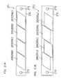
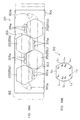
Next, the shape of the two actuator units 221a and 221b and
the arrangement of individual electrodes 235a and 235b (in other
words, the arrangement of pressure generation portions A) will
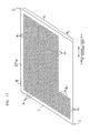
be described. FIG. 17 illustrates the shape of an actuator unit
221a and the arrangement of pressure generation portions. FIG.
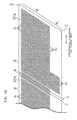
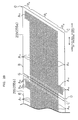
18 shows the relation between a seam portion between the
actuator units 221a and 221b and pressure generation portions in
an additional region.
The head main body 201 includes two actuator units 221a and
221b as described above. The two actuator units 221a and 221b
have quite the same shape and the same arrangement of pressure
generation portions A.
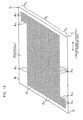
As illustrated in FIGS. 11 and 17, the actuator unit 221a is
parallelogrammic, which is disposed so that its one side B
extends in parallel with the longitudinal direction of the
passage unit 204 and its other side C inclines to the
longitudinal direction of the passage unit 204. As illustrated
in FIG. 17, in the actuator unit 221a, two regions P1 and P2 are
provided that are separated in the lateral direction of the
passage unit 204 by a straight line along the longitudinal
direction of the passage unit 204. That is, the regions P1 and
P2 neighbor each other in the lateral direction of the passage
unit 204.
In the basic region P1 of the two regions P1 and P2, a large
number of pressure generation portions A1 are arranged with
neighboring each other in a matrix along the longitudinal
direction of the passage unit 204 and along the other side C of
the parallelogram.
In the other region (additional region P2) than the basic
region P1, pressure generation portions A2 are arranged with
neighboring each other in a matrix only in the vicinity of an
acute corner D of the parallelogram near to the actuator unit
221b.
When the two actuator units 221a and 221b thus constructed
are arranged in line along the longitudinal direction of the
passage unit 204 as illustrated in FIG. 11, as illustrated in
FIG. 18, the pressure generation portions A2 of the additional
region P2 provided in the actuator unit 221a are in a place
corresponding to a region (hatched region G in FIG. 18) where no
pressure generation portion A can be disposed in the basic
region P1 because it is in the seam between the actuator units
221a and 221b. That is, the pressure generation portions A2 of
the additional region P2 are disposed to correspond to a gap
portion G between the pressure generation portions A1 of the
basic region P1 provided in the actuator unit 221a and the
pressure generation portions A1 of the basic region P1 provided
in the neighboring actuator unit 221b. Thus, although no
separate actuator unit is provided for ejecting ink through the
gap portion G, the head main body 201 can be provided that can
perform printing with no break through the longitudinal
direction of the passage unit.
In other words, since no pressure generation portion can be
disposed in the region (region G) near the seam portion between
the actuator units 221a and 221b, no pressure chamber 210 and no
ink ejection port 208 also can be disposed in that region.
Therefore, if the pressure generation portions A2 were not
disposed in the additional region P2 provided in the actuator
unit 221a, printing in the portion corresponding to the gap
portion G cannot be done, as a result, a portion where ink
ejection is impossible is produced in the seam portion between
the actuator units 221a and 221b. But, since the pressure
generation portions A2 are disposed in the additional region P2
provided in the actuator unit 221a in a portion overlapping that
region G in the lateral direction of the passage unit, there is
no portion where ink ejection is impossible. As a result, an
image with no break can be formed on a paper.
As described above, in this embodiment, the actuator unit
221 includes lines in each of which a large number of pressure
generation portions A1 and A2 are arranged along the
longitudinal direction of the passage unit 204. As for the
lengths of these lines along the longitudinal direction of the
passage unit 204, each line in the basic region P1 is longer
than each line in the additional region P2. Besides, as for the
number of lines along the lateral direction of the passage unit
204, the number of lines in the additional region P2 is the same
as the number of lines that might exist in the length of the
corresponding region G along the lateral direction of the
passage unit 204. Therefore, if an imaginary straight line is
drawn to extend along the lateral direction of the passage unit
204, the number of lines that the imaginary straight line
crosses in the region where the neighboring actuator units 221a
and 221b overlap each other is the same as the number of lines
that the imaginary straight line crosses in the region where the
neighboring actuator units 221a and 221b do not overlap each
other.
The above-described feature can be achieved only by
arranging two actuator units 221a and 221b having the same
construction. Thus, the arrangement of parts can be simplified
and the cost and the number of process steps necessary for
designing or manufacturing the actuator units 221a and 221b can
be reduced.
The arrangement of pressure generation portions A in the
actuator unit 221 described in this embodiment is by way of
example. For instance, such an actuator unit 255 as illustrated
in FIG. 19 may be used. FIG. 19 illustrates another example of
arrangement of pressure generation portions in an actuator unit.
FIG. 20 shows the relation between a seam portion between
actuator units and pressure generation portions in an additional
region in the arrangement of FIG. 19.
The actuator unit 255a of FIG. 19 is divided into three
regions P11, P12, and P13 in the lateral direction of the
passage unit. The middle region P11 in the lateral direction of
the passage unit is used as a basic region and the remaining
regions P12 and P13 are used as additional regions.
Like the arrangement in FIG. 17, in the basic region P11, a
large number of pressure generation portions A11 are arranged
with neighboring each other in a matrix along the longitudinal
direction of the passage unit and along the other side C of the
parallelogram. In an additional region P12, pressure generation
portions A12 are arranged with neighboring each other in a
matrix in the vicinity of an acute corner D of the parallelogram
near to the actuator unit 255b. In the other additional region
P13, pressure generation portions A13 are arranged with
neighboring each other in a matrix in the vicinity of an acute
corner D of the parallelogram far from the actuator unit 255b.
Therefore, as illustrated in FIG. 20, the pressure
generation portions A12 of the additional region P12 of the
actuator unit 255a and the pressure generation portions A13 of
the additional region P13 of the actuator unit 255b are disposed
in a gap portion G between the pressure generation portions A11
of the basic region P11 provided in the actuator unit 255a and
the pressure generation portions A11 of the basic region P11
provided in the neighboring actuator unit 255b. Thus, the head
main body 201 can be provided with which ink can be ejected with
no break through the longitudinal direction of the passage unit.
Besides, this embodiment also can bring about the same
advantages as those of the above-described first embodiment.
More specifically, since the two actuator units 255a and 255b
are arranged along the longitudinal direction of the passage
unit 204, even in case of a long passage unit 204, high accuracy
can be obtained in positioning of the actuator units 255a and
255b to the passage unit 204. Therefore, good ink ejection
performance can be obtained and the manufacture yield of ink-jet
heads 201 can be remarkably improved. In addition, by
sandwiching the piezoelectric sheets 241 to 243 between the
common electrodes 234a and 234b and the individual electrodes
235a and 235b, the volume of each pressure chamber 210 can
easily be changed by the piezoelectric effect. Besides, the
piezoelectric sheets 241 to 243 including active layers can
easily be manufactured because they are continuous flat layers.
Further, since an actuator unit 221 of a unimorph structure is
provided in which the piezoelectric sheets 244 and 245 near to
each pressure chamber 210 are inactive and the piezoelectric
sheets 241 to 243 far from each pressure chamber 210 are layers
including active layers, the change in volume of each pressure
chamber 210 can be increased by the transversal piezoelectric
effect, and lowering the voltage to be applied to the individual
electrodes 235a and 235b and/or high integration of the pressure
chambers 210 can be intended. Further, in the passage unit 204,
since a large number of pressure chambers 210 neighboring each
other are arranged in a matrix, the many pressure chambers 210
can be disposed at a high density within a relatively small
size.
In this embodiment, two actuator units are arranged. But,
three or more actuator units may be arranged of course.
Arrangement of many actuator units can bring about a long ink-jet
head. Such a long ink-jet head is advantageous because it
can perform printing onto even a large-size paper at a high
speed.
FIGS. 21A and 21B illustrate head main bodies 271 and 272
according to modifications of the second embodiment, in which
four actuator units 261 (In FIGS. 21A and 21B, they are denoted
by reference numerals 261a, 261b, 261c, and 261d, respectively,
in order from the right) each constructed like an actuator unit
221 or 255 are arranged in line on and bonded to passage units
274 having, near their both ends, ink supply ports 273. Such an
actuator unit 261, like an actuator unit 221 or 255, can be used
in common to passage units different in length, e.g., from a
relatively short passage unit as illustrated in FIG. 11 to a
long passage unit as illustrated in FIG. 21A. Thus, such an
actuator unit is high in applicability as a component and this
can reduce the manufacture cost.
In the head main bodies 201 and 271 as illustrated in FIGS.
11 and 21A, actuator units are arranged on a passage unit in a
straight line with being aligned in the lateral direction of the
passage unit. However, as in a head main body 272 illustrated
in FIG. 21B for example, actuator units 261a, 261b, 261c, and
261d may be arranged in a zigzag form. But, from the viewpoint
of making an ink-jet head compact, the arrangement as
illustrated in FIG. 11 or 21A is preferable in which actuator
units are arranged in a straight line along the longitudinal
direction of the passage unit with being regularly aligned in
the lateral direction of the passage unit. Particularly in case
of the arrangement of FIG. 11 or 21A, the width of the ink-jet
head can be made small. Therefore, when two or more ink-jet
heads are arranged along their width to be supplied with inks of
different colors for multicolor printing, they can be disposed
within a compact space. This is further advantageous because
occurrence of a shear in color of an image can be lessened even
when a paper runs in an oblique state upon printing.
Next, a third embodiment of the present invention will be
described. FIG. 22 is a plan view of a head main body of an
ink-jet head according to this embodiment. In the ink-jet head
and ink-jet printer according to this embodiment, since the
parts other than the head main body is similar to that of the
above-described first embodiment, the detailed description
thereof is omitted here.
Referring to FIG. 22, a head main body 301 of an ink-jet
head according to this embodiment has a rectangular shape in a
plan view extending in one direction. The head main body 301
includes a passage unit 304 in which a large number of pressure
chambers 310 and a large number of ink ejection ports 308 are
formed as will be described later. On the upper face of the
passage unit 304, four regular-hexagonal actuator units 321 (In
FIG. 22, they are denoted by reference numerals 321a, 321b,
321c, and 321d, respectively, in order from the right) are
arranged in two lines in a zigzag manner and they are bonded to
the upper face of the passage unit 304. Each actuator unit 321
is disposed so that its opposed parallel sides (upper and lower
sides) extend along the longitudinal direction of the head main
body 301. Each neighboring actuator units 321 are disposed so
that their oblique sides is to be close to each other and have
overlapping portions in the lateral direction of the passage
unit.
Referring to FIG. 23 that is a view of the passage unit 304
at the reverse angle to FIG. 22 (a view from the printing face
side), four hexagonal ink ejection regions R2 are provided in
the lower face of the passage unit 304 to correspond to the
respective regions where the actuator units 321 are disposed. A
large number of small-diameter ink ejection ports 308 are
arranged in the surface of each ink ejection region R2. A base
block 302 is disposed on the upper face of the head main body
301. A pair of ink reservoirs 303 each having a slender shape
along the longitudinal direction of the head main body 301 is
provided in the base block 302. An opening 303a is formed in
the upper face of the base block 302 at one end of each ink
reservoir 303. Each opening 303a is connected with a not-illustrated
ink tank, as a result, each ink reservoir 303 is
always filled up with ink.
FIG. 24 is a sectional view illustrating the internal
construction of the passage unit 304. Referring to FIG. 24,
manifold channels 305 as ink supply sources are formed in the
passage unit 304. Each manifold channel 305 communicates with
an ink reservoir 303 through the corresponding opening 305a
formed in the upper face of the passage unit 304. Each opening
305a is preferably provided with a filter for catching dust and
dirt contained in ink.
Each manifold channel 305 branches at its opening 305a to
supply ink to a number of pressure chambers 310 as described
later. When each hexagonal ink ejection region R2 illustrated
in FIG. 23 is evenly divided vertically in FIG. 23 into two
regions, one manifold channel 305 is formed so as to correspond
to one of the two regions. Eight manifold channels 305 are
provided and each of them is so designed in shape as to
distribute and supply ink to all pressure chambers 310 included
in the corresponding region.
The ink ejection port 308 being in one half region in the
lateral direction of the passage unit communicates with one of
the ink reservoirs 303 in a pair through a manifold channel 305.
The ink ejection port 308 being in the other half region in the
lateral direction of the ink-jet head communicates with the
other ink reservoir 303. By thus arranging the manifold
channels 305, the openings 305a, and the ink reservoirs 303, two
printing modes can be realized: (1) a mode in which the ink
reservoirs 303 in the pair are supplied with ink of the same
color to perform monochrome high-resolution printing; and (2) a
mode in which the ink reservoirs 303 in the pair are supplied
with ink of different colors to perform two-color printing with
the single head main body 301. This is a wide-usable
construction.
Referring to FIG. 26, each ink ejection port 308 is made
into a tapered nozzle. The ink ejection port 308 communicates
with a manifold channel 305 through a pressure chamber 310
having a nearly rhombic shape in a plan view and an aperture
312. In this construction, ink is supplied to the manifold
channel 305 through the ink reservoir 303 and further supplied
from the manifold channel 305 to the pressure chamber 310
through the aperture 312. By driving an actuator unit 321 as
will be described later, jet energy is applied to ink in the
pressure chamber 310 to jet ink through the ink ejection port
308.
FIG. 25 illustrates a detailed construction of the region
denoted by reference E in FIG. 24. As apparent from FIG. 25, in
a region of the upper face of the passage unit 304 corresponding
to an ink ejection region R2, a large number of pressure
chambers 310 are arranged in a matrix to neighbor each other.
Since the pressure chambers 310 are formed at a different level
from that of the apertures 312 as illustrated in FIG. 26, an
arrangement is possible in which each aperture 312 connected
with a pressure chamber 310 overlaps another pressure chamber
310. As a result, a highly dense arrangement of the pressure
chambers 310 can be realized and this may contribute a decrease
in size of the head main body 301 and an increase in resolution
of an image to be formed.
FIG. 26 illustrates a specific construction of a passage
from a manifold channel 305 to an ink ejection port 308.
Referring to FIG. 26, the passage unit 304 is laminated with
nine sheet materials in total, i.e., a cavity plate 322, a base
plate 323, an aperture plate 324, a supply plate 325, manifold
plates 326, 327, and 328, a cover plate 329, and a nozzle plate
330. The above-described actuator units 321 are bonded to the
upper face of the passage unit 304 to constitute a head main
body 301. The detailed construction of each actuator unit 321
will be described later.
A rhombic opening is formed in the cavity plate 322 to form
a pressure chamber 310. A tapered ink ejection port 308 is
formed in the nozzle plate 330 with a press. Communication
holes 351 are formed through each of the plates 323 to 329
between the plates 322 and 330. The pressure chamber 310
communicates with the ink ejection port 308 through the
communication holes 351. An aperture 312 as an elongated hole
is formed in the aperture plate 324. One end of the aperture
312 is connected with an end portion of the pressure chamber 310
(opposite to the end portion connecting with the ink ejection
port 308) through a communication hole 352 formed in the base
plate 323. The aperture 312 is for properly controlling the
amount of ink to be supplied to the pressure chamber 310 and
preventing too much or too little ink from being jetted through
the ink ejection port 308. A communication hole 353 is formed
in the supply plate 325. The communication hole 353 connects
the other end of the aperture 312 with the manifold channel 305.
Each of the nine plates 322 to 330 constituting the passage
unit 304 is made of metal. The above-described pressure chamber
310, aperture 312, and communication holes 351, 352, and 353 are
formed by selectively etching each metallic plate using a mask
pattern. The nine plates 322 to 330 are put in layers and
bonded to each other with being positioned to each other so that
the passage as illustrated in FIG. 26 is formed therein.
Next, the structure of each actuator unit 321 will be
described. Referring to FIG. 27, the actuator unit 321 includes
five piezoelectric sheets 341 to 345 having the same thickness
of about 15 m. These piezoelectric sheets 341 to 345 are made
into continuous flat layers. One actuator unit 321 is disposed
to extend over many pressure chambers 310 formed in one ink
ejection region R2 of the head main body 301. This can realize
a highly dense arrangement of individual electrodes 335a and
335b. Each of the piezoelectric sheets 341 to 345 is made of a
lead zirconate titanate (PZT)-base ceramic material having
ferroelectricity.
Between the first and second piezoelectric sheets 341 and
342 from the top, an about 2 m-thick common electrode 334a is
interposed formed on substantially the whole of the lower and
upper faces of the piezoelectric sheets. Also, between the
third and fourth piezoelectric sheets 343 and 344, an about 2
m-thick common electrode 234b is interposed. On the upper face
of the first piezoelectric sheet 341, an about 1 m-thick
individual electrode 335a is formed to correspond to each
pressure chamber 310. As illustrated in FIG. 24, the individual
electrode 335a has a similar shape to that of the pressure
chamber 310 in a plan view though the individual electrode 335a
is somewhat smaller than the pressure chamber 310. The
individual electrode 335a is disposed such that the center of
the individual electrode 335a coincides with the center of the
corresponding pressure chamber 310. Further, between the second
and third piezoelectric sheets 342 and 343, an about 2 m-thick
individual electrode 335b is interposed formed like the
individual electrode 335a. No electrode is provided between the
fourth and fifth piezoelectric sheets 344 and 345, and on the
lower face of the fifth piezoelectric sheet 345. Each of the
electrodes 334a, 334b, 335a, and 335b is made of, e.g., an Ag-Pd-base
metallic material.
The common electrodes 334a and 334b are grounded in a not-illustrated
region. Thus, the common electrodes 334a and 334b
are kept at the ground potential at a region corresponding to
any pressure chamber 310. In order that the individual
electrodes 335a and 335b in each pair corresponding to a
pressure chamber 310 can be controlled in potential
independently of another pair, they are connected with a
suitable driver IC (not illustrated) through a lead provided
separately for each pair of individual electrodes 335a and 335b.
In the head main body 301, the piezoelectric sheets 341 to
345 are to be polarized in their thickness. That is, the
actuator unit 321 has a so-called unimorph structure in which
the upper (i.e., distant from the pressure chamber 310) three
piezoelectric sheets 341 to 343 are layers including active
layers, and the lower (i.e., near the pressure chamber 310) two
piezoelectric sheets 344 and 345 are made into inactive layers.
In this structure, when the individual electrodes 335a and
335b in a pair are set at a positive or negative predetermined
potential, if the polarization is in the same direction as the
electric field for example, the portion (an active layer, i.e.,
a pressure generation portion) in the piezoelectric sheets 341
to 343 sandwiched by the common and individual electrodes
contracts perpendicularly to the polarization. On the other
hand, since the inactive piezoelectric sheets 344 and 345 are
influenced by no electric field, they do not contract in
themselves. Thus, a difference in strain perpendicular to the
polarization is produced between the upper piezoelectric sheets
341 to 343 and the lower piezoelectric sheets 344 and 345. As a
result, the whole of the piezoelectric sheets 341 to 345 is
ready to deform into a convex shape toward the inactive side
(unimorph deformation). At this time, since the lower face of
the lowermost piezoelectric sheet 345 is fixed to the upper face
of the partition partitioning pressure chambers 310, the
piezoelectric sheets 341 to 345 deform into a convex shape
toward the pressure chamber 310 side to decrease the volume of
the pressure chamber 310. As a result, the pressure of ink is
raised and ink is thereby ejected through the ink ejection port
308. After this, when application of the driving voltage to the
individual electrodes 335a and 335b is stopped, the
piezoelectric sheets 341 to 345 return to the original shape and
the pressure chamber 310 also returns to its original volume.
Thus, the pressure chamber 310 sucks ink therein through the
manifold channel 305.
To manufacture each actuator unit 321, first, ceramic green
sheets to be piezoelectric sheets 341 to 345 are put in layers
and then baked. At this time, a metallic material to be
individual electrodes 335a or a common electrode 334a or 334b is
printed into a pattern on each ceramic green sheet at need.
After this, a metallic material to be individual electrodes 335a
is formed by plating on the whole of the upper face of the first
piezoelectric sheet 341 and then unnecessary portions of the
material are removed by laser patterning. Alternatively, a
metallic material to be individual electrodes 335a is deposited
using a mask having openings at portions corresponding to the
respective individual electrodes 335a.
The actuator unit 321 thus manufactured is very brittle
because it is made of ceramic. In particular, since corners of
the actuator unit 321 are very easy to be broken off, very
delicate handling is required upon manufacture and assembling in
order that any corner must not be brought into contact with
another component.
However, as illustrated in FIG. 28A that is a plan view of
the actuator unit 321, in the ink-jet head according to this
embodiment, the actuator unit 321 has a substantially regular-hexagonal
profile. Any of six straight portions (sides) L1 to
L6 included in this profile is connected with a neighboring
straight portion L at about 120 . As a result, since any of the
six corners (portions of each neighboring straight portions L
crossing each other) 1 to 6 is not acute, it is hard to be
broken off. Therefore, the actuator unit 321 as an expensive
precise component may not be easy to be broken in the middle of
manufacture process. This may contribute a reduction of
manufacture cost.
The above effect is not obtained only when any of the
corners 1 to 6 is formed into 120 . If a corner n is formed
into 90 or more, the corner n is hard to be broken off.
Therefore, for making any of the six corners 1 to 6 hard to be
broken off, it suffices that any of the six straight portions L1
to L6 is connected with a neighboring straight portion L at the
right angle or an obtuse angle (the minimum value of the angles
1 to 6 at the crossing portions is 90 or more). The
hexagonal profile can freely be changed as far as the above
condition is satisfied. FIG. 28B illustrates an actuator unit
355 as an example in which the above condition is satisfied.
Besides, this embodiment also can bring about the same
advantages as those of the above-described first embodiment.
More specifically, since the four actuator units 321 are
arranged along the longitudinal direction of the passage unit
304, even in case of a long passage unit 304, high accuracy can
be obtained in positioning of the actuator units 321 to the
passage unit 304. Therefore, good ink ejection performance can
be obtained and the manufacture yield of ink-jet heads 301 can
be remarkably improved. Besides, by sandwiching the
piezoelectric sheets 341 to 343 between the common electrodes
334a and 334b and the individual electrodes 335a and 335b, the
volume of each pressure chamber 310 can easily be changed by the
piezoelectric effect. Besides, the piezoelectric sheets 341 to
343 including active layers can easily be manufactured because
they are continuous flat layers. Besides, since an actuator
unit 321 of a unimorph structure is provided in which the
piezoelectric sheets 344 and 345 near to each pressure chamber
310 are inactive and the piezoelectric sheets 341 to 343 far
from each pressure chamber 310 are layers including active
layers, the change in volume of each pressure chamber 310 can be
increased by the transversal piezoelectric effect, and lowering
the voltage to be applied to the individual electrodes 335a and
335b and/or high integration of the pressure chambers 310 can be
intended. Further, in the passage unit 304, since a large
number of pressure chambers 310 neighboring each other are
arranged in a matrix, the many pressure chambers 310 can be
disposed at a high density within a relatively small size.
In the present invention, the profile of each actuator unit
is not limited to a hexagon. That is, the number of straight
portion L may be not six but five, seven, eight, or more.
Hereinafter, modifications in profile of each actuator unit will
be described with reference to FIGS. 28 to 30. In the below
modifications, the same components as in the above-described
third embodiment are denoted by the same reference numerals as
in the third embodiment, respectively.
FIG. 29A is a plan view of a head main body in which each
actuator unit is made into a heptagonal shape. FIG. 29B is a
plan view of an actuator unit included in the head main body of
FIG. 29A. As apparent from FIGS. 29A and 29B, in this
modification, the components of the head main body 361 other
than the actuator units 362 (In FIGS. 29A, they are denoted by
reference numerals 362a, 362b, 362c, and 362d, respectively, in
order from the right) are constructed like those of the head
main body 301 of the third embodiment.
Referring to FIG. 29B, each actuator unit 362 has its
profile in which one corner of a hexagon according to the above-described
embodiment has been cut off along a straight line. As
a result, the number of straight portion L is seven (L8 to L14),
and as for the angle of each corner, 8 to 12 are about 120
and 13 and 14 are about 150 .
FIG. 30A is a plan view of a head main body in which each
actuator unit is made into an octagonal shape. FIG. 30B is a
plan view of an actuator unit included in the head main body of
FIG. 30A. As apparent from FIGS. 30A and 30B, in this
modification, the components of the head main body 371 other
than the actuator units 372 (In FIGS. 30A, they are denoted by
reference numerals 372a, 372b, 372c, and 372d, respectively, in
order from the right) are constructed like those of the head
main body 301 of the third embodiment.
Referring to FIG. 30B, each actuator unit 372 has its
profile in which two corners of a hexagon according to the
above-described embodiment has been cut off along straight
lines. As a result, the number of straight portion L is eight
(L15 to L22), and as for the angle of each corner, 15, 16,
19, and 20 are about 120 and 17, 18, 21, and 22 are about
150 . In the above-described two modifications, since the angle
of each corner of each cut-off portion is 150 , which is larger
than that of the above-described hexagonal actuator unit 321,
the corner is harder to be broken off than that of the above-described
hexagonal actuator unit 321.
FIG. 31A is a plan view of a head main body in which two
interconnecting portions of neighboring straight portions L in
the actuator unit of the above-described third embodiment have
been made into rounded portions F. FIG. 31B is a plan view of
an actuator unit included in the head main body of FIG. 31A. As
apparent from FIGS. 31A and 31B, in this modification, the
components of the head main body 381 other than the actuator
units 382 (In FIGS. 31A, they are denoted by reference numerals
382a, 382b, 382c, and 382d, respectively, in order from the
right) are constructed like those of the head main body 301 of
the second embodiment.
Referring to FIG. 31B, each actuator unit 382 has six
straight portions L23 to L28. Two interconnecting portions of
neighboring straight portions L (L23 and L28, and L25 and L26)
in the actuator unit 382 are made into rounded portions F, where
neighboring straight portions L are smoothly interconnected.
Each rounded portion F is very hard to be broken off. Also in
this case, the angle between each neighboring straight portions
L, including two straight portions on both sides of each rounded
portion F, ( 23 to 27), is more than 90 (about 120 ).
Next, the fourth embodiment of the present invention will be
described with reference to FIG. 32. In the ink-jet head and
ink-jet printer according to this embodiment, since the parts
other than the head main body is similar to that of the above-described
first embodiment, the detailed description thereof is
omitted here.
A head main body 401 as illustrated in FIG. 32 includes a
passage unit 404 in which a large number of pressure chambers
and a large number of ink ejection ports are formed like the
above-described embodiments. Onto the upper face of the passage
unit 404, two parallelogrammic actuator units 421 (In FIG. 32,
the right and left ones are denoted by reference numerals 421a
and 421b, respectively) are bonded to neighbor each other. Each
actuator unit 421 is disposed so that its one side B extends
along the longitudinal direction of the head main body 401. The
neighboring actuator units 421 are so disposed as to be aligned
with each other along the lateral direction of the head main
body 401 with their oblique sides C being close to each other.
Two actuator units 421 partially overlap each other along the
lateral direction of the passage unit 404. An ink supply port
402 is open in the upper face of the passage unit 404. The ink
supply port 402 is connected with an ink supply source through a
not-illustrated passage.
Onto the upper face of each actuator unit 421, an FPC 436 is
bonded for supplying electric signals to individual and common
electrodes in the actuator unit 421. Onto each FPC 436, a
driver IC 432 is bonded as a driving circuit for generating
driving signals to be supplied to the individual electrodes in
the corresponding actuator unit 421. Each FPC 436 is
electrically connected with a control unit 440 including CPU,
RAM, and ROM. The control unit 440 supplies printing data to
each driver IC 432. Each driver IC 432 generates driving
signals for individual electrodes on the basis of the printing
data.
Two regions P21 and P22 are provided in each actuator unit
421. Of them, the basic region P21 has a parallelogrammic shape
having its sides in parallel with the respective sides of the
corresponding actuator unit 421. The basic region P21 has its
width somewhat shorter than the side B of the actuator unit 421
and its length of about 3/4 the side C of the actuator unit 421.
In FIG. 32, the basic region P21 is provided in an upper portion
of the actuator unit 421. The additional region P22 has a
parallelogrammic shape having its sides in parallel with the
respective sides of the corresponding actuator unit 421. The
additional region P22 has the same width as the basic region P21
and is disposed on the lower side of the basic region P21. The
additional region P22 is divided into two sub-regions P22a and
P22b each having a parallelogrammic shape having its sides in
parallel with the respective sides of the actuator unit 421.
The sub-region P22a has its width of about 1/5 the side B of the
actuator unit 421 and its length of about 1/5 the side C of the
actuator unit 421. In FIG. 32, the sub-region P22a is in the
vicinity of the lower left acute portion of the actuator unit
421. The sub-region P22b has its width of about 3/5 the side B
of the actuator unit 421 and its length of about 1/5 the side C
of the actuator unit 421. In FIG. 32, the sub-region P22b is on
the lower side of the basic region P21 and on the right side of
the sub-region P22a.
In each of the basic region P21 and the sub-regions P22a and
P22b of the additional region P22, a large number of pressure
generation portions are arranged with neighboring each other in
a matrix along the longitudinal direction of the passage unit
404 and along the side C of the parallelogram. Pressure
chambers and ink passages including nozzles are formed in the
passage unit 404 to correspond to the respective pressure
generation portions.
When the two actuator units 421a and 421b each constructed
as described above are arranged in line along the longitudinal
direction of the passage unit 404 as illustrated in FIG. 32, a
region (hatched region G in FIG. 32) where no pressure
generation portions exist is formed near the seam portion
between the actuator units 421a and 421b. When the only
pressure generation portions in the basic region P11 are taken
into consideration, the number of pressure generation portions
along the lateral direction of the passage unit 404 in the
vicinity of the seam portion is less than that in the portion
other than the vicinity of the seam portion.
Hence, in this embodiment, utilizing the feature that the
sub-region P22a of the additional region P22 provided on the
lower side of the basic region P21 is provided to correspond to
the region G where no pressure generation portions exist, near
the seam portion, along the lateral direction of the passage
unit 404, the control unit 440 controls each driver IC 432 upon
printing so as to drive pressure generation portions in the
basic region P21 and in the sub-region P22a of the additional
region P22 and not to drive any pressure generation portion in
the sub-region P22b of the additional region P22. By this,
since pressure generation portions in the actuator unit 421 are
arranged in a region having substantially the same shape as in
the actuator unit 221 of FIG. 18, the number of pressure
generation portions along the passage unit 404 in the vicinity
of the seam portion is the same as that in the other portion.
That is, since the pressure generation portions of the sub-region
P22a of the additional region P22 are disposed so as to
correspond to the gap portion between the pressure generation
portions of the basic region P21 provided in one actuator unit
421a and the pressure generation portions of the basic region
P21 provided in the neighboring actuator unit 421b, the head
main body 401 can be provided capable of printing with no break
throughout the longitudinal direction of the passage unit,
without providing any other actuator unit for ejecting ink
through the gap portion. Further, since the pressure generation
portion formation region in each actuator unit 421 has a similar
shape to that of the actuator unit 421, problems of distortion,
bend, or the like, of the actuator unit 421 is hard to arise.
As apparent from the above description, in this embodiment,
ink passages may not be provided in the portion of the passage
unit 404 corresponding to the sub-region P22b of the additional
region P22.
The materials of each piezoelectric sheet and each electrode
used in the above-described embodiments are not limited to the
above-described ones. They can be changed to other known
materials. The shapes in plan and sectional views of each
pressure chamber, the arrangement of pressure chambers, the
number of piezoelectric sheets including active layers, the
number of inactive layers, etc., can be changed properly. Each
piezoelectric sheet including active layers may differ in
thickness from each inactive layer.
Besides, in the above-described embodiments, each actuator
unit is constructed in which individual and common electrodes
are provided on a piezoelectric sheet. But, such an actuator
unit may not always be used bonded to the passage unit. Any
other actuator unit can be used if it can change the volumes of
the respective pressure chambers separately. Besides, in the
above-described embodiments, pressure chambers are arranged in a
matrix. But, the pressure chambers may be arranged in a line or
lines. Further, although any inactive layer is made of a
piezoelectric sheet in the above-described embodiment, the
inactive layer may be made of an insulating sheet other than a
piezoelectric sheet.