EP1510145A1 - Höhenverstellbare Schirmeinheit - Google Patents
Höhenverstellbare Schirmeinheit Download PDFInfo
- Publication number
- EP1510145A1 EP1510145A1 EP04020512A EP04020512A EP1510145A1 EP 1510145 A1 EP1510145 A1 EP 1510145A1 EP 04020512 A EP04020512 A EP 04020512A EP 04020512 A EP04020512 A EP 04020512A EP 1510145 A1 EP1510145 A1 EP 1510145A1
- Authority
- EP
- European Patent Office
- Prior art keywords
- assembly
- umbrella
- ribs
- stanchion
- recited
- Prior art date
- Legal status (The legal status is an assumption and is not a legal conclusion. Google has not performed a legal analysis and makes no representation as to the accuracy of the status listed.)
- Granted
Links
Images


Classifications
-
- A—HUMAN NECESSITIES
- A45—HAND OR TRAVELLING ARTICLES
- A45B—WALKING STICKS; UMBRELLAS; LADIES' OR LIKE FANS
- A45B19/00—Special folding or telescoping of umbrellas
- A45B19/04—Special folding or telescoping of umbrellas with telescopic sticks
-
- A—HUMAN NECESSITIES
- A45—HAND OR TRAVELLING ARTICLES
- A45B—WALKING STICKS; UMBRELLAS; LADIES' OR LIKE FANS
- A45B25/00—Details of umbrellas
- A45B25/14—Devices for opening and for closing umbrellas
-
- A—HUMAN NECESSITIES
- A45—HAND OR TRAVELLING ARTICLES
- A45B—WALKING STICKS; UMBRELLAS; LADIES' OR LIKE FANS
- A45B23/00—Other umbrellas
- A45B2023/0012—Ground supported umbrellas or sunshades on a single post, e.g. resting in or on a surface there below
-
- A—HUMAN NECESSITIES
- A45—HAND OR TRAVELLING ARTICLES
- A45B—WALKING STICKS; UMBRELLAS; LADIES' OR LIKE FANS
- A45B23/00—Other umbrellas
-
- A—HUMAN NECESSITIES
- A45—HAND OR TRAVELLING ARTICLES
- A45B—WALKING STICKS; UMBRELLAS; LADIES' OR LIKE FANS
- A45B25/00—Details of umbrellas
- A45B25/16—Automatic openers, e.g. frames with spring mechanisms
- A45B25/165—Automatic openers, e.g. frames with spring mechanisms with fluid or electric actuators
Definitions
- the present invention is directed to an umbrella of the type commonly used outdoors, and in particular, to the type adapted to include an enlarged canopy and associated frame assembly in order to provide an optimum shaded area or otherwise protected area beneath the umbrella.
- the umbrella assembly is structured to have an automatically variable length depending on whether the umbrella is in either an expanded position or a collapsed position. When disposed in the collapsed position, the feature ensures that interference between the enlarged canopy and/or supporting portion of the frame assembly and any object surrounding the base of the umbrella is avoided.
- Umbrellas of various types, sizes and configurations have been used and continue to be used extensively for a variety of different utilitarian and recreational activities. Perhaps most common is a portable umbrella which is typically handheld and utilized to protect an individual from adverse whether conditions, and most often rain. Handheld umbrellas are generally light-weight but of durable construction to facilitate being carried around by an individual user. The functional or operational components of such known umbrella structures are such as to render them quickly and easily positioned between collapsed position, convenient for storage purposes, and an expanded position, wherein the expanded umbrella canopy overlies and shelters the user from rain, sun, etc.
- umbrellas are primarily designed for recreational use. These are generally large, upstanding umbrellas commonly found at outdoor public locations such as (but not limited to) restaurants, sidewalk cafes, hotels, around swimming pools, and a variety of other areas that cater to the outdoor congregation of a plurality of people. As such, these larger outdoor umbrellas are primarily structured to shield individuals from the sun, and possibly from other environmental conditions such as wind, light rain, etc. With regard to providing shade from the sun, it is understood that due to the earth's rotation, the sun's rays can be directed throughout the day at more than one angle, and in some cases, it may be 'desirable to shift or otherwise angle the umbrella's canopy so as to offer an adequate amount of shade in response.
- umbrellas are also typically structured to endure relatively harsh weather conditions, including consistent and repeated exposure to the sun's rays.
- these larger outdoor umbrellas can be exposed to high winds, such as those associated with an unexpected storm, etc.
- umbrellas intended for outdoor use should possess sufficient structural integrity and other features to address these situations, including being capable of extended use, and even under such harsh conditions.
- they should also be structured to permitting them to be relatively easily moved between the expanded and collapsed position, and ideally, should also include some structure for permitting them to be moved or rolled to another location for storage, such as for safe-keeping when not in use, etc.
- one of the primary functional features of large, outdoor umbrellas is the ability to provide shade to a significantly large area. Therefore, in order to optimize the shaded area, at least in terms of dimension, there is an increased demand for outdoor umbrellas which have a canopy and accompanying plurality of supporting ribs of significantly greater size. Clearly, the larger. sized canopy produces a larger shaded area.
- many umbrellas, including those that provide a larger shaded and/or sheltered area are frequently used in combination with tables, chairs or other seating facilities and/or a variety of other structures, in order that individuals may enjoy a protected area offered by the umbrella for extended periods.
- the present invention is intended to present a solution to the above described needs and others which remain in this field of art.
- the present invention is directed to an umbrella of the type which is typically, but not exclusively, used outdoors for providing shade or other shelter to a given area.
- an umbrella of the type which is typically, but not exclusively, used outdoors for providing shade or other shelter to a given area.
- such outdoor umbrellas are of a sufficient size to establish a desired protected or shaded area.
- the present invention is more specifically directed to an umbrella and an accompanying frame assembly which overcomes known disadvantages and problems associated with the use of umbrellas having an increased size canopy and supporting rib structure.
- the umbrella assembly of the present invention incorporates structural and operational features which provide for the substantially automatic variance of the height or longitudinal dimension of a supporting stanchion assembly.
- the length of the stanchion assembly is adjusted or changed in order that the perimeter of the canopy and/or the outer, free ends of the supporting ribs are raised a sufficient distance above a supporting surface to prevent their interference with objects in the vicinity of the base of the stanchion.
- a preferred embodiment of the umbrella assembly of the present invention includes a frame which incorporates the aforementioned stanchion assembly.
- the stanchion assembly is operatively disposed in a vertically upright or otherwise generally upstanding orientation relative to the ground or other supporting surface on which it is positioned. It is recognized as common practice to surround the base of the stanchion with a table or a variety of other objects which facilitate the use of the shaded or protected area beneath the umbrella. As such, the stanchion may even be at least partially supported by the table as it extends upwardly therefrom a sufficient distance for positioning of a canopy at a predetermined and desired height above the shaded or protected area.
- the frame assembly of the present invention also includes a plurality of ribs having an inner end pivotally or otherwise movably connected to an outer or upper end of the stanchion, normally by means of a connecting hub. When in an expanded position, the plurality of ribs extend outwardly therefrom in supporting relation to a canopy positioned exteriorly of the ribs.
- at least one preferred embodiment of the frame assembly of the present invention includes a plurality of struts having an inner most end pivotally or otherwise movably connected to a main hub. The outer end of each of the struts is pivotally or otherwise movably attached at a fixed location along the length of a corresponding one of the plurality of ribs.
- a positioning assembly is mounted on the stanchion assembly in direct association with the main hub, the plurality of struts and the plurality of ribs.
- the positioning assembly is operable to selectively dispose the umbrella between the expanded position and a collapsed position.
- the plurality of ribs depend downwardly from the upper end or portion of the stanchion assembly in somewhat surrounding relation and along at lest a majority of the length of the stanchion assembly.
- the stanchion assembly of various preferred embodiments of the present invention is structured to include an automatically adjustable and/or variable longitudinal dimension, dependent on whether the umbrella is in the extended position or the collapsed.
- the stanchion assembly includes an adjustment assembly associated therewith.
- the adjustment assembly may be more specifically defined as a biasing mechanism which serves to raise or outwardly extend an upper portion of the stanchion assembly from a remaining portion thereof, in order that the canopy and supporting rib structure also be raised a greater distance from the supporting surface on which the umbrella rests.
- the stanchion assembly comprises a first portion generally comprising a majority of the length of the stanchion assembly extending upwardly from the supporting surface on which the umbrella is positioned.
- a second portion of the stanchion assembly is defined by an upper end or upper portion thereof which is separable from the first portion of the stanchion assembly.
- the plurality of supporting ribs and the canopy secured thereto is mounted on the second portion of the stanchion assembly and movable therewith relative to the first portion as well as the supporting surface on which the umbrella is mounted.
- the adjustment assembly and/or biasing mechanism is interconnected in at least partially supporting relation between the first and second portions of the stanchion assembly.
- various preferred embodiments of the present invention may include the biasing mechanism being fluid activated, and even more specifically, embodied in the form of a pneumatic spring or fluid activated piston and cylinder assembly.
- at least one additional preferred embodiment of the present invention could include a mechanical type basing mechanism operatively interconnected between the first and second portions of the stanchion assembly. If utilized, the mechanical biasing mechanism would be structured to raise the second portion, the canopy and the plurality of supporting ribs associated therewith, as the umbrella is selectively disposed into the collapsed position.
- adjustment assembly in any of its preferred embodiments raise the second portion of the stanchion assembly, and the canopy secured thereto, a sufficient distance above the support surface of the umbrella to assure that the canopy and supporting rib assembly will not interfere with any objects in the vicinity of the base of the stanchion assembly, when the umbrella is disposed in the collapsed position.
- the present invention is directed to an umbrella assembly, generally indicated as 10, and in particular, to a frame assembly generally indicated as 12 and associated therewith.
- a canopy secured to the frame assembly 12 in a somewhat conventional manner, dependent on the specific structural features of the canopy.
- the canopy is preferably formed from an at least partially flexible material so as to facilitate its positioning, along with other attendant portions of the frame assembly 12, between an outwardly extended or expanded position and a somewhat downwardly depending collapsed position.
- the canopy can be formed from a variety of different materials, dependent at least in part on the particular application for which the umbrella 10 is intended. In any event, the canopy material should be such as to provide shade from the sun as well as shelter from other weather conditions.
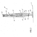
- the umbrella 10 and the frame assembly 12 include a stanchion assembly, generally indicated as 14.
- the stanchion assembly 14 when disposed in an operable position, normally assumes a vertical or at least substantially upstanding position, as shown.
- the lower end 16 of the stanchion assembly 14 is connected to or otherwise associated with a supportive base 18.
- the base 18 typically is disposed on a supporting surface 20, which may be a ground surface, deck, or a variety of other support structures representative of the area for location where the umbrella 10 is used.
- the frame assembly 12 further includes a first or main hub structure 22 movably connected to the stanchion 12 so as to move along at least a portion of the length thereof as the umbrella 10 and frame assembly 12 are disposed between the fully extended position of Figure 1 and the collapsed position of Figure 3.
- a second hub structure 24 is also secured to the stanchion 14 adjacent an upper end thereof as disclosed.
- the second hub 24 functionally differs from the first hub 22 by being connected or attached in a substantially fixed location adjacent the upper portion of the stanchion assembly 14.
- both the first and second hubs 22 and 24 may be rotatable about the central axis of the stanchion assembly 14 if, for example, it is desirable to rotate or reorient the canopy portion of the umbrella. It is also emphasized that while the specific structural features of the first and second hubs 22 and 24 may vary, possible embodiments thereof are substantially equivalent to the hub structures disclosed in U.S. Patent No. 6,314,976 issued to the inventor herein, which patent is incorporated herein in its entirety by reference.
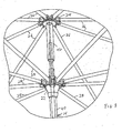
- Additional structural features of the frame assembly 12 include a plurality of ribs 26 having one end pivotally or otherwise movably interconnected to the upper portions of the stanchion assembly 14 such as by being pivotally attached to the second hub 24.
- the ribs 26 may vary in number and serve as the primary structure for the mounting and support of the aforementioned canopy structure.
- the canopy structure is movable with the plurality of ribs 26 as the umbrella 10 and frame assembly 12 are selectively positioned between the expanded position of Figure 1 and the collapsed position of Figure 3.
- FIG. 10 Yet additional structural features of the frame assembly 10 include a plurality of struts 28 which are preferably equal in number to the plurality of ribs 26.
- Each of the struts 28 have an inner end as at 28' pivotally or otherwise movably connected to the first hub 22 and movable therewith along the length of the stanchion 14 as the umbrella 10 and frame assembly 12 are disposed between the expanded and collapsed positions.
- the outer ends 28' of each of the struts 20 are pivotally or otherwise movably connected to a correspondingly position one of the plurality of ribs 26 as schematically represented in Figures 1-3 and shown in more detail in Figures 7 and 8.
- the struts 28 When the struts 28 are disposed in the collapsed position of Figure 3 they substantially surround the exterior of the stanchion 14 and are located on the interior of the plurality of ribs 26, depending downwardly from the hub 24 and/or the upper end of the stanchion.
- distinguishing features of the umbrella 10 as well as the frame assembly 12 include the relatively long, extended length of each of the ribs 26.
- a canopy structure connected to and supported by the ribs 26 when in the expanded position of Figure 1 has a relatively enlarged or significantly increased diameter from that normally found with conventional outdoor, shade umbrellas.
- the shaded area provided by the umbrella 10 can be greatly increased by extending the size of the canopy carried by the frame assembly 10.
- the provision of an enlarged canopy requires the structuring of the plurality of support ribs 26 to have an extended or enlarged length.
- certain problems and/or disadvantages evolve relating to the operation of the umbrella 10 and frame assembly 12, as described previously herein.
- the umbrella 10 and frame assembly 12 is represented in a fully expanded position.
- movement of the ribs 26 to a collapsed or closed position utilizing a conventional stanchion or center, support pole would result in the outer ends 26' of the ribs 26, as well as the periphery of a canopy supported thereon, extending downwardly to a location on the stanchion assembly 14 indicated as 100.
- the path of travel of the outer ends of the ribs 26, utilizing a conventional fixed length stanchion assembly 14, is schematically represented by the directional arrows 102 presented in phantom.
- the ribs 26, being of extended length would be disposed along the length of a conventional, fixed length stanchion to a point very close to the supporting base 18 and/or supporting surface 20.
- This positioning of the ends 26' at the location 100 relative to the supporting surface 20 would result in the inability to place any type of table, seating arrangement or other objects in the immediate vicinity of the supporting base 18 and/or support surface 20.
- tables, chairs, and a variety of other objects are commonly associated with outdoor umbrellas, and in fact, may be specifically structured to surround and/or engage a lower portion of a support pole or stanchion. Provision of such accommodating structures, such as a table, would be impractical for use with a conventional outdoor umbrella having a plurality of ribs of extended length and supporting a canopy of an extended diameter.
- one feature of the present invention is the provision of an umbrella 10, and in particular, a frame assembly 12 having a variable height or longitudinal dimension dependent on whether the umbrella is in the expanded position of Figure 1 or the collapsed position of Figure 3.
- the stanchion assembly 14 of the present invention is specifically structured to have its height, when in an operable position, increased or decreased dependent upon whether the umbrella 10 and frame assembly 12 is in the aforementioned expanded or collapsed positions.
- the stanchion assembly 14 is structured to have its length, or height automatically varied to substantially correspond to the proper or functional height, as set forth above.
- the stanchion assembly 14 includes a first portion 40 which has an elongated configuration and which extends along preferably a majority a length of the stanchion 14 between its opposite ends.
- the first portion of the stanchion 40 includes an at least partially hollow interior and may be generally defined by a tubular construction of the type well known in the umbrella industry.
- the stanchion assembly 14 further comprises a second portion 42 which is coaxially disposed to the first portion 40 and which is separable therefrom as represented in Figures 2, 3, 5, 6 and 8.
- the second portion 42 may comprise a shorter longitudinal dimension than the first portion and defines the upper portion of the stanchion assembly 14 to which a plurality of ribs 26 are connected.
- the plurality ribs 26 move with the second portion 42 and are raised or extended coaxially outwardly from the first portion 40.
- This outward extension or raising of the second portion 42 relative to the first portion 40 serves to increase the height or longitudinal dimension of the stanchion assembly 14 while concurrently raising the plurality of ribs 26 to the position demonstrated in Figure 3, when the umbrella 10 and frame assembly 12 are disposed in the collapsed position.
- the outward extension of the second portion 42 relative to the first portion 40 serves to extend the length of the stanchion 14 and position the plurality of ribs 26. and free ends 26' upwardly, a significantly greater distance from the support surface 20 and support base 18.
- the adjustment assembly preferably comprises a biasing mechanism which, in a most preferred embodiment, comprises a fluid activated biasing structure such as, but not limited to, a pneumatic spring and/or a fluid activated cylinder and piston assembly.
- the biasing mechanism comprises a cylinder and piston assembly including a cylinder 50 fixedly secured on the interior of the stanchion 14 and more specifically on the interior of the first portion 40 of the stanchion assembly 14.
- a piston 52 is cooperatively structured with and movable relative to the cylinder 50 and is disposed, at least partially, on the interior of the second portion 42 of the stanchion assembly 14.
- sleeves 56 and 58 are disposed in concentric, surrounding relation to portions of the cylinder 50 and the piston 52 respectively.
- the cylinder and piston assembly 50 and 52 is activated by air or other fluid. As such, when the umbrella 10 and frame assembly 12 are in the extended position of Figures 1, 4 and 7, the cylinder and piston assembly 50,52 are in a compressed position and as such exert an outwardly directed, separating, biasing force on the second portion 42.
- the biasing force exerted by the cylinder and piston assembly 50,52 serves to separate and extend the second portion 42 outwardly from the first portion 40 of the stanchion assembly 14, as schematically represented by directional arrow 60.
- This serves to extend or lengthen the longitudinal dimension of the stanchion assembly 14 while concurrently raising the plurality of ribs 26 and a canopy structure supported thereon.
- the piston 52 extends outwardly from the cylinder 50 a maximum or predetermined distance so as to separate the second portion 42 from the first portion 40 a predetermined or maximum distance.
- positioning assembly may take the form of a pulley and cable assembly appropriately interconnected to the stanchion assembly 14 and more specifically to the first and second portion 40 and 42 and/or the hubs 22 and 24 mounted thereon.
- the exertion of a pulling force on a positioning cable will result in downward travel of the second portion 42 relative to the first portion 40 against the biasing force exerted thereon by the adjustment assembly 46 until the first and second portions are disposed in contact and/or supporting engagement with one another as clearly demonstrated in Figures 1, 4 and 7.
- the positioning line associated with the aforementioned pulleys may be locked into position by a gripping cleat of the type known in the industry.
- the biasing force of the adjustment assembly 46 will be dominant and serve to raise the second portion 42 from the first portion 40 and thereby extend the longitudinal dimension of the stanchion assembly 14.
- the plurality of supporting ribs 26 and any canopy structure supported thereon will be raised so as to provide adequate spacing between the free ends 26' of the plurality of ribs 26 and the supporting surface 20, as described in detail above.
Landscapes
- Holders For Apparel And Elements Relating To Apparel (AREA)
- Walking Sticks, Umbrellas, And Fans (AREA)
Applications Claiming Priority (2)
| Application Number | Priority Date | Filing Date | Title |
|---|---|---|---|
| US49890703P | 2003-08-29 | 2003-08-29 | |
| US498907P | 2003-08-29 |
Publications (2)
| Publication Number | Publication Date |
|---|---|
| EP1510145A1 true EP1510145A1 (de) | 2005-03-02 |
| EP1510145B1 EP1510145B1 (de) | 2011-05-11 |
Family
ID=34103042
Family Applications (1)
| Application Number | Title | Priority Date | Filing Date |
|---|---|---|---|
| EP04020512A Expired - Lifetime EP1510145B1 (de) | 2003-08-29 | 2004-08-28 | Höhenverstellbare Schirmeinheit |
Country Status (3)
| Country | Link |
|---|---|
| US (1) | US20050045217A1 (de) |
| EP (1) | EP1510145B1 (de) |
| AT (1) | ATE508656T1 (de) |
Cited By (9)
| Publication number | Priority date | Publication date | Assignee | Title |
|---|---|---|---|---|
| US9655416B1 (en) | 2014-05-13 | 2017-05-23 | Dougan H. Clarke | Crank handle positioning assembly for an umbrella |
| US10758015B2 (en) | 2017-04-14 | 2020-09-01 | ZHUN-AN Ma | Tiltable umbrella with removable guide track |
| US11206903B2 (en) | 2019-03-21 | 2021-12-28 | ZHUN-AN Ma | Tilt mechanisms and actuators for umbrellas |
| USD1003592S1 (en) | 2021-08-11 | 2023-11-07 | ZHUN-AN Ma | Umbrella pole grip assembly |
| US12167782B2 (en) | 2020-10-26 | 2024-12-17 | Qingdao Activa Shade Inc. | Umbrella with hub reinforced tilt coupling |
| US12207714B2 (en) | 2021-08-11 | 2025-01-28 | ZHUN-AN Ma | Umbrella pole |
| US12262801B2 (en) | 2021-07-13 | 2025-04-01 | ZHUN-AN Ma | Umbrella assembly with counterweight system |
| US12317977B2 (en) | 2019-03-21 | 2025-06-03 | ZHUN-AN Ma | Tilt mechanisms and actuators for umbrellas |
| US12507772B2 (en) | 2021-11-12 | 2025-12-30 | ZHUN-AN Ma | Umbrella assembly with gas spring |
Families Citing this family (17)
| Publication number | Priority date | Publication date | Assignee | Title |
|---|---|---|---|---|
| CN2737198Y (zh) * | 2004-11-04 | 2005-11-02 | 马准安 | 伞开合装置 |
| WO2008030895A1 (en) * | 2006-09-05 | 2008-03-13 | Oliver Joen-An Ma | Shade structures such as umbrellas |
| FR2913043B1 (fr) * | 2007-02-27 | 2010-11-12 | Vitabri | Structure pliable a developpement et repliement rapide. |
| US7438077B1 (en) * | 2007-08-10 | 2008-10-21 | Wilson Robert J | Sleeve-actuated umbrella |
| JP2010138795A (ja) | 2008-12-11 | 2010-06-24 | Toyota Motor Corp | 内燃機関の制御装置 |
| USD626324S1 (en) | 2009-04-21 | 2010-11-02 | Oliver Joen-An Ma | Umbrella hub |
| US8136541B2 (en) * | 2009-05-14 | 2012-03-20 | Peter John Beaulieu | Umbrella support apparatus |
| US9016295B2 (en) | 2010-02-19 | 2015-04-28 | Robert F. Wise | Patio umbrella with air pump |
| CN202026974U (zh) * | 2011-04-12 | 2011-11-09 | 马准安 | 一种可控型自动开伞装置 |
| USD759955S1 (en) | 2011-12-26 | 2016-06-28 | Oliver Joen-An Ma | Umbrella |
| US9113683B2 (en) | 2012-10-22 | 2015-08-25 | Oliver Joen-An Ma | Umbrella |
| WO2018068492A1 (zh) * | 2016-10-16 | 2018-04-19 | 宁波万汇休闲用品有限公司 | 遮蔽物结构 |
| US10368617B2 (en) | 2016-10-25 | 2019-08-06 | ZHUN-AN Ma | Umbrella assembly set up devices |
| USD822368S1 (en) * | 2016-12-21 | 2018-07-10 | Ching-Chuan You | Two layers umbrella |
| WO2019022693A1 (en) * | 2017-07-22 | 2019-01-31 | Greer Lawrence A | AWNING OF LEISURE |
| US10758016B1 (en) | 2019-11-22 | 2020-09-01 | WeiGang Wang | Adjustable umbrella canopy shade |
| CN112914214B (zh) * | 2021-03-19 | 2025-04-01 | 江苏辉腾休闲用品有限公司 | 一种电气开合的遮阳伞 |
Citations (3)
| Publication number | Priority date | Publication date | Assignee | Title |
|---|---|---|---|---|
| AT362093B (de) | 1975-07-24 | 1981-04-27 | Becher Textil & Stahlbau Gmbh | Standschirm |
| DE3635419A1 (de) | 1985-10-21 | 1987-04-23 | Lughofer Industriemontagen | Standschirm |
| EP1229809A1 (de) | 1999-11-17 | 2002-08-14 | Gaunt, John Peter | Vorrichtung für einen regenschirm |
Family Cites Families (40)
| Publication number | Priority date | Publication date | Assignee | Title |
|---|---|---|---|---|
| US2172549A (en) * | 1939-09-12 | Umbrella | ||
| US1088743A (en) * | 1912-09-11 | 1914-03-03 | John Swinland | Folding umbrella. |
| US1328175A (en) * | 1918-11-07 | 1920-01-13 | Charles W Martin | Umbrella |
| US1411560A (en) * | 1920-09-30 | 1922-04-04 | Beaty Arthur | Umbrella |
| US2336116A (en) * | 1942-05-16 | 1943-12-07 | Emanuel R Morando | Umbrella |
| US2745421A (en) * | 1953-04-16 | 1956-05-15 | Ray A Russell | Umbrella latch and runner combination |
| DE1180903B (de) * | 1958-03-07 | 1964-11-05 | Bremshey & Co | Verkuerzbarer Schirm |
| US3177882A (en) * | 1962-01-08 | 1965-04-13 | Finkel Umbrella Frame Company | Plastic umbrella frames |
| US3213868A (en) * | 1962-02-26 | 1965-10-26 | Robert S Forbes | Foldable fallout shelter |
| US3424180A (en) * | 1965-04-29 | 1969-01-28 | Giancarlo Andolfi | Framework of plastic material for umbrella,beach sunshade or parasols |
| CA1054021A (en) * | 1974-08-31 | 1979-05-08 | Klaus Becher | Standing umbrella |
| US4368749A (en) * | 1978-12-22 | 1983-01-18 | The Shakespeare Company | Wireless umbrella frame |
| US4424824A (en) * | 1982-07-20 | 1984-01-10 | Becher Textil- Und Stahlbau Gmbh | Garden and market umbrella |
| US4766920A (en) * | 1983-04-07 | 1988-08-30 | Christianson Manufacturing Corp. | Internal action improved gas powered umbrella |
| GB8511370D0 (en) * | 1985-05-03 | 1985-06-12 | Robertson M S | Garden/sun umbrellas |
| US4747422A (en) * | 1987-05-07 | 1988-05-31 | Chung Ching Horng | Pneumatic umbrella |
| US4834126A (en) * | 1987-12-11 | 1989-05-30 | Sweet Jr Raymond G | Fiber glass umbrella construction |
| US4832304A (en) * | 1988-05-23 | 1989-05-23 | Tzvika Shahak | Ground-anchoring device particularly for umbrellas |
| US5213122A (en) * | 1988-06-14 | 1993-05-25 | Grady Ii Clyde C | Electric umbrella |
| US4934394A (en) * | 1989-11-28 | 1990-06-19 | Terry Hermanson | Umbrella with hollow staff and spring influenced canopy chords |
| US5020557A (en) * | 1990-07-19 | 1991-06-04 | American Holtzkraft, Inc. | Rotating canopy umbrella |
| US4993445A (en) * | 1990-08-16 | 1991-02-19 | Emanuel Dubinsky | Garden umbrella with solid wooden pole designed to operate with hand crank and pulley system |
| DE9113212U1 (de) * | 1991-02-27 | 1992-04-02 | Becher Textil- & Stahlbau GmbH, 5270 Gummersbach | Schirm, insbesondere Großschirm |
| US5307827A (en) * | 1991-07-22 | 1994-05-03 | Haddad Joseph F | Umbrella |
| US5193566A (en) * | 1992-02-28 | 1993-03-16 | Ocean Import Export Inc. | Umbrella frame |
| US5224505A (en) * | 1992-09-08 | 1993-07-06 | Fu Tai Umbrella Works, Ltd. | Automatic umbrella with upwardly and downwardly thrusted push button |
| US5398709A (en) * | 1994-07-20 | 1995-03-21 | Jong-Chang Huang | Sunshade |
| CN1148950A (zh) * | 1995-04-25 | 1997-05-07 | 迈阿密金属产品股份有限公司 | 伞架 |
| US5640984A (en) * | 1995-09-12 | 1997-06-24 | Dubunsky; Emanuel | Special fold-up umbrella having rib and frame design for easier opening and closing of umbrella, and two canopies designed to stabilize the ribs and vent the air |
| US5725004A (en) * | 1996-05-15 | 1998-03-10 | Moulder; Peter V. | Supported canopy |
| US5715853A (en) * | 1997-01-06 | 1998-02-10 | Asia Umbrella Industries Co., Ltd. | Structure for combining frames of an umbrella |
| US5871024A (en) * | 1997-01-29 | 1999-02-16 | Telescope Casual Furniture Company | Umbrella frame and umbrella for outdoor furniture |
| US5884645A (en) * | 1998-03-03 | 1999-03-23 | Chen; Wu-Hsiung | Collapsible sunshade |
| CH689577A5 (de) * | 1998-03-07 | 1999-06-30 | Steiner Walter | Standschirm. |
| US5836328A (en) * | 1998-03-25 | 1998-11-17 | Lee; Henry | Garden umbrella with upper and lower support ribs |
| TW391201U (en) * | 1998-04-24 | 2000-05-21 | You Ching Chiuan | Improved umbrella rib |
| US6314976B1 (en) * | 1999-06-11 | 2001-11-13 | Tucci Engineering & Design, Inc. | Umbrella frame |
| US6371140B1 (en) * | 2000-04-28 | 2002-04-16 | Dele Atanda | Pneumatic umbrella with shell |
| US6484452B2 (en) * | 2001-03-23 | 2002-11-26 | Yu-Chou Chen | Self-opening/closing umbrella |
| DE50202604D1 (de) * | 2001-07-23 | 2005-05-04 | Glatz Ag | Schirmstock und Schirm mit einem solchen Schirmstock |
-
2004
- 2004-08-28 EP EP04020512A patent/EP1510145B1/de not_active Expired - Lifetime
- 2004-08-28 AT AT04020512T patent/ATE508656T1/de not_active IP Right Cessation
- 2004-08-30 US US10/929,270 patent/US20050045217A1/en not_active Abandoned
Patent Citations (3)
| Publication number | Priority date | Publication date | Assignee | Title |
|---|---|---|---|---|
| AT362093B (de) | 1975-07-24 | 1981-04-27 | Becher Textil & Stahlbau Gmbh | Standschirm |
| DE3635419A1 (de) | 1985-10-21 | 1987-04-23 | Lughofer Industriemontagen | Standschirm |
| EP1229809A1 (de) | 1999-11-17 | 2002-08-14 | Gaunt, John Peter | Vorrichtung für einen regenschirm |
Cited By (11)
| Publication number | Priority date | Publication date | Assignee | Title |
|---|---|---|---|---|
| US9655416B1 (en) | 2014-05-13 | 2017-05-23 | Dougan H. Clarke | Crank handle positioning assembly for an umbrella |
| US10758015B2 (en) | 2017-04-14 | 2020-09-01 | ZHUN-AN Ma | Tiltable umbrella with removable guide track |
| US11388963B2 (en) | 2017-04-14 | 2022-07-19 | ZHUN-AN Ma | Tiltable umbrella with removable guide track |
| US11771186B2 (en) | 2017-04-14 | 2023-10-03 | ZHUN-AN Ma | Tiltable umbrella with removable guide track |
| US11206903B2 (en) | 2019-03-21 | 2021-12-28 | ZHUN-AN Ma | Tilt mechanisms and actuators for umbrellas |
| US12317977B2 (en) | 2019-03-21 | 2025-06-03 | ZHUN-AN Ma | Tilt mechanisms and actuators for umbrellas |
| US12167782B2 (en) | 2020-10-26 | 2024-12-17 | Qingdao Activa Shade Inc. | Umbrella with hub reinforced tilt coupling |
| US12262801B2 (en) | 2021-07-13 | 2025-04-01 | ZHUN-AN Ma | Umbrella assembly with counterweight system |
| USD1003592S1 (en) | 2021-08-11 | 2023-11-07 | ZHUN-AN Ma | Umbrella pole grip assembly |
| US12207714B2 (en) | 2021-08-11 | 2025-01-28 | ZHUN-AN Ma | Umbrella pole |
| US12507772B2 (en) | 2021-11-12 | 2025-12-30 | ZHUN-AN Ma | Umbrella assembly with gas spring |
Also Published As
| Publication number | Publication date |
|---|---|
| US20050045217A1 (en) | 2005-03-03 |
| ATE508656T1 (de) | 2011-05-15 |
| EP1510145B1 (de) | 2011-05-11 |
Similar Documents
| Publication | Publication Date | Title |
|---|---|---|
| EP1510145B1 (de) | Höhenverstellbare Schirmeinheit | |
| US8776816B2 (en) | Portable adjustable shade structure | |
| US7318444B2 (en) | Hub assembly for an umbrella frame | |
| US5937882A (en) | Umbrella with side support for tilting and opening | |
| US5884645A (en) | Collapsible sunshade | |
| US4947884A (en) | Collapsible canopy with auto erect roof support structure | |
| US20020074032A1 (en) | Frame assembly for folding tents | |
| US5845665A (en) | Demountable structure | |
| US11096458B1 (en) | Multi-use umbrella with water filtration and sail functions | |
| AU2011229152A1 (en) | Chair canopy | |
| US11530551B2 (en) | Expandable tent with adjustable height and internal volume | |
| US20090277487A1 (en) | Portable shelter | |
| US20040123890A1 (en) | Collapsible umbrella | |
| KR200267594Y1 (ko) | 천막용 절첩식 차양막 | |
| WO2000014363A1 (en) | Shade stand with swirling type canopy | |
| KR200293682Y1 (ko) | 파라솔 지지장치 | |
| KR101614648B1 (ko) | 멀티 차양 파라솔 | |
| KR20050039173A (ko) | 차양막 절첩구조를 갖는 고정형 대형 파라솔 | |
| CA2471479C (en) | Collapsible umbrella | |
| WO2007018492A1 (en) | Mechanism for opening and closing a canopy | |
| KR20210039074A (ko) | 중앙기둥에 다수개가 회동가능하게 설치된 파라솔 | |
| KR200175249Y1 (ko) | 절첩식 차양을 가진 텐트 | |
| KR200286589Y1 (ko) | 텐트 겸용 기능을 갖는 연장면 파라솔 | |
| CN210086962U (zh) | 一种收折一体化的户外遮阳蓬 | |
| US20080128010A1 (en) | Miniature canopy apparatus for shading head and neck of a sunbather |
Legal Events
| Date | Code | Title | Description |
|---|---|---|---|
| PUAI | Public reference made under article 153(3) epc to a published international application that has entered the european phase |
Free format text: ORIGINAL CODE: 0009012 |
|
| AK | Designated contracting states |
Kind code of ref document: A1 Designated state(s): AT BE BG CH CY CZ DE DK EE ES FI FR GB GR HU IE IT LI LU MC NL PL PT RO SE SI SK TR |
|
| AX | Request for extension of the european patent |
Extension state: AL HR LT LV MK |
|
| 17P | Request for examination filed |
Effective date: 20050902 |
|
| AKX | Designation fees paid |
Designated state(s): AT BE BG CH CY CZ DE DK EE ES FI FR GB GR HU IE IT LI LU MC NL PL PT RO SE SI SK TR |
|
| 17Q | First examination report despatched |
Effective date: 20070307 |
|
| R17C | First examination report despatched (corrected) |
Effective date: 20091007 |
|
| GRAP | Despatch of communication of intention to grant a patent |
Free format text: ORIGINAL CODE: EPIDOSNIGR1 |
|
| RIC1 | Information provided on ipc code assigned before grant |
Ipc: A45B 25/16 20060101AFI20100325BHEP |
|
| GRAS | Grant fee paid |
Free format text: ORIGINAL CODE: EPIDOSNIGR3 |
|
| GRAA | (expected) grant |
Free format text: ORIGINAL CODE: 0009210 |
|
| AK | Designated contracting states |
Kind code of ref document: B1 Designated state(s): AT BE BG CH CY CZ DE DK EE ES FI FR GB GR HU IE IT LI LU MC NL PL PT RO SE SI SK TR |
|
| REG | Reference to a national code |
Ref country code: GB Ref legal event code: FG4D |
|
| REG | Reference to a national code |
Ref country code: CH Ref legal event code: EP |
|
| REG | Reference to a national code |
Ref country code: IE Ref legal event code: FG4D |
|
| REG | Reference to a national code |
Ref country code: NL Ref legal event code: T3 Ref country code: DE Ref legal event code: R096 Ref document number: 602004032598 Country of ref document: DE Effective date: 20110622 |
|
| RAP2 | Party data changed (patent owner data changed or rights of a patent transferred) |
Owner name: TUUCI WORLDWIDE, LLC |
|
| RIN2 | Information on inventor provided after grant (corrected) |
Inventor name: TUUCI WORLDWIDE, LLC |
|
| REG | Reference to a national code |
Ref country code: DE Ref legal event code: R082 Ref document number: 602004032598 Country of ref document: DE |
|
| REG | Reference to a national code |
Ref country code: DE Ref legal event code: R081 Ref document number: 602004032598 Country of ref document: DE Owner name: TUUCI WORLDWIDE, LLC, MIAMI, US Free format text: FORMER OWNER: CLARKE, DOUGAN H., MIAMI, FLA., US Effective date: 20110414 Ref country code: DE Ref legal event code: R081 Ref document number: 602004032598 Country of ref document: DE Owner name: TUUCI WORLDWIDE, LLC, MIAMI, US Free format text: FORMER OWNER: CLARKE, DOUGAN, MIAMI, FLA., US Effective date: 20110826 Ref country code: DE Ref legal event code: R081 Ref document number: 602004032598 Country of ref document: DE Owner name: TUUCI WORLDWIDE, LLC, MIAMI, US Free format text: FORMER OWNER: TUUCI WORLDWIDE, LLC, MIAMI, FLA., US Effective date: 20110831 |
|
| REG | Reference to a national code |
Ref country code: NL Ref legal event code: SD Effective date: 20111018 |
|
| PG25 | Lapsed in a contracting state [announced via postgrant information from national office to epo] |
Ref country code: PT Free format text: LAPSE BECAUSE OF FAILURE TO SUBMIT A TRANSLATION OF THE DESCRIPTION OR TO PAY THE FEE WITHIN THE PRESCRIBED TIME-LIMIT Effective date: 20110912 Ref country code: SE Free format text: LAPSE BECAUSE OF FAILURE TO SUBMIT A TRANSLATION OF THE DESCRIPTION OR TO PAY THE FEE WITHIN THE PRESCRIBED TIME-LIMIT Effective date: 20110511 |
|
| PG25 | Lapsed in a contracting state [announced via postgrant information from national office to epo] |
Ref country code: AT Free format text: LAPSE BECAUSE OF FAILURE TO SUBMIT A TRANSLATION OF THE DESCRIPTION OR TO PAY THE FEE WITHIN THE PRESCRIBED TIME-LIMIT Effective date: 20110511 Ref country code: GR Free format text: LAPSE BECAUSE OF FAILURE TO SUBMIT A TRANSLATION OF THE DESCRIPTION OR TO PAY THE FEE WITHIN THE PRESCRIBED TIME-LIMIT Effective date: 20110812 Ref country code: FI Free format text: LAPSE BECAUSE OF FAILURE TO SUBMIT A TRANSLATION OF THE DESCRIPTION OR TO PAY THE FEE WITHIN THE PRESCRIBED TIME-LIMIT Effective date: 20110511 Ref country code: BE Free format text: LAPSE BECAUSE OF FAILURE TO SUBMIT A TRANSLATION OF THE DESCRIPTION OR TO PAY THE FEE WITHIN THE PRESCRIBED TIME-LIMIT Effective date: 20110511 Ref country code: CY Free format text: LAPSE BECAUSE OF FAILURE TO SUBMIT A TRANSLATION OF THE DESCRIPTION OR TO PAY THE FEE WITHIN THE PRESCRIBED TIME-LIMIT Effective date: 20110511 Ref country code: ES Free format text: LAPSE BECAUSE OF FAILURE TO SUBMIT A TRANSLATION OF THE DESCRIPTION OR TO PAY THE FEE WITHIN THE PRESCRIBED TIME-LIMIT Effective date: 20110822 Ref country code: SI Free format text: LAPSE BECAUSE OF FAILURE TO SUBMIT A TRANSLATION OF THE DESCRIPTION OR TO PAY THE FEE WITHIN THE PRESCRIBED TIME-LIMIT Effective date: 20110511 |
|
| RIN2 | Information on inventor provided after grant (corrected) |
Inventor name: CLARKE, DOUGAN |
|
| PG25 | Lapsed in a contracting state [announced via postgrant information from national office to epo] |
Ref country code: CZ Free format text: LAPSE BECAUSE OF FAILURE TO SUBMIT A TRANSLATION OF THE DESCRIPTION OR TO PAY THE FEE WITHIN THE PRESCRIBED TIME-LIMIT Effective date: 20110511 Ref country code: EE Free format text: LAPSE BECAUSE OF FAILURE TO SUBMIT A TRANSLATION OF THE DESCRIPTION OR TO PAY THE FEE WITHIN THE PRESCRIBED TIME-LIMIT Effective date: 20110511 |
|
| PG25 | Lapsed in a contracting state [announced via postgrant information from national office to epo] |
Ref country code: SK Free format text: LAPSE BECAUSE OF FAILURE TO SUBMIT A TRANSLATION OF THE DESCRIPTION OR TO PAY THE FEE WITHIN THE PRESCRIBED TIME-LIMIT Effective date: 20110511 Ref country code: DK Free format text: LAPSE BECAUSE OF FAILURE TO SUBMIT A TRANSLATION OF THE DESCRIPTION OR TO PAY THE FEE WITHIN THE PRESCRIBED TIME-LIMIT Effective date: 20110511 Ref country code: RO Free format text: LAPSE BECAUSE OF FAILURE TO SUBMIT A TRANSLATION OF THE DESCRIPTION OR TO PAY THE FEE WITHIN THE PRESCRIBED TIME-LIMIT Effective date: 20110511 Ref country code: PL Free format text: LAPSE BECAUSE OF FAILURE TO SUBMIT A TRANSLATION OF THE DESCRIPTION OR TO PAY THE FEE WITHIN THE PRESCRIBED TIME-LIMIT Effective date: 20110511 |
|
| PLBE | No opposition filed within time limit |
Free format text: ORIGINAL CODE: 0009261 |
|
| STAA | Information on the status of an ep patent application or granted ep patent |
Free format text: STATUS: NO OPPOSITION FILED WITHIN TIME LIMIT |
|
| PG25 | Lapsed in a contracting state [announced via postgrant information from national office to epo] |
Ref country code: MC Free format text: LAPSE BECAUSE OF NON-PAYMENT OF DUE FEES Effective date: 20110831 |
|
| REG | Reference to a national code |
Ref country code: CH Ref legal event code: PL |
|
| 26N | No opposition filed |
Effective date: 20120214 |
|
| GBPC | Gb: european patent ceased through non-payment of renewal fee |
Effective date: 20110828 |
|
| PG25 | Lapsed in a contracting state [announced via postgrant information from national office to epo] |
Ref country code: LI Free format text: LAPSE BECAUSE OF NON-PAYMENT OF DUE FEES Effective date: 20110831 Ref country code: CH Free format text: LAPSE BECAUSE OF NON-PAYMENT OF DUE FEES Effective date: 20110831 |
|
| REG | Reference to a national code |
Ref country code: IE Ref legal event code: MM4A |
|
| PG25 | Lapsed in a contracting state [announced via postgrant information from national office to epo] |
Ref country code: IT Free format text: LAPSE BECAUSE OF FAILURE TO SUBMIT A TRANSLATION OF THE DESCRIPTION OR TO PAY THE FEE WITHIN THE PRESCRIBED TIME-LIMIT Effective date: 20110511 |
|
| REG | Reference to a national code |
Ref country code: DE Ref legal event code: R097 Ref document number: 602004032598 Country of ref document: DE Effective date: 20120214 |
|
| PG25 | Lapsed in a contracting state [announced via postgrant information from national office to epo] |
Ref country code: IE Free format text: LAPSE BECAUSE OF NON-PAYMENT OF DUE FEES Effective date: 20110828 |
|
| PG25 | Lapsed in a contracting state [announced via postgrant information from national office to epo] |
Ref country code: GB Free format text: LAPSE BECAUSE OF NON-PAYMENT OF DUE FEES Effective date: 20110828 |
|
| PG25 | Lapsed in a contracting state [announced via postgrant information from national office to epo] |
Ref country code: LU Free format text: LAPSE BECAUSE OF NON-PAYMENT OF DUE FEES Effective date: 20110828 |
|
| PG25 | Lapsed in a contracting state [announced via postgrant information from national office to epo] |
Ref country code: BG Free format text: LAPSE BECAUSE OF FAILURE TO SUBMIT A TRANSLATION OF THE DESCRIPTION OR TO PAY THE FEE WITHIN THE PRESCRIBED TIME-LIMIT Effective date: 20110811 |
|
| PG25 | Lapsed in a contracting state [announced via postgrant information from national office to epo] |
Ref country code: TR Free format text: LAPSE BECAUSE OF FAILURE TO SUBMIT A TRANSLATION OF THE DESCRIPTION OR TO PAY THE FEE WITHIN THE PRESCRIBED TIME-LIMIT Effective date: 20110511 |
|
| PG25 | Lapsed in a contracting state [announced via postgrant information from national office to epo] |
Ref country code: HU Free format text: LAPSE BECAUSE OF FAILURE TO SUBMIT A TRANSLATION OF THE DESCRIPTION OR TO PAY THE FEE WITHIN THE PRESCRIBED TIME-LIMIT Effective date: 20110511 |
|
| REG | Reference to a national code |
Ref country code: FR Ref legal event code: PLFP Year of fee payment: 13 |
|
| REG | Reference to a national code |
Ref country code: FR Ref legal event code: PLFP Year of fee payment: 14 |
|
| REG | Reference to a national code |
Ref country code: FR Ref legal event code: PLFP Year of fee payment: 15 |
|
| PGFP | Annual fee paid to national office [announced via postgrant information from national office to epo] |
Ref country code: NL Payment date: 20230828 Year of fee payment: 20 |
|
| PGFP | Annual fee paid to national office [announced via postgrant information from national office to epo] |
Ref country code: FR Payment date: 20230828 Year of fee payment: 20 Ref country code: DE Payment date: 20230829 Year of fee payment: 20 |
|
| REG | Reference to a national code |
Ref country code: DE Ref legal event code: R071 Ref document number: 602004032598 Country of ref document: DE Ref country code: NL Ref legal event code: MK Effective date: 20240827 |