EP1510103B1 - Headset - Google Patents
Headset Download PDFInfo
- Publication number
- EP1510103B1 EP1510103B1 EP03724773A EP03724773A EP1510103B1 EP 1510103 B1 EP1510103 B1 EP 1510103B1 EP 03724773 A EP03724773 A EP 03724773A EP 03724773 A EP03724773 A EP 03724773A EP 1510103 B1 EP1510103 B1 EP 1510103B1
- Authority
- EP
- European Patent Office
- Prior art keywords
- loudspeaker
- chinstrap
- receiver
- ear
- receiver according
- Prior art date
- Legal status (The legal status is an assumption and is not a legal conclusion. Google has not performed a legal analysis and makes no representation as to the accuracy of the status listed.)
- Expired - Lifetime
Links
- 230000005540 biological transmission Effects 0.000 claims abstract description 13
- 230000008878 coupling Effects 0.000 claims description 15
- 238000010168 coupling process Methods 0.000 claims description 15
- 238000005859 coupling reaction Methods 0.000 claims description 15
- 230000001419 dependent effect Effects 0.000 claims description 4
- 238000004321 preservation Methods 0.000 claims 1
- 210000000883 ear external Anatomy 0.000 abstract 1
- 230000001131 transforming effect Effects 0.000 abstract 1
- 210000000613 ear canal Anatomy 0.000 description 13
- 210000003128 head Anatomy 0.000 description 10
- 230000008859 change Effects 0.000 description 7
- 230000036544 posture Effects 0.000 description 4
- 238000011161 development Methods 0.000 description 3
- 230000018109 developmental process Effects 0.000 description 3
- 230000007246 mechanism Effects 0.000 description 3
- 230000005236 sound signal Effects 0.000 description 2
- 230000009471 action Effects 0.000 description 1
- 230000002411 adverse Effects 0.000 description 1
- 230000008901 benefit Effects 0.000 description 1
- 238000010276 construction Methods 0.000 description 1
- 230000001186 cumulative effect Effects 0.000 description 1
- 238000005553 drilling Methods 0.000 description 1
- 230000000694 effects Effects 0.000 description 1
- 238000005516 engineering process Methods 0.000 description 1
- 230000006870 function Effects 0.000 description 1
- 230000006872 improvement Effects 0.000 description 1
- 230000002452 interceptive effect Effects 0.000 description 1
- 238000000034 method Methods 0.000 description 1
- 230000009467 reduction Effects 0.000 description 1
- 230000004044 response Effects 0.000 description 1
Images


Classifications
-
- H—ELECTRICITY
- H04—ELECTRIC COMMUNICATION TECHNIQUE
- H04R—LOUDSPEAKERS, MICROPHONES, GRAMOPHONE PICK-UPS OR LIKE ACOUSTIC ELECTROMECHANICAL TRANSDUCERS; DEAF-AID SETS; PUBLIC ADDRESS SYSTEMS
- H04R1/00—Details of transducers, loudspeakers or microphones
- H04R1/10—Earpieces; Attachments therefor ; Earphones; Monophonic headphones
- H04R1/1058—Manufacture or assembly
- H04R1/1066—Constructional aspects of the interconnection between earpiece and earpiece support
-
- H—ELECTRICITY
- H04—ELECTRIC COMMUNICATION TECHNIQUE
- H04R—LOUDSPEAKERS, MICROPHONES, GRAMOPHONE PICK-UPS OR LIKE ACOUSTIC ELECTROMECHANICAL TRANSDUCERS; DEAF-AID SETS; PUBLIC ADDRESS SYSTEMS
- H04R1/00—Details of transducers, loudspeakers or microphones
- H04R1/10—Earpieces; Attachments therefor ; Earphones; Monophonic headphones
- H04R1/1016—Earpieces of the intra-aural type
-
- H—ELECTRICITY
- H04—ELECTRIC COMMUNICATION TECHNIQUE
- H04R—LOUDSPEAKERS, MICROPHONES, GRAMOPHONE PICK-UPS OR LIKE ACOUSTIC ELECTROMECHANICAL TRANSDUCERS; DEAF-AID SETS; PUBLIC ADDRESS SYSTEMS
- H04R5/00—Stereophonic arrangements
- H04R5/033—Headphones for stereophonic communication
- H04R5/0335—Earpiece support, e.g. headbands or neckrests
Definitions
- the present invention relates to a chin guard receiver according to the preamble of claim 1.
- an infrared headphone has become known, which consists of two connected via a chin guard Wiedergabewandiem, from an infrared signals receiving and convert into audio signals in the electrical circuit and two microphones with downstream Mikrofonverstäkern.
- the circuit of this infrared headphone is held so that the Bachabevem either the respectively derived from the infrared circuit and the microphone amplifiers signals or singly or in combination are supplied.
- the microphones are arranged at a distance from each other on the chin guard in such a way that they are symmetrical to the media plane of the user's head, the signals derived from the microphones being supplied in opposite proportion to the respectively other microphone amplifier in opposite phase.
- This infrared headphones is usually in operative connection with a transmitter, which converts the emitted sound signals, for example from a television or from a hi-fi system, into invisible infrared rays, and radiates them into the room, where they receive from the infrared headphones become, with which a wireless infrared sound transmission can be provided. It makes sense that such a transmitter at the same time charging station for the infrared receiver and for at least a rechargeable battery that is used when charged to operate the infrared headset.
- the publication WO 95/35011 A discloses an infrared earphone designed as a chin strap receiver.
- This infrared headphones consists essentially of a basic housing, two mounting brackets, each with a small speaker arranged end.
- the two support brackets are mounted in the base housing, wherein those in each case in conjunction with a force acting in the region of the bearing spring element can be spread, so on these spring elements a pleasant ear attachment of the miniature speaker can be accomplished.
- the in and Ausser istsish is made in this headphone by means of a hand-operated switch.
- the pamphlets GB 2 304 488 A and FR 2 280 283 A also disclose wireless headphones, in which the expandable designed as a headband temple ends also allow flexible ear attachment and in which an on / off switch is integrated, the on / off operation is dependent brackets, which makes manual operation of the switch is unnecessary.
- the DE 196 45 307 A1 discloses a sound amplifier for a headphone, in particular for a chin guard receiver, which essentially provides a base housing, two individually guided, each hinged about a hinge joint against the base housing tiltably mounted mounting bracket and one end of the mounting brackets arranged small speaker.
- WO 00/08893 A1 is to remove a headphone, at the two ends of each bracket a loudspeaker unit is attached.
- the speaker units are pivotally mounted to the support bracket ends by means of a pivoting mechanism not further disclosed in the document.
- the invention aims to remedy this situation.
- the invention as characterized in the claims, the object is based on a chin guard receiver of the type mentioned to take those measures that can overcome the above-mentioned disadvantages by correcting any change in the head position when wearing the headset by a dispositive corrective becomes.
- the miniature loudspeakers or, in the case of conventional chin strap receivers, the enclosing attachment parts be formed into the ear canal in such a way that the relevant parts in the area of the auditory canal can be easily rotated and adapted to the respective head and posture of the user, or they depending on the carrying of the chin guard receiver by the
- a Eisensaner Kinnbügelempffiter is characterized by the features of claim 1.
- the essential advantage of the invention lies in the fact that this training can be implemented to any kind of small speakers, and that thus a maximum of sound transmission quality is achieved.
- the chin guard receiver 100 is shown in use on users Such a chin-strap receiver 100 is in the document WO 00/08894 described in detail, this document forms an integral part of the present description.
- this chin-latch receiver 100 is a device which is used to record drister signals, such as infrared or radio signals, and is designed to convert them into a sound transmission in the audible range.
- this Kinnbügelempftuler 100 consists of a base housing 101, two support brackets 102, 103 each arranged at the end small speakers 300, 400.
- the two support bracket 102, 103 are mounted in the base housing 101 and resiliently spreadable in at least one plane.
- These mounting brackets 102, 103 are in operative connection with at least one in the lever action area of this level accommodated switch, such that this switch at a certain bearing-dependent expansion position of the support bracket 102, 103 turns on the receiver circuit, whereby an advantageous automatic switching on and off of the receiver in response to wearing the chin guard receiver.
- a sound management which sound management automatically intervenes depending on the solitary sound transmission quality at an interfering reception circuitry, such that is either worked on an improvement in sound quality, or falls below a certain Tongüte automatically the Uebartragung off and this transmission at Restoration of the minimum requirements for the sound quality automatically switches on again.
- the shading sound management further includes that a switch from mono to stereo reception, or vice versa, is always switchable.
- the features described here can of course be transferred to conventional headphones with built-in receiver. All of the above-mentioned functions concerning sound management are cumulative with each other as an alternative to each other.
- Fig. 2 shows a Hörempftuler 200, which is designed as a stethoscope, in which case the sound transmission can also be accomplished by means of a cable.
- the comments below are based essentially on the comments Fig. 1 directed.
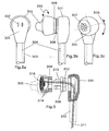
- FIG. 3 shows the embodiment of a miniature speaker 300, which is designed so that it closes the ear canal plug or Pfropfenschlichst.
- this miniature speaker 300 is on the FIGS. 3a-3c, 5 directed.
- Fig. 4 shows the embodiment of a lenticular loudspeaker body (405), which is performed parallel or quasi-parallel to the ear canal, the auditory canal therefore only partially completes and thus leaves open.
- this lens-shaped small speaker 400 is on the Figs. 4a-4c and 6-8 directed.
- Fig. 3a-3c show the miniature speaker 300 in different views.
- a miniature loudspeaker 300 consists of a base body 301, which is provided on the output side with acoustic sound openings 307 and on the back side with further acoustic openings 302.
- the main body 301 is connected to the mounting bracket 303, which is only partially visible here.
- the miniature loudspeaker 300 has a plug-shaped loudspeaker body 305 which closes off the auditory canal.
- a coupling member 308 is arranged with a connected sleeve 309, wherein the connection of the last-mentioned parts 308 and 309 with respect to the base body 301 and speaker body 305 is designed so that between the latter 305 and the base body 301, a free rotation 306 of a certain angle is possible.
- any change in the head position can be absorbed by the user, such that the loudspeaker body 305 of the respective miniature loudspeaker 300 fixed in the auditory canal is not exposed to any rotational pressure due to its rotatability relative to the main body 301, thereby maximizing the wearing comfort combined with a maximum of sound transmission quality is reached, since in the latter effect a position-dependent acoustic changes in the sound transmission is eliminated.
- Fig. 5 shows in a sectional plane the structure of such a small speaker after the Fig. 3a-3c .
- the coupling part 308 takes over the connection between the base body 301 and the loudspeaker body 305, this in turn being supplemented with a bushing 309, which on the one hand takes over the bearing of the loudspeaker 310, and on the other hand as an abutment and rotational locking 314 of the latching points belonging to the coupling 308 313.
- Fig. 6-8 show the structural design of the small speaker 400 according Fig. 4a-4c
- the acoustic openings 402 and the acoustic sound openings 407 are arranged in the large areas of the lenticular loudspeaker body 405.
- the main difference of this miniature loudspeaker 400 from the previous 300 is that it is an insert parallel or quasi-parallel to the ear canal with a partially open auditory canal.
- this miniature speaker 400 which relates to the rotation 406, is largely the same as in the previous miniature speaker (300), ie, here by means of a coupling part 411 with a Einklinkteil (analog 313) achieved that rotation, which serves the described final purpose
- the outer geometry of this small speaker 400 is of course its own and it goes out of the Fig. 6-8 unmistakable.
- a snap mechanism 412/413 ensures that the cover portion 409 can be latched to give a compact rounded geometry, which is very important for proper support of the speaker body in the ear.
- the remaining parts of this mini speaker 400 have the same functionality as the previous mini speaker (300).
- Bel headphones in which the fitting surrounds the entire auricle, also reveals a rotation not shown in the drawing provide the same criteria already described, so that the or the support bracket can then be worn arbitrarily on the head.
- connection lines 311, 414 a connection by means of Schteifringuttone can be provided for sound transmission in the region of the rotatable parts, which then ensure the electrical connection between the portable loudspeaker bodies 305, 405 and the respective basic bodies 301, 401.
Abstract
Description
Die vorliegende Erfindung betrifft einen Kinnbügelempfänger gemäss Oberbegriff des Anspruchs 1.The present invention relates to a chin guard receiver according to the preamble of
Aus
Dieser Infrarot-Kopfhörer steht dabei üblicherweise in Wirkverbindung mit einem Sender, der die emittierten Tonsignale, beispielsweise aus einem Fernseher oder aus einer HiFi-Anlage, in unsichtbare Infrarot-Strahlen umwandelt, und diese in den Raum abstrahlt, wo sie vom Infrarot-Kopfhörer empfangen werden, womit eine drahtlose Infrarot-Tonübertragung bereitgestellt werden kann. Sinnvollerweise ist ein solcher Sender zugleich Ladestation für den Infrarot-Empfänger und für mindestens einen Akku-Einsatz, der im aufgeladenen Zustand zum Betrieb des Infrarot-Kopfhörers eingesetzt wird.This infrared headphones is usually in operative connection with a transmitter, which converts the emitted sound signals, for example from a television or from a hi-fi system, into invisible infrared rays, and radiates them into the room, where they receive from the infrared headphones become, with which a wireless infrared sound transmission can be provided. It makes sense that such a transmitter at the same time charging station for the infrared receiver and for at least a rechargeable battery that is used when charged to operate the infrared headset.
Die Druckschrift
Die Druckschriften
Alle die genannten zum Stand der Technik gehörenden Kopfhörer haben eines gemeinsam, dass die Kleinlautsprecher, auch Lautsprecher genannt, und deren Gehäuse fest mit den Tragbügeln des Kinnbügelsystems verbunden sind. Dabei trägt der Benutzer solcher Systeme den Kopfhörer vornehmlich jeweils in leicht vorgebeugter oder zurücklehnender Haltung, dergestalt, dass diese Systeme, unabhängig davon, ob der Benutzer stehend, sitzend oder gehend, aufgrund ihres Eigengewichts senkrecht nach unten hängen. Indessen, bei jeder noch so minimalen Aenderung der Position des Kopfes verändert sich die Lage der Kleinlautsprecher in den Ohrmuscheln gegenüber dem Gehörkanal, was zu folgenden Unzulänglichkeiten führt:
- a) Hierbei passen sich die Kleinlautsprecher jedesmal, auch bei jeder noch so kleinen Veränderung, der neuen Position an, was zu einer Reibung in den Ohrmuschein und im Gehörgang kommt, was der Benutzer wiederum als höchst unangenehm empfindet.
- b) Insbesondere bei Kleinlautsprechern, die den Gehörgang stöpsel- oder pfropfenähnlich verschliessen, verändert sich deren Lage zum Gehörgang. Dadurch verändern sich auch die urspranglichen akustischen Eigenschaften zum menschlichen Ohrsystem. Dies führt insbesondere bei Benutzern mit Hörver lusten in bestimmten Frequenzbereichen zu akustischen Veränderungen, welche in den meisten Fällen das optimale Hörempfinden beeinträchtigen, abgesehen davon, dass sich durch die unterschiedlichen Hörerdrücke zwischen dem einen zum anderen Ohr nachteilige Veränderungen der stereophonen Balance einstellen, welche dem Hörempfinden herabmindern.
- c) Aber auch bei Kleinlautsprechern, die parallel oder quasi-parallel zum Gehörgang geführt werden und den Gehörgang nur teilweise abschliessen, bewirkt jede neue Kopfposition eine Lageveranderung der Kleinlautsprecher zum Ohrmuschel/Gehörgang, was sich auf dem Tragkonfort negativ auswirkt und zu unangenehmen anfühlenden Lagen führt sowie das Hörempfinden negativ beeinflusst.
- a) Here, the small speakers adapt each time, even with any small change, the new position, resulting in a friction in the pinna and in the ear canal, which in turn feels the user to be extremely unpleasant.
- b) Especially for small speakers, the plugging or plug-like close the ear canal, their position changes to the ear canal. As a result, the urspranglichen acoustic properties to the human ear system change. This leads in particular in users with Hörver losses in certain frequency ranges to acoustic changes, which affect the optimal hearing in most cases, except that adjust by the different hearing pressures between one to the other ear adverse changes in stereophonic balance, which the hearing diminish.
- c) But even with small speakers, which are performed parallel or quasi-parallel to the ear canal and the auditory canal only partially complete, each new head position causes a change in position of the small speaker to the pinna / ear canal, which has a negative impact on the Tragkonfort and leads to unpleasant and sensitive layers as well as the sense of hearing negatively influenced.
Die
Der
Hier will die Erfindung Abhilfe schaffen. Der Erfindung, wie sie in den Ansprüchen gekennzeichnet ist, liegt die Aufgabe zugrunde, bei einem Kinnbügelempfänger der eingangs genannten Art jene Massnahmen zu ergreifen, welche die obengenannten Nachteile zu beheben vermag, indem jede Veränderung der Kopfposition beim Tragen des Kopfhörers durch ein Dispositiv korrigierend aufgefangen wird.The invention aims to remedy this situation. The invention, as characterized in the claims, the object is based on a chin guard receiver of the type mentioned to take those measures that can overcome the above-mentioned disadvantages by correcting any change in the head position when wearing the headset by a dispositive corrective becomes.
Es wird vorgeschlagen, die Kleinlautsprecher oder bei konventionellen Kinnbügelempfänger die umschliewenden Ansetzteile zu den Ohrmuschein so weiter zu bilden, dass die relevante Teile im Bereich des Hörganges sich leicht drehbar ausgestaltet werden und sie sich der jeweiligen Kopf- und Körperhaltung beim Benutzer anpassen können, oder sie sich je nach Tragweise des Kinnbügelempfängers durch denIt is proposed that the miniature loudspeakers or, in the case of conventional chin strap receivers, the enclosing attachment parts be formed into the ear canal in such a way that the relevant parts in the area of the auditory canal can be easily rotated and adapted to the respective head and posture of the user, or they depending on the carrying of the chin guard receiver by the
Benutzer anpassen können, ohne dadurch im geringsten der ursprünglichen Lage im Gehörgang oder hinsichtlich der Umschliessung der Ohrmuschel verlustig zu gehen.Users can adjust without losing the slightest of the original position in the ear canal or with respect to the enclosure of the auricle.
Ein Lösungsgemäßer Kinnbügelempfänger zeichnet sich durch die Merkmale des Anspruches 1 aus. Der wesentliche Vorteil der Erfindung ist darin zu sehen, dass sich diese Weiberbildung zu jeder Art von Kleinlautsprechern Implementieren lässt, und dass damit ein Höchstmaß an Tonübertragungsqualität erreicht wird.A Lösungsaner Kinnbügelempfänger is characterized by the features of
Des weiteren wird durch die erfindungsgemässe Weiterbildung erreicht, dass sich damit eine Maximierung des Tragkonforts erzielen lässt, was die Akzeptanz für solche Systeme, nämlich Kinnbügelempfänger, Kopfhörer, etc., seien sie kabelgebunden oder kabellos nur steigern kann, wobei die kabellose Variante auf Infrarot, Funkfrequenz, etc., ausgelegt sein kann.Furthermore, it is achieved by the development according to the invention that it is thus possible to maximize the wearing comfort, which can only increase the acceptance of such systems, namely, chin-strap receivers, headphones, etc., whether wired or wireless, the wireless variant being based on infrared, Radio frequency, etc., can be designed.
Vorteilhafte und zweckmässige Weiterbildungen der erfindungsgemässen Aufgabenlösung sind in den weiteren Ansprüche gekennzeichnetAdvantageous and expedient developments of the task solution according to the invention are characterized in the further claims
Im folgenden werden anhand der Zeichnungen Ausführungsbeispiele der Erfindung näher erläutert. Alle für das unmittelbare Verständnis der Erfindung unwesentlichen Merkmale sind fortgelassen worden. Gleiche Merkmale sind in den verschiedenen Figuren mit den gleichen Bezugszeichen versehen.In the following embodiments of the invention will be explained in more detail with reference to the drawings. All features that are immaterial to the instant understanding of the invention have been omitted. Identical features are provided in the various figures with the same reference numerals.
Es zeigt
- Fig. 1
- einen Hörempfänger als Kinnbügel tragend,
- Fig. 2
- einen Hörempfänger als Stethosklip tragend,
- Fig. 3
- einen Kleinlautsprecher Gehörgang abschliessend,
- Fig. 3a-3c
- verschiedene Ansichten des Memtautsprechers gemäss
Fig. 3 , - Fig. 4
- einen Kleinlautsprecher parallel oder quasi parallel zum Gehörgang,
- Fig. 4a-4c
- verschiedene Ansichten des Kleinlautsprechers gemäss
Fig. 4 , - Fig. 5
- einen Kleinlautsprecher gemäss
Fig. 3 mit einer drehbaren Ankopplung, - Flg. 6
- eine drehbare Ankoppelung des Kleinlautsprechers gemäss
Fig. 4 in seitlicher Ansicht, - Fig. 7
- die Grundansicht der ohrseitigen Partie des Kleinlautsprechers gemäss
Fig. 4 und - Fig. 8
- die drehbare Ankopplung des Klelnlaufsprechers gemäss
Fig. 4 in Oberaufsicht.
- Fig. 1
- wearing a listener as a chin guard,
- Fig. 2
- wearing a listener as a stethoscope
- Fig. 3
- completing a miniature speaker ear canal,
- Fig. 3a-3c
- different views of Memtautsprechers according
Fig. 3 . - Fig. 4
- a miniature loudspeaker parallel or quasi parallel to the auditory canal,
- Fig. 4a-4c
- different views of the small loudspeaker according to
Fig. 4 . - Fig. 5
- a small speaker according to
Fig. 3 with a rotatable coupling, - Flg. 6
- a rotatable coupling of the small speaker according to
Fig. 4 in lateral view, - Fig. 7
- the basic view of the ear-side lot of the small speaker according to
Fig. 4 and - Fig. 8
- the rotatable coupling of the Klelnlaufsprechers according
Fig. 4 in overall supervision.
Der Kinnbügelempfänger 100 gemäss
Die
Bel Kopfhörern, bei welchen das Passstück die ganze Ohrmuschel umschliesst, lässt sich ebenfalls eine in der Zeichnung nicht näher gezeigte Drehbarkeit nach denselben bereits beschriebenen Kriterien vorsehen, so dass der oder die Tragbügel dann beliebig am Kopf getragen werden können.Bel headphones, in which the fitting surrounds the entire auricle, also reveals a rotation not shown in the drawing provide the same criteria already described, so that the or the support bracket can then be worn arbitrarily on the head.
Anstelle der beschriebenen elektrischen Anschlussleitungen 311, 414 lässt sich zur Tonübertragung im Bereich der drehbaren Teile eine Verbindung mittels Schteifringkontakte vorsehen, welche dann die elektrische Verbindung zwischen den bewegilchen Lautsprecherkörpern 305, 405 und den jeweiligen Grundkörpern 301, 401 sicherstellen.Instead of the described
Durch den Einbau einer in der Zeichnung nicht näher gezeigten Torsionsfeder am geeigneten Ort wird sichergesteilt, dass bei Nichtmehrbenutzung des Kopfhörers die Lage der Lautsprecherkörper 305, 405 gegenüber den Grundkörpern 301, 401 jene ursprüngliche Ruhesteilung wieder einnimmtBy installing a torsion spring not shown in the drawing at the appropriate location is sichergesteilt that when not using the headphone, the position of the
- 100100
- KinnbügelempfängerChin receiver
- 101101
- GrundgehäuseHeaders
- 102102
- Tragbügel allgemeinMounting bracket general
- 103103
- Tragbügel allgemeinMounting bracket general
- 200200
- StethosklipStethosklip
- 300300
- KleinlautsprecherSmall speaker
- 301301
- Grundkörperbody
- 302302
- Akustische OeffnungenAcoustic openings
- 303303
- Endteil des TragbügelsEnd part of the support bracket
- 304304
- KabelkanalCabel Canal
- 305305
- Pfropfenförmiger LautsprecherkörperPlug-shaped speaker body
- 306306
- Drehwinkelangle of rotation
- 307307
- Akustische TonöffnungenAcoustic sound openings
- 308308
- Kupplungsteilcoupling part
- 309309
- Büchserifle
- 310310
- Lautsprecherspeaker
- 311311
- Elektrische AnschlussleitungElectrical connection cable
- 312312
- Bohrungdrilling
- 313313
- Einklinkteillatching unit
- 314314
- Anschlag/DreharretlerungStop / Dreharretlerung
- 400400
- KleinlautsprecherSmall speaker
- 401401
- Grundkörperbody
- 402402
- Akustische OeffnungenAcoustic openings
- 403403
- Endteil des TragbügelsEnd part of the support bracket
- 404404
- KabelkanalCabel Canal
- 405405
- Linsenförmiger LautsprecherkörperLens-shaped speaker body
- 406406
- Drehwinkelangle of rotation
- 407407
- Akustische TonöffnungenAcoustic sound openings
- 408408
- Verbindungsteilconnecting part
- 409409
- Abdeckungsteilcover part
- 410410
- Lautsprecherspeaker
- 411411
- Kupplungsteilcoupling part
- 412/413412/413
- Schnappmechanismussnap mechanism
- 414414
- Elektrische AnachlussleitungElectrical connection line
Claims (6)
- Chinstrap receiver for picking up infrared, radio signals and converting said signals into an audio transmission in the audible range, which chinstrap receiver essentially comprises a basic housing (101), a cohesive support strap or two individually routed support straps (102, 103) with a respective small loudspeaker arranged at the end, wherein each small loudspeaker has a basic body (301), a coupling portion (308), a loudspeaker (310), a socket (309) and an ear-end loudspeaker body (305), wherein the loudspeaker body is located in the auditory canal or encloses the entire auricle and is rotationally mounted opposite each support strap (102, 103) or a connection portion for each support strap, characterized in that the coupling portion (308) is permanently connected to the basic body (301) and the coupling portion is operatively connected to the socket (309) and hence ensures that the loudspeaker body can rotate freely relative to the basic body.
- Chinstrap receiver according to Claim 1, characterized in that the ear-end loudspeaker body (305) is in the shape of a plug.
- Chinstrap receiver according to Claim 1, characterized in that the ear-end loudspeaker body (405) is in lenticular form.
- Chinstrap receiver according to Claim 1, characterized in that the support straps (102, 103) are mounted in the basic housing (101) and can be spread in at least one plane, in that the support straps are operatively connected to at least one switch accommodated in the lever active area of said plane, and in that said switch switches on the receiving loop when the support straps are in a particular load-dependent spread position, in that the chinstrap receiver has circuit-based audio management, which audio management ensures and/or guarantees the preservation of a minimum prescribed audio quality and/or changeover from mono to stereo reception, and in that a drop below a particular audio quality prompts the transmission to be automatically switched off, and said transmission is automatically switched on again when the audio quality is restored.
- Chinstrap receiver according to Claim 1, characterized in that the electrical connection between a signal receiver associated with the basic housing and the loudspeaker bodies (305, 405) is made by a connecting line (311, 414) which is routed internally through the support straps (102, 103) and the small loudspeakers (300, 400).
- Chinstrap receiver according to Claim 1, characterized in that the electrical connection in the region of the rotatable portions (305, 405/301, 401) is made by means of slipring contacts.
Applications Claiming Priority (3)
| Application Number | Priority Date | Filing Date | Title |
|---|---|---|---|
| CH934022002 | 2002-06-04 | ||
| CH9342002 | 2002-06-04 | ||
| PCT/CH2003/000350 WO2003103335A1 (en) | 2002-06-04 | 2003-06-02 | Headset |
Publications (2)
| Publication Number | Publication Date |
|---|---|
| EP1510103A1 EP1510103A1 (en) | 2005-03-02 |
| EP1510103B1 true EP1510103B1 (en) | 2011-03-30 |
Family
ID=29589393
Family Applications (1)
| Application Number | Title | Priority Date | Filing Date |
|---|---|---|---|
| EP03724773A Expired - Lifetime EP1510103B1 (en) | 2002-06-04 | 2003-06-02 | Headset |
Country Status (6)
| Country | Link |
|---|---|
| US (1) | US7356156B2 (en) |
| EP (1) | EP1510103B1 (en) |
| AT (1) | ATE504166T1 (en) |
| AU (1) | AU2003229240A1 (en) |
| DE (1) | DE50313583D1 (en) |
| WO (1) | WO2003103335A1 (en) |
Cited By (1)
| Publication number | Priority date | Publication date | Assignee | Title |
|---|---|---|---|---|
| WO2019127173A1 (en) * | 2017-12-28 | 2019-07-04 | 歌尔科技有限公司 | Virtual reality head-mounted device |
Families Citing this family (25)
| Publication number | Priority date | Publication date | Assignee | Title |
|---|---|---|---|---|
| GB2417166A (en) * | 2004-08-12 | 2006-02-15 | Simon Richard Daniel | A headset assembly |
| EP1705949A1 (en) * | 2005-03-22 | 2006-09-27 | Sony Ericsson Mobile Communications AB | An electroacoustic device |
| US20060239447A1 (en) * | 2005-04-26 | 2006-10-26 | Shure Acquisition Holdings, Inc. | Earphone with selectable cable positioning |
| US7697709B2 (en) * | 2005-09-26 | 2010-04-13 | Cyber Group Usa, Inc. | Sound direction/stereo 3D adjustable earphone |
| US8092396B2 (en) * | 2005-10-20 | 2012-01-10 | Merat Bagha | Electronic auscultation device |
| JP4709017B2 (en) * | 2006-01-12 | 2011-06-22 | ソニー株式会社 | Earphone device |
| US20080170738A1 (en) * | 2007-01-16 | 2008-07-17 | Sony Ericsson Mobile Communications Ab | Adjustable earphones for portable devices |
| US8265324B2 (en) * | 2007-01-26 | 2012-09-11 | Virgin Mobile Usa, Llc | Stereo headset with integrated earpiece mount |
| CN201039439Y (en) * | 2007-04-17 | 2008-03-19 | 郁志曰 | An angle-adjustable earphone device |
| US20090123016A1 (en) * | 2007-11-09 | 2009-05-14 | Mark Joseph Rise | Headpiece with releasably engaged earbud securement system |
| US20090285434A1 (en) * | 2008-05-13 | 2009-11-19 | Jason Martin Williams | Earhook and earbud headset |
| JP4333885B1 (en) * | 2008-09-26 | 2009-09-16 | フォスター電機株式会社 | earphone |
| CN101729955B (en) * | 2008-10-15 | 2014-03-26 | 诸爱道 | Safe insert earphone |
| KR100999321B1 (en) * | 2008-11-18 | 2010-12-08 | 필스전자 주식회사 | Tilting earphone |
| US8160287B2 (en) * | 2009-05-22 | 2012-04-17 | Vocollect, Inc. | Headset with adjustable headband |
| US8515103B2 (en) * | 2009-12-29 | 2013-08-20 | Cyber Group USA Inc. | 3D stereo earphone with multiple speakers |
| US8467561B2 (en) * | 2010-06-14 | 2013-06-18 | Merry Electronics Co., Ltd. | Earphone device with a function of sound quality regulation and regulating method thereof |
| US8401218B2 (en) * | 2010-07-29 | 2013-03-19 | Microsoft Corporation | Adjustable earphone and earphone set |
| US9712905B2 (en) * | 2012-06-20 | 2017-07-18 | Apple Inc. | Headsets with non-occluding earbuds |
| US8971561B2 (en) | 2012-06-20 | 2015-03-03 | Apple Inc. | Earphone having a controlled acoustic leak port |
| US9258663B2 (en) | 2012-09-07 | 2016-02-09 | Apple Inc. | Systems and methods for assembling non-occluding earbuds |
| US10154331B2 (en) | 2015-02-10 | 2018-12-11 | Phazon Inc. | Wireless earbud |
| USD797079S1 (en) | 2015-10-20 | 2017-09-12 | Phazon Inc. | Wireless earbud |
| US9980031B2 (en) * | 2016-07-22 | 2018-05-22 | Samuel Witt | Modular ear phone assembly |
| JP2019530343A (en) * | 2016-09-14 | 2019-10-17 | マーク ウィリアム オカラガンMark William O’Callaghan | earphone |
Family Cites Families (12)
| Publication number | Priority date | Publication date | Assignee | Title |
|---|---|---|---|---|
| DE2435552B2 (en) | 1974-07-24 | 1976-07-22 | Loewe Opta Gmbh, 1000 Berlin | HEADPHONE |
| DE3325031A1 (en) | 1983-07-11 | 1985-01-24 | Sennheiser Electronic Kg, 3002 Wedemark | INFRARED HEADPHONES |
| US5469505A (en) * | 1992-07-08 | 1995-11-21 | Acs Wireless, Inc. | Communications headset having a ball joint-mounted receiver assembly |
| US5438626A (en) * | 1993-11-24 | 1995-08-01 | Neuman; Bernard | Collapsible hearing device |
| US5506911A (en) * | 1994-06-13 | 1996-04-09 | Neuman; Bernard | Radio and infrared receiving collapsible hearing device |
| US5642426A (en) | 1994-06-13 | 1997-06-24 | Neuman; Bernard | Integral radio and infrared assistive listening device |
| AU712988B2 (en) * | 1995-01-25 | 1999-11-18 | Philip Ashley Haynes | Method and apparatus for producing sound |
| JP3045051B2 (en) | 1995-08-17 | 2000-05-22 | ソニー株式会社 | Headphone equipment |
| DE19645307B4 (en) * | 1996-11-04 | 2004-07-01 | Sennheiser Electronic Gmbh & Co. Kg | Headphone / hearing aid |
| NO307540B1 (en) * | 1998-07-24 | 2000-04-17 | Meditron As | Headphone |
| DK1103162T3 (en) * | 1998-08-03 | 2002-11-04 | Adec & Partner Ag | Infrared headphones |
| US20010002928A1 (en) * | 1998-12-17 | 2001-06-07 | Cummins Christopher D. | Wireless athletic training communicator |
-
2003
- 2003-06-02 WO PCT/CH2003/000350 patent/WO2003103335A1/en not_active Application Discontinuation
- 2003-06-02 EP EP03724773A patent/EP1510103B1/en not_active Expired - Lifetime
- 2003-06-02 AU AU2003229240A patent/AU2003229240A1/en not_active Abandoned
- 2003-06-02 AT AT03724773T patent/ATE504166T1/en active
- 2003-06-02 DE DE50313583T patent/DE50313583D1/en not_active Expired - Lifetime
-
2004
- 2004-12-03 US US11/002,292 patent/US7356156B2/en not_active Expired - Fee Related
Cited By (1)
| Publication number | Priority date | Publication date | Assignee | Title |
|---|---|---|---|---|
| WO2019127173A1 (en) * | 2017-12-28 | 2019-07-04 | 歌尔科技有限公司 | Virtual reality head-mounted device |
Also Published As
| Publication number | Publication date |
|---|---|
| ATE504166T1 (en) | 2011-04-15 |
| EP1510103A1 (en) | 2005-03-02 |
| DE50313583D1 (en) | 2011-05-12 |
| US20050163337A1 (en) | 2005-07-28 |
| AU2003229240A1 (en) | 2003-12-19 |
| WO2003103335A1 (en) | 2003-12-11 |
| US7356156B2 (en) | 2008-04-08 |
Similar Documents
| Publication | Publication Date | Title |
|---|---|---|
| EP1510103B1 (en) | Headset | |
| DE3420297C2 (en) | ||
| EP1583395B1 (en) | All-in-the-ear hearing-aid for binaural treatment of a patient | |
| DE60122935T2 (en) | ACOUSTIC EQUIPMENT WITH MEANS IN A HUMAN EAR ATTACHED MEDIUM | |
| DE112009001120T5 (en) | Headset made of earphones and earhook | |
| EP2574079B1 (en) | Headphone with a volume controller unit | |
| EP1643800A2 (en) | Universal earpiece | |
| DE3329473A1 (en) | HOER DEVICE TO WEAR ON THE EAR | |
| DE2337078B2 (en) | Directional sensitive hearing aid | |
| WO2000063741A1 (en) | Hearing aid | |
| DE202011002165U1 (en) | Earpiece positioning and mounting | |
| DE102006027815A1 (en) | headphone | |
| EP1061772A2 (en) | Tubular body for sound transmission, in particular for hearing aids | |
| DE202010018637U1 (en) | earphones | |
| EP1103162B1 (en) | Infrared helmet | |
| EP1299988A2 (en) | Listening device | |
| DE19712412A1 (en) | Cellular phone | |
| DE3328100C3 (en) | Miniature sound transmission device | |
| EP3679729B1 (en) | Multi-purpose high performance hearing aid with a mobile end device in particular smartphone | |
| DE10344032A1 (en) | Hearing system suitable for people with hearing loss | |
| DE102008032852A1 (en) | Communication device with functionality of a hearing aid | |
| DE19959493A1 (en) | Hands-free arrangement for mobile telephone and radio equipment has microphone and mechanical vibration generator sound reproduction element mounted in spectacles ear frame | |
| WO2021175543A1 (en) | Ear plug | |
| DE10039775B4 (en) | Loudspeaker device and device | |
| AT518147B1 (en) | Device comprising an ear speaker and having two levers |
Legal Events
| Date | Code | Title | Description |
|---|---|---|---|
| PUAI | Public reference made under article 153(3) epc to a published international application that has entered the european phase |
Free format text: ORIGINAL CODE: 0009012 |
|
| 17P | Request for examination filed |
Effective date: 20041218 |
|
| AK | Designated contracting states |
Kind code of ref document: A1 Designated state(s): AT BE BG CH CY CZ DE DK EE ES FI FR GB GR HU IE IT LI LU MC NL PT RO SE SI SK TR |
|
| AX | Request for extension of the european patent |
Extension state: AL LT LV MK |
|
| DAX | Request for extension of the european patent (deleted) | ||
| 17Q | First examination report despatched |
Effective date: 20080903 |
|
| GRAP | Despatch of communication of intention to grant a patent |
Free format text: ORIGINAL CODE: EPIDOSNIGR1 |
|
| RIC1 | Information provided on ipc code assigned before grant |
Ipc: H04R 5/033 20060101AFI20101116BHEP |
|
| GRAS | Grant fee paid |
Free format text: ORIGINAL CODE: EPIDOSNIGR3 |
|
| GRAA | (expected) grant |
Free format text: ORIGINAL CODE: 0009210 |
|
| AK | Designated contracting states |
Kind code of ref document: B1 Designated state(s): AT BE BG CH CY CZ DE DK EE ES FI FR GB GR HU IE IT LI LU MC NL PT RO SE SI SK TR |
|
| REG | Reference to a national code |
Ref country code: GB Ref legal event code: FG4D Free format text: NOT ENGLISH |
|
| REG | Reference to a national code |
Ref country code: CH Ref legal event code: EP |
|
| REG | Reference to a national code |
Ref country code: IE Ref legal event code: FG4D |
|
| REF | Corresponds to: |
Ref document number: 50313583 Country of ref document: DE Date of ref document: 20110512 Kind code of ref document: P |
|
| REG | Reference to a national code |
Ref country code: DE Ref legal event code: R096 Ref document number: 50313583 Country of ref document: DE Effective date: 20110512 |
|
| REG | Reference to a national code |
Ref country code: CH Ref legal event code: NV Representative=s name: LIC. IUR. GIACOMO F. BOLIS PATENTANWALT |
|
| REG | Reference to a national code |
Ref country code: NL Ref legal event code: T3 |
|
| REG | Reference to a national code |
Ref country code: SE Ref legal event code: TRGR |
|
| PG25 | Lapsed in a contracting state [announced via postgrant information from national office to epo] |
Ref country code: GR Free format text: LAPSE BECAUSE OF FAILURE TO SUBMIT A TRANSLATION OF THE DESCRIPTION OR TO PAY THE FEE WITHIN THE PRESCRIBED TIME-LIMIT Effective date: 20110701 |
|
| PG25 | Lapsed in a contracting state [announced via postgrant information from national office to epo] |
Ref country code: CY Free format text: LAPSE BECAUSE OF FAILURE TO SUBMIT A TRANSLATION OF THE DESCRIPTION OR TO PAY THE FEE WITHIN THE PRESCRIBED TIME-LIMIT Effective date: 20110330 Ref country code: SI Free format text: LAPSE BECAUSE OF FAILURE TO SUBMIT A TRANSLATION OF THE DESCRIPTION OR TO PAY THE FEE WITHIN THE PRESCRIBED TIME-LIMIT Effective date: 20110330 |
|
| REG | Reference to a national code |
Ref country code: IE Ref legal event code: FD4D |
|
| PG25 | Lapsed in a contracting state [announced via postgrant information from national office to epo] |
Ref country code: EE Free format text: LAPSE BECAUSE OF FAILURE TO SUBMIT A TRANSLATION OF THE DESCRIPTION OR TO PAY THE FEE WITHIN THE PRESCRIBED TIME-LIMIT Effective date: 20110330 Ref country code: PT Free format text: LAPSE BECAUSE OF FAILURE TO SUBMIT A TRANSLATION OF THE DESCRIPTION OR TO PAY THE FEE WITHIN THE PRESCRIBED TIME-LIMIT Effective date: 20110801 |
|
| PG25 | Lapsed in a contracting state [announced via postgrant information from national office to epo] |
Ref country code: RO Free format text: LAPSE BECAUSE OF FAILURE TO SUBMIT A TRANSLATION OF THE DESCRIPTION OR TO PAY THE FEE WITHIN THE PRESCRIBED TIME-LIMIT Effective date: 20110330 Ref country code: ES Free format text: LAPSE BECAUSE OF FAILURE TO SUBMIT A TRANSLATION OF THE DESCRIPTION OR TO PAY THE FEE WITHIN THE PRESCRIBED TIME-LIMIT Effective date: 20110711 Ref country code: SK Free format text: LAPSE BECAUSE OF FAILURE TO SUBMIT A TRANSLATION OF THE DESCRIPTION OR TO PAY THE FEE WITHIN THE PRESCRIBED TIME-LIMIT Effective date: 20110330 Ref country code: CZ Free format text: LAPSE BECAUSE OF FAILURE TO SUBMIT A TRANSLATION OF THE DESCRIPTION OR TO PAY THE FEE WITHIN THE PRESCRIBED TIME-LIMIT Effective date: 20110330 |
|
| BERE | Be: lapsed |
Owner name: ADEC & PARTNER A.G. Effective date: 20110630 |
|
| PG25 | Lapsed in a contracting state [announced via postgrant information from national office to epo] |
Ref country code: IE Free format text: LAPSE BECAUSE OF FAILURE TO SUBMIT A TRANSLATION OF THE DESCRIPTION OR TO PAY THE FEE WITHIN THE PRESCRIBED TIME-LIMIT Effective date: 20110330 |
|
| PLBE | No opposition filed within time limit |
Free format text: ORIGINAL CODE: 0009261 |
|
| STAA | Information on the status of an ep patent application or granted ep patent |
Free format text: STATUS: NO OPPOSITION FILED WITHIN TIME LIMIT |
|
| PG25 | Lapsed in a contracting state [announced via postgrant information from national office to epo] |
Ref country code: DK Free format text: LAPSE BECAUSE OF FAILURE TO SUBMIT A TRANSLATION OF THE DESCRIPTION OR TO PAY THE FEE WITHIN THE PRESCRIBED TIME-LIMIT Effective date: 20110330 |
|
| 26N | No opposition filed |
Effective date: 20120102 |
|
| PG25 | Lapsed in a contracting state [announced via postgrant information from national office to epo] |
Ref country code: BE Free format text: LAPSE BECAUSE OF NON-PAYMENT OF DUE FEES Effective date: 20110630 |
|
| REG | Reference to a national code |
Ref country code: DE Ref legal event code: R097 Ref document number: 50313583 Country of ref document: DE Effective date: 20120102 |
|
| PG25 | Lapsed in a contracting state [announced via postgrant information from national office to epo] |
Ref country code: IT Free format text: LAPSE BECAUSE OF FAILURE TO SUBMIT A TRANSLATION OF THE DESCRIPTION OR TO PAY THE FEE WITHIN THE PRESCRIBED TIME-LIMIT Effective date: 20110330 |
|
| PGFP | Annual fee paid to national office [announced via postgrant information from national office to epo] |
Ref country code: NL Payment date: 20120626 Year of fee payment: 10 |
|
| PGFP | Annual fee paid to national office [announced via postgrant information from national office to epo] |
Ref country code: SE Payment date: 20120621 Year of fee payment: 10 Ref country code: FI Payment date: 20120613 Year of fee payment: 10 |
|
| REG | Reference to a national code |
Ref country code: AT Ref legal event code: MM01 Ref document number: 504166 Country of ref document: AT Kind code of ref document: T Effective date: 20110602 |
|
| PG25 | Lapsed in a contracting state [announced via postgrant information from national office to epo] |
Ref country code: AT Free format text: LAPSE BECAUSE OF NON-PAYMENT OF DUE FEES Effective date: 20110602 |
|
| PG25 | Lapsed in a contracting state [announced via postgrant information from national office to epo] |
Ref country code: MC Free format text: LAPSE BECAUSE OF NON-PAYMENT OF DUE FEES Effective date: 20110630 |
|
| PG25 | Lapsed in a contracting state [announced via postgrant information from national office to epo] |
Ref country code: LU Free format text: LAPSE BECAUSE OF NON-PAYMENT OF DUE FEES Effective date: 20110602 |
|
| PG25 | Lapsed in a contracting state [announced via postgrant information from national office to epo] |
Ref country code: BG Free format text: LAPSE BECAUSE OF FAILURE TO SUBMIT A TRANSLATION OF THE DESCRIPTION OR TO PAY THE FEE WITHIN THE PRESCRIBED TIME-LIMIT Effective date: 20110630 |
|
| PG25 | Lapsed in a contracting state [announced via postgrant information from national office to epo] |
Ref country code: TR Free format text: LAPSE BECAUSE OF FAILURE TO SUBMIT A TRANSLATION OF THE DESCRIPTION OR TO PAY THE FEE WITHIN THE PRESCRIBED TIME-LIMIT Effective date: 20110330 |
|
| PG25 | Lapsed in a contracting state [announced via postgrant information from national office to epo] |
Ref country code: HU Free format text: LAPSE BECAUSE OF FAILURE TO SUBMIT A TRANSLATION OF THE DESCRIPTION OR TO PAY THE FEE WITHIN THE PRESCRIBED TIME-LIMIT Effective date: 20110330 |
|
| REG | Reference to a national code |
Ref country code: NL Ref legal event code: V1 Effective date: 20140101 |
|
| PG25 | Lapsed in a contracting state [announced via postgrant information from national office to epo] |
Ref country code: SE Free format text: LAPSE BECAUSE OF NON-PAYMENT OF DUE FEES Effective date: 20130603 |
|
| REG | Reference to a national code |
Ref country code: SE Ref legal event code: EUG |
|
| PG25 | Lapsed in a contracting state [announced via postgrant information from national office to epo] |
Ref country code: FI Free format text: LAPSE BECAUSE OF NON-PAYMENT OF DUE FEES Effective date: 20130602 |
|
| PG25 | Lapsed in a contracting state [announced via postgrant information from national office to epo] |
Ref country code: NL Free format text: LAPSE BECAUSE OF NON-PAYMENT OF DUE FEES Effective date: 20140101 |
|
| REG | Reference to a national code |
Ref country code: CH Ref legal event code: PCAR Free format text: NEW ADDRESS: WEHNTALERSTRASSE 102, 8046 ZUERICH (CH) |
|
| REG | Reference to a national code |
Ref country code: FR Ref legal event code: PLFP Year of fee payment: 14 |
|
| REG | Reference to a national code |
Ref country code: FR Ref legal event code: PLFP Year of fee payment: 15 |
|
| REG | Reference to a national code |
Ref country code: FR Ref legal event code: PLFP Year of fee payment: 16 |
|
| PGFP | Annual fee paid to national office [announced via postgrant information from national office to epo] |
Ref country code: DE Payment date: 20190619 Year of fee payment: 17 |
|
| PGFP | Annual fee paid to national office [announced via postgrant information from national office to epo] |
Ref country code: FR Payment date: 20190619 Year of fee payment: 17 |
|
| PGFP | Annual fee paid to national office [announced via postgrant information from national office to epo] |
Ref country code: CH Payment date: 20190619 Year of fee payment: 17 |
|
| PGFP | Annual fee paid to national office [announced via postgrant information from national office to epo] |
Ref country code: GB Payment date: 20190619 Year of fee payment: 17 |
|
| REG | Reference to a national code |
Ref country code: DE Ref legal event code: R119 Ref document number: 50313583 Country of ref document: DE |
|
| REG | Reference to a national code |
Ref country code: CH Ref legal event code: PL |
|
| GBPC | Gb: european patent ceased through non-payment of renewal fee |
Effective date: 20200602 |
|
| PG25 | Lapsed in a contracting state [announced via postgrant information from national office to epo] |
Ref country code: FR Free format text: LAPSE BECAUSE OF NON-PAYMENT OF DUE FEES Effective date: 20200630 Ref country code: GB Free format text: LAPSE BECAUSE OF NON-PAYMENT OF DUE FEES Effective date: 20200602 Ref country code: LI Free format text: LAPSE BECAUSE OF NON-PAYMENT OF DUE FEES Effective date: 20200630 Ref country code: CH Free format text: LAPSE BECAUSE OF NON-PAYMENT OF DUE FEES Effective date: 20200630 |
|
| PG25 | Lapsed in a contracting state [announced via postgrant information from national office to epo] |
Ref country code: DE Free format text: LAPSE BECAUSE OF NON-PAYMENT OF DUE FEES Effective date: 20210101 |