EP1508720A1 - Rohrfeder für Aktor - Google Patents
Rohrfeder für Aktor Download PDFInfo
- Publication number
- EP1508720A1 EP1508720A1 EP04018547A EP04018547A EP1508720A1 EP 1508720 A1 EP1508720 A1 EP 1508720A1 EP 04018547 A EP04018547 A EP 04018547A EP 04018547 A EP04018547 A EP 04018547A EP 1508720 A1 EP1508720 A1 EP 1508720A1
- Authority
- EP
- European Patent Office
- Prior art keywords
- actuator
- projections
- bourdon tube
- tube according
- tubular spring
- Prior art date
- Legal status (The legal status is an assumption and is not a legal conclusion. Google has not performed a legal analysis and makes no representation as to the accuracy of the status listed.)
- Granted
Links
- 239000000446 fuel Substances 0.000 claims description 20
- 238000002347 injection Methods 0.000 claims description 17
- 239000007924 injection Substances 0.000 claims description 17
- 238000002485 combustion reaction Methods 0.000 claims description 5
- 230000002093 peripheral effect Effects 0.000 claims 1
- 238000004519 manufacturing process Methods 0.000 description 5
- 238000005452 bending Methods 0.000 description 3
- 238000004080 punching Methods 0.000 description 3
- 238000009434 installation Methods 0.000 description 2
- 238000000034 method Methods 0.000 description 2
- 238000007789 sealing Methods 0.000 description 2
- 238000003466 welding Methods 0.000 description 2
- 230000005540 biological transmission Effects 0.000 description 1
- 230000001419 dependent effect Effects 0.000 description 1
- 238000011161 development Methods 0.000 description 1
- 230000018109 developmental process Effects 0.000 description 1
- 230000000694 effects Effects 0.000 description 1
- 238000005538 encapsulation Methods 0.000 description 1
- 238000007765 extrusion coating Methods 0.000 description 1
- 238000003780 insertion Methods 0.000 description 1
- 230000037431 insertion Effects 0.000 description 1
- 238000003754 machining Methods 0.000 description 1
- 239000000463 material Substances 0.000 description 1
- 230000036316 preload Effects 0.000 description 1
- 238000002360 preparation method Methods 0.000 description 1
- 238000010008 shearing Methods 0.000 description 1
- 230000003319 supportive effect Effects 0.000 description 1
- 230000003797 telogen phase Effects 0.000 description 1
- 238000011144 upstream manufacturing Methods 0.000 description 1
Images
Classifications
-
- F—MECHANICAL ENGINEERING; LIGHTING; HEATING; WEAPONS; BLASTING
- F16—ENGINEERING ELEMENTS AND UNITS; GENERAL MEASURES FOR PRODUCING AND MAINTAINING EFFECTIVE FUNCTIONING OF MACHINES OR INSTALLATIONS; THERMAL INSULATION IN GENERAL
- F16F—SPRINGS; SHOCK-ABSORBERS; MEANS FOR DAMPING VIBRATION
- F16F1/00—Springs
- F16F1/02—Springs made of steel or other material having low internal friction; Wound, torsion, leaf, cup, ring or the like springs, the material of the spring not being relevant
- F16F1/025—Springs made of steel or other material having low internal friction; Wound, torsion, leaf, cup, ring or the like springs, the material of the spring not being relevant characterised by having a particular shape
- F16F1/028—Springs made of steel or other material having low internal friction; Wound, torsion, leaf, cup, ring or the like springs, the material of the spring not being relevant characterised by having a particular shape cylindrical, with radial openings
-
- F—MECHANICAL ENGINEERING; LIGHTING; HEATING; WEAPONS; BLASTING
- F02—COMBUSTION ENGINES; HOT-GAS OR COMBUSTION-PRODUCT ENGINE PLANTS
- F02M—SUPPLYING COMBUSTION ENGINES IN GENERAL WITH COMBUSTIBLE MIXTURES OR CONSTITUENTS THEREOF
- F02M51/00—Fuel-injection apparatus characterised by being operated electrically
- F02M51/06—Injectors peculiar thereto with means directly operating the valve needle
- F02M51/0603—Injectors peculiar thereto with means directly operating the valve needle using piezoelectric or magnetostrictive operating means
-
- F—MECHANICAL ENGINEERING; LIGHTING; HEATING; WEAPONS; BLASTING
- F02—COMBUSTION ENGINES; HOT-GAS OR COMBUSTION-PRODUCT ENGINE PLANTS
- F02M—SUPPLYING COMBUSTION ENGINES IN GENERAL WITH COMBUSTIBLE MIXTURES OR CONSTITUENTS THEREOF
- F02M61/00—Fuel-injectors not provided for in groups F02M39/00 - F02M57/00 or F02M67/00
- F02M61/04—Fuel-injectors not provided for in groups F02M39/00 - F02M57/00 or F02M67/00 having valves, e.g. having a plurality of valves in series
- F02M61/08—Fuel-injectors not provided for in groups F02M39/00 - F02M57/00 or F02M67/00 having valves, e.g. having a plurality of valves in series the valves opening in direction of fuel flow
-
- H—ELECTRICITY
- H10—SEMICONDUCTOR DEVICES; ELECTRIC SOLID-STATE DEVICES NOT OTHERWISE PROVIDED FOR
- H10N—ELECTRIC SOLID-STATE DEVICES NOT OTHERWISE PROVIDED FOR
- H10N30/00—Piezoelectric or electrostrictive devices
- H10N30/80—Constructional details
- H10N30/88—Mounts; Supports; Enclosures; Casings
- H10N30/886—Additional mechanical prestressing means, e.g. springs
-
- F—MECHANICAL ENGINEERING; LIGHTING; HEATING; WEAPONS; BLASTING
- F02—COMBUSTION ENGINES; HOT-GAS OR COMBUSTION-PRODUCT ENGINE PLANTS
- F02M—SUPPLYING COMBUSTION ENGINES IN GENERAL WITH COMBUSTIBLE MIXTURES OR CONSTITUENTS THEREOF
- F02M2200/00—Details of fuel-injection apparatus, not otherwise provided for
- F02M2200/26—Fuel-injection apparatus with elastically deformable elements other than coil springs
-
- F—MECHANICAL ENGINEERING; LIGHTING; HEATING; WEAPONS; BLASTING
- F16—ENGINEERING ELEMENTS AND UNITS; GENERAL MEASURES FOR PRODUCING AND MAINTAINING EFFECTIVE FUNCTIONING OF MACHINES OR INSTALLATIONS; THERMAL INSULATION IN GENERAL
- F16F—SPRINGS; SHOCK-ABSORBERS; MEANS FOR DAMPING VIBRATION
- F16F2230/00—Purpose; Design features
- F16F2230/36—Holes, slots or the like
Definitions
- piezoelectric or magnetostrictive Actuators for actuating fuel injection valves for Fuel injection systems of internal combustion engines for Avoidance of tensile and shear forces by a spring biased. Usually used to generate the bias voltage even with the fuel injection valve closed existing residual stress of the return spring of Fuel injection valve used.
- the projections are integral with the Bourdon tube formed and the same in the manufacturing process can be produced with this.
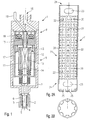
- Fig. 1 shows for better understanding of the invention in a highly schematic representation of a for fitting with a pipe spring designed according to the invention suitable fuel injection valve.
- the fuel injection valve 1 shown in Fig. 1 is in particular as a fuel injection valve 1 for direct Injecting fuel into one not closer illustrated combustion chamber of an internal combustion engine suitable.
- the fuel injection valve 1 comprises a nozzle body 2, in which a valve needle 3 is guided. This points to a downstream end of a valve closing body 4, which forms a sealing seat with a valve seat surface 5.
- the fuel injection valve 1 is open to the outside Fuel injection valve 1 is formed.
- One in the nozzle body 2 arranged return spring 6 acts on the valve needle 3 so that the fuel injection valve 1 in the rest phase held closed or the valve needle 3 after the Opening phase is returned to its rest position.
- the actuator module 9 comprises a preferably piezoelectric Stapelaktor 10, which by an inventively configured bourdon tube 11 for protection against shear forces is biased.
- the actuator 10 is in the present Embodiment additionally by an encapsulation 12th protected.
- the actuator 10 has an actuator base 13 and a Actuator head 14, which with the tube spring 11, for example are welded.
- the tube spring 11 and the invention Measures will be described below with reference to FIGS. 2A, 2B, 3A and 3B described in more detail.
- the coupler 8 and the actuator module 9 are in one Actuator housing 17 encapsulated. This is the central over a supply port 18 flows around supplied fuel, which through the housing 7 and through the nozzle body. 2 flows to the sealing seat.
- the fuel injection valve 1 is via an electrical plug contact 19 actuated.
- the tube spring 11 is hollow cylindrical and For example, punched out of a sheet, then bent and welded at the butt edge.
- the tube spring 11 on one of End portions 24 projections 25, which integral with the Bourdon tube 11 formed and inflected radially inward are.
- the projections 25 are for positive connection the tube spring 11 with the actuator head 14 or the actuator 13th designed to at least a welding process during assembly to save the actuator 10 in the tube spring 11.
- the projections 25 are, as shown in Fig. 2B, preferably rectangular and about 3 mm wide, so that the flexural rigidity in the manufacturing process not too is high. You can also use rounded edges for one have easier mountability.
- the number of Projections 25 is in principle arbitrary, but should be for uniform force introduction into the actuator 10 at least four. In that shown in Fig. 2B Embodiment, the number of projections is eight. However, more or fewer projections 25 may be used according to the shape of the inserted into the tube spring 11 Actuator 14 or actuator base 13 may be provided.
- the preparation of the projections 25 is preferably carried out by Punching in the same work step as the production the Bourdon tube 11.
- the bending of the projections 25 radially inside can be done in two ways: either become the projections 25 bent immediately after punching before the bourdon tube 11 in its final, tubular shape is brought or the bending takes place after the Bending the punched tube spring 11 and the axial Welding.
- the axial spring action of the tube spring 11 is determined by the Projections 25 in no way negatively affected.
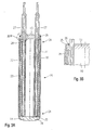
- the actuator module 9 further comprises two contact lugs 27, which serve the electrical contact of the actuator 10 and by means of a plastic extrusion coating 28, which simultaneously surrounds the actuator 10, are fixed to this.
- Fig. 3B is a schematic fragmentary Representation of the designated in Fig. 3A with IIIB section reproduced, which is a further advantageous Embodiment of the inventively designed Bourdon tube 11 represents.
- the projections 25 on the one Side of the actuator 10 is arranged, at which also the Contact lugs 27 are located.
- the positive connection between the Bourdon tube 11 and the actuator 10 thus does not take place over the Actuator head 14, but via the actuator foot 13.
- the two Variants are equivalent to each other.
Landscapes
- Engineering & Computer Science (AREA)
- General Engineering & Computer Science (AREA)
- Mechanical Engineering (AREA)
- Chemical & Material Sciences (AREA)
- Combustion & Propulsion (AREA)
- Fuel-Injection Apparatus (AREA)
Abstract
Description
- Fig. 1
- eine schematisierte Darstellung eines für die Bestückung mit einer erfindungsgemäßen Rohrfeder geeigneten Brennstoffeinspritzventils;
- Fig. 2A
- eine Schnittdarstellung eines Ausführungsbeispiels einer erfindungsgemäß ausgestalteten Rohrfeder;
- Fig. 2B
- eine schematische Aufsicht auf das abströmseitige Ende der erfindungsgemäß ausgestalteten Rohrfeder gemäß Fig. 2A;
- Fig. 3A
- eine schematische Darstellung eines mit einer erfindungsgemäß ausgestalteten Rohrfeder versehenen Aktors; und
- Fig. 3B
- eine schematische ausschnittsweise Darstellung einer weiteren Ausgestaltungsvariante eines mit einer erfindungsgemäß ausgestalteten Rohrfeder versehenen Aktors im Bereich IIIB in Fig. 3A.
Claims (10)
- Rohrfeder (1) für einen piezoelektrischen oder magnetostriktiven Aktor (5), welcher insbesondere zur Betätigung eines Brennstoffeinspritzventils (1) für Brennstoffeinspritzanlagen von Brennkraftmaschinen dient,
dadurch gekennzeichnet, daß die Rohrfeder (11) an einem Endbereich (24) Vorsprünge (25) aufweist. - Rohrfeder nach Anspruch 1,
dadurch gekennzeichnet, daß die Vorsprünge (25) nach radial innen eingebogen sind. - Rohrfeder nach Anspruch 1 oder 2,
dadurch gekennzeichnet, daß die Vorsprünge (25) eine Breite von 1 mm bis 5 mm, vorzugsweise ca. 3 mm, aufweisen. - Rohrfeder nach einem der Ansprüche 1 bis 3,
dadurch gekennzeichnet, daß die Anzahl der Vorsprünge (25) zumindest vier beträgt. - Rohrfeder nach einem der Ansprüche 1 bis 4,
dadurch gekennzeichnet, daß die Vorsprünge (25) rechteckig ausgebildet sind. - Rohrfeder nach einem der Ansprüche 1 bis 5,
dadurch gekennzeichnet, daß die Rohrfeder (11) in einem mittleren Bereich (21) Ausnehmungen (20) und dazwischenliegende Stege (22) aufweist. - Rohrfeder nach einem der Ansprüche 1 bis 6,
dadurch gekennzeichnet, daß an beiden Endbereichen (24) der Rohrfeder (11) Montageeingriffe (23) ausgebildet sind. - Rohrfeder nach einem der Ansprüche 1 bis 7,
dadurch gekennzeichnet, daß zwischen einem Aktorkopf (13) oder einem Aktorfuß (14) des Aktors (10) und den Vorsprüngen (25) der Rohrfeder (11) ein Formschluß besteht. - Rohrfeder nach Anspruch 8,
dadurch gekennzeichnet, daß der Aktorkopf (13) oder der Aktorfuß (14) mit einer umlaufenden Schulter (26) an den Vorsprüngen (25) anliegt. - Rohrfeder nach Anspruch 8 oder 9,
dadurch gekennzeichnet, daß der jeweils nicht in Formschluß mit den Vorsprüngen (25) der Rohrfeder (11) stehende Aktorfuß (14) oder Aktorkopf (13) mit der Rohrfeder über eine Schweißnaht (29) verbunden ist.
Applications Claiming Priority (2)
| Application Number | Priority Date | Filing Date | Title |
|---|---|---|---|
| DE10338080 | 2003-08-19 | ||
| DE10338080A DE10338080A1 (de) | 2003-08-19 | 2003-08-19 | Rohrfeder für Aktor |
Publications (2)
| Publication Number | Publication Date |
|---|---|
| EP1508720A1 true EP1508720A1 (de) | 2005-02-23 |
| EP1508720B1 EP1508720B1 (de) | 2008-10-01 |
Family
ID=34042200
Family Applications (1)
| Application Number | Title | Priority Date | Filing Date |
|---|---|---|---|
| EP04018547A Expired - Lifetime EP1508720B1 (de) | 2003-08-19 | 2004-08-05 | Rohrfeder für Aktor |
Country Status (2)
| Country | Link |
|---|---|
| EP (1) | EP1508720B1 (de) |
| DE (2) | DE10338080A1 (de) |
Families Citing this family (1)
| Publication number | Priority date | Publication date | Assignee | Title |
|---|---|---|---|---|
| DE102024200109A1 (de) * | 2024-01-05 | 2025-07-10 | Robert Bosch Gesellschaft mit beschränkter Haftung | Kraftstoffinjektor für gasförmige oder flüssige Kraftstoffe |
Citations (4)
| Publication number | Priority date | Publication date | Assignee | Title |
|---|---|---|---|---|
| DE19653555A1 (de) * | 1996-12-20 | 1998-06-25 | Siemens Ag | Piezoelektrischer Aktor |
| DE19951012A1 (de) | 1999-10-22 | 2001-04-26 | Bosch Gmbh Robert | Aktor |
| US20030034594A1 (en) * | 2001-08-16 | 2003-02-20 | Robert Bosch Gmbh | Spring bushing and method for producing a spring bushing |
| WO2003033933A1 (de) * | 2001-10-09 | 2003-04-24 | Siemens Aktiengesellschaft | Verfahren zur herstellung einer rohrfeder sowie aktoreinheit mit einer solchen rohrfeder |
Family Cites Families (4)
| Publication number | Priority date | Publication date | Assignee | Title |
|---|---|---|---|---|
| US3042391A (en) * | 1959-09-25 | 1962-07-03 | Garrett Corp | Compression spring |
| US3712604A (en) * | 1971-04-26 | 1973-01-23 | Motorola Inc | Mechanical spring constant load device |
| EP1021662B1 (de) * | 1998-08-06 | 2005-10-26 | Siemens Aktiengesellschaft | Piezoelektrische aktoreinheit |
| DE10055639A1 (de) * | 2000-11-10 | 2002-05-23 | Siemens Ag | Injektor zum Einspritzen von Kraftstoff in einen Brennraum |
-
2003
- 2003-08-19 DE DE10338080A patent/DE10338080A1/de not_active Withdrawn
-
2004
- 2004-08-05 DE DE502004008142T patent/DE502004008142D1/de not_active Expired - Lifetime
- 2004-08-05 EP EP04018547A patent/EP1508720B1/de not_active Expired - Lifetime
Patent Citations (4)
| Publication number | Priority date | Publication date | Assignee | Title |
|---|---|---|---|---|
| DE19653555A1 (de) * | 1996-12-20 | 1998-06-25 | Siemens Ag | Piezoelektrischer Aktor |
| DE19951012A1 (de) | 1999-10-22 | 2001-04-26 | Bosch Gmbh Robert | Aktor |
| US20030034594A1 (en) * | 2001-08-16 | 2003-02-20 | Robert Bosch Gmbh | Spring bushing and method for producing a spring bushing |
| WO2003033933A1 (de) * | 2001-10-09 | 2003-04-24 | Siemens Aktiengesellschaft | Verfahren zur herstellung einer rohrfeder sowie aktoreinheit mit einer solchen rohrfeder |
Also Published As
| Publication number | Publication date |
|---|---|
| EP1508720B1 (de) | 2008-10-01 |
| DE10338080A1 (de) | 2005-03-10 |
| DE502004008142D1 (de) | 2008-11-13 |
Similar Documents
| Publication | Publication Date | Title |
|---|---|---|
| EP1634340B1 (de) | Rohrfeder für aktor und verfahren zur montage der rohrfeder | |
| EP0877860B1 (de) | Brennstoffeinspritzventil | |
| DE69922087T2 (de) | Brennstoffeinspritzdüse | |
| EP1115970B1 (de) | Brennstoffeinspritzventil | |
| EP1490594B1 (de) | Kraftstoffeinspritzventil | |
| EP1756415A1 (de) | Kraftstoffinjektor mit variabler aktorübersetzung | |
| EP2137403B1 (de) | Federhülse für kraftstoffinjektor | |
| EP1519072A1 (de) | Rohrfeder für Aktor | |
| EP1531258A2 (de) | Kraftstoffeinspritzventil | |
| EP1252433A2 (de) | Kraftstoffeinspritzventil für brennkraftmaschinen | |
| DE10310787A1 (de) | Rohrfeder für Aktor und Verfahren zur Montage der Rohrfeder | |
| EP1432908B1 (de) | Brennstoffeinspritzventil | |
| DE10361761A1 (de) | Brennstoffeinspritzventil | |
| EP1508720A1 (de) | Rohrfeder für Aktor | |
| DE102006017034B4 (de) | Piezo-Aktor, Verfahren zum Herstellen eines Piezo-Aktors und Einspritzsystem mit einem solchen | |
| DE19952057A1 (de) | Brennstoffeinspritzventil | |
| WO2006128773A1 (de) | Kraftstoffeinspritzdüse | |
| EP1664524B1 (de) | Ventileinrichtung, insbesondere ein kraftstoffeinspritzventil für eine brennkraftmaschine | |
| EP3036431B1 (de) | Piezoaktor für einen kraftstoffinjektor und kraftstoffinjektor | |
| DE60304442T2 (de) | Messvorrichtung mit Durchfluss-Kalibriereinrichtung sowie Verfahren zur Einstellung der Durchflussmenge der Messvorrichtung | |
| EP1121526A1 (de) | Brennstoffeinspritzventil | |
| DE102006036782B4 (de) | Injektor | |
| DE10305508A1 (de) | Kraftstoffeinspritzventil für eine Brennkraftmaschine sowie Verfahren zum Betreiben einer Brennkraftmaschine | |
| DE10326343A1 (de) | Brennstoffeinspritzventil | |
| EP2085606A1 (de) | Zwischenplatte für einen Kraftstoffinjektor sowie Kraftstoffinjektor |
Legal Events
| Date | Code | Title | Description |
|---|---|---|---|
| PUAI | Public reference made under article 153(3) epc to a published international application that has entered the european phase |
Free format text: ORIGINAL CODE: 0009012 |
|
| AK | Designated contracting states |
Kind code of ref document: A1 Designated state(s): AT BE BG CH CY CZ DE DK EE ES FI FR GB GR HU IE IT LI LU MC NL PL PT RO SE SI SK TR |
|
| AX | Request for extension of the european patent |
Extension state: AL HR LT LV MK |
|
| 17P | Request for examination filed |
Effective date: 20050823 |
|
| AKX | Designation fees paid |
Designated state(s): DE FR GB IT |
|
| 17Q | First examination report despatched |
Effective date: 20060306 |
|
| GRAP | Despatch of communication of intention to grant a patent |
Free format text: ORIGINAL CODE: EPIDOSNIGR1 |
|
| GRAS | Grant fee paid |
Free format text: ORIGINAL CODE: EPIDOSNIGR3 |
|
| GRAA | (expected) grant |
Free format text: ORIGINAL CODE: 0009210 |
|
| AK | Designated contracting states |
Kind code of ref document: B1 Designated state(s): DE FR GB IT |
|
| REG | Reference to a national code |
Ref country code: GB Ref legal event code: FG4D Free format text: NOT ENGLISH |
|
| REF | Corresponds to: |
Ref document number: 502004008142 Country of ref document: DE Date of ref document: 20081113 Kind code of ref document: P |
|
| PLBE | No opposition filed within time limit |
Free format text: ORIGINAL CODE: 0009261 |
|
| STAA | Information on the status of an ep patent application or granted ep patent |
Free format text: STATUS: NO OPPOSITION FILED WITHIN TIME LIMIT |
|
| 26N | No opposition filed |
Effective date: 20090702 |
|
| PGFP | Annual fee paid to national office [announced via postgrant information from national office to epo] |
Ref country code: GB Payment date: 20140821 Year of fee payment: 11 Ref country code: FR Payment date: 20140819 Year of fee payment: 11 |
|
| PGFP | Annual fee paid to national office [announced via postgrant information from national office to epo] |
Ref country code: IT Payment date: 20140825 Year of fee payment: 11 |
|
| GBPC | Gb: european patent ceased through non-payment of renewal fee |
Effective date: 20150805 |
|
| PG25 | Lapsed in a contracting state [announced via postgrant information from national office to epo] |
Ref country code: IT Free format text: LAPSE BECAUSE OF NON-PAYMENT OF DUE FEES Effective date: 20150805 |
|
| REG | Reference to a national code |
Ref country code: FR Ref legal event code: ST Effective date: 20160429 |
|
| PG25 | Lapsed in a contracting state [announced via postgrant information from national office to epo] |
Ref country code: GB Free format text: LAPSE BECAUSE OF NON-PAYMENT OF DUE FEES Effective date: 20150805 |
|
| PG25 | Lapsed in a contracting state [announced via postgrant information from national office to epo] |
Ref country code: FR Free format text: LAPSE BECAUSE OF NON-PAYMENT OF DUE FEES Effective date: 20150831 |
|
| PGFP | Annual fee paid to national office [announced via postgrant information from national office to epo] |
Ref country code: DE Payment date: 20171026 Year of fee payment: 14 |
|
| REG | Reference to a national code |
Ref country code: DE Ref legal event code: R119 Ref document number: 502004008142 Country of ref document: DE |
|
| PG25 | Lapsed in a contracting state [announced via postgrant information from national office to epo] |
Ref country code: DE Free format text: LAPSE BECAUSE OF NON-PAYMENT OF DUE FEES Effective date: 20190301 |