EP1508673A2 - Procédé de fabrication d'un moteur à turbine à gaz - Google Patents
Procédé de fabrication d'un moteur à turbine à gaz Download PDFInfo
- Publication number
- EP1508673A2 EP1508673A2 EP04254882A EP04254882A EP1508673A2 EP 1508673 A2 EP1508673 A2 EP 1508673A2 EP 04254882 A EP04254882 A EP 04254882A EP 04254882 A EP04254882 A EP 04254882A EP 1508673 A2 EP1508673 A2 EP 1508673A2
- Authority
- EP
- European Patent Office
- Prior art keywords
- rim
- assembly
- ring member
- casing
- accordance
- Prior art date
- Legal status (The legal status is an assumption and is not a legal conclusion. Google has not performed a legal analysis and makes no representation as to the accuracy of the status listed.)
- Withdrawn
Links
- 238000000034 method Methods 0.000 title abstract description 11
- 238000003754 machining Methods 0.000 abstract description 11
- 230000008878 coupling Effects 0.000 abstract description 7
- 238000010168 coupling process Methods 0.000 abstract description 7
- 238000005859 coupling reaction Methods 0.000 abstract description 7
- 230000000712 assembly Effects 0.000 abstract description 3
- 238000000429 assembly Methods 0.000 abstract description 3
- 239000007789 gas Substances 0.000 description 11
- 239000000463 material Substances 0.000 description 6
- 238000001816 cooling Methods 0.000 description 5
- 239000000446 fuel Substances 0.000 description 2
- 230000002411 adverse Effects 0.000 description 1
- 239000000567 combustion gas Substances 0.000 description 1
- 230000002401 inhibitory effect Effects 0.000 description 1
- 238000004519 manufacturing process Methods 0.000 description 1
- 238000011144 upstream manufacturing Methods 0.000 description 1
Images

Classifications
-
- F—MECHANICAL ENGINEERING; LIGHTING; HEATING; WEAPONS; BLASTING
- F01—MACHINES OR ENGINES IN GENERAL; ENGINE PLANTS IN GENERAL; STEAM ENGINES
- F01D—NON-POSITIVE DISPLACEMENT MACHINES OR ENGINES, e.g. STEAM TURBINES
- F01D25/00—Component parts, details, or accessories, not provided for in, or of interest apart from, other groups
- F01D25/24—Casings; Casing parts, e.g. diaphragms, casing fastenings
-
- F—MECHANICAL ENGINEERING; LIGHTING; HEATING; WEAPONS; BLASTING
- F01—MACHINES OR ENGINES IN GENERAL; ENGINE PLANTS IN GENERAL; STEAM ENGINES
- F01D—NON-POSITIVE DISPLACEMENT MACHINES OR ENGINES, e.g. STEAM TURBINES
- F01D11/00—Preventing or minimising internal leakage of working-fluid, e.g. between stages
- F01D11/08—Preventing or minimising internal leakage of working-fluid, e.g. between stages for sealing space between rotor blade tips and stator
- F01D11/14—Adjusting or regulating tip-clearance, i.e. distance between rotor-blade tips and stator casing
- F01D11/16—Adjusting or regulating tip-clearance, i.e. distance between rotor-blade tips and stator casing by self-adjusting means
- F01D11/18—Adjusting or regulating tip-clearance, i.e. distance between rotor-blade tips and stator casing by self-adjusting means using stator or rotor components with predetermined thermal response, e.g. selective insulation, thermal inertia, differential expansion
Definitions
- This invention relates generally to gas turbine engines, and more specifically to turbine casings used with gas turbine engines.
- Gas turbine engines generally include, in serial flow arrangement, a high pressure compressor for compressing air flowing through the engine, a combustor in which fuel is mixed with the compressed air and ignited to form a high energy gas stream, and a high pressure turbine.
- the high pressure compressor, combustor and high pressure turbine are sometimes collectively referred to as the core engine.
- Such gas turbine engines also may include a low pressure compressor, or booster, for supplying compressed air to the high pressure compressor.
- At least some known turbines include a rotor assembly including a plurality of rows of rotor blades. Each rotor blade extends radially outward from a blade platform to a tip. A plurality of shrouds couple together to form a flow path casing that extends substantially circumferentially around the rotor assembly, such that a tip clearance is defined between each respective rotor blade tip and the casing.
- the tip clearance is designed to be a minimum, while still being sized large enough to facilitate rub-free engine operation through a range of available engine operating conditions.
- turbine performance may be influenced by the tip clearance between turbine blade tips and the shroud.
- leakage across the rotor blade tips may adversely limit the performance of the turbine assembly.
- To facilitate maintaining blade tip clearance at least some known shroud designs attempt to match the rate of thermal expansion of the stator case to the rate of thermal expansion of the turbine rotor assembly by supplying a variable amount of cooling fan air to the casing flanges. Cooling the flanges facilitates controlling thermal movement to facilitate eliminating rocking of the shrouds. The mass at the flange also pushes the casing downward to facilitate maintaining blade tip clearances.
- casing members include a pseudo flange which adds structural integrity to the shroud casing.
- the pseudo flange is hourglass-shaped with a large mass of material formed at its outer diameter and a thin mid section.
- fabricating such pseudo flanges may be both expensive and time consuming.
- a method according to the invention for fabricating a turbine casing including a plurality of turbine shroud assemblies includes providing a base casing having a forward mounting flange and an aft mounting flange and at least one channel defined therebetween, machining a rim on the base casing proximate the at least one channel, and coupling a ring member to the base casing with an interference fit, such that the rim is at least partially received within a groove formed within the ring member.
- an engine casing assembly for a gas turbine engine.
- the assembly includes a base casing that includes a forward flange, an aft flange, and a body extending therebetween.
- the body includes at least one channel defined therein.
- An annular ring member is coupled to the base casing. The ring member is configured to thermally expand at a rate that is substantially identical to a rate of thermal expansion of the forward and aft flanges.
- a gas turbine engine in another aspect, includes a turbine section including a turbine, and an outer casing assembly circumscribing the turbine.
- the casing assembly includes a base casing including a forward flange, an aft flange, and a body extending therebetween.
- the body includes at least one channel defined therein.
- the casing assembly further includes an annular ring member coupled to the base casing. The ring member is configured to thermally expand at a rate that is substantially identical to a rate of thermal expansion of the forward and aft flanges.
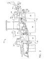
- Figure 1 is a schematic illustration of a gas turbine engine 10 including a low pressure compressor 12, a high pressure compressor 14, and a combustor assembly 16.
- Engine 10 also includes a high pressure turbine 18, and a low pressure turbine 20 arranged in a serial, axial flow relationship. Compressor 12 and turbine 20 are coupled by a first shaft 24, and compressor 14 and turbine 18 are coupled by a second shaft 26.
- engine 10 is an GE90 engine commercially available from General Electric Company, Cincinnati, Ohio.
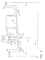
- FIG. 2 is a schematic illustration of a portion of high-pressure turbine 18.
- Figure 3 is an enlarged cross sectional view of a portion of high pressure turbine 18.
- Turbine 18 includes a plurality of stages 30, each of which includes a row of turbine blades 32 and a row of stator vanes 34.
- Turbine blades 32 are supported by rotor disks (not shown), that are coupled to rotor shaft 26.
- Stator casing 36 extends circumferentially around turbine blades 32 and stator vanes 34, such that vanes 34 are supported by casing 36.
- Casing 36 includes a base case segment 38.
- Case segment 38 includes a forward mounting hook 40 and an intermediate mounting hook 41.
- Mounting hooks 40 and 41 define a shroud channel 52 in case segment 38.
- a forward shroud assembly 42 in shroud channel 52 is coupled to mounting hooks 40 and 41.
- Case segment 38 also includes an aft mounting hook 50 that is coupled to an adjacent downstream shroud assembly 43.
- Each shroud assembly 42 and 43 includes a shroud 44 and 45 that are each radially outward of turbine blade tips 46 such that a tip clearance 48 is defined between shrouds 44 and 45 and turbine blade tips 46.
- Case segment 38 also includes a forward mounting flange 54 and an aft mounting flange 56 for coupling case segment 38 substantially axially within engine 10.
- Forward mounting hook 40 extends radially inward from forward mounting flange 54
- aft mounting hook 50 extends radially inward of aft mounting flange 56.
- a mounting hook 51 is coupled between mounting flange 56 of case segment 38 and a mounting flange 58 extending from an adjacent case segment 59.
- shroud assembly mounting hooks 50 and 51 are both positioned at case segment mounting flanges, specifically, mounting flange 56 and mounting flange 58.
- a pseudo flange assembly 60 extends from case segment 38 radially opposite intermediate mounting hook 41.
- Pseudo flange 60 includes a rim 62 and a ring 64 that is coupled to an outer diameter of rim 62. More specifically, rim 62 has a radius R 1 measured with respect to an engine center line 66 that is slightly larger than one of a radius R 2 of forward case segment mounting flange 54 and a radius R 3 of aft mounting flange 56.
- Rim 62 is defined within base casing 38 radially opposite intermediate mounting hook 41 of shroud assembly 42.
- rim 62 is formed via a machining process.
- rim 62 has straight parallel sides 68, 70 to facilitate the machining.
- rim sides 68, 70 are non-parallel.
- Ring 64 has a width W 1 that is greater than a width W 2 of rim 62 and includes a groove 72 defined therein. Grove 72 is sized to receive at least a portion of an outer periphery of rim 62. Ring 64 also includes a lip 74 that circumscribes each side 76, 78 of groove 72 to facilitate inhibiting axial movement between ring 64 and rim 62. In one embodiment, ring 64 is coupled to rim 62 with a shrink fit engagement. Ring 64 is separately machined and can be fabricated in any geometric shape. Ring 64 can also be fabricated from a material different from the case material as long as ring 64 is sized such that the thermal characteristics of ring 64 and rim 62 in combination can be matched to the thermal characteristics of the case segment mounting flanges 54 and 56.
- Pseudo flange 60 is formed by machining ring 62 into base case segment 38 at the location of intermediate mounting hook 41 of shroud assembly 42.
- rim 62 is machined with generally straight parallel sides.
- Rim 62 is machined with a radius R 1 slightly larger than one of radius R 2 of forward mounting flange 54 and radius R 3 of aft mounting flange 56 such that rim 62 will have a diameter (not shown) that is also slightly larger than one of a diameter (not shown) of forward mounting flange 54 and a diameter (not shown) of aft mounting flange 56.
- Ring 64 is machined with a groove 72 sized to receive the outer periphery of rim 62.
- Ring 64 includes a lip 74 on each side of groove 72 to inhibit any axial movement of ring 64 with respect to rim 62. After fabrication, ring 64 is heated so that it expands sufficiently to pass over one of forward mounting flange 54 and aft mounting flange 56 so that it can be fitted on rim 62. A shrink fit is created as ring 64 cools.
- turbine performance is influenced by tip clearance 48, and as such, it is desired to maintain tip clearance 48 to a designed minimum distance while preventing blade tips 46 from contacting shrouds 44 and 45.
- tip clearance 48 it is desired to substantially match the thermal growth of the turbine casing 36, including case segment 38, to that of the rotor disks (not shown) and turbine blades 32.
- Pseudo flange assembly 60 is provided on base case segment 38 so that thermal growth characteristics of case segment 38 at mounting hooks 40 and 41 for shroud assembly 42 can be matched with the thermal characteristics of forward and rearward case mounting flanges 54 and 56, respectively, so that turbine blade tip to shroud clearance 48 is facilitated to be maintained.
- the thermal expansion matching is facilitated by cooling the casing flanges, including flanges 54 and 56, and pseudo flange assembly 60 with a variable amount of cooling air.
- the cooling air is compressor discharge air.
- the above-described pseudo flange provides a cost-effective flange that can be used for matching thermal growth characteristics in a case segment so that turbine blade tip to shroud clearances may be maintained.
- the pseudo flange is of a simplified design that also allows for simplifying the design of bleed ports in the area of the pseudo flange.
- the pseudo flange also provides for the use of a ring of a different material than that of the casing which may provide a better thermal match due to differing coefficients of thermal expansion between the ring material and the case material.
Landscapes
- Engineering & Computer Science (AREA)
- Mechanical Engineering (AREA)
- General Engineering & Computer Science (AREA)
- Turbine Rotor Nozzle Sealing (AREA)
Applications Claiming Priority (2)
| Application Number | Priority Date | Filing Date | Title |
|---|---|---|---|
| US642719 | 2003-08-18 | ||
| US10/642,719 US6848885B1 (en) | 2003-08-18 | 2003-08-18 | Methods and apparatus for fabricating gas turbine engines |
Publications (2)
| Publication Number | Publication Date |
|---|---|
| EP1508673A2 true EP1508673A2 (fr) | 2005-02-23 |
| EP1508673A3 EP1508673A3 (fr) | 2007-06-13 |
Family
ID=34063447
Family Applications (1)
| Application Number | Title | Priority Date | Filing Date |
|---|---|---|---|
| EP04254882A Withdrawn EP1508673A3 (fr) | 2003-08-18 | 2004-08-13 | Procédé de fabrication d'un moteur à turbine à gaz |
Country Status (3)
| Country | Link |
|---|---|
| US (1) | US6848885B1 (fr) |
| EP (1) | EP1508673A3 (fr) |
| JP (1) | JP2005061418A (fr) |
Cited By (6)
| Publication number | Priority date | Publication date | Assignee | Title |
|---|---|---|---|---|
| WO2006046969A2 (fr) * | 2004-05-17 | 2006-05-04 | Cardarella L James Jr | Renforcement de carter de turbine dans un moteur propulseur a turbine a gaz |
| EP2267279A1 (fr) * | 2009-06-03 | 2010-12-29 | Rolls-Royce plc | Ensemble d'aube de guidage |
| US8191254B2 (en) | 2004-09-23 | 2012-06-05 | Carlton Forge Works | Method and apparatus for improving fan case containment and heat resistance in a gas turbine jet engine |
| WO2014051686A1 (fr) * | 2012-09-26 | 2014-04-03 | United Technologies Corporation | Carter de turbine haute pression et carter intermédiaire de turbine combinés |
| WO2015021222A1 (fr) | 2013-08-07 | 2015-02-12 | United Technologies Corporation | Ensemble régulateur de jeu |
| EP3153671A1 (fr) * | 2015-10-08 | 2017-04-12 | MTU Aero Engines GmbH | Dispositif de protection pour turbomachine |
Families Citing this family (6)
| Publication number | Priority date | Publication date | Assignee | Title |
|---|---|---|---|---|
| US7377742B2 (en) * | 2005-10-14 | 2008-05-27 | General Electric Company | Turbine shroud assembly and method for assembling a gas turbine engine |
| US8079773B2 (en) * | 2005-10-18 | 2011-12-20 | General Electric Company | Methods and apparatus for assembling composite structures |
| US8197186B2 (en) * | 2007-06-29 | 2012-06-12 | General Electric Company | Flange with axially extending holes for gas turbine engine clearance control |
| US8393855B2 (en) * | 2007-06-29 | 2013-03-12 | General Electric Company | Flange with axially curved impingement surface for gas turbine engine clearance control |
| US9598981B2 (en) * | 2013-11-22 | 2017-03-21 | Siemens Energy, Inc. | Industrial gas turbine exhaust system diffuser inlet lip |
| US9784132B2 (en) * | 2015-04-20 | 2017-10-10 | Pratt & Whitney Canada Corp. | Voltage discharge channelling assembly for a gas turbine engine |
Citations (6)
| Publication number | Priority date | Publication date | Assignee | Title |
|---|---|---|---|---|
| FR996476A (fr) * | 1949-10-01 | 1951-12-19 | Cem Comp Electro Mec | Cylindre pour turbines à gaz |
| US2749026A (en) * | 1951-02-27 | 1956-06-05 | United Aircraft Corp | Stator construction for compressors |
| GB2019954A (en) * | 1978-04-04 | 1979-11-07 | Rolls Royce | Turbomachine housing |
| US5154575A (en) * | 1991-07-01 | 1992-10-13 | United Technologies Corporation | Thermal blade tip clearance control for gas turbine engines |
| EP1104837A2 (fr) * | 1999-12-03 | 2001-06-06 | General Electric Company | Structure de confinement |
| US6514041B1 (en) * | 2001-09-12 | 2003-02-04 | Alstom (Switzerland) Ltd | Carrier for guide vane and heat shield segment |
Family Cites Families (2)
| Publication number | Priority date | Publication date | Assignee | Title |
|---|---|---|---|---|
| US4840026A (en) * | 1988-02-24 | 1989-06-20 | The United States Of America As Represented By The Secretary Of The Air Force | Band clamp apparatus |
| GB9709086D0 (en) * | 1997-05-07 | 1997-06-25 | Rolls Royce Plc | Gas turbine engine cooling apparatus |
-
2003
- 2003-08-18 US US10/642,719 patent/US6848885B1/en not_active Expired - Fee Related
-
2004
- 2004-08-13 EP EP04254882A patent/EP1508673A3/fr not_active Withdrawn
- 2004-08-17 JP JP2004236971A patent/JP2005061418A/ja not_active Withdrawn
Patent Citations (6)
| Publication number | Priority date | Publication date | Assignee | Title |
|---|---|---|---|---|
| FR996476A (fr) * | 1949-10-01 | 1951-12-19 | Cem Comp Electro Mec | Cylindre pour turbines à gaz |
| US2749026A (en) * | 1951-02-27 | 1956-06-05 | United Aircraft Corp | Stator construction for compressors |
| GB2019954A (en) * | 1978-04-04 | 1979-11-07 | Rolls Royce | Turbomachine housing |
| US5154575A (en) * | 1991-07-01 | 1992-10-13 | United Technologies Corporation | Thermal blade tip clearance control for gas turbine engines |
| EP1104837A2 (fr) * | 1999-12-03 | 2001-06-06 | General Electric Company | Structure de confinement |
| US6514041B1 (en) * | 2001-09-12 | 2003-02-04 | Alstom (Switzerland) Ltd | Carrier for guide vane and heat shield segment |
Cited By (13)
| Publication number | Priority date | Publication date | Assignee | Title |
|---|---|---|---|---|
| EP2314831A1 (fr) * | 2004-05-17 | 2011-04-27 | Carlton Forge Works | Renforcement de carter de turbine dans un moteur propulseur à turbine |
| WO2006046969A3 (fr) * | 2004-05-17 | 2006-06-22 | Cardarella L James Jr | Renforcement de carter de turbine dans un moteur propulseur a turbine a gaz |
| WO2006046969A2 (fr) * | 2004-05-17 | 2006-05-04 | Cardarella L James Jr | Renforcement de carter de turbine dans un moteur propulseur a turbine a gaz |
| US8454298B2 (en) | 2004-09-23 | 2013-06-04 | Carlton Forge Works | Fan case reinforcement in a gas turbine jet engine |
| US8191254B2 (en) | 2004-09-23 | 2012-06-05 | Carlton Forge Works | Method and apparatus for improving fan case containment and heat resistance in a gas turbine jet engine |
| US8317456B2 (en) | 2004-09-23 | 2012-11-27 | Carlton Forge Works | Fan case reinforcement in a gas turbine jet engine |
| EP2267279A1 (fr) * | 2009-06-03 | 2010-12-29 | Rolls-Royce plc | Ensemble d'aube de guidage |
| WO2014051686A1 (fr) * | 2012-09-26 | 2014-04-03 | United Technologies Corporation | Carter de turbine haute pression et carter intermédiaire de turbine combinés |
| WO2015021222A1 (fr) | 2013-08-07 | 2015-02-12 | United Technologies Corporation | Ensemble régulateur de jeu |
| EP3030755A4 (fr) * | 2013-08-07 | 2017-03-08 | United Technologies Corporation | Ensemble régulateur de jeu |
| US10132187B2 (en) | 2013-08-07 | 2018-11-20 | United Technologies Corporation | Clearance control assembly |
| EP3153671A1 (fr) * | 2015-10-08 | 2017-04-12 | MTU Aero Engines GmbH | Dispositif de protection pour turbomachine |
| US10533449B2 (en) | 2015-10-08 | 2020-01-14 | MTU Aero Engines AG | Containment for a continuous flow machine |
Also Published As
| Publication number | Publication date |
|---|---|
| US20050042090A1 (en) | 2005-02-24 |
| US6848885B1 (en) | 2005-02-01 |
| JP2005061418A (ja) | 2005-03-10 |
| EP1508673A3 (fr) | 2007-06-13 |
Similar Documents
| Publication | Publication Date | Title |
|---|---|---|
| CA2532704C (fr) | Installation d'etancheification de carenage de turbine a gaz | |
| US7094029B2 (en) | Methods and apparatus for controlling gas turbine engine rotor tip clearances | |
| CA2870740C (fr) | Profil aerodynamique de turbine a commande d'epaisseur de paroi locale | |
| EP1630385B1 (fr) | Procédé et appareil pour maintenir le jeu des extrémités des aubes d'un rotor de turbine | |
| US9500095B2 (en) | Turbine shroud segment sealing | |
| US7165937B2 (en) | Methods and apparatus for maintaining rotor assembly tip clearances | |
| EP1384858A2 (fr) | Refroidissement de la surface intérieure de l'enveloppe de stateur dans la section basse pression d'une turbine à gaz | |
| EP2586992B1 (fr) | Étanchéité d'une aube tournante comportant des passages d'air de refroidissement | |
| EP2365235A1 (fr) | Joint de bordure de turbine refroidie | |
| EP1686242A2 (fr) | Méthode et appareil pour maintenir le jeu des extrémités des aubes d'un rotor de turbine | |
| JP6329657B2 (ja) | タービンシュラウドの密封冷却 | |
| US6848885B1 (en) | Methods and apparatus for fabricating gas turbine engines | |
| EP1609950B1 (fr) | Manchon crénelé pour aube de turbomachine | |
| US20190218925A1 (en) | Turbine engine shroud | |
| JP2008133829A (ja) | タービンエンジンにおける損失の削減を容易にする装置 | |
| CA2951112A1 (fr) | Collecteur destine a un systeme de controle du degagement et methode de fabrication | |
| CA3010385A1 (fr) | Protecteur de profil dynamique de moteur de turbine | |
| JP2017141823A (ja) | 構成要素の熱応力緩和 | |
| US20210180459A1 (en) | Component for a turbine engine with a conduit | |
| EP3543468B1 (fr) | Ensemble de carénage d'extrémité de turbine avec plusieurs segments de carénage dotés d'un agencement d'étanchéité inter-segments |
Legal Events
| Date | Code | Title | Description |
|---|---|---|---|
| PUAI | Public reference made under article 153(3) epc to a published international application that has entered the european phase |
Free format text: ORIGINAL CODE: 0009012 |
|
| AK | Designated contracting states |
Kind code of ref document: A2 Designated state(s): AT BE BG CH CY CZ DE DK EE ES FI FR GB GR HU IE IT LI LU MC NL PL PT RO SE SI SK TR |
|
| AX | Request for extension of the european patent |
Extension state: AL HR LT LV MK |
|
| PUAL | Search report despatched |
Free format text: ORIGINAL CODE: 0009013 |
|
| AK | Designated contracting states |
Kind code of ref document: A3 Designated state(s): AT BE BG CH CY CZ DE DK EE ES FI FR GB GR HU IE IT LI LU MC NL PL PT RO SE SI SK TR |
|
| AX | Request for extension of the european patent |
Extension state: AL HR LT LV MK |
|
| 17P | Request for examination filed |
Effective date: 20071213 |
|
| AKX | Designation fees paid |
Designated state(s): DE GB IT |
|
| 17Q | First examination report despatched |
Effective date: 20080228 |
|
| STAA | Information on the status of an ep patent application or granted ep patent |
Free format text: STATUS: THE APPLICATION IS DEEMED TO BE WITHDRAWN |
|
| 18D | Application deemed to be withdrawn |
Effective date: 20080710 |