EP1508456A2 - Tyre for motorcycle - Google Patents
Tyre for motorcycle Download PDFInfo
- Publication number
- EP1508456A2 EP1508456A2 EP04017672A EP04017672A EP1508456A2 EP 1508456 A2 EP1508456 A2 EP 1508456A2 EP 04017672 A EP04017672 A EP 04017672A EP 04017672 A EP04017672 A EP 04017672A EP 1508456 A2 EP1508456 A2 EP 1508456A2
- Authority
- EP
- European Patent Office
- Prior art keywords
- tyre
- groove
- axial direction
- phantom
- curvature
- Prior art date
- Legal status (The legal status is an assumption and is not a legal conclusion. Google has not performed a legal analysis and makes no representation as to the accuracy of the status listed.)
- Granted
Links
Images

Classifications
-
- B—PERFORMING OPERATIONS; TRANSPORTING
- B60—VEHICLES IN GENERAL
- B60C—VEHICLE TYRES; TYRE INFLATION; TYRE CHANGING; CONNECTING VALVES TO INFLATABLE ELASTIC BODIES IN GENERAL; DEVICES OR ARRANGEMENTS RELATED TO TYRES
- B60C11/00—Tyre tread bands; Tread patterns; Anti-skid inserts
- B60C11/03—Tread patterns
- B60C11/0306—Patterns comprising block rows or discontinuous ribs
- B60C11/0309—Patterns comprising block rows or discontinuous ribs further characterised by the groove cross-section
-
- B—PERFORMING OPERATIONS; TRANSPORTING
- B60—VEHICLES IN GENERAL
- B60C—VEHICLE TYRES; TYRE INFLATION; TYRE CHANGING; CONNECTING VALVES TO INFLATABLE ELASTIC BODIES IN GENERAL; DEVICES OR ARRANGEMENTS RELATED TO TYRES
- B60C11/00—Tyre tread bands; Tread patterns; Anti-skid inserts
- B60C11/03—Tread patterns
- B60C11/0302—Tread patterns directional pattern, i.e. with main rolling direction
-
- B—PERFORMING OPERATIONS; TRANSPORTING
- B60—VEHICLES IN GENERAL
- B60C—VEHICLE TYRES; TYRE INFLATION; TYRE CHANGING; CONNECTING VALVES TO INFLATABLE ELASTIC BODIES IN GENERAL; DEVICES OR ARRANGEMENTS RELATED TO TYRES
- B60C11/00—Tyre tread bands; Tread patterns; Anti-skid inserts
- B60C11/03—Tread patterns
- B60C11/13—Tread patterns characterised by the groove cross-section, e.g. for buttressing or preventing stone-trapping
-
- B—PERFORMING OPERATIONS; TRANSPORTING
- B60—VEHICLES IN GENERAL
- B60C—VEHICLE TYRES; TYRE INFLATION; TYRE CHANGING; CONNECTING VALVES TO INFLATABLE ELASTIC BODIES IN GENERAL; DEVICES OR ARRANGEMENTS RELATED TO TYRES
- B60C11/00—Tyre tread bands; Tread patterns; Anti-skid inserts
- B60C11/03—Tread patterns
- B60C11/13—Tread patterns characterised by the groove cross-section, e.g. for buttressing or preventing stone-trapping
- B60C11/1307—Tread patterns characterised by the groove cross-section, e.g. for buttressing or preventing stone-trapping with special features of the groove walls
- B60C11/1323—Tread patterns characterised by the groove cross-section, e.g. for buttressing or preventing stone-trapping with special features of the groove walls asymmetric
-
- B—PERFORMING OPERATIONS; TRANSPORTING
- B60—VEHICLES IN GENERAL
- B60C—VEHICLE TYRES; TYRE INFLATION; TYRE CHANGING; CONNECTING VALVES TO INFLATABLE ELASTIC BODIES IN GENERAL; DEVICES OR ARRANGEMENTS RELATED TO TYRES
- B60C11/00—Tyre tread bands; Tread patterns; Anti-skid inserts
- B60C11/03—Tread patterns
- B60C2011/0337—Tread patterns characterised by particular design features of the pattern
- B60C2011/0339—Grooves
- B60C2011/0374—Slant grooves, i.e. having an angle of about 5 to 35 degrees to the equatorial plane
-
- B—PERFORMING OPERATIONS; TRANSPORTING
- B60—VEHICLES IN GENERAL
- B60C—VEHICLE TYRES; TYRE INFLATION; TYRE CHANGING; CONNECTING VALVES TO INFLATABLE ELASTIC BODIES IN GENERAL; DEVICES OR ARRANGEMENTS RELATED TO TYRES
- B60C2200/00—Tyres specially adapted for particular applications
- B60C2200/10—Tyres specially adapted for particular applications for motorcycles, scooters or the like
Definitions
- the present invention relates to a structure of a tyre to be employed for a motorcycle.
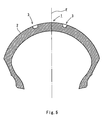
- a tread surface 2 takes such a shape as to be curved outward in a radial direction and a groove 3 is formed on the tread surface 2.
- the tyre 1 is attached to the motorcycle.
- the total weight of a vehicle including the weight of a driver is applied to the tyre 1. Therefore, a portion with which the tyre 1 comes in contact is flattened.
- a contact surface portion 4 is flattened and the groove 3 is also deformed elastically. More specifically, wall surfaces 5 and 6 of the groove 3 are flexed so that both of them approach each other and an opening portion 7 of the groove 3 is reduced. In other words, an opening edge portion 9 of the groove 3 is displaced by S1 outward in an axial direction of the tyre 1 (the direction of an arrow 8) and an opening edge portion 10 of the groove 3 is displaced by S2 inward in the axial direction.
- the tread surface 2 of the tyre 1 is curved as described above. Therefore, the displacement S2 of the opening edge portion 10 is greater than the displacement S1 of the opening edge portion 9.
- the tyre 1 rolls over a road surface. Therefore, the opening edge portions 9 and 10 periodically repeat the elastic deformation. For this reason, the opening edge portion 10 is worn more greatly than the opening edge portion 9 so that the tyre 1 causes a so-called partial wear.
- the tread surface 2 is curved as described above. Therefore, a length in a circumferential direction of the tread surface 2 is gradually shortened outward in the axial direction.
- a slip tends to be generated between the tyre 1 and the ground toward the outer portion in the axial direction over the tread surface 2.
- the opening edge portion 10 tends to be worn still more greatly than the opening edge portion 9.
- the lifetime of the tyre 1 is shortened due to the partial wear.
- the present invention has been made in such a background. It is an object of the present invention to provide a tyre for a motorcycle which can prevent a partial wear and can maintain a performance for a long period of time.
- the present inventor thought that the above-mentioned object could be attained if the opening edge portion of a groove which is formed on a tread surface can be displaced equally because the partial wear is caused by the uneven displacement of the opening edge portion of the groove, that is, the great deformation of the opening edge portion provided on an outside in an axial direction.
- the present invention provides a tyre for a motorcycle comprising a tread portion having a tread surface curved outward in a radial direction, and a groove constituting a tread pattern formed on the tread surface.
- An internal wall surface of the groove takes an almost U shape in which a pair of corner portions is formed to be arcuate surfaces.
- a radius of curvature of the arcuate surface constituting one of the corner portions which is positioned on an inside in an axial direction is set to be smaller than that of the arcuate surface constituting the other corner portion which is positioned on an outside in the axial direction.
- a part of the tread surface is flattened so that a contact surface is formed.
- a load is applied to a portion of the contact surface which is provided with the groove from the opening portion side of the groove inward in the radial direction of the tyre.
- the tread surface is curved. Therefore, the load is applied more acutely in an oblique direction to a portion in the opening edge portion of the groove which is positioned on the outside in the axial direction of the tyre than a portion in the opening edge portion of the groove which is positioned on the inside in the axial direction of the tyre.
- the portion in the opening edge portion of the groove which is positioned on the outside in the axial direction of the tyre tends to be displaced more greatly in the axial direction than the portion in the opening edge portion of the groove which is positioned on the inside in the axial direction of the tyre.
- the groove is formed like an almost U shape and a radius of curvature of the corner portions constituting an internal wall surface which is positioned on the inside in the axial direction is set to be smaller than that of the corner portions which is positioned on the outside in the axial direction.
- a portion of the internal wall surface of the groove which is positioned on the inside in the axial direction is deformed more easily than a portion of the internal wall surface of the groove which is positioned on the outside in the axial direction.
- the arcuate surfaces constituting the corner portions should be set to have radii of curvature of 2 mm or more respectively. Consequently, it is possible to avoid the concentration of a strain caused by the bend of the bottom of the groove. Thus, the bottom of the groove can be prevented from being broken.
- the tyre for a motorcycle may have such a structure that a first phantom circle for defining the arcuate surface constituting the corner portion provided on the inside in the axial direction is inscribed on a second phantom circle for defining the arcuate surface constituting the corner portion provided on the outside in the axial direction.
- the width of the groove can be prevented from being increased unnecessarily, and furthermore, there is increased a difference between the radius of curvature of one of the corner portions constituting the internal wall surface of the groove which is positioned on the inside in the axial direction and the radius of curvature of the other corner portion which is positioned on the outside in the axial direction. More specifically, the radius of curvature of the corner portion positioned on the inside in the axial direction can freely be set within a wide range with respect to the radius of curvature of the corner portion positioned on the outside in the axial direction.
- the amount of the displacement of the opening edge portion positioned on the inside in the axial direction of the groove and that of the opening edge portion positioned on the outside in the axial direction are coincident with each other more accurately.
- each of the corner portions is continuously provided very smoothly. Consequently, it is possible to avoid the generation of a great stress concentration when the opening edge portion of the groove is deformed.
- the phantom points of contact of the first phantom circle and the second phantom circle should be positioned on the outside in the axial direction from a phantom normal which passes through the center of the opening portion of the groove and is orthogonal to a phantom tread line for defining the tread surface and a distance between the phantom normal and the phantom point of contact should be equal to or smaller than one tenth of the width of the groove.
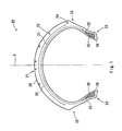
- Fig. 1 shows a section taken along a plane which passes through the center of a tyre 20 for a motorcycle according to an embodiment of the present invention and is orthogonal to an equator plane E of the tyre 20.
- a vertical direction is set to be a radial direction of the tyre 20 and a transverse direction is set to be an axial direction of the tyre 20.
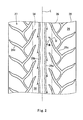
- Fig. 2 shows a tread pattern 27 of the tyre 20.
- the tyre 20 takes an almost symmetrical shape about the equator plane E excluding the tread pattern 27.
- the tyre 20 comprises a tread portion 21, a sidewall portion 22, a bead portion 23, a carcass portion 24 and a band portion 25.
- the tread portion 21 is formed of a crosslinked rubber and a tread surface 26 thereof is formed like an arch to be an outward convex portion in the radial direction.
- the predetermined tread pattern 27 is formed on the tread surface 26.
- the tread pattern 27 is constituted by forming a groove 28 (28a to 28d) on the tread surface 26.
- the groove 28 is formed by a mold in a process of manufacturing the tyre 20.
- the present embodiment features the shape of the internal wall surface of the groove 28.
- the internal wall surface of the groove 28 takes the following shape so that a so-called partial wear of the tyre 20 can be prevented.
- a driver When the motorcycle carries out cornering, generally, a driver inclines the motorcycle inward in a cornering direction. At this time, the tyre comes in contact with the ground at a camber angle with a road surface. A camber thrust is generated on the contact surface of the tyre. The camber thrust is opposed to a centrifugal force generated when the motorcycle carries out the cornering. By the camber thrust, the motorcycle can carry out stable turning. In order to generate a stable camber thrust, the external surface of the tread portion 21, that is, the tread surface 26 is formed to draw a great arch as shown in Fig. 1.
- the schematic structure of the tyre 20 is as follows.
- the sidewall portion 22 is continuously linked to the tread portion 21 and is extended inward in the radial direction from both ends of the tread portion 21.
- the sidewall portion 22 is also formed of a crosslinked rubber.
- the sidewall portion 22 is flexed to absorb a shock from the road surface.
- the sidewall portion 22 prevents the external damage of the carcass portion 24.
- the bead portion 23 is continuously linked to the sidewall portion 22.
- the bead portion 23 includes a bead core 29 and a bead apex 30.
- the bead apex 30 is extended outward in the radial direction from the bead core 29.
- the bead core 29 is formed circularly.
- the bead core 29 is constituted by a plurality of non-extensible wires (typically, wires formed of steel).
- the bead apex 30 is formed of a crosslinked rubber.
- the bead apex 30 is formed to be tapered outward in the radial direction.
- the carcass portion 24 includes a carcass ply 31.
- the carcass ply 31 is provided along the inner peripheral surfaces of the tread portion 21, the sidewall portion 22 and the bead portion 23.
- An end 32 of the carcass ply 31 is laid over the bead core 29 and is extended toward the sidewall portion 22 side.
- the carcass ply 31 has a carcass cord.
- the carcass cord is provided to be extended in a direction of approximately 90 degrees with respect to the equator plane E of the tyre 20. Indeed, it is a matter of course that the direction of the carcass cord is not restricted to this direction.
- the band portion 25 includes a band ply 33.
- the band ply 33 is formed circularly and is provided on an outside in the radial direction of the carcass ply 31. Accordingly, the carcass ply 31 is reinforced by the band ply 33.
- the band ply 31 has a band cord which is covered with a topping rubber.
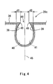
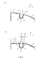
- Fig. 3 shows a phantom section which is orthogonal to the longitudinal direction of a groove 28c formed on the tread surface 26.
- the shape of the internal wall surface of the groove 28c is shown in detail.
- the shape of the internal wall surface of the groove 28c will be described below. The following description is not restricted to the shape of the groove 28c but is applied to the sectional shape of the whole groove 28.
- Each dimension of the tyre 20 is measured in a state in which the tyre 20 is incorporated in a normal rim and the tyre 20 is filled with air to obtain a normal internal pressure, and a camber angle is 0 degree.
- the normal rim implies a rim determined in a standard system including standards on which the tyre 20 depends. "Measuring Rim” in the JATMA standards is the normal rim.
- the normal internal pressure implies an internal pressure determined in a standard system including the standards on which the tyre 20 depends.
- a “maximum air pressure” in the LATMA standards, a “maximum value” described in "TYRE LOAD LIMITS AT VARIOUS PRESSURE” in the TRA standards and "INFLATION PRESSURE in the ETRTO standards are included in the normal internal pressures.
- a region shown in two-dotted chain lines 34 and 35 is a portion to be a contact surface 36 when the tyre 20 is caused to come in contact with the ground.
- the tyre 20 is caused to come in contact with the ground implies a state in which a normal load is applied to the tyre 20.
- the groove 28c is positioned on the end of the contact surface 36.
- the normal load is applied in the radial direction of the tyre 20 in the state in which the tyre 20 is incorporated in the normal rim and the tyre 20 is filled with the air in order to obtain the normal internal pressure, and the camber angle is 0 degree.
- the normal load includes a maximum load capacity defined in the JATMA, a maximum value described in the TRA table "TYRE LOAD LIMITS AT VARIOUS COLD INFLATION PRESSURES" or "LOAD CAPACITY" defined in the ETRTO.
- the normal load is set to be approximately 50 to 60% of the maximum load capacity.
- the normal load usually implies a weight obtained by adding a weight corresponding to one passenger to the weight of a body.
- the groove 28c is formed with the internal wall surface taking an almost U shape. More specifically, the internal wall of the groove 28c includes a bottom face portion 37 and sidewall portions 38 and 39.
- the sidewall portion 38 is positioned on an inside in the axial direction of the tyre 20 and the sidewall portion 39 is positioned on an outside in the axial direction of the tyre 20.
- the sidewall portions 38 and 39 are extended straight in the radial direction of the tyre 20 or a direction crossing the radial direction at a constant angle, respectively.
- the bottom face portion 37 is formed to be linked to the sidewall portions 38 and 39 smoothly and continuously.
- a width B of the groove 28c is set to be 5.0 mm and a depth of the groove 28c is set to be 4.0 mm. Indeed, the width B and the depth of the groove 28c are properly designed and changed corresponding to the specifications of the tyre 20.
- the bottom face portion 37 is formed to be an acruate surface. Both ends of the bottom face portion 37 (that is, portions which are continuously linked to the sidewall portions 38 and 39) constitute corner portions 40 and 41 of the groove 28c.
- the corner portion 40 positioned on the inside in the axial direction is formed to be acruate around a center of curvature P1.
- a radius of curvature R1 of the corner portion 40 is set to be 2.0 mm in the present embodiment.
- the corner portion 41 positioned on the outside in the axial direction is formed to be arcuate around a center of curvature P2.
- a radius of curvature R2 of the corner portion 41 is set to be 4.0 mm in the present embodiment.
- the radii of curvature R1 and R2 are properly designed and changed corresponding to the specifications of the tyre 20. It is preferable that the radii of curvature R1 and R2 should be set to be 2 mm or more. In the present embodiment, a difference between the radius of curvature R1 and the radius of curvature R2 is set to be 2.0 mm. Their difference is properly set.
- the shape of the corner portion 40 (the shape of the arcuate surface) is defined by a first phantom circle 42 having the radius R1 around the center of curvature P1.
- the shape of the corner portion 41 (the shape of the arcuate surface) is defined by a second phantom circle 43 having the radius R2 around the center of curvature P2.
- the first phantom circle 42 and the second phantom circle 43 come in contact with each other at a point of contact 44 (a phantom point of contact).
- the point of contact 44 is shifted by a distance s from the center of the groove 28c outward in the axial direction. In the present embodiment, the distance s is set to be 0.5 mm.
- the distance s is properly designed and changed corresponding to the specifications of the tyre. It is preferable that a ratio of the width B to the distance s should be s/B ⁇ 0.2.
- the center of the groove 28c is defined by a phantom normal 45.
- the phantom normal 45 passes through the center of an opening portion 46 of the groove 28c and is orthogonal to a phantom tread line 47 for defining the tread surface 26.
- the point of contact 44 is placed in a position which is shifted by the distance s from the phantom normal 45 outward in the axial direction of the tyre 20.
- the corner portion 40 is defined by a portion placed inward (leftward in the drawing) in the axial direction from the point of contact 44 and the corner portion 41 is defined by a portion placed outward (rightward in the drawing) in the axial direction from the point of contact 44.
- Fig. 4 shows a state in which the tyre 20 comes in contact with the ground.
- the tyre 20 rolls over the road surface and the specific portion of the groove 28 (for example, the groove 28c) is compressed periodically in the radial direction.
- the tyre 20 When the tyre 20 comes in contact with the ground, the tyre 20 is compressed so that the contact surface 36 is formed.
- the tread portion 21 is constituted by a rubber. Therefore, the sidewall portions 38 and 39 constituting the groove 28c are elastically deformed and opening edge portions 48 and 49 of the groove 28c are displaced. More specifically, the opening edge portion 48 provided on the inside in the axial direction is displaced by a distance d1 outward in the axial direction and the opening edge portion 49 provided on the outside in the axial direction is displaced by a distance d2 inward in the axial direction.
- the radius of curvature R1 of the corner portion 40 of the groove 28c is smaller than the radius of curvature R2 of the corner portion 41.
- the opening edge portion 49 of the groove 28c is positioned on the outside in the axial direction from the opening edge portion 48.
- the opening edge portion 49 usually tends to be displaced more greatly than the opening edge portion 48 (a second effect).
- the radii of curvature R1 and R2 are set to be the dimensions described above. Consequently, the first effect and the second effect interfere with each other. After all, the displacement distance d1 of the opening edge portion 48 is equal to the displacement distance d2 of the opening edge portion 49. For this reason, the partial wear of the tyre 20 can be prevented. As a result, the lifetime of the tyre 20 can be prolonged and a performance can be maintained for a long period of time.
- the radii of curvature R1 and R2 of the corner portions 40 and 41 are set to be 2 mm or more, respectively. Therefore, it is possible to avoid the concentration of a strain caused by the bend of the bottom of the groove. Consequently, the bottom of the groove can be prevented from being broken.
- the corner portions 40 and 41 are defined by the first phantom circle 42 and the second phantom circle 43 respectively in the state in which the first phantom circle 42 is inscribed on the second phantom circle 43. Therefore, the width B of the groove 28c can be prevented from being unnecessarily increased and the difference between the radius of curvature R1 of the corner portion 40 and the radius of curvature R2 of the corner portion 41 is increased. Accordingly, the radius of curvature R1 of the corner portion 40 can be freely set within a wide range with respect to the radius of curvature R2 of the corner portion 41.
- the amounts of displacement of the opening edge portions 48 and 49 in the groove 28c are coincident with each other more accurately so that the partial wear of the tyre 20 can be reduced still more.
- the first phantom circle 42 is inscribed on the second phantom circle 43. Consequently, the corner portion 40 and the corner portion 41 are continuously provided very smoothly. Consequently, a great stress concentration is not caused when the opening edge portions 48 and 49 are deformed.
- the point of contact 44 of the first phantom circle 42 and the second phantom circle 43 is shifted by the distance s from the phantom normal 45.
- the distance s is set to be one tenth or less of the width B of the groove 28c.
- the portion having the radius of curvature R2 occupies 40% of the groove 28c or more. Accordingly, the difference between the portion having the radius of curvature R1 and the portion having the radius of curvature R2 is clear. In other words, a difference between the wear resistance effect of the portion having the radius of curvature R1 and the partial wear resistance effect of the portion having the radius of curvature R2 is clear. As a result, the partial wear of the tyre 20 can be reduced still more.
- the shape of the internal wall surface of the groove 28 does not need to be the same as the shape of the internal wall surface of the groove 28c over the whole periphery of the tyre 20. Indeed, it is ideal that the internal wall surface of the groove 28 takes the same shape as the shape of the internal wall surface of the groove 28c.
- at least 50% of the sum of a length in the longitudinal direction of the groove 28 (the grooves 28a to 28c) included in the contact surface 36 (the region shown in the two-dotted chain lines 34 and 35 in Fig. 2) formed when the normal load is applied should take the same shape as the shape of the internal wall surface of the groove 28c.
- Table 1 shows a result obtained by the execution of a comparison test for a comparative example.
- the size of a tyre according to each of the examples and the comparative example is 120/70ZR18M/C(59W)D220FST T/L.
- a difference in a tyre wearing way depending on a difference in the shape of the groove of the tyre is measured.
- the shape of the groove of the tyre is specified by a radius of curvature R1 of a corner portion provided on an inside in an axial direction, a radius of curvature R2 of a corner portion provided on an outside in the axial direction, and the presence of the point of contact of a phantom circle for defining each of the corner portions and a position thereof.
- the initial depth of the groove of the tyre is 4.0 mm.
- the performance of the tyre is decided depending on the presence of a partial wear.
- the shape of the groove of the tyre according to each of the examples and the comparative example is as follows.
- the tyre according to the comparative example has a radius of curvature R1 of 2.5 mm and a radius of curvature R2 of 2.5 mm, and has no point of contact of a phantom circle.
- the tyre according to an example 1 has a radius of curvature R1 of 2.0 mm and a radius of curvature R2 of 4.0 mm, and the point of contact of a phantom circle is present on an outside in an axial direction from a phantom normal passing through the center of a groove.
- the point of contact is positioned at a distance of 1/10 of a width B of the groove from the phantom normal.
- the tyre according to an example 2 has a radius of curvature R1 of 2.3 mm and a radius of curvature R2 of 3.0 mm, and the point of contact of a phantom circle is present on an outside in an axial direction from a phantom normal passing through the center of a groove.
- the point of contact is positioned at a distance which is greater than 1/10 of the width B of a groove and is smaller than 1/6 thereof from the phantom normal.
- the tyre according to each of the comparative example and the examples is attached to a motorcycle and a driver accelerates the motorcycle to a speed of 120 km/h, and then carries out full braking (ABS operation) to decelerate the motorcycle to 40 km/h.
- ABS operation full braking
- the driver performed and repeated this operation every 500 m until a mileage of 1500 km was obtained.
- Depths on the inside and outside in the axial direction of the groove of the tyre were measured respectively after the running (Table 1).
- the depth of the groove obtained after the running has a great difference between the inside in the axial direction and the outside in the axial direction. This indicates that a partial wear is generated on the tyre.
- the depth of the groove has a difference of 0 . 2 mm between the inside in the axial direction and the outside in the axial direction also at a mileage of 1500 km. In other words, the partial wear of the tyre can be suppressed effectively.
- the partial wear is generated in the same manner as the tyre according to the comparative example. Consequently, the point of contact of the phantom circle for defining each corner portion of the groove of the tyre is to be positioned at a distance of 1/10 or less of the width B of the groove from the phantom normal of the groove.
Landscapes
- Engineering & Computer Science (AREA)
- Mechanical Engineering (AREA)
- Tires In General (AREA)
Abstract
Description

Claims (4)
- A tyre for a motorcycle comprising:wherein an internal wall surface of the groove takes an almost U shape in which a pair of corner portions is formed to be arcuate surfaces, anda tread portion having a tread surface curved outward in a radial direction; anda groove constituting a tread pattern formed on the tread surface,
a radius of curvature of the arcuate surface constituting one of the corner portions which is positioned on an inside in an axial direction is set to be smaller than that of the arcuate surface constituting the other corner portion which is positioned on an outside in the axial direction. - The tyre for a motorcycle according to claim 1, wherein the arcuate surfaces constituting the corner portions have the radii of curvature of 2 mm or more, respectively.
- The tyre for a motorcycle according to claim 1, wherein a first phantom circle for defining the arcuate surface constituting the corner portion positioned on the inside in the axial direction is inscribed on a second phantom circle for defining the arcuate surface constituting the corner portion positioned on the outside in the axial direction.
- The tyre for a motorcycle according to claim 3, wherein a phantom point of contact of the first phantom circle and the second phantom circle is positioned on the outside in the axial direction from a phantom normal which passes through a center of an opening portion of the groove and is orthogonal to a phantom tread line for defining the tread surface, and
a distance between the phantom normal and the phantom point of contact is equal to or smaller than one tenth of a width of the groove.
Applications Claiming Priority (2)
| Application Number | Priority Date | Filing Date | Title |
|---|---|---|---|
| JP2003208310 | 2003-08-21 | ||
| JP2003208310A JP4294408B2 (en) | 2003-08-21 | 2003-08-21 | Motorcycle tires |
Publications (3)
| Publication Number | Publication Date |
|---|---|
| EP1508456A2 true EP1508456A2 (en) | 2005-02-23 |
| EP1508456A3 EP1508456A3 (en) | 2005-06-15 |
| EP1508456B1 EP1508456B1 (en) | 2007-11-21 |
Family
ID=34055955
Family Applications (1)
| Application Number | Title | Priority Date | Filing Date |
|---|---|---|---|
| EP04017672A Expired - Lifetime EP1508456B1 (en) | 2003-08-21 | 2004-07-26 | Tyre for motorcycle |
Country Status (6)
| Country | Link |
|---|---|
| US (1) | US7234497B2 (en) |
| EP (1) | EP1508456B1 (en) |
| JP (1) | JP4294408B2 (en) |
| CN (1) | CN1297416C (en) |
| DE (1) | DE602004010208T2 (en) |
| TW (1) | TWI239906B (en) |
Cited By (5)
| Publication number | Priority date | Publication date | Assignee | Title |
|---|---|---|---|---|
| WO2007028442A1 (en) * | 2005-09-08 | 2007-03-15 | Continental Aktiengesellschaft | Tread profile with asymmetric circumferential grooves |
| WO2008124899A1 (en) * | 2007-04-13 | 2008-10-23 | Pirelli Tyre S.P.A | Motorcycle tires and method to improve performance and wear resistance of motorcycle tires |
| EP1884377A4 (en) * | 2005-05-17 | 2009-01-07 | Bridgestone Corp | RADIAL TIRE FOR MOTORCYCLE |
| WO2011080566A1 (en) * | 2009-12-29 | 2011-07-07 | Pirelli Tyre S.P.A | Motorcycle tyre and pair of motorcycle tyres |
| EP3705313A1 (en) * | 2019-03-05 | 2020-09-09 | Sumitomo Rubber Industries, Ltd. | Tyre |
Families Citing this family (12)
| Publication number | Priority date | Publication date | Assignee | Title |
|---|---|---|---|---|
| BR0318388B1 (en) * | 2003-07-04 | 2012-09-04 | pair of tires, motorcycle fitted with a front tire and a rear tire, and method for improving performance on both wet and dry ground. | |
| FR2878190B1 (en) * | 2004-11-24 | 2007-01-12 | Michelin Soc Tech | CROSS-SECTIONAL BEARING GROOVE GROOVE PROFILE |
| US7337816B2 (en) * | 2005-02-25 | 2008-03-04 | The Goodyear Tire & Rubber Company | Tire tread with circumferential and lateral grooves having asymmetrical cross-section |
| JP4723310B2 (en) * | 2005-08-12 | 2011-07-13 | 住友ゴム工業株式会社 | Pneumatic tire |
| EP2349745B1 (en) * | 2008-10-08 | 2013-02-13 | Pirelli Tyre S.p.A. | Motorcycle tyre |
| US20100236681A1 (en) * | 2009-03-17 | 2010-09-23 | Daniel Ray Beha | Tire having tread blocks with blended walls |
| US9278582B2 (en) | 2010-12-21 | 2016-03-08 | Bridgestone Americas Tire Operations, Llc | Tire tread having developing grooves |
| JP5385998B2 (en) * | 2012-02-03 | 2014-01-08 | 住友ゴム工業株式会社 | Motorcycle tires |
| JP5385997B2 (en) * | 2012-02-03 | 2014-01-08 | 住友ゴム工業株式会社 | Motorcycle tires |
| US9539356B2 (en) | 2014-06-12 | 2017-01-10 | Mason Edward Eike | Inline air treatment device |
| CN109377482A (en) * | 2018-09-29 | 2019-02-22 | 中国石油大学(华东) | A tire corner property detection method based on point cloud data |
| US11697312B2 (en) | 2020-09-22 | 2023-07-11 | The Goodyear Tire & Rubber Company | Stabilizer structure for a tread of a tire |
Family Cites Families (16)
| Publication number | Priority date | Publication date | Assignee | Title |
|---|---|---|---|---|
| JPS5529628A (en) * | 1978-08-17 | 1980-03-03 | Toyo Tire & Rubber Co Ltd | Pneumatic tire |
| US4284115A (en) * | 1978-08-17 | 1981-08-18 | The Toyo Rubber Industry Co., Ltd. | Tire tread |
| JPH0714683B2 (en) * | 1988-11-09 | 1995-02-22 | 住友ゴム工業株式会社 | Motorcycle tires |
| JPH0741774B2 (en) * | 1988-11-11 | 1995-05-10 | 住友ゴム工業株式会社 | Motorcycle tires |
| JPH02299908A (en) * | 1989-05-15 | 1990-12-12 | Bridgestone Corp | Pneumatic tire provided with directional tread |
| US5327952A (en) * | 1991-03-08 | 1994-07-12 | The Goodyear Tire & Rubber Company | Pneumatic tire having improved wet traction |
| JP3096357B2 (en) * | 1992-06-04 | 2000-10-10 | 住友ゴム工業株式会社 | Heavy duty pneumatic tires |
| JP2643065B2 (en) * | 1992-10-19 | 1997-08-20 | 住友ゴム工業株式会社 | Pneumatic tire |
| JPH08169211A (en) * | 1994-12-20 | 1996-07-02 | Bridgestone Corp | Pneumatic tire for two-wheeler |
| JP3591992B2 (en) * | 1996-07-15 | 2004-11-24 | 横浜ゴム株式会社 | Flat pneumatic radial tires for passenger cars |
| IT1283351B1 (en) * | 1996-07-29 | 1998-04-17 | Pirelli | TIRE WITH HIGH TRANSVERSAL CURVATURE IN PARTICULAR FOR FRONT WHEELS |
| IT1283350B1 (en) * | 1996-07-29 | 1998-04-17 | Pirelli | TIRE WITH HIGH TRANSVERSAL CURVATURE IN PARTICULAR FOR REAR WHEELS OF MOTOR VEHICLES |
| JPH11123909A (en) * | 1997-10-24 | 1999-05-11 | Bridgestone Corp | Pneumatic tire |
| JP2001121923A (en) * | 1999-10-25 | 2001-05-08 | Bridgestone Corp | Pneumatic tire |
| US6640858B2 (en) * | 1999-12-07 | 2003-11-04 | Sumitomo Rubber Industries, Ltd. | Tire having tread grooves having right-hand groove wall and left-hand groove wall |
| JP2003211917A (en) * | 2002-01-18 | 2003-07-30 | Bridgestone Corp | Pneumatic tire for two wheeler |
-
2003
- 2003-08-21 JP JP2003208310A patent/JP4294408B2/en not_active Expired - Lifetime
-
2004
- 2004-04-08 TW TW093109695A patent/TWI239906B/en not_active IP Right Cessation
- 2004-06-21 CN CNB2004100481898A patent/CN1297416C/en not_active Expired - Fee Related
- 2004-07-26 EP EP04017672A patent/EP1508456B1/en not_active Expired - Lifetime
- 2004-07-26 DE DE602004010208T patent/DE602004010208T2/en not_active Expired - Lifetime
- 2004-08-03 US US10/909,543 patent/US7234497B2/en not_active Expired - Fee Related
Cited By (11)
| Publication number | Priority date | Publication date | Assignee | Title |
|---|---|---|---|---|
| EP1884377A4 (en) * | 2005-05-17 | 2009-01-07 | Bridgestone Corp | RADIAL TIRE FOR MOTORCYCLE |
| US8656970B2 (en) | 2005-05-17 | 2014-02-25 | Bridgestone Corporation | Pneumatic radial tire for motorcycle |
| WO2007028442A1 (en) * | 2005-09-08 | 2007-03-15 | Continental Aktiengesellschaft | Tread profile with asymmetric circumferential grooves |
| WO2008124899A1 (en) * | 2007-04-13 | 2008-10-23 | Pirelli Tyre S.P.A | Motorcycle tires and method to improve performance and wear resistance of motorcycle tires |
| EP2412545A1 (en) * | 2007-04-13 | 2012-02-01 | Pirelli Tyre S.P.A. | Motorcycle tires to improve performance and wear resistance of motorcycle tires |
| WO2011080566A1 (en) * | 2009-12-29 | 2011-07-07 | Pirelli Tyre S.P.A | Motorcycle tyre and pair of motorcycle tyres |
| US9738119B2 (en) | 2009-12-29 | 2017-08-22 | Pirelli Tyre S.P.A. | Motorcycle tyre and pair of motorcycle tyres |
| US11130371B2 (en) | 2009-12-29 | 2021-09-28 | Pirelli Tyre S.P.A. | Motorcycle tyre and pair of motorcycle tyres |
| US11364743B2 (en) | 2009-12-29 | 2022-06-21 | Pirelli Tyre S.P.A. | Motorcycle tire and pair of motorcycle tires |
| EP3705313A1 (en) * | 2019-03-05 | 2020-09-09 | Sumitomo Rubber Industries, Ltd. | Tyre |
| US11560018B2 (en) | 2019-03-05 | 2023-01-24 | Sumitomo Rubber Industries, Ltd. | Tyre |
Also Published As
| Publication number | Publication date |
|---|---|
| EP1508456B1 (en) | 2007-11-21 |
| JP4294408B2 (en) | 2009-07-15 |
| JP2005067223A (en) | 2005-03-17 |
| CN1583433A (en) | 2005-02-23 |
| US7234497B2 (en) | 2007-06-26 |
| TWI239906B (en) | 2005-09-21 |
| DE602004010208T2 (en) | 2008-10-02 |
| TW200508056A (en) | 2005-03-01 |
| US20050039835A1 (en) | 2005-02-24 |
| EP1508456A3 (en) | 2005-06-15 |
| CN1297416C (en) | 2007-01-31 |
| DE602004010208D1 (en) | 2008-01-03 |
Similar Documents
| Publication | Publication Date | Title |
|---|---|---|
| US7234497B2 (en) | Tyre for motorcycle | |
| CN102131657B (en) | Pneumatic tire | |
| US10525772B2 (en) | Pneumatic tire | |
| US20200282774A1 (en) | Tyre | |
| CN105829129B (en) | Pneumatic tire | |
| JP2019093730A (en) | Pneumatic tire | |
| JP2022048323A (en) | Heavy load tires | |
| CN107867128A (en) | Pneumatic tire | |
| US11325425B2 (en) | Tyre for a motorcycle for rough terrain | |
| US20160009137A1 (en) | Pneumatic Tire | |
| US11590806B2 (en) | Motorcycle tyre for off-road | |
| EP3915809A1 (en) | Tire for motorcycle for running on rough terrain | |
| JP5827381B2 (en) | tire | |
| JP5597350B2 (en) | tire | |
| CN112277531A (en) | Heavy load pneumatic tire | |
| US11938760B2 (en) | Pneumatic tire | |
| JP2011143795A (en) | Pneumatic tire | |
| JP7545022B2 (en) | Pneumatic tires | |
| JP2007076594A (en) | Pneumatic tire | |
| JP2016196218A (en) | Pneumatic tire | |
| US11897289B2 (en) | Pneumatic tire | |
| JP7283193B2 (en) | pneumatic tire | |
| WO2019117142A1 (en) | Run-flat radial tire | |
| JP7481614B2 (en) | Pneumatic tires | |
| JP7136645B2 (en) | pneumatic tire |
Legal Events
| Date | Code | Title | Description |
|---|---|---|---|
| PUAI | Public reference made under article 153(3) epc to a published international application that has entered the european phase |
Free format text: ORIGINAL CODE: 0009012 |
|
| AK | Designated contracting states |
Kind code of ref document: A2 Designated state(s): AT BE BG CH CY CZ DE DK EE ES FI FR GB GR HU IE IT LI LU MC NL PL PT RO SE SI SK TR |
|
| AX | Request for extension of the european patent |
Extension state: AL HR LT LV MK |
|
| PUAL | Search report despatched |
Free format text: ORIGINAL CODE: 0009013 |
|
| AK | Designated contracting states |
Kind code of ref document: A3 Designated state(s): AT BE BG CH CY CZ DE DK EE ES FI FR GB GR HU IE IT LI LU MC NL PL PT RO SE SI SK TR |
|
| AX | Request for extension of the european patent |
Extension state: AL HR LT LV MK |
|
| 17P | Request for examination filed |
Effective date: 20050623 |
|
| AKX | Designation fees paid |
Designated state(s): DE FR GB |
|
| RIN1 | Information on inventor provided before grant (corrected) |
Inventor name: YAMANE, MASAKATSU |
|
| GRAP | Despatch of communication of intention to grant a patent |
Free format text: ORIGINAL CODE: EPIDOSNIGR1 |
|
| RIC1 | Information provided on ipc code assigned before grant |
Ipc: B60C 11/03 20060101ALI20070604BHEP Ipc: B60C 11/13 20060101AFI20070604BHEP |
|
| GRAS | Grant fee paid |
Free format text: ORIGINAL CODE: EPIDOSNIGR3 |
|
| GRAA | (expected) grant |
Free format text: ORIGINAL CODE: 0009210 |
|
| AK | Designated contracting states |
Kind code of ref document: B1 Designated state(s): DE FR GB |
|
| REG | Reference to a national code |
Ref country code: GB Ref legal event code: FG4D |
|
| REF | Corresponds to: |
Ref document number: 602004010208 Country of ref document: DE Date of ref document: 20080103 Kind code of ref document: P |
|
| ET | Fr: translation filed | ||
| PLBE | No opposition filed within time limit |
Free format text: ORIGINAL CODE: 0009261 |
|
| STAA | Information on the status of an ep patent application or granted ep patent |
Free format text: STATUS: NO OPPOSITION FILED WITHIN TIME LIMIT |
|
| 26N | No opposition filed |
Effective date: 20080822 |
|
| PGFP | Annual fee paid to national office [announced via postgrant information from national office to epo] |
Ref country code: GB Payment date: 20130724 Year of fee payment: 10 |
|
| PGFP | Annual fee paid to national office [announced via postgrant information from national office to epo] |
Ref country code: FR Payment date: 20140708 Year of fee payment: 11 |
|
| GBPC | Gb: european patent ceased through non-payment of renewal fee |
Effective date: 20140726 |
|
| PG25 | Lapsed in a contracting state [announced via postgrant information from national office to epo] |
Ref country code: GB Free format text: LAPSE BECAUSE OF NON-PAYMENT OF DUE FEES Effective date: 20140726 |
|
| REG | Reference to a national code |
Ref country code: FR Ref legal event code: ST Effective date: 20160331 |
|
| PG25 | Lapsed in a contracting state [announced via postgrant information from national office to epo] |
Ref country code: FR Free format text: LAPSE BECAUSE OF NON-PAYMENT OF DUE FEES Effective date: 20150731 |
|
| PGFP | Annual fee paid to national office [announced via postgrant information from national office to epo] |
Ref country code: DE Payment date: 20200714 Year of fee payment: 17 |
|
| REG | Reference to a national code |
Ref country code: DE Ref legal event code: R119 Ref document number: 602004010208 Country of ref document: DE |
|
| PG25 | Lapsed in a contracting state [announced via postgrant information from national office to epo] |
Ref country code: DE Free format text: LAPSE BECAUSE OF NON-PAYMENT OF DUE FEES Effective date: 20220201 |