EP1508012B1 - A method for repairing a protective lining of an industrial reaction or transport vessel - Google Patents
A method for repairing a protective lining of an industrial reaction or transport vessel Download PDFInfo
- Publication number
- EP1508012B1 EP1508012B1 EP03755110A EP03755110A EP1508012B1 EP 1508012 B1 EP1508012 B1 EP 1508012B1 EP 03755110 A EP03755110 A EP 03755110A EP 03755110 A EP03755110 A EP 03755110A EP 1508012 B1 EP1508012 B1 EP 1508012B1
- Authority
- EP
- European Patent Office
- Prior art keywords
- lining
- areas
- repair
- data
- threshold value
- Prior art date
- Legal status (The legal status is an assumption and is not a legal conclusion. Google has not performed a legal analysis and makes no representation as to the accuracy of the status listed.)
- Expired - Lifetime
Links
Images

Classifications
-
- C—CHEMISTRY; METALLURGY
- C10—PETROLEUM, GAS OR COKE INDUSTRIES; TECHNICAL GASES CONTAINING CARBON MONOXIDE; FUELS; LUBRICANTS; PEAT
- C10B—DESTRUCTIVE DISTILLATION OF CARBONACEOUS MATERIALS FOR PRODUCTION OF GAS, COKE, TAR, OR SIMILAR MATERIALS
- C10B29/00—Other details of coke ovens
- C10B29/06—Preventing or repairing leakages of the brickwork
-
- F—MECHANICAL ENGINEERING; LIGHTING; HEATING; WEAPONS; BLASTING
- F27—FURNACES; KILNS; OVENS; RETORTS
- F27D—DETAILS OR ACCESSORIES OF FURNACES, KILNS, OVENS, OR RETORTS, IN SO FAR AS THEY ARE OF KINDS OCCURRING IN MORE THAN ONE KIND OF FURNACE
- F27D1/00—Casings; Linings; Walls; Roofs
- F27D1/16—Making or repairing linings increasing the durability of linings or breaking away linings
- F27D1/1636—Repairing linings by projecting or spraying refractory materials on the lining
- F27D1/1642—Repairing linings by projecting or spraying refractory materials on the lining using a gunning apparatus
-
- F—MECHANICAL ENGINEERING; LIGHTING; HEATING; WEAPONS; BLASTING
- F27—FURNACES; KILNS; OVENS; RETORTS
- F27D—DETAILS OR ACCESSORIES OF FURNACES, KILNS, OVENS, OR RETORTS, IN SO FAR AS THEY ARE OF KINDS OCCURRING IN MORE THAN ONE KIND OF FURNACE
- F27D21/00—Arrangements of monitoring devices; Arrangements of safety devices
- F27D21/0021—Devices for monitoring linings for wear
Definitions
- the present invention relates to a method for repairing a protective lining of an industrial reaction or transport vessel, such as a converter vessel, electric arc furnace, or ladle, e.g. steel casting ladle, pig iron ladle, torpedo ladle or slag ladle.
- the present invention relates to a method for repairing a protective lining of an industrial reaction or transport vessel, wherein areas of the lining having a thickness below a pre-determined threshold value are identified and monolithic lining material is applied onto those areas.
- Industrial reaction or transport vessels such as blast furnaces, electric arc furnaces, ladles or converters, are e.g. used for metallurgical purposes such as for producing steel. These vessels generally have a protective lining at their inner surface, which protects the outer metallic surface of the vessel from being damaged by the heat or reaction conditions inside the vessel.
- the protective lining is subjected to wear during the use of the vessels and must be repaired from time to time to ensure high operational safety.
- the residual thickness of the protective lining is measured between the individual phases of use of the vessel, when the vessel is empty.
- the residual thickness data obtained by this measurement are used to determine the areas of the lining which have to be repaired.
- WO 01/38900 A1 discloses a non-contacting measuring procedure for measuring the residual thickness of the refractory lining of a metallurgical vessel.
- the method comprises sweeping a laser beam from a measuring device over the inner surface of the metallurgical vessel, i.e. the surface of the refractory lining, and measuring the angle and the distance between measuring device and inner surface of the vessel at various points.
- the measuring device preferably includes a laser diode operating in a pulse mode as a transmitting device and a photodiode as a receiving device.
- the thus obtained data allow to image the surface structure of the refractory lining in the form of a three-dimensional thickness profile.
- WO 01/38900 A1 suggests that the measuring device is physically associated with a device which applies new lining material to the inside surface of the vessel.
- the lining material is generally applied manually to the inside surface of the vessel, either by means of an operator holding a repair device or by means of a repair device which is manually manipulated by an operator via a remote.
- the operator must be able to visibly identify the areas to be repaired and follow the movements of the repair device. Therefore, the operator has to be relatively close to the open-end of the vessel to be repaired. This is connected with several drawbacks.
- the operator is exposed to heat, fire, rebound of new lining material and other parts falling off the vessel.
- there is the danger of explosion in the vessels if the hot material gets into contact with water, which may cause harm to the operator, if the operator is close to the vessel.
- the manual method is inherently connected with human errors. For instance, if the operator misses the right spot to be repaired, e.g. by a few centimeters, there is the danger of causing a so called "breakthrough", which is a hole in the wall of the vessel, and may harm the operator of the vessel or damage the equipment connected with the vessel or even lead to explosions if the material flowing out of the vessel comes in contact with water. This may be a problem because it is difficult to visibly identify the areas to be repaired if the protective lining is entirely monolithic, and the operator can only obtain a rough guidance by the measurement of the thickness profile carried out before.
- repair time under control of an operator is generally limited to 10 to 15 minutes.
- the present invention provides a method for repairing a protective lining of an industrial reaction or transport vessel including the steps of identifying areas of the lining having a thickness below a pre-determined threshold value by means of a measuring device, which measuring device measures the residual thickness of the lining and a processing unit, which processing unit in a first step transforms the residual thickness data into binary data, by comparing the measured residual thickness data with the pre-determined threshold value for the thickness of the lining, and assigning the binary value "1" to areas of the lining having a thickness below the pre-determined threshold value, and the binary value "0" to areas of the lining having a thickness equal or higher than the pre-determined threshold value, or vice versa, in a second step combines isolated areas of the lining having a thickness below the pre-determined threshold value into combined areas of the lining to which the binary value for areas of the lining having a thickness below the pre-determined threshold value is assigned, and in a third step computes the position and repair sequence of each of the combined areas and transfers these
- a repair device which applies new lining material onto the damaged areas of the lining and which preferably includes a manipulator arm and a gunning nozzle which is disposed thereon and is rotatable, tiltable, vertically movable, and optionally horizontally movable.
- the position and operation of the repair device is controlled by a processing unit which transfers the actual residual thickness data obtained by means of the measuring device to the repair device in the form of repairing instructions.
- the processing unit is preferably electronically connected with both, the measuring device and the repair device.
- the present method includes number of processing steps for transferring the actual residual thickness data obtained by means of the measuring device to the repair device in the form of repair instructions.
- the residual thickness data are preferably sorted with reference to a regular grid which reflects the symmetry of the vessel. Since the preferred metallurgical vessels have a basic shape which substantially is in the form of a cylinder the residual thickness data are preferably converted into matrices and cylinder coordinates. If the vessel has a rectangular horizontal cross section, the residual thickness data are preferably converted into matrices and cartesian coordinates.
- the processing steps include transforming the residual thickness data into binary data, by comparing the residual thickness data with the pre-determined threshold value for the thickness of the lining, and e.g. assigning the binary value "1" to areas of the lining having a thickness below the pre-determined threshold value, and the binary value "0" to areas of the lining having a thickness equal or higher than the pre-determined threshold value, hereinafter referred to as "binarization".
- the three-dimensional residual-thickness data obtained by the measuring device of a number of points in the vessel may preferably be averaged in the processing unit, in a first processing step referred to as "averaging".
- isolated areas of the lining having a thickness below the pre-determined threshold value are combined into adjacent combined areas of the lining to which the binary value for areas of the lining having a thickness below the pre-determined threshold value is assigned, which processing step is hereinafter referred to as "defragmentation".
- the binary values of a number of areas are preferably compared with each other, and, if the number of areas of the lining having a thickness below the pre-determined threshold value exceeds a pre-selected ratio, the whole compared area is assigned the binary value for areas having a thickness below the pre-determined threshold value.
- a preferred ratio is e.g. from about 30 per cent to about 80 per cent, most preferably from about 50 per cent to about 60 per cent.
- the defragmentation can be carried out using different degrees of defragmentation.
- the degree of defragmentation is varied as a function of the production-related boundary conditions such as the uniformity in reconstituting the refractory lining, mass of the relining compound, and time of repair.
- each computed area having the binary value for areas having a thickness below the pre-determined threshold value is associated with a consecutive number representing the sequence of steps of application of monolithic lining material.
- This processing step is hereinafter referred to as "sequencing".
- the sequence is preferably selected, taking into account the static characteristics and the curing behavior of the repair material that is applied onto the inner surface of the monolithic lining, in particular the curing time of the repair material.
- the preferred sequence takes into account that the refractory lining has to be repaired from the lower sections of the metallurgical vessel to its upper sections. Thereby the repair material, if applied in form of horizontal strips to the repair areas, is supported by the relining compound applied in adjacent lower sections before.
- the residual-thickness data are processed to obtain repair data in such a way that the shape of each area to be repaired, as seen towards the surface of the refractory lining, is enlarged into a simple geometrical basic shape, preferably a rectangle. Thereby the working speed of the repair device may be further increased.
- the orientation and form of the geometrical basic shape is adapted, in the processing unit, to the existing axes of motion of the repair device, which is preferably a spraying, a gunning or a shotcreting device and the like.
- the repair device can be moved along its existing axes of motion in order to perform the repair of the refractory lining. Thereby the working speed of the repair device is increased and the repair device is easier to control.
- This processing step is preferably carried out after defragmentation, and is hereinafter referred to as "segmentation".
- the steps of binarization, defragmentation, and optionally segmentation are carried out again under variation of the threshold value, so that deeper holes may be repaired in multiple repair steps by applying a multiplicity of layers of monolithic lining material.
- the result of the repair is represented in the processing unit by means of a simulation under consideration of specific operational parameters such as the time of repair, and amount of the repair compound.
- specific operational parameters such as the time of repair, and amount of the repair compound.
- the residual thickness of the refractory lining is once again measured by the measuring device and the thus obtained residual thickness data are compared with data obtained by a simulation regarding the achievable reconstitution of the refractory lining, and in case of a deviation between the newly measured residual thickness data and the simulation data, the control unit of the repair device is calibrated accordingly.
- a further repair step may be started.
- Figure 1 shows a schematic view of a metallurgical vessel 1 formed as an arc furnace with a refractory lining 2 which requires a repair.
- a repair device 3 is provided for the repair of the lining 2 and is formed as a gunning device having a gunning head 4 and a manipulator 5.
- the gunning device pneumatically conveys a dry refractory mix through a nozzle 4b of the gunning head 4 and at the nozzle 4b water will be added to the refractory mix.
- the repair device is a shotcreting device.
- Manipulator 5 substantially includes a stationary column 5a rotatable about a vertical axis to the upper end of which an angular extension arm 5b is hinged. Gunning head 4 is suspended at the end of angular extension arm 5b facing away from column 5a. Extension arm 5b is pivotally supported about a horizontal axis at the upper end of column 5a. Gunning head 4 is pivotally supported about another axis which is substantially vertical and runs in parallel with the column 5a.
- gunning head 4 has a gunning arm 4a with a nozzle 4b that is pivotally mounted on gunning head 4.
- repair device 3 has four rotatory freedom degrees to allow a travel to the individual areas requiring a repair within metallurgical vessel 1.
- Drives (not shown) which are triggered via a control unit 6 for the repair procedure are provided to carry out the single rotational and pivotal motions of repair device 3.
- the control data referred to as repair data to perform the repair procedure are received by control unit 6 from a processing unit 7 which evaluates and processes relevant information from a measuring device 8.
- Measuring device 8 serves for determining the wear of refractory lining 2 and substantially includes a laser working in a non-contacting manner. For the measuring procedure measuring device 8, disposed at a free-end of a carrier arm 9, is moved over the opening 10 of the hot metallurgical vessel 1.
- the residual thickness data determined by measuring device 8 are transferred from measuring device 8 to a processing unit 7.
- the processing unit 7 carries out the steps described herein before to process the residual thickness data received from the measuring device 8 into repair instructions for the repair device 3.
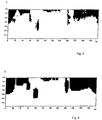
- a binarized matrix is shown by way of example, the binarized matrix covers the depth range T of from 2 m to 3.6 m and the full angle range w (from 0° to 360°).
- the logical value "1”, corresponding to areas which require repair, is represented in form of black areas and the logical value "0", corresponding to areas which do not require repair, is represented in form of white areas.
- FIG. 3 An example of a defragmented matrix of the identical cut-out is shown in Figure 3.
- This matrix has been created by comparing the binary values of a number of areas within a larger square section and determining whether the number of black areas within that section exceeds a ratio of 60 per cent. If the number exceeded the ratio of 60 per cent, then the whole area was assigned the binary value "1"; if the number did not exceed the ratio of 60 per cent, then the whole area was assigned the binary value "0". This procedure has been applied throughout the entire binarized matrix, and has been repeated 6 times, each time with increasing size of the enlarged sections.
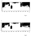
- Figure 4 illustrates the same matrix in a segmented form.
- the segment borderings are shown as lines around the fields having the binary value "1".
- the method employed for segmentation analyzed a multiplicity of adjacent series of fields in the defragmented matrix. If an adjacent series of fields having the binary value "1" has been found in the actually traversed line, the borderings thereof were determined. The so identified area was transformed to a regular rectangle and assigned a consecutive number.
- Figure 5 illustrates the sequence of the repair procedure, starting from area assigned consecutive number 1. The sequence has been determined under consideration that vertically adjacent areas are repaired from bottom to top, and that the whole distance to be travelled by the manipulator is minimal.
Abstract
Description
- The present invention relates to a method for repairing a protective lining of an industrial reaction or transport vessel, such as a converter vessel, electric arc furnace, or ladle, e.g. steel casting ladle, pig iron ladle, torpedo ladle or slag ladle. In particular, the present invention relates to a method for repairing a protective lining of an industrial reaction or transport vessel, wherein areas of the lining having a thickness below a pre-determined threshold value are identified and monolithic lining material is applied onto those areas.
- Industrial reaction or transport vessels, such as blast furnaces, electric arc furnaces, ladles or converters, are e.g. used for metallurgical purposes such as for producing steel. These vessels generally have a protective lining at their inner surface, which protects the outer metallic surface of the vessel from being damaged by the heat or reaction conditions inside the vessel. However, the protective lining is subjected to wear during the use of the vessels and must be repaired from time to time to ensure high operational safety.
- For this purpose, the residual thickness of the protective lining is measured between the individual phases of use of the vessel, when the vessel is empty. The residual thickness data obtained by this measurement are used to determine the areas of the lining which have to be repaired.
- International Patent Application WO 01/38900 A1 discloses a non-contacting measuring procedure for measuring the residual thickness of the refractory lining of a metallurgical vessel. The method comprises sweeping a laser beam from a measuring device over the inner surface of the metallurgical vessel, i.e. the surface of the refractory lining, and measuring the angle and the distance between measuring device and inner surface of the vessel at various points. The measuring device preferably includes a laser diode operating in a pulse mode as a transmitting device and a photodiode as a receiving device. The thus obtained data allow to image the surface structure of the refractory lining in the form of a three-dimensional thickness profile. WO 01/38900 A1 suggests that the measuring device is physically associated with a device which applies new lining material to the inside surface of the vessel.
- However, the lining material is generally applied manually to the inside surface of the vessel, either by means of an operator holding a repair device or by means of a repair device which is manually manipulated by an operator via a remote. In both cases the operator must be able to visibly identify the areas to be repaired and follow the movements of the repair device. Therefore, the operator has to be relatively close to the open-end of the vessel to be repaired. This is connected with several drawbacks. The operator is exposed to heat, fire, rebound of new lining material and other parts falling off the vessel. Furthermore, there is the danger of explosion in the vessels, if the hot material gets into contact with water, which may cause harm to the operator, if the operator is close to the vessel.
- Moreover, the manual method is inherently connected with human errors. For instance, if the operator misses the right spot to be repaired, e.g. by a few centimeters, there is the danger of causing a so called "breakthrough", which is a hole in the wall of the vessel, and may harm the operator of the vessel or damage the equipment connected with the vessel or even lead to explosions if the material flowing out of the vessel comes in contact with water. This may be a problem because it is difficult to visibly identify the areas to be repaired if the protective lining is entirely monolithic, and the operator can only obtain a rough guidance by the measurement of the thickness profile carried out before.
- If the operator actually holds the repair device, the output of new lining material is generally limited. Furthermore, because of the heat, repair time under control of an operator is generally limited to 10 to 15 minutes.
- Accordingly it would be highly desirable to provide a method for repairing a refractory lining of a metallurgical vessel which is more accurate than the methods according to the state of the art, using less material and which eliminates the operational dangers mentioned before.
- It is an object of the present invention to provide a method for repairing a monolithic lining of an industrial reaction or transport vessel which can be performed automatically, at high speed and high accuracy.
- It is another object of the present invention to provide a method for repairing a monolithic lining of an industrial reaction or transport vessel where the operational dangers are eliminated.
- It is a further object of the present invention to provide a method for repairing a monolithic lining of an industrial reaction or transport vessel which uses lining material more effectively.
- It is a still further object of the present invention to provide a method for repairing a monolithic lining of an industrial reaction or transport vessel which is easily adaptable to operational requirements.
- In its broadest aspect, the present invention provides a method for repairing a protective lining of an industrial reaction or transport vessel including the steps of
identifying areas of the lining having a thickness below a pre-determined threshold value by means of a measuring device, which measuring device measures the residual thickness of the lining and a processing unit, which processing unit in a first step transforms the residual thickness data into binary data, by comparing the measured residual thickness data with the pre-determined threshold value for the thickness of the lining, and assigning the binary value "1" to areas of the lining having a thickness below the pre-determined threshold value, and the binary value "0" to areas of the lining having a thickness equal or higher than the pre-determined threshold value, or vice versa, in a second step combines isolated areas of the lining having a thickness below the pre-determined threshold value into combined areas of the lining to which the binary value for areas of the lining having a thickness below the pre-determined threshold value is assigned, and in a third step computes the position and repair sequence of each of the combined areas and transfers these data to a repair device,
and applying monolithic lining material onto the combined areas computed by the processing unit by means of a repair device. - For actual performance of the repair, a repair device is provided which applies new lining material onto the damaged areas of the lining and which preferably includes a manipulator arm and a gunning nozzle which is disposed thereon and is rotatable, tiltable, vertically movable, and optionally horizontally movable. The position and operation of the repair device is controlled by a processing unit which transfers the actual residual thickness data obtained by means of the measuring device to the repair device in the form of repairing instructions. The processing unit is preferably electronically connected with both, the measuring device and the repair device.
- The present method includes number of processing steps for transferring the actual residual thickness data obtained by means of the measuring device to the repair device in the form of repair instructions. The residual thickness data are preferably sorted with reference to a regular grid which reflects the symmetry of the vessel. Since the preferred metallurgical vessels have a basic shape which substantially is in the form of a cylinder the residual thickness data are preferably converted into matrices and cylinder coordinates. If the vessel has a rectangular horizontal cross section, the residual thickness data are preferably converted into matrices and cartesian coordinates.
- The processing steps include transforming the residual thickness data into binary data, by comparing the residual thickness data with the pre-determined threshold value for the thickness of the lining, and e.g. assigning the binary value "1" to areas of the lining having a thickness below the pre-determined threshold value, and the binary value "0" to areas of the lining having a thickness equal or higher than the pre-determined threshold value, hereinafter referred to as "binarization".
- To reduce the amount of data to be processed, before binarization, the three-dimensional residual-thickness data obtained by the measuring device of a number of points in the vessel may preferably be averaged in the processing unit, in a first processing step referred to as "averaging".
- After binarization, isolated areas of the lining having a thickness below the pre-determined threshold value are combined into adjacent combined areas of the lining to which the binary value for areas of the lining having a thickness below the pre-determined threshold value is assigned, which processing step is hereinafter referred to as "defragmentation". For achieving this, the binary values of a number of areas are preferably compared with each other, and, if the number of areas of the lining having a thickness below the pre-determined threshold value exceeds a pre-selected ratio, the whole compared area is assigned the binary value for areas having a thickness below the pre-determined threshold value. Thereby the fact is accepted that areas of the lining having a thickness equal or higher than the pre-determined threshold value adjacent to areas of the lining having a thickness below the pre-determined threshold value will be sprayed on with new lining material as well, although these areas do not require a repair yet. A preferred ratio is e.g. from about 30 per cent to about 80 per cent, most preferably from about 50 per cent to about 60 per cent.
- The defragmentation can be carried out using different degrees of defragmentation. Preferably, the degree of defragmentation is varied as a function of the production-related boundary conditions such as the uniformity in reconstituting the refractory lining, mass of the relining compound, and time of repair.
- Finally, the position and repair sequence of each of the combined areas is computed and converted into repair instructions for the repair device in a further processing step. Therefore, each computed area having the binary value for areas having a thickness below the pre-determined threshold value is associated with a consecutive number representing the sequence of steps of application of monolithic lining material. This processing step is hereinafter referred to as "sequencing". The sequence is preferably selected, taking into account the static characteristics and the curing behavior of the repair material that is applied onto the inner surface of the monolithic lining, in particular the curing time of the repair material. In particular, the preferred sequence takes into account that the refractory lining has to be repaired from the lower sections of the metallurgical vessel to its upper sections. Thereby the repair material, if applied in form of horizontal strips to the repair areas, is supported by the relining compound applied in adjacent lower sections before.
- In a particularly preferred aspect of the invention, the residual-thickness data are processed to obtain repair data in such a way that the shape of each area to be repaired, as seen towards the surface of the refractory lining, is enlarged into a simple geometrical basic shape, preferably a rectangle. Thereby the working speed of the repair device may be further increased.
- In a further particularly preferred aspect of the invention, the orientation and form of the geometrical basic shape is adapted, in the processing unit, to the existing axes of motion of the repair device, which is preferably a spraying, a gunning or a shotcreting device and the like. With this adaptation the repair device can be moved along its existing axes of motion in order to perform the repair of the refractory lining. Thereby the working speed of the repair device is increased and the repair device is easier to control. This processing step is preferably carried out after defragmentation, and is hereinafter referred to as "segmentation".
- In a further preferred aspect of the present invention, prior to determining the sequence of steps of application of monolithic lining material, the steps of binarization, defragmentation, and optionally segmentation are carried out again under variation of the threshold value, so that deeper holes may be repaired in multiple repair steps by applying a multiplicity of layers of monolithic lining material.
- In a still further, particularly preferred aspect, prior to a transfer of the repair data to the repair device, the result of the repair is represented in the processing unit by means of a simulation under consideration of specific operational parameters such as the time of repair, and amount of the repair compound. Thus, the operator of the processing unit may easily adapt the repair procedure to varying conditions.
- It is particularly preferred that, after completion of the spraying step, the residual thickness of the refractory lining is once again measured by the measuring device and the thus obtained residual thickness data are compared with data obtained by a simulation regarding the achievable reconstitution of the refractory lining, and in case of a deviation between the newly measured residual thickness data and the simulation data, the control unit of the repair device is calibrated accordingly. Alternatively, a further repair step may be started.
- The invention will be exemplary described below in more detail with reference to the attached figures, wherein
- Fig. 1
- shows a schematic view of a metallurgical vessel formed as an electric arc furnace, a measuring device for wear determination and a gunning device for repairing the refractory lining,
- Fig. 2
- shows a cut-out of the binarized matrix reflecting the refractory lining of an electric arc furnace,
- Fig. 3
- shows a cut-out of the defragmented matrix of the refractory lining of an electric arc furnace,
- Fig. 4
- shows a cut-out of the segmented matrix of the refractory lining of an electric arc furnace, and
- Fig. 5
- shows a cut-out of the sequenced matrix of the refractory lining of an electric arc furnace.
- In particular, Figure 1 shows a schematic view of a
metallurgical vessel 1 formed as an arc furnace with arefractory lining 2 which requires a repair. Arepair device 3 is provided for the repair of thelining 2 and is formed as a gunning device having a gunninghead 4 and amanipulator 5. The gunning device pneumatically conveys a dry refractory mix through anozzle 4b of the gunninghead 4 and at thenozzle 4b water will be added to the refractory mix. It is also possible that the repair device is a shotcreting device. In contrast to the aforementioned gunning device the shotcreting device conveys a wet refractory mix through the shotcreting head with air and a reactive compound added to the wet refractory mix at thenozzle 4b.Manipulator 5 substantially includes astationary column 5a rotatable about a vertical axis to the upper end of which anangular extension arm 5b is hinged. Gunninghead 4 is suspended at the end ofangular extension arm 5b facing away fromcolumn 5a.Extension arm 5b is pivotally supported about a horizontal axis at the upper end ofcolumn 5a. Gunninghead 4 is pivotally supported about another axis which is substantially vertical and runs in parallel with thecolumn 5a. Furthermore, gunninghead 4 has a gunningarm 4a with anozzle 4b that is pivotally mounted on gunninghead 4. Thus,repair device 3 has four rotatory freedom degrees to allow a travel to the individual areas requiring a repair withinmetallurgical vessel 1. Drives (not shown) which are triggered via acontrol unit 6 for the repair procedure are provided to carry out the single rotational and pivotal motions ofrepair device 3. The control data referred to as repair data to perform the repair procedure are received bycontrol unit 6 from aprocessing unit 7 which evaluates and processes relevant information from a measuringdevice 8. Measuringdevice 8 serves for determining the wear ofrefractory lining 2 and substantially includes a laser working in a non-contacting manner. For the measuringprocedure measuring device 8, disposed at a free-end of acarrier arm 9, is moved over the opening 10 of the hotmetallurgical vessel 1. - The residual thickness data determined by measuring
device 8 are transferred from measuringdevice 8 to aprocessing unit 7. Theprocessing unit 7 carries out the steps described herein before to process the residual thickness data received from the measuringdevice 8 into repair instructions for therepair device 3. - In Figure 2, a binarized matrix is shown by way of example, the binarized matrix covers the depth range T of from 2 m to 3.6 m and the full angle range w (from 0° to 360°). The logical value "1", corresponding to areas which require repair, is represented in form of black areas and the logical value "0", corresponding to areas which do not require repair, is represented in form of white areas.
- An example of a defragmented matrix of the identical cut-out is shown in Figure 3. This matrix has been created by comparing the binary values of a number of areas within a larger square section and determining whether the number of black areas within that section exceeds a ratio of 60 per cent. If the number exceeded the ratio of 60 per cent, then the whole area was assigned the binary value "1"; if the number did not exceed the ratio of 60 per cent, then the whole area was assigned the binary value "0". This procedure has been applied throughout the entire binarized matrix, and has been repeated 6 times, each time with increasing size of the enlarged sections.
- Figure 4 illustrates the same matrix in a segmented form. The segment borderings are shown as lines around the fields having the binary value "1". The method employed for segmentation analyzed a multiplicity of adjacent series of fields in the defragmented matrix. If an adjacent series of fields having the binary value "1" has been found in the actually traversed line, the borderings thereof were determined. The so identified area was transformed to a regular rectangle and assigned a consecutive number.
- Figure 5 illustrates the sequence of the repair procedure, starting from area assigned
consecutive number 1. The sequence has been determined under consideration that vertically adjacent areas are repaired from bottom to top, and that the whole distance to be travelled by the manipulator is minimal.
Claims (15)
- A method for repairing a protective lining of an industrial reaction or transport vessel including the steps of identifying areas of the lining having a thickness below a pre-determined threshold value by means of a measuring device, which measuring device measures the residual thickness of the lining and a processing unit, which processing unit in a first step transforms the residual thickness data into binary data, by comparing the measured residual thickness data with the pre-determined threshold value for the thickness of the lining, and assigning the binary value "1" to areas of the lining having a thickness below the pre-determined threshold value, and the binary value "0" to areas of the lining having a thickness equal or higher than the pre-determined threshold value, or vice versa, in a second step combines isolated areas of the lining having a thickness below the pre-determined threshold value into combined areas of the lining to which the binary value for areas of the lining having a thickness below the pre-determined threshold value is assigned, and in a third step computes the position and repair sequence of each of the combined areas and transfers these data to a repair device, and applying monolithic lining material onto the combined areas computed by the processing unit by means of a repair device.
- The method of claim 1, wherein the protective lining is a refractory lining.
- The method of any one claims 1 or 2, wherein the industrial reaction or transport vessel is a metallurgical vessel.
- The method of claim 3, wherein the metallurgical vessel is selected from a converter vessel, an electric arc furnace, a blast furnace, a ladle, a tundish and a coke oven chamber.
- The method of claim 4, wherein the ladle is selected from a steel casting ladle, pig iron ladle, torpedo ladle and slag ladle.
- The method of any one of the preceding claims, wherein the measuring device is a laser-based measuring device.
- The method of claim 6, wherein the laser-based measuring device is a mirror scanner.
- The method of any one of the preceding claims, wherein the repair device comprises a manipulator arm and a gunning nozzle which is disposed thereon and is rotatable, tiltable and vertically movable.
- The method of any one of the preceding claims, wherein the repair device is selected from a spraying, a gunning and a shotcreting device.
- The method of any one of the preceding claims, wherein the processing unit is electronically connected with the measuring device and the repair device.
- The method of any one of the preceding claims, wherein steps within the processing unit are carried out electronically.
- The method of any one of the preceding claims, wherein the processing unit combines the isolated spots into rectangular combined areas.
- The method of any one of the preceding claims, wherein the position of each of the combined areas are computed in the form of cyclinder coordinates.
- The method of any one of the preceding claims, wherein the residual thickness of the refractory lining is once again measured by the measuring device, after completion of the repair step and the thus obtained residual thickness data are compared with data obtained by a simulation regarding the achievable reconstitution of the refractory lining, and in case of a deviation between the newly measured residual thickness data and the simulation data, the control unit of the repair device is calibrated accordingly.
- The method of any one of the preceding claims, wherein the residual thickness of the refractory lining is once again measured by the measuring device, after completion of the repair step and the thus obtained residual thickness data are compared with data obtained by a simulation regarding the achievable reconstitution of the refractory lining, and in case of a deviation between the newly measured residual thickness data and the simulation data, the processing and repair sequence is repeated.
Applications Claiming Priority (3)
| Application Number | Priority Date | Filing Date | Title |
|---|---|---|---|
| DE10223284A DE10223284A1 (en) | 2002-05-24 | 2002-05-24 | Process for repairing a protective lining of an industrial reaction or transport vessel |
| DE10223284 | 2002-05-24 | ||
| PCT/EP2003/005332 WO2003100336A1 (en) | 2002-05-24 | 2003-05-21 | A method for repairing a protective lining of an industrial reaction or transport vessel |
Publications (2)
| Publication Number | Publication Date |
|---|---|
| EP1508012A1 EP1508012A1 (en) | 2005-02-23 |
| EP1508012B1 true EP1508012B1 (en) | 2005-09-21 |
Family
ID=29432301
Family Applications (1)
| Application Number | Title | Priority Date | Filing Date |
|---|---|---|---|
| EP03755110A Expired - Lifetime EP1508012B1 (en) | 2002-05-24 | 2003-05-21 | A method for repairing a protective lining of an industrial reaction or transport vessel |
Country Status (23)
| Country | Link |
|---|---|
| US (1) | US8083982B2 (en) |
| EP (1) | EP1508012B1 (en) |
| JP (1) | JP4417248B2 (en) |
| CN (1) | CN100458341C (en) |
| AR (1) | AR040100A1 (en) |
| AT (1) | ATE305124T1 (en) |
| AU (1) | AU2003232810A1 (en) |
| BR (1) | BR0310075A (en) |
| CA (1) | CA2483641C (en) |
| DE (2) | DE10223284A1 (en) |
| DK (1) | DK1508012T3 (en) |
| ES (1) | ES2244945T3 (en) |
| HK (1) | HK1069204A1 (en) |
| IL (1) | IL164792A0 (en) |
| MX (1) | MXPA04011620A (en) |
| NO (1) | NO20044907L (en) |
| PL (1) | PL372767A1 (en) |
| RU (1) | RU2303223C2 (en) |
| SA (1) | SA03240225B1 (en) |
| TW (1) | TWI226926B (en) |
| UA (1) | UA79785C2 (en) |
| WO (1) | WO2003100336A1 (en) |
| ZA (1) | ZA200408574B (en) |
Families Citing this family (18)
| Publication number | Priority date | Publication date | Assignee | Title |
|---|---|---|---|---|
| BRPI0520370B8 (en) | 2005-06-28 | 2023-01-31 | Scanalyse Pty Ltd | SYSTEM AND METHOD FOR MEASURING AND MAPPING A SURFACE IN RELATION TO A REFERENCE |
| DE102006013185A1 (en) * | 2006-03-22 | 2007-09-27 | Refractory Intellectual Property Gmbh & Co. Kg | Method for determining the position and orientation of a measuring or repair device and a device operating according to the method |
| US10378891B2 (en) | 2007-12-28 | 2019-08-13 | Outotec Pty Ltd | System and method for measuring and mapping a surface relative to a reference |
| WO2011027610A1 (en) | 2009-09-02 | 2011-03-10 | 新日鉄エンジニアリング株式会社 | Method of demolishing furnace of multilayered-refractory structure |
| US20120217357A1 (en) * | 2009-09-09 | 2012-08-30 | Jochen Franke | System and method for monitoring condition of surface subject to wear |
| US8072613B2 (en) * | 2010-03-25 | 2011-12-06 | Specialty Minerals (Michigan) Inc. | System for measuring the inner space of a container and method of performing the same |
| RU2421274C1 (en) * | 2010-03-29 | 2011-06-20 | Открытое Акционерное Общество "Научно-Исследовательский И Проектный Институт Карбамида И Продуктов Органического Синтеза" (Оао Ниик) | Lining repair device |
| TWI480512B (en) * | 2013-04-17 | 2015-04-11 | China Steel Corp | The method of obtaining the best position of blast furnace wall blast furnace |
| CN103447515B (en) * | 2013-08-29 | 2017-09-15 | 鞍钢股份有限公司 | Online hot repair method during a kind of basket pouring |
| CN104567415B (en) * | 2015-01-15 | 2016-07-27 | 江西稀有稀土金属钨业集团有限公司 | The electronic cupola drop instrument of vaccum sensitive stove etc. |
| CN104833205B (en) * | 2015-05-23 | 2016-11-30 | 石家庄新华能源环保科技股份有限公司 | The method of liner mended by a kind of rotary kiln |
| WO2019226125A1 (en) * | 2018-05-23 | 2019-11-28 | Pi̇romet Pi̇rometalurji̇ Malzeme Refrakter Maki̇na Sanayi̇ Ve Ti̇caret Anoni̇m Şi̇rketi̇ | Fully automatic refractory spraying robot with measurement system |
| WO2020196527A1 (en) * | 2019-03-26 | 2020-10-01 | Jfeスチール株式会社 | Inspection device and inspection method upon construction of coke oven, and coke oven construction method |
| CN110321751B (en) * | 2019-04-29 | 2020-05-08 | 北京科技大学 | Steel ladle number identification method |
| CN110184500B (en) * | 2019-07-03 | 2020-11-03 | 辽宁思达思克控股有限公司 | Powder and method for laser remanufacturing of junction surface of upper supporting plate and supporting ring of converter |
| US10859316B1 (en) | 2019-09-26 | 2020-12-08 | Harbisonwalker International, Inc. | Predictive refractory performance measurement system |
| US11237124B2 (en) | 2019-09-26 | 2022-02-01 | Harbisonwalker International, Inc. | Predictive refractory performance measurement system |
| JP7447860B2 (en) | 2021-04-20 | 2024-03-12 | Jfeスチール株式会社 | Repair system and method |
Family Cites Families (27)
| Publication number | Priority date | Publication date | Assignee | Title |
|---|---|---|---|---|
| US3469030A (en) * | 1965-11-19 | 1969-09-23 | North American Rockwell | Optical scanner utilizing a spherical mirror |
| NL7008651A (en) * | 1970-06-12 | 1970-08-25 | Koninklijke Hoogovens En Staal | |
| US3827633A (en) * | 1972-08-25 | 1974-08-06 | Kurosaki Refractories Co | Mobile device for repairing furnace walls and the like |
| US3917170A (en) * | 1974-07-19 | 1975-11-04 | Quigley Co | Mobile refractory gunning apparatus |
| JPS5816121B2 (en) | 1974-09-03 | 1983-03-29 | 住友金属工業株式会社 | Reiki Yakubakono Sonmousoku Teihouhou |
| SE414347B (en) * | 1974-11-20 | 1980-07-21 | Aga Ab | DEVICE FOR MEASURING THE DISTANCE TO A POINT ON THE OWN RANGE INNER WALL IN A OVEN |
| JPS51147510A (en) * | 1975-06-13 | 1976-12-17 | Nippon Steel Corp | Method of measuring working surface profile of refractory lining vessels and of mending the surface |
| US4272018A (en) * | 1978-08-04 | 1981-06-09 | Southern Refractories, Inc. | Apparatus and method for spraying refractory material |
| US5127736A (en) * | 1982-02-22 | 1992-07-07 | Armco Inc. | Apparatus for measuring wear in the lining of refractory furnaces |
| EP0121617A1 (en) * | 1983-04-07 | 1984-10-17 | Armco Inc. | Method and apparatus for measuring wear in the lining of refractory furnaces |
| US4541971A (en) * | 1983-04-28 | 1985-09-17 | Masaru Takashima | Method for the gunning of refractories |
| JPH065155B2 (en) | 1984-10-12 | 1994-01-19 | 住友金属工業株式会社 | Furnace wall repair device for kiln |
| LU85836A1 (en) * | 1985-04-03 | 1986-11-05 | Wurth Paul Sa | INSTALLATION FOR THE INSTALLATION OF A REFRACTORY TRIM ON THE INTERIOR WALL OF AN ENCLOSURE |
| US4690328A (en) * | 1985-08-05 | 1987-09-01 | Bentonspritz Nascgubeb Gmbh Co. | Spraying machine |
| CN85106445A (en) * | 1985-08-27 | 1987-03-18 | 斯蒂芬·帕斯克和西公司 | Be used for repairing the equipment of the blast furnace of being with rotary hopper and use this equipment to repair the method for blast furnace |
| US4860422A (en) * | 1987-10-01 | 1989-08-29 | Quigley Company, Inc. | Rebuilding of the stack, bosh and hearth of a blast furnace using a remote controlled refractory gunning device |
| NL8702891A (en) * | 1987-12-02 | 1989-07-03 | Hoogovens Groep Bv | METHOD FOR REPAIRING THE FIRE-RESISTANT COATING OF THE WALL OF A SHAFT OVEN, AND SHAFT OVEN REPAIRED BY THIS METHOD |
| SU1632978A1 (en) | 1989-01-02 | 1991-03-07 | Днепропетровский Металлургический Институт | Device for monitoring wear of lining |
| US5178329A (en) * | 1989-05-05 | 1993-01-12 | Quigley Inc. | Remote controlled refractory gunning apparatus |
| US5212738A (en) | 1991-04-12 | 1993-05-18 | Martin Marietta Magnesia Specialties Inc. | Scanning laser measurement system |
| DE69307158T2 (en) * | 1992-02-07 | 1997-04-17 | Nippon Steel Corp | Method and device for determining the thickness of the refractory coating in a container for molten metal and for detecting penetrating metal in the coating |
| GB9311686D0 (en) * | 1993-06-05 | 1993-07-21 | Monocon Int Ltd | Vessel repair |
| JPH07248192A (en) * | 1994-03-11 | 1995-09-26 | Harima Ceramic Co Ltd | Equipment for observation and repair of inside of high temperature furnace |
| US5419922A (en) * | 1994-03-15 | 1995-05-30 | Bmi, Inc. | Method and apparatus for repairing the refractory lining of a refractory vessel |
| US5792393A (en) * | 1997-03-25 | 1998-08-11 | Atlantic Richfield Company | Method of repairing hot refractory linings in high-temperature vessels |
| US6034345A (en) * | 1998-01-28 | 2000-03-07 | Hot Tech Inc. | Apparatus for repairing high temperature process vessels |
| US6780351B2 (en) * | 2001-04-30 | 2004-08-24 | Emil J. Wirth, Jr. | Vessel inspection and repair system |
-
2002
- 2002-05-24 DE DE10223284A patent/DE10223284A1/en not_active Ceased
-
2003
- 2003-05-21 WO PCT/EP2003/005332 patent/WO2003100336A1/en active IP Right Grant
- 2003-05-21 UA UA20041209897A patent/UA79785C2/en unknown
- 2003-05-21 DE DE60301671T patent/DE60301671T2/en not_active Expired - Lifetime
- 2003-05-21 EP EP03755110A patent/EP1508012B1/en not_active Expired - Lifetime
- 2003-05-21 AT AT03755110T patent/ATE305124T1/en not_active IP Right Cessation
- 2003-05-21 CA CA2483641A patent/CA2483641C/en not_active Expired - Lifetime
- 2003-05-21 AU AU2003232810A patent/AU2003232810A1/en not_active Abandoned
- 2003-05-21 US US10/525,686 patent/US8083982B2/en active Active
- 2003-05-21 IL IL16479203A patent/IL164792A0/en unknown
- 2003-05-21 JP JP2004507750A patent/JP4417248B2/en not_active Expired - Lifetime
- 2003-05-21 RU RU2004137822/02A patent/RU2303223C2/en active
- 2003-05-21 BR BR0310075-8A patent/BR0310075A/en active Search and Examination
- 2003-05-21 PL PL03372767A patent/PL372767A1/en not_active IP Right Cessation
- 2003-05-21 ES ES03755110T patent/ES2244945T3/en not_active Expired - Lifetime
- 2003-05-21 DK DK03755110T patent/DK1508012T3/en active
- 2003-05-21 CN CNB038118254A patent/CN100458341C/en not_active Expired - Fee Related
- 2003-05-21 MX MXPA04011620A patent/MXPA04011620A/en not_active Application Discontinuation
- 2003-05-23 TW TW092114019A patent/TWI226926B/en not_active IP Right Cessation
- 2003-05-23 AR ARP030101823A patent/AR040100A1/en unknown
- 2003-08-05 SA SA03240225A patent/SA03240225B1/en unknown
-
2004
- 2004-10-22 ZA ZA2004/08574A patent/ZA200408574B/en unknown
- 2004-11-10 NO NO20044907A patent/NO20044907L/en not_active Application Discontinuation
-
2005
- 2005-03-24 HK HK05102572A patent/HK1069204A1/en not_active IP Right Cessation
Also Published As
| Publication number | Publication date |
|---|---|
| IL164792A0 (en) | 2005-12-18 |
| RU2303223C2 (en) | 2007-07-20 |
| BR0310075A (en) | 2005-02-22 |
| SA03240225B1 (en) | 2007-07-31 |
| AU2003232810A1 (en) | 2003-12-12 |
| ATE305124T1 (en) | 2005-10-15 |
| HK1069204A1 (en) | 2005-05-13 |
| DE60301671D1 (en) | 2006-02-02 |
| CA2483641C (en) | 2011-04-19 |
| UA79785C2 (en) | 2007-07-25 |
| WO2003100336A1 (en) | 2003-12-04 |
| PL372767A1 (en) | 2005-08-08 |
| US20050263945A1 (en) | 2005-12-01 |
| ZA200408574B (en) | 2005-12-28 |
| ES2244945T3 (en) | 2005-12-16 |
| CN100458341C (en) | 2009-02-04 |
| EP1508012A1 (en) | 2005-02-23 |
| MXPA04011620A (en) | 2005-03-07 |
| TWI226926B (en) | 2005-01-21 |
| DE10223284A1 (en) | 2003-12-11 |
| US8083982B2 (en) | 2011-12-27 |
| RU2004137822A (en) | 2005-09-27 |
| CA2483641A1 (en) | 2003-12-04 |
| DE60301671T2 (en) | 2006-07-13 |
| AR040100A1 (en) | 2005-03-16 |
| CN1656350A (en) | 2005-08-17 |
| JP4417248B2 (en) | 2010-02-17 |
| TW200401875A (en) | 2004-02-01 |
| DK1508012T3 (en) | 2006-02-06 |
| JP2005526948A (en) | 2005-09-08 |
| NO20044907L (en) | 2004-11-10 |
Similar Documents
| Publication | Publication Date | Title |
|---|---|---|
| EP1508012B1 (en) | A method for repairing a protective lining of an industrial reaction or transport vessel | |
| US4893933A (en) | Automatic BOF vessel remaining lining profiler and method | |
| EP2558816B1 (en) | System for measuring the inner space of a container and method of performing the same | |
| EP1960734B1 (en) | Method for measuring wear in the refractory lining of a metallurgical melting vessel | |
| JPS6193384A (en) | Repair device for kiln furnace of kiln | |
| NZ536148A (en) | A method for repairing a protective lining of an industrial reaction or transport vessel | |
| JP2022538021A (en) | Systems, devices and methods for measuring internal refractory linings of vessels | |
| Sawai et al. | Methods of evaluating the damage of steelmaking refractories | |
| JP6848652B2 (en) | Converter refractory profile measuring device and converter refractory profile measuring method | |
| JPH0920906A (en) | Method for measuring profile of furnace wall of blast furnace and its instrument | |
| JPH0972852A (en) | Detection method for crack of lining refractory in molten-metal receiver container and repair method for crack | |
| JP2819229B2 (en) | Repair method of coke oven wall | |
| RU221616U1 (en) | Manipulator for gunning of industrial equipment | |
| JP7472890B2 (en) | Repair management method and repair management system | |
| JPH06145742A (en) | Device for hot-repairing large trough in blast furnace and method therefor | |
| JP7444130B2 (en) | Repair system and method | |
| JPH0384393A (en) | Measuring device for thickness of side walls for ladle | |
| EP3892956A1 (en) | Method and system for monitoring a refractory lining of a vessel | |
| JPH05256584A (en) | Method and apparatus for repairing damaged part on furnace wall in melting furnace | |
| JP2022165865A (en) | Repair system and repair method | |
| JPH07268425A (en) | Hot repair device for large trough of blast furnace | |
| JPH09235606A (en) | Method for measuring profile of inner wall of blast furnace | |
| ES1300941U (en) | INSTALLATION, ROBOT AND HEAD TO SPRAY A PRODUCT INSIDE A CONTAINER SUITABLE FOR CONTAINING MOLTEN METAL (Machine-translation by Google Translate, not legally binding) | |
| ES1301002U (en) | INSTALLATION, ROBOT AND HEAD TO SPRAY A PRODUCT INSIDE A SUITABLE CONTAINER TO CONTAIN MOLTEN METAL (Machine-translation by Google Translate, not legally binding) | |
| JPH06116611A (en) | Device and method for hot-repairing large trough in blast furnace |
Legal Events
| Date | Code | Title | Description |
|---|---|---|---|
| PUAI | Public reference made under article 153(3) epc to a published international application that has entered the european phase |
Free format text: ORIGINAL CODE: 0009012 |
|
| 17P | Request for examination filed |
Effective date: 20041109 |
|
| AK | Designated contracting states |
Kind code of ref document: A1 Designated state(s): AT BE BG CH CY CZ DE DK EE ES FI FR GB GR HU IE IT LI LU MC NL PT RO SE SI SK TR |
|
| RAP1 | Party data changed (applicant data changed or rights of an application transferred) |
Owner name: SPECIALTY MINERALS (MICHIGAN) INC. |
|
| GRAP | Despatch of communication of intention to grant a patent |
Free format text: ORIGINAL CODE: EPIDOSNIGR1 |
|
| RIN1 | Information on inventor provided before grant (corrected) |
Inventor name: KIRCHHOFF, STEFAN Inventor name: BLISSENBACH, DIETER Inventor name: LAMM, ROLF |
|
| RAP1 | Party data changed (applicant data changed or rights of an application transferred) |
Owner name: SPECIALTY MINERALS (MICHIGAN) INC. |
|
| REG | Reference to a national code |
Ref country code: HK Ref legal event code: DE Ref document number: 1069204 Country of ref document: HK |
|
| GRAS | Grant fee paid |
Free format text: ORIGINAL CODE: EPIDOSNIGR3 |
|
| GRAA | (expected) grant |
Free format text: ORIGINAL CODE: 0009210 |
|
| AK | Designated contracting states |
Kind code of ref document: B1 Designated state(s): AT BE BG CH CY CZ DE DK EE ES FI FR GB GR HU IE IT LI LU MC NL PT RO SE SI SK TR |
|
| PG25 | Lapsed in a contracting state [announced via postgrant information from national office to epo] |
Ref country code: RO Free format text: LAPSE BECAUSE OF FAILURE TO SUBMIT A TRANSLATION OF THE DESCRIPTION OR TO PAY THE FEE WITHIN THE PRESCRIBED TIME-LIMIT Effective date: 20050921 Ref country code: SI Free format text: LAPSE BECAUSE OF FAILURE TO SUBMIT A TRANSLATION OF THE DESCRIPTION OR TO PAY THE FEE WITHIN THE PRESCRIBED TIME-LIMIT Effective date: 20050921 |
|
| REG | Reference to a national code |
Ref country code: GB Ref legal event code: FG4D |
|
| REG | Reference to a national code |
Ref country code: CH Ref legal event code: EP |
|
| REG | Reference to a national code |
Ref country code: IE Ref legal event code: FG4D |
|
| REF | Corresponds to: |
Ref document number: 60301671 Country of ref document: DE Date of ref document: 20051027 Kind code of ref document: P |
|
| REG | Reference to a national code |
Ref country code: HK Ref legal event code: GR Ref document number: 1069204 Country of ref document: HK |
|
| REG | Reference to a national code |
Ref country code: ES Ref legal event code: FG2A Ref document number: 2244945 Country of ref document: ES Kind code of ref document: T3 |
|
| PG25 | Lapsed in a contracting state [announced via postgrant information from national office to epo] |
Ref country code: BG Free format text: LAPSE BECAUSE OF FAILURE TO SUBMIT A TRANSLATION OF THE DESCRIPTION OR TO PAY THE FEE WITHIN THE PRESCRIBED TIME-LIMIT Effective date: 20051221 |
|
| REG | Reference to a national code |
Ref country code: SE Ref legal event code: TRGR |
|
| REG | Reference to a national code |
Ref country code: GR Ref legal event code: EP Ref document number: 20050403649 Country of ref document: GR |
|
| REF | Corresponds to: |
Ref document number: 60301671 Country of ref document: DE Date of ref document: 20060202 Kind code of ref document: P |
|
| REG | Reference to a national code |
Ref country code: DK Ref legal event code: T3 |
|
| ET | Fr: translation filed | ||
| PG25 | Lapsed in a contracting state [announced via postgrant information from national office to epo] |
Ref country code: IE Free format text: LAPSE BECAUSE OF NON-PAYMENT OF DUE FEES Effective date: 20060522 Ref country code: HU Free format text: LAPSE BECAUSE OF NON-PAYMENT OF DUE FEES Effective date: 20060522 |
|
| PG25 | Lapsed in a contracting state [announced via postgrant information from national office to epo] |
Ref country code: MC Free format text: LAPSE BECAUSE OF NON-PAYMENT OF DUE FEES Effective date: 20060531 Ref country code: DK Free format text: LAPSE BECAUSE OF NON-PAYMENT OF DUE FEES Effective date: 20060531 |
|
| PLBE | No opposition filed within time limit |
Free format text: ORIGINAL CODE: 0009261 |
|
| STAA | Information on the status of an ep patent application or granted ep patent |
Free format text: STATUS: NO OPPOSITION FILED WITHIN TIME LIMIT |
|
| 26N | No opposition filed |
Effective date: 20060622 |
|
| REG | Reference to a national code |
Ref country code: DK Ref legal event code: EBP |
|
| PG25 | Lapsed in a contracting state [announced via postgrant information from national office to epo] |
Ref country code: PT Free format text: LAPSE BECAUSE OF NON-PAYMENT OF DUE FEES Effective date: 20070221 |
|
| REG | Reference to a national code |
Ref country code: IE Ref legal event code: MM4A |
|
| REG | Reference to a national code |
Ref country code: PT Ref legal event code: MM4A Free format text: LAPSE DUE TO NON-PAYMENT OF FEES Effective date: 20070221 |
|
| PGFP | Annual fee paid to national office [announced via postgrant information from national office to epo] |
Ref country code: NL Payment date: 20070412 Year of fee payment: 5 |
|
| PGFP | Annual fee paid to national office [announced via postgrant information from national office to epo] |
Ref country code: SK Payment date: 20070423 Year of fee payment: 5 |
|
| PGFP | Annual fee paid to national office [announced via postgrant information from national office to epo] |
Ref country code: CZ Payment date: 20070426 Year of fee payment: 5 |
|
| PGFP | Annual fee paid to national office [announced via postgrant information from national office to epo] |
Ref country code: CH Payment date: 20070427 Year of fee payment: 5 |
|
| REG | Reference to a national code |
Ref country code: CH Ref legal event code: PFA Owner name: SPECIALTY MINERALS (MICHIGAN) INC. Free format text: SPECIALTY MINERALS (MICHIGAN) INC.#30600 TELEGRAPH ROAD#BINGHAM FARMS, MICHIGAN 48025 (US) -TRANSFER TO- SPECIALTY MINERALS (MICHIGAN) INC.#30600 TELEGRAPH ROAD#BINGHAM FARMS, MICHIGAN 48025 (US) |
|
| PGFP | Annual fee paid to national office [announced via postgrant information from national office to epo] |
Ref country code: GR Payment date: 20070419 Year of fee payment: 5 |
|
| PG25 | Lapsed in a contracting state [announced via postgrant information from national office to epo] |
Ref country code: EE Free format text: LAPSE BECAUSE OF FAILURE TO SUBMIT A TRANSLATION OF THE DESCRIPTION OR TO PAY THE FEE WITHIN THE PRESCRIBED TIME-LIMIT Effective date: 20050921 |
|
| PGFP | Annual fee paid to national office [announced via postgrant information from national office to epo] |
Ref country code: LU Payment date: 20080508 Year of fee payment: 6 |
|
| PG25 | Lapsed in a contracting state [announced via postgrant information from national office to epo] |
Ref country code: CY Free format text: LAPSE BECAUSE OF FAILURE TO SUBMIT A TRANSLATION OF THE DESCRIPTION OR TO PAY THE FEE WITHIN THE PRESCRIBED TIME-LIMIT Effective date: 20050921 |
|
| REG | Reference to a national code |
Ref country code: CH Ref legal event code: PL |
|
| PG25 | Lapsed in a contracting state [announced via postgrant information from national office to epo] |
Ref country code: NL Free format text: LAPSE BECAUSE OF NON-PAYMENT OF DUE FEES Effective date: 20081201 Ref country code: LI Free format text: LAPSE BECAUSE OF NON-PAYMENT OF DUE FEES Effective date: 20080531 Ref country code: CH Free format text: LAPSE BECAUSE OF NON-PAYMENT OF DUE FEES Effective date: 20080531 |
|
| PG25 | Lapsed in a contracting state [announced via postgrant information from national office to epo] |
Ref country code: SK Free format text: LAPSE BECAUSE OF NON-PAYMENT OF DUE FEES Effective date: 20080521 |
|
| PG25 | Lapsed in a contracting state [announced via postgrant information from national office to epo] |
Ref country code: CZ Free format text: LAPSE BECAUSE OF NON-PAYMENT OF DUE FEES Effective date: 20080521 |
|
| PG25 | Lapsed in a contracting state [announced via postgrant information from national office to epo] |
Ref country code: GR Free format text: LAPSE BECAUSE OF NON-PAYMENT OF DUE FEES Effective date: 20081204 |
|
| PGFP | Annual fee paid to national office [announced via postgrant information from national office to epo] |
Ref country code: FI Payment date: 20090518 Year of fee payment: 7 Ref country code: IT Payment date: 20090521 Year of fee payment: 7 Ref country code: SE Payment date: 20090507 Year of fee payment: 7 |
|
| PGFP | Annual fee paid to national office [announced via postgrant information from national office to epo] |
Ref country code: AT Payment date: 20100407 Year of fee payment: 8 |
|
| PG25 | Lapsed in a contracting state [announced via postgrant information from national office to epo] |
Ref country code: FI Free format text: LAPSE BECAUSE OF NON-PAYMENT OF DUE FEES Effective date: 20100521 |
|
| EUG | Se: european patent has lapsed | ||
| PG25 | Lapsed in a contracting state [announced via postgrant information from national office to epo] |
Ref country code: SE Free format text: LAPSE BECAUSE OF NON-PAYMENT OF DUE FEES Effective date: 20100522 Ref country code: IT Free format text: LAPSE BECAUSE OF NON-PAYMENT OF DUE FEES Effective date: 20100521 |
|
| PG25 | Lapsed in a contracting state [announced via postgrant information from national office to epo] |
Ref country code: LU Free format text: LAPSE BECAUSE OF NON-PAYMENT OF DUE FEES Effective date: 20090521 |
|
| REG | Reference to a national code |
Ref country code: AT Ref legal event code: MM01 Ref document number: 305124 Country of ref document: AT Kind code of ref document: T Effective date: 20110521 |
|
| PG25 | Lapsed in a contracting state [announced via postgrant information from national office to epo] |
Ref country code: AT Free format text: LAPSE BECAUSE OF NON-PAYMENT OF DUE FEES Effective date: 20110521 |
|
| REG | Reference to a national code |
Ref country code: FR Ref legal event code: PLFP Year of fee payment: 14 |
|
| REG | Reference to a national code |
Ref country code: FR Ref legal event code: PLFP Year of fee payment: 15 |
|
| REG | Reference to a national code |
Ref country code: FR Ref legal event code: PLFP Year of fee payment: 16 |
|
| PGFP | Annual fee paid to national office [announced via postgrant information from national office to epo] |
Ref country code: GB Payment date: 20220421 Year of fee payment: 20 Ref country code: FR Payment date: 20220422 Year of fee payment: 20 Ref country code: ES Payment date: 20220609 Year of fee payment: 20 Ref country code: DE Payment date: 20220411 Year of fee payment: 20 |
|
| PGFP | Annual fee paid to national office [announced via postgrant information from national office to epo] |
Ref country code: TR Payment date: 20220513 Year of fee payment: 20 Ref country code: BE Payment date: 20220412 Year of fee payment: 20 |
|
| REG | Reference to a national code |
Ref country code: DE Ref legal event code: R071 Ref document number: 60301671 Country of ref document: DE |
|
| REG | Reference to a national code |
Ref country code: ES Ref legal event code: FD2A Effective date: 20230526 |
|
| REG | Reference to a national code |
Ref country code: BE Ref legal event code: MK Effective date: 20230521 |
|
| REG | Reference to a national code |
Ref country code: GB Ref legal event code: PE20 Expiry date: 20230520 |
|
| PG25 | Lapsed in a contracting state [announced via postgrant information from national office to epo] |
Ref country code: ES Free format text: LAPSE BECAUSE OF EXPIRATION OF PROTECTION Effective date: 20230522 |
|
| PG25 | Lapsed in a contracting state [announced via postgrant information from national office to epo] |
Ref country code: GB Free format text: LAPSE BECAUSE OF EXPIRATION OF PROTECTION Effective date: 20230520 |