JP6848652B2 - Converter refractory profile measuring device and converter refractory profile measuring method - Google Patents
Converter refractory profile measuring device and converter refractory profile measuring method Download PDFInfo
- Publication number
- JP6848652B2 JP6848652B2 JP2017088035A JP2017088035A JP6848652B2 JP 6848652 B2 JP6848652 B2 JP 6848652B2 JP 2017088035 A JP2017088035 A JP 2017088035A JP 2017088035 A JP2017088035 A JP 2017088035A JP 6848652 B2 JP6848652 B2 JP 6848652B2
- Authority
- JP
- Japan
- Prior art keywords
- converter
- refractory
- furnace
- profile
- meter
- Prior art date
- Legal status (The legal status is an assumption and is not a legal conclusion. Google has not performed a legal analysis and makes no representation as to the accuracy of the status listed.)
- Active
Links
Images


Landscapes
- Length Measuring Devices By Optical Means (AREA)
- Length Measuring Devices With Unspecified Measuring Means (AREA)
- Furnace Housings, Linings, Walls, And Ceilings (AREA)
- Waste-Gas Treatment And Other Accessory Devices For Furnaces (AREA)
- Carbon Steel Or Casting Steel Manufacturing (AREA)
Description
本発明は、転炉の耐火物炉内側表面形状(耐火物プロフィール)を測定するための転炉耐火物プロフィール測定装置及び転炉耐火物プロフィール測定方法に関するものである。 The present invention relates to a converter refractory profile measuring device and a converter refractory profile measuring method for measuring the inner surface shape (refractory profile) of a converter refractory.
溶鉄をはじめとする溶融金属を精錬するための転炉は、鉄皮で形成され炉頂部に炉口を有する容器に耐火物が内張され、傾動軸まわりに傾動可能に設けられている。溶鉄の精錬においては、まず炉口から溶銑やスクラップを装入する。転炉炉口を溶銑装入側(以下「炉前側」という。)に傾動し、スクラップシュートからスクラップを、溶銑鍋から溶銑を、いずれも炉口を経由して炉内に装入する。次いで、炉を直立(炉口が真上となる位置)として純酸素上吹き精錬を行う。上底吹き転炉では底吹きも行う。精錬が完了すると、転炉を炉前側と反対側に傾転し、転炉の炉腹に設けた出鋼口を通して溶鋼を出鋼する。出鋼時に転炉炉口が傾転する側を炉裏側と呼ぶ。原料(スクラップ・溶銑)の装入から、送酸精錬(吹錬)を経て出鋼・排滓に至るまでの1サイクルを、ここでは「ヒート」と呼ぶ。 A converter for refining molten metal such as molten iron is provided with a refractory lined in a container formed of iron skin and having a furnace mouth at the top of the furnace so as to be tiltable around a tilting axis. In the refining of molten iron, hot metal and scrap are first charged from the furnace opening. The converter opening is tilted to the hot metal charging side (hereinafter referred to as the "front side of the furnace"), and scrap is charged from the scrap chute and hot metal from the hot metal pot is charged into the furnace via the hot metal. Next, pure oxygen top-blown refining is performed with the furnace upright (the position where the furnace mouth is directly above). Bottom blowing is also performed in the upper bottom blowing converter. When the refining is completed, the converter is tilted to the side opposite to the front side of the furnace, and molten steel is ejected through the steel outlet provided in the furnace belly of the converter. The side where the converter opening is tilted at the time of steel ejection is called the furnace back side. One cycle from the charging of raw materials (scrap / hot metal) to the removal of steel / slag through acid-feeding refining (blown smelting) is called "heat" here.
転炉精錬中においては、溶鉄中の不純物を精錬除去するために、溶鉄表面に溶融スラグを形成し、酸素吹きによって溶鉄が激しく攪拌する。また、上底吹き転炉においては、炉底に底吹き羽口が設けられている。転炉炉内に構築された耐火物は、攪拌する溶鉄の高温にさらされ、また形成された溶融スラグとの反応によって表面が損耗し、さらに底吹き羽口付近の耐火物は底吹きに起因して損耗が進行する。 During converter refining, molten slag is formed on the surface of molten iron in order to refine and remove impurities in the molten iron, and the molten iron is vigorously agitated by oxygen blowing. Further, in the upper bottom blowing converter, a bottom blowing tuyere is provided on the bottom of the furnace. The refractory constructed in the converter is exposed to the high temperature of the molten iron that is agitated, the surface is worn by the reaction with the formed molten slag, and the refractory near the bottom blowing tuyere is caused by bottom blowing. As a result, wear progresses.
転炉の内張り耐火物は、一般に鉄皮に近い側のパーマ煉瓦、炉内側のウェア煉瓦の2層で構築される。ウェア煉瓦の損耗が進行すると、最終的にはウェア煉瓦を全面的に張り替えることとなる。耐火物損耗が局所的に進行している場合には、損耗が進行している部位について、吹き付け耐火物を吹き付けることによって損耗を補修する。耐火物炉内側表面のうち、損耗が進行している部位とその損耗量を的確に把握することができれば、当該部位について吹き付け補修で耐火物厚さを確保するとともに、局部的損耗が生じる原因を突き止めて恒久的な対策を検討することも可能となり、転炉の耐火物寿命を延長することができる。 The refractory lining of a converter is generally constructed of two layers: a perm brick on the side close to the iron skin and a ware brick on the inside of the furnace. As the wear of the wear bricks progresses, the wear bricks will eventually be completely replaced. If the refractory wear is locally progressing, the wear is repaired by spraying the refractory on the part where the wear is progressing. If it is possible to accurately grasp the part of the inner surface of the refractory furnace where wear is progressing and the amount of wear, the thickness of the refractory can be secured by spray repair on that part, and the cause of local wear can be determined. It is also possible to identify and consider permanent measures, and it is possible to extend the refractory life of the converter.
特許文献1においては、耐火物を転炉における基準点を含んで撮像し、耐火物のプロファイルを算出する方法が開示されている。該撮像は、同一対象に対して撮影角度を異にした複数の画像を撮像するもの(3Dカメラ)であり、いわゆるステレオ写真方式ということができる。同文献では、転炉の近傍にデジタル式の3Dカメラを、三脚を用いて設置するとしている。転炉の炉口近傍に3つの基準点を設け、基準点に基づいて3次元の座標を定めることにより、異なったタイミングで撮像したプロファイルを対応させている。また特許文献2においては、溶融金属用容器におけるウェア層の残厚測定方法であって、パーマ層の位置情報を予め測定して基準とする工程と、ウェア層の位置情報を測定し、予め測定されたパーマ層の位置情報と比較することにより、ウェア層の残厚を求める工程とを含む方法が開示されている。位置情報測定手段として、レーザー式距離計が用いられている。
転炉精錬は、原料装入、吹錬、出鋼・排滓のサイクル(ヒート)を繰り返すことで溶鋼生産を行っている。転炉内張り耐火物の健全性を確保して耐火物寿命を保つためには、できるだけ多くのタイミングで、耐火物プロフィールを計測することが好ましい。各ヒートに1回、耐火物プロフィール測定が行えれば最も好ましい。一方、溶鋼生産量の最大化を要請されている場合には、耐火物プロフィール測定のために転炉の生産を中断することは好ましくない。 In converter refining, molten steel is produced by repeating the cycle (heat) of charging raw materials, blowing, and discharging and discharging steel. In order to ensure the soundness of the converter lining refractory and maintain the refractory life, it is preferable to measure the refractory profile at as many timings as possible. It is most preferable if the refractory profile can be measured once for each heat. On the other hand, when maximization of molten steel production is requested, it is not preferable to suspend the production of the converter for refractory profile measurement.
これに対して特許文献1に記載の方法では、3Dカメラを三脚を用いて所定の位置に設置し、転炉の炉口を通して3Dカメラが炉内が撮影できるように転炉を傾転し、撮像を行う必要がある。そのため、耐火物プロフィール測定のために転炉の稼働を中断することが必須となり、転炉の生産性を低下させる要因となっていた。
On the other hand, in the method described in
また従来は、測定のタイミング毎に、転炉と3Dカメラとの相対位置、相対角度が変動するため、転炉の炉口近傍に3つの基準点を設け、基準点に基づいて3次元の座標を定めることが必須であった。転炉の炉口近傍は、吹錬中のスラグ吹き出しなどのためにスラグや地金が付着しやすく、3Dカメラで常に認識可能に基準点を保持することが困難となることがあった。 Conventionally, since the relative position and relative angle between the converter and the 3D camera fluctuate at each measurement timing, three reference points are provided near the furnace opening of the converter, and three-dimensional coordinates are obtained based on the reference points. It was essential to determine. In the vicinity of the furnace mouth of the converter, slag and bare metal tend to adhere due to slag blowout during blowing, and it may be difficult to maintain the reference point so that it can always be recognized by the 3D camera.
本発明は、転炉精錬のサイクルタイム中断をなくすか極力少なくするとともに、転炉炉口付近に基準点を設ける必要のない、転炉耐火物プロフィール測定装置及び転炉耐火物プロフィール測定方法を提供することを目的とする。 The present invention provides a converter refractory profile measuring device and a converter refractory profile measuring method that eliminate or minimize the interruption of the cycle time of converter refractory and do not require a reference point to be provided near the converter mouth. The purpose is to do.
即ち、本発明の要旨とするところは以下のとおりである。
(1)転炉の耐火物炉内側表面形状(以下「耐火物プロフィール」という。)を測定する装置であって、
転炉からの出鋼時に転炉炉口が傾転する側(以下「炉裏側」という。)の炉床よりも上方の建屋構築物に固定された架台と、2次元の撮像範囲の各撮像部位において撮像対象までの距離を計測することのできる形状測定装置(以下「プロフィールメーター」という。)と、前記架台に接続された移動装置であって、移動台車をレールに沿って前進後退させることによって前記プロフィールメーターを前進位置と後退位置との間で移動させる移動装置とを有し、
前記前進位置は、転炉の炉口を炉裏側に傾転したときに前記プロフィールメーターによって炉口を通して転炉炉内の耐火物炉内側表面形状の一部又は全部を観察可能な位置であって、前進位置は後退位置よりもプロフィールメーターと炉口との距離が近接する位置であることを特徴とする転炉耐火物プロフィール測定装置。
(2)前記後退位置は、転炉の炉口を炉裏側に傾転したときに前記プロフィールメーターによって炉口を通して転炉炉内の耐火物炉内側表面形状の一部を観察可能な位置であることを特徴とする上記(1)に記載の転炉耐火物プロフィール測定装置。
(3)上記(1)又は(2)に記載の転炉耐火物プロフィール測定装置を用いた転炉耐火物プロフィール測定方法であって、
異なった2つのタイミングにおいて、転炉炉口を炉裏側に傾転し、前記前進位置と後退位置の一方又は両方において前記プロフィールメーターを用いて転炉の耐火物プロフィールを計測し、2つのタイミングの耐火物プロフィールを対比することによって2つのタイミング間での耐火物の厚み増減量を評価することを特徴とする転炉耐火物プロフィール測定方法。
That is, the gist of the present invention is as follows.
(1) Refractory of converter A device for measuring the inner surface shape of a furnace (hereinafter referred to as "refractory profile").
A pedestal fixed to the building structure above the hearth on the side where the converter opening tilts (hereinafter referred to as the "backside") when steel is ejected from the converter, and each imaging site in the two-dimensional imaging range. A shape measuring device (hereinafter referred to as "profile meter") capable of measuring the distance to the imaging target, and a moving device connected to the gantry, by moving the moving trolley forward and backward along the rail. It has a moving device for moving the profile meter between a forward position and a backward position.
The forward position is a position where a part or all of the surface shape of the refractory inside the converter can be observed through the furnace opening by the profile meter when the furnace opening of the converter is tilted toward the back of the furnace. A converter refractory profile measuring device characterized in that the forward position is a position where the distance between the profile meter and the furnace opening is closer than the backward position.
(2) The retracted position is a position where a part of the inner surface shape of the refractory furnace in the converter can be observed through the furnace opening by the profile meter when the furnace opening of the converter is tilted toward the back of the furnace. The converter refractory profile measuring device according to (1) above.
(3) A converter refractory profile measuring method using the converter refractory profile measuring device according to (1) or (2) above.
At two different timings, the converter opening is tilted toward the back of the furnace, and the refractory profile of the converter is measured using the profile meter at one or both of the forward position and the backward position, and the refractory profile of the converter is measured at two timings. A method for measuring a converter refractory profile, which comprises evaluating the amount of increase / decrease in the thickness of the refractory between two timings by comparing the refractory profiles.
本発明の転炉耐火物プロフィール測定装置及び転炉耐火物プロフィール測定方法により、転炉精錬のサイクルタイム中断をなくすか極力少なくするとともに、転炉炉口付近に基準点を設けることなく、転炉の耐火物炉内側表面形状(耐火物プロフィール)を測定することができる。 By the converter refractory profile measuring device and the converter refractory profile measuring method of the present invention, the cycle time interruption of the converter refractory is eliminated or minimized, and the converter is not provided with a reference point near the converter opening. The inner surface shape of the refractory furnace (refractory profile) can be measured.
図1〜図6に基づいて本発明の説明を行う。
本発明は、転炉11の耐火物炉内側表面17の形状(耐火物プロフィール)を測定するに際し、2次元の撮像範囲の各撮像部位において撮像対象までの距離を計測することのできる形状測定装置(プロフィールメーター8)を用いる。
The present invention will be described with reference to FIGS. 1 to 6.
The present invention is a shape measuring device capable of measuring the distance to an imaging target at each imaging site in a two-dimensional imaging range when measuring the shape (refractory profile) of the refractory furnace
転炉11を直立したときの垂直方向軸を炉軸18と呼ぶ。通常の転炉11は、炉軸18に垂直な断面において炉軸18を中心とする同心円を描いた形状となる。また転炉11は、傾動軸19まわりに傾動可能に設けられている。炉軸18と傾動軸19は相互に直角に設けられる。炉軸18と傾動軸19の交点を炉体原点39と呼ぶ。
The vertical axis when the
建屋内において、転炉11の周囲は、ほぼ傾動軸19と同じ高さに床が設けられており、ここでは炉床21と呼ぶ。転炉11を傾転してスクラップや溶銑を装入する側(炉前側31)については、溶銑を収容した溶銑鍋を天井クレーンで吊り上げ、溶銑鍋から転炉内に溶銑を装入する作業が行われるため、炉前側31の炉床21は広い空間となり、炉床の上方についても、天井クレーン走行位置まで高い空間が確保されている。一方、転炉炉口を傾転して溶鋼を出鋼する側(炉裏側32)については、炉床21のすぐ上部に天井と次の階の床構造物が形成され、建屋構築物22を形成している。転炉を炉裏側32に90°傾転すると、通常、転炉11の炉軸18は炉床21よりも若干高い位置に配置され、炉床21と平行に位置することになる。炉軸18と垂線との間の角度を転炉傾動角度θとする。転炉11が炉裏側に傾転したときの転炉傾動角度θを正の値とする。
In the building, a floor is provided around the
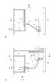
本発明は、転炉の耐火物プロフィールを測定するためのプロフィールメーター8を配置するに際し、炉裏側32の建屋構築物22に固定された架台2と、架台2に接続された移動装置3であって、プロフィールメーター8を前進位置33と後退位置34との間で移動させる移動装置3とを有することを特徴とする。架台2を固定するための建屋構築物22としては、炉裏側32の炉床21からみて天井位置となる部位の鉄骨構造部分を用いることができる。架台2とプロフィールメーター8との間に配置する移動装置3は、例えば架台2側に設けたレール4上を移動台車5が直線的に前進後退する機構を採用することができる。移動台車5にアーム7を設け、アーム7の先端にプロフィールメーター8を配置することができる。移動台車5をレール4上で前進後退させることにより、プロフィールメーター8を前進位置33と後退位置34のそれぞれに配置することができる。図1では、前進位置33を実線、後退位置34を2点鎖線で示している。このように、建屋構築物22に固定した架台2を用い、架台2とプロフィールメーター8との間を移動装置3で接続しているので、前進位置33、後退位置34ともに、プロフィールメーター8を常に同一位置に精度良く停止することができる。
The present invention comprises a
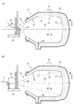
図1、図2(A)によって、プロフィールメーター8の配置位置である前進位置33について説明する。通常の転炉断面における耐火物炉内側表面形状は、炉底部13、円筒状の炉腹部14、炉口12に向かって幅すぼまりとなる炉上部15から形成される。炉口12の外側からプロフィールメーター8によって炉内部を観察するに際し、プロフィールメーター8から炉口12までの距離が遠すぎると、炉上部15の耐火物炉内側表面17が炉口12に隠れて観察することができない。さらに炉口12からの距離が遠ざかると、炉腹部14の耐火物炉内側表面17も炉口12に隠れて見えなくなる。従って、プロフィールメーター8の前進位置33において、炉上部15の耐火物炉内側表面17まで観察しようとすると、できるかぎりプロフィールメーター8を炉口12に近づけた位置にする必要がある。
The forward position 33, which is the arrangement position of the
転炉11を炉裏側に90°傾転したとき(θ=90°)(以下「90°傾転位置38」と呼ぶ。)、炉床21と平行に水平に伸びる炉軸18の方向にプロフィールメーター8が配置されるように、前進位置33を定めると好ましい。さらに上述のように、前進位置33においてはプロフィールメーター8をできるかぎり炉口12に近づけると好ましい。炉裏側32の炉床上部空間と転炉との間には、防護壁23が設けられている。転炉炉口12を炉裏側32に傾転したときの炉内からの輻射熱を防護壁23によって防ぐことができる。防護壁23は通常窓24を設け、窓24は開閉可能に設けられる。プロフィールメーター8の前進位置33においては、防護壁23の窓24を開の位置とするとともに、プロフィールメーター8が防護壁23配置位置まで転炉の炉口12に近づいた位置とすると好ましい。これにより、転炉11の炉上部15の耐火物炉内側表面17までプロフィールメーター8の撮像範囲43とし、観察することが可能となる(図2(A))。図2(A)では上下方向40の撮像範囲43を示しているが、左右方向(傾動軸方向42)についても同様の撮像範囲43を有している。防護壁23配置位置よりもさらに炉口12に近い位置まで前進すると、転炉上部空間からの落下物の通過位置となるので好ましくない。
When the
以上のように、プロフィールメーター8の前進位置33は、転炉の炉口12を炉裏側32に傾転したときにプロフィールメーター8によって炉口12を通して転炉炉内の耐火物炉内側表面17形状の一部又は全部を観察可能な位置とする。
As described above, the forward position 33 of the
また上述のように、プロフィールメーター8の前進位置33は、炉口12にできるだけ近づける必要から、炉裏側32の防護壁23の窓24を開いた状態で配置可能な位置となることから、防護壁23の窓24を閉じるためには、プロフィールメーター8が後退して転炉11から遠ざかる位置に待避する必要がある。本発明では、移動装置3によってプロフィールメーター8を移動可能であり、前進位置33は後退位置34よりもプロフィールメーター8と炉口12との距離が近接する位置とする。これにより、プロフィールメーター8を後退位置34に配置すれば(図1の2点鎖線部参照)、防護壁23の窓24を閉とすることができる。
Further, as described above, the forward position 33 of the
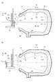
本発明において好ましくは、プロフィールメーター8の後退位置34においても転炉炉内の耐火物プロフィールを測定可能とする(図2(B))。炉裏側32の防護壁23に設けた窓24を開くことにより、後退位置34からでも炉内の一部を観察可能とすることができる。防護壁23の窓24を開としたとき、プロフィールメーター8を後退位置34に配置し、かつ転炉を90°傾転位置38とし、窓24を通じてプロフィールメーター8の撮像範囲43として少なくとも転炉11の炉底部13が観察可能となるように窓24を設けると好ましい。これにより、防護壁23の窓24を通じて転炉炉壁一部の耐火物プロフィールが測定可能となる。例えば、転炉出鋼中、転炉傾動角度θが90°となったタイミングをとらえ、防護壁23の窓24を開き、後退位置34に配置したプロフィールメーター8で炉内を観察することにより、炉底部13の耐火物プロフィールを測定することができる。このような測定が可能になるので、転炉のサイクルタイムに一切影響を及ぼすことなく、少なくとも転炉の炉底部13について、1ヒートに1回の耐火物プロフィール測定が可能となる。
In the present invention, preferably, the refractory profile in the converter can be measured even at the retracted
プロフィールメーター8の前進位置33、後退位置34の両方で耐火物プロフィール測定を行うためには、前進位置33、後退位置34ともに、90°傾転位置38における炉軸18上にプロフィールメーター8を設けると好ましい。このとき、前進位置33と後退位置34との間の移動経路は、90°傾転位置38における炉軸18と一致することとなる。
In order to measure the refractory profile at both the forward position 33 and the
本発明は、プロフィールメーター8を建屋構築物22に接続する構造としているので、プロフィールメーター8の前進位置33、後退位置34における位置再現性は、前後左右上下いずれも±1mm以内とすることができる。また、任意の傾動角度で転炉を停止したときの、実際の傾動角度と計測した傾動角度との間の誤差についても、±0.1°以内とすることができる。これにより、転炉の耐火物炉内側表面形状(耐火物プロフィール)における耐火物厚み方向での測定精度を、炉底部13で±7mm、炉腹部14で±7mm、炉上部15で±10mmに維持することが可能となる。
Since the present invention has a structure in which the
本発明は以上のように、耐火物プロフィール測定時における転炉11とプロフィールメーター8との位置関係を、角度を含めて再現性良く配置することができるので、特許文献1に記載の方法と相違し、転炉炉口近傍に設けた3つの基準点を用いる必要がない。一方、前進位置33、後退位置34におけるプロフィールメーター8の配置位置が予定位置であることを確認する意味において、撮像範囲内のいずれかの固定点を基準点として用いることは好ましい。
As described above, the present invention is different from the method described in
本発明で用いるプロフィールメーター8については、2次元の撮像範囲43の各撮像部位において撮像対象までの距離を計測することのできる形状測定装置であればいずれの形式であっても良い。例えば、ステレオ写真方式、即ち、撮影方向に垂直な方向に所定の距離で離れた2つの撮影系を設け、同一対象に対して撮影角度を異にした複数の画像を撮像するものを用いることができる。また、レーザー、マイクロ波、超音波等を利用する各種距離計であって、2次元の撮像範囲の各撮像部位までの距離を計測できる距離計を用いることもできる。レーザー式距離計であれば、光源からレーザービームを撮影対象に照射し、撮像範囲内においてレーザービームの照射方向をスキャンすることにより、2次元の範囲を計測することができる。レーザービームの反射光を受光器で受光し、レーザーの照射から反射光の受光までに要する時間を計測して距離を測定する。ここで2次元の撮像範囲43とは、上下方向40と左右方向(傾動軸方向42)の両方向に撮像範囲を有していることを意味する。
The
転炉炉裏側32の炉床21の上部空間は、種々の作業を行う空間でもある。転炉出鋼終了時のスラグ流出を低減するため、スラグダーツ25を用いることがある(図5参照)。スラグダーツ25を炉内に投入するに際しては、スラグダーツ投入装置26が炉裏側32の炉床上部空間に配置される。本発明の耐火物プロフィール測定装置1は、測定を行わない待機時期においては、炉床上の諸作業を妨害しないように収納されていると好ましい。例えば、移動装置3とプロフィールメーター8とを接続するアーム7について、移動装置3付近の回動軸6を中心に回動可能に設け、待機時期においては、図3の実線で示すように、アーム7とプロフィールメーター8の両方が移動装置付近の待機位置37に収納される。そして耐火物プロフィール測定時には、図3の2点鎖線部で示すように、アーム7を回動して測定位置35とする。図3では後退位置34に配置されている。さらに図4で示すように、後退位置34(実線)から、前進位置33(2点鎖線)にプロフィールメーター8を移動することができる。
The upper space of the
上記本発明の転炉耐火物プロフィール測定装置を用いた転炉耐火物プロフィール測定方法においては、異なった2つのタイミングにおいて、転炉炉口12を炉裏側32に傾転し、前進位置33と後退位置34の一方又は両方においてプロフィールメーター8を用いて転炉の耐火物プロフィールを計測し、2つのタイミングの耐火物プロフィールを対比することによって2つのタイミング間での各部位の耐火物の厚み増減量を評価することができる。上記異なった2つのタイミングとしては、例えば第1のタイミングを、転炉耐火物のウェア煉瓦を築造した直後のタイミングとし、第2のタイミングを、転炉稼働中の任意のタイミングとする。炉裏側32の転炉傾動角度としては、90°傾転位置38を用いることができる。第1のタイミングと第2のタイミングにおける耐火物プロフィールの測定結果を対比することにより、ウェア煉瓦築造直後と対比して、第2のタイミング時における各部位の耐火物厚み増減量を評価することができる。図2に示す耐火物16の炉内側表面17は、転炉耐火物のウェア煉瓦を築造した直後の状況を示す。図6においては、第1のタイミングにおける転炉耐火物のウェア煉瓦を築造した直後の耐火物の炉内側表面17aを2点鎖線、第2のタイミングにおける転炉稼働中の耐火物の炉内側表面17を実線で示している。なお、ウェア煉瓦築造時の耐火物プロフィールについては、プロフィールメーター8を用いた測定に替えて、煉瓦築造図面から読み取った耐火物プロフィールを用いることとしても良い。
In the converter refractory profile measuring method using the converter refractory profile measuring device of the present invention, the converter
本発明において、プロフィールメーター8によって耐火物プロフィールを測定するに際し、転炉傾動角度θを90°とすると好ましいが、90°以外の角度であっても良い。θ=90°±15°の範囲であれば、測定を行うことができる。また、異なった2つのタイミングで計測するに際し、両者が同じ転炉傾動角度であると好ましいが、異なった転炉傾動角度θであってもかまわない。ただし、いずれの転炉傾動角度であっても、転炉傾動角度θの実績値を±0.1°の精度で正確に計測できることが必要である。
In the present invention, when measuring the refractory profile with the
前進位置33におけるプロフィールメーター8の配置位置は、傾転した転炉11の炉軸18と交わる位置であることが好ましいが、炉軸18から離れていても計測は可能である。炉軸からの距離が±300mmの範囲であれば十分に計測することができる。また、異なった2つのタイミングで計測するに際し、プロフィールメーター8の位置が同一であると好ましいが、異なった位置に配置してもかまわない。ただし、いずれの位置についても、プロフィールメーター8の位置が±1mmの精度で正確に計測できることが必要である。
The position of the
前進位置におけるプロフィールメーターの撮像中心方向については、炉軸18に平行であることが好ましいが、平行から外れていても良い。また、異なった2つのタイミングで計測するに際し、プロフィールメーターの撮像中心方向が異なっていても良い。
The image pickup center direction of the profile meter at the forward position is preferably parallel to the
後退位置34においても耐火物プロフィールを計測する場合、転炉傾動角度θ、プロフィールメーター8の配置位置、プロフィールメーター8の撮像中心方向に関して、上記前進位置33と同様の配慮が必要となる。
When measuring the refractory profile also in the retracted
300トン上底吹き転炉において、本発明を適用した。当該転炉11は、炉裏側32への90°傾転位置38において、炉軸18が炉床21の上方1300mmの位置となる。炉裏側32の炉床上の空間と転炉11との間には、防護壁23が設けられている。また防護壁23には、開閉可能な窓24が設けられている(図1参照)。
The present invention was applied in a 300-ton top-bottom blown converter. In the
炉裏側32の炉床21からみて天井位置となる部位の鉄骨構造部分(建屋構築物22)に、本発明の架台2を固定した。また、架台2に移動装置3を設けた。移動装置3は、架台2側に設けたレール4上を移動台車5が直線的に前進後退する機構を採用している。移動台車5には、回動軸6を経由してアーム7を設け、アーム7の先端にプロフィールメーター8を配置している。アーム7は、電動シリンダーによって回動軸6まわりに回動できる。アーム7を回動軸6まわりに回動することにより、アーム7を測定位置35と待機位置37の間で移動することができる(図3、図5参照)。測定位置35と待機位置37の間に、準備位置36を有している(図5参照)。アーム7が測定位置35にあるとき、移動装置3の移動により、プロフィールメーター8を前進位置33と後退位置34に配置することができる(図4参照)。前進位置33、後退位置34ともに、プロフィールメーター8は、90°傾転位置38における炉軸18に沿った位置に配置される。90°傾転位置38における転炉の炉口12先端部とプロフィールメーター8との間の距離は、前進位置33において1400mm、後退位置34において4200mmとなる。
The
プロフィールメーター8として、レーザー距離計方式の市販のものを用いた。撮像範囲は、上下方向40、左右方向(傾動軸方向42)ともに110°の範囲である。前進位置33において、炉口12を通して炉内の耐火物表面の全体を観察することができる。一方、後退位置34において、防護壁23に設けた窓24を通して上下方向・左右方向ともに25°の範囲を観察可能であり、炉底部13の全体を観察することができる。
As the
プロフィールメーター8の停止位置精度は、前後左右上下いずれも±1mm以内であり、転炉傾動時の実際の傾動角度と計測した角度との誤差は±0.1°以内である。そのため、何ら基準点を設けることなく、炉内の耐火物プロフィールを、耐火物の厚み方向に、炉底部13で±7mm、炉腹部14で±7mm、炉上部15で±10mmの精度で測定することができる。
The accuracy of the stop position of the
図5に示すように、アーム7を待機位置37(2点鎖線)とすると、炉裏側32の炉床21上で行われる通常の作業を支障なく行うことができる。準備位置36(実線)においては、出鋼中の作業であるスラグダーツ25を炉内溶鋼表面に投入する作業を行うことができる。測定位置35(2点鎖線)では、スラグダーツ投入作業を行うことができない。本実施例では、アーム7を準備位置36に配置し、転炉出鋼中においてアーム7を準備位置36から測定位置35(後退位置34)に移動し、90°傾転位置38のタイミングでプロフィールメーター8によって炉底部13の撮像を行い(図2(B))、直ちにアーム7を測定位置35から準備位置36に戻すまでの全作業を60秒以内に完了することができる。そのため、90°傾転位置38でプロフィールの測定を行って準備位置まで戻った後に、出鋼終了時のスラグダーツ投入作業を何ら遅滞なく行うことができる。以上のとおりであるから、プロフィールメーター8を後退位置34に配置して転炉炉底部13のプロフィールを計測するに際しては、転炉出鋼作業中に作業を行い、転炉のサイクルタイムに何ら影響を及ぼすことなく測定を完了することができる。
As shown in FIG. 5, when the
転炉の出鋼と排滓が終了し、次ヒートの原料装入までに若干の時間を割くことが可能であるタイミングをとらえ、プロフィールメーター8を前進位置33に配置した測定を行う。排滓完了後に転炉11を炉裏側の90°傾転位置38に傾動し、炉裏側32の防護壁23の窓24を開とし、プロフィールメーター8を前進位置33に配置する(図2(A))。この状態で撮像を行うことにより、炉内の耐火物表面の全体を撮像範囲43とし、耐火物プロフィールを計測することが可能である。出鋼と排滓を終了しているので、耐火物表面が溶鋼やスラグで覆われておらず、すべての表面が露出しており、撮像が可能である。このような測定を行う場合でも、転炉のサイクルタイムに及ぼす影響はせいぜい2分以内に抑えることができる。
The
まず、転炉のウェア煉瓦を築造した直後の耐火物プロフィールを、本発明装置によって測定し(図2(A))、初期プロフィールとして記録する。次に、転炉のヒート毎の出鋼時に、プロフィールメーター8を後退位置34に配置した上で炉底部13の耐火物プロフィールを測定する(図6(B))。初期プロフィールとの耐火物厚み差を算出し、耐火物損耗量として2次元マップ上に表示した。さらに、10ヒートに1回の割合で、防護壁23の窓24を開き、プロフィールメーター8を前進位置33に配置した上で炉内の全表面について耐火物プロフィールを測定し(図6(A))、同じく初期プロフィールとの耐火物厚み差を算出し、耐火物損耗量として2次元マップ上に表示した。
First, the refractory profile immediately after the ware brick of the converter is constructed is measured by the apparatus of the present invention (FIG. 2 (A)) and recorded as an initial profile. Next, at the time of steel removal for each heat of the converter, the
表示されたマップ上において、耐火物損耗量が部分的に進行している部位が見出された場合には、当該進行している部位について集中的に、補修用の耐火物を吹き付けることによって補修を行い、損耗の進行を抑えることができた。損耗が進行していない部位への無駄な耐火物吹き付けを防止できるので、補修用耐火物の使用原単位を削減した上で、必要な耐火物寿命を確保することができた。 If a part of the refractory wear is found on the displayed map, it is repaired by spraying the refractory for repair intensively on the part where the amount of wear is progressing. Was able to suppress the progress of wear. Since it is possible to prevent unnecessary spraying of the refractory on the part where the wear has not progressed, it was possible to secure the required life of the refractory while reducing the basic unit of the refractory for repair.
1 転炉耐火物プロフィール測定装置
2 架台
3 移動装置
4 レール
5 移動台車
6 回動軸
7 アーム
8 プロフィールメーター
11 転炉
12 炉口
13 炉底部
14 炉腹部
15 炉上部
16 耐火物
17 炉内側表面
18 炉軸
19 傾動軸
20 出鋼口
21 炉床
22 建屋構築物
23 防護壁
24 窓
25 スラグダーツ
26 スラグダーツ投入装置
31 炉前側
32 炉裏側
33 前進位置
34 後退位置
35 測定位置
36 準備位置
37 待機位置
38 90°傾転位置
39 炉体原点
40 高さ方向
41 前後方向
42 傾動軸方向
43 撮像範囲
θ 転炉傾動角度
1 converter refractory
Claims (3)
転炉からの出鋼時に転炉炉口が傾転する側(以下「炉裏側」という。)の炉床よりも上方の建屋構築物に固定された架台と、2次元の撮像範囲の各撮像部位において撮像対象までの距離を計測することのできる形状測定装置(以下「プロフィールメーター」という。)と、前記架台に接続された移動装置であって、移動台車をレールに沿って前進後退させることによって前記プロフィールメーターを前進位置と後退位置との間で移動させる移動装置とを有し、
前記前進位置は、転炉の炉口を炉裏側に傾転したときに前記プロフィールメーターによって炉口を通して転炉炉内の耐火物炉内側表面形状の一部又は全部を観察可能な位置であって、前進位置は後退位置よりもプロフィールメーターと炉口との距離が近接する位置であることを特徴とする転炉耐火物プロフィール測定装置。 Refractory of converter A device that measures the inner surface shape of a furnace (hereinafter referred to as "refractory profile").
A gantry fixed to the building structure above the hearth on the side where the converter opening is tilted when steel is ejected from the converter (hereinafter referred to as the "backside"), and each imaging part in the two-dimensional imaging range. A shape measuring device (hereinafter referred to as "profile meter") capable of measuring the distance to the imaging target, and a moving device connected to the gantry, by moving the moving trolley forward and backward along the rail. It has a moving device for moving the profile meter between a forward position and a backward position.
The forward position is a position where a part or all of the surface shape of the refractory inside the converter can be observed through the furnace opening by the profile meter when the furnace opening of the converter is tilted toward the back of the furnace. A converter refractory profile measuring device characterized in that the forward position is a position where the distance between the profile meter and the furnace opening is closer than the backward position.
異なった2つのタイミングにおいて、転炉炉口を炉裏側に傾転し、前記前進位置と後退位置の一方又は両方において前記プロフィールメーターを用いて転炉の耐火物プロフィールを計測し、2つのタイミングの耐火物プロフィールを対比することによって2つのタイミング間での耐火物の厚み増減量を評価することを特徴とする転炉耐火物プロフィール測定方法。 A method for measuring a converter refractory profile using the converter refractory profile measuring device according to claim 1 or 2.
At two different timings, the converter opening is tilted toward the back of the furnace, and the refractory profile of the converter is measured using the profile meter at one or both of the forward position and the backward position, and the refractory profile of the converter is measured at two timings. A method for measuring a converter refractory profile, which comprises evaluating the amount of increase / decrease in the thickness of the refractory between two timings by comparing the refractory profiles.
Priority Applications (1)
| Application Number | Priority Date | Filing Date | Title |
|---|---|---|---|
| JP2017088035A JP6848652B2 (en) | 2017-04-27 | 2017-04-27 | Converter refractory profile measuring device and converter refractory profile measuring method |
Applications Claiming Priority (1)
| Application Number | Priority Date | Filing Date | Title |
|---|---|---|---|
| JP2017088035A JP6848652B2 (en) | 2017-04-27 | 2017-04-27 | Converter refractory profile measuring device and converter refractory profile measuring method |
Publications (2)
| Publication Number | Publication Date |
|---|---|
| JP2018185253A JP2018185253A (en) | 2018-11-22 |
| JP6848652B2 true JP6848652B2 (en) | 2021-03-24 |
Family
ID=64356561
Family Applications (1)
| Application Number | Title | Priority Date | Filing Date |
|---|---|---|---|
| JP2017088035A Active JP6848652B2 (en) | 2017-04-27 | 2017-04-27 | Converter refractory profile measuring device and converter refractory profile measuring method |
Country Status (1)
| Country | Link |
|---|---|
| JP (1) | JP6848652B2 (en) |
Families Citing this family (5)
| Publication number | Priority date | Publication date | Assignee | Title |
|---|---|---|---|---|
| WO2020107123A1 (en) * | 2018-11-29 | 2020-06-04 | Ha Hieu Thuan Charles | Projection device for displaying construction plans |
| PL3987247T3 (en) * | 2019-06-18 | 2024-06-17 | Process Metrix, Llc | System, device and method for measuring the interior refractory lining of a vessel |
| JP7277744B2 (en) * | 2019-07-09 | 2023-05-19 | 日本製鉄株式会社 | Hot Diagnosis Method for Refractories |
| CN111239185A (en) * | 2020-03-31 | 2020-06-05 | 广州市建筑材料工业研究所有限公司 | Device and method for testing fire resistance of sample with adjustable inclination angle |
| JP7516888B2 (en) | 2020-06-11 | 2024-07-17 | トヨタ自動車株式会社 | Refractory wear evaluation device |
Family Cites Families (6)
| Publication number | Priority date | Publication date | Assignee | Title |
|---|---|---|---|---|
| JPS6186607A (en) * | 1984-10-04 | 1986-05-02 | Sumitomo Metal Ind Ltd | Apparatus for measuring melted shape of refractory material of container lined by refractory material |
| US4893933A (en) * | 1987-09-30 | 1990-01-16 | Armco Inc. | Automatic BOF vessel remaining lining profiler and method |
| FI94906C (en) * | 1993-05-21 | 1995-11-10 | Rautaruukki Oy | Procedure for measuring the wear of the casing in a swivel shaft and orifice |
| US6922252B2 (en) * | 2002-09-19 | 2005-07-26 | Process Matrix, Llc | Automated positioning method for contouring measurements using a mobile range measurement system |
| JP2009068982A (en) * | 2007-09-13 | 2009-04-02 | Jfe Steel Kk | Profile measurement method of refractory material in converter, and thickness measurement method of refractory material |
| JP6289226B2 (en) * | 2014-04-08 | 2018-03-07 | 大同特殊鋼株式会社 | Temperature furnace sampling equipment for arc furnace |
-
2017
- 2017-04-27 JP JP2017088035A patent/JP6848652B2/en active Active
Also Published As
| Publication number | Publication date |
|---|---|
| JP2018185253A (en) | 2018-11-22 |
Similar Documents
| Publication | Publication Date | Title |
|---|---|---|
| JP6848652B2 (en) | Converter refractory profile measuring device and converter refractory profile measuring method | |
| JP6683727B2 (en) | Evaluation of fireproof lining of metal container using autonomous scanner | |
| US4893933A (en) | Automatic BOF vessel remaining lining profiler and method | |
| US8072613B2 (en) | System for measuring the inner space of a container and method of performing the same | |
| US8083982B2 (en) | Method for repairing a protective lining of an industrial reaction or transport vessel | |
| JP4383313B2 (en) | Method and apparatus for measuring surface shape of blast furnace interior | |
| US10837704B2 (en) | Method for repairing a refractory lining of a metallurgical vessel in the hot state | |
| JP2022538021A (en) | Systems, devices and methods for measuring internal refractory linings of vessels | |
| JP2009068982A (en) | Profile measurement method of refractory material in converter, and thickness measurement method of refractory material | |
| KR20190103247A (en) | Diagnostic support device, diagnostic support method, diagnostic method and repair method of vacuum degassing tank | |
| JP2009002765A (en) | Profile measuring method of refractory, and thickness measuring method of refractory | |
| JPH0920906A (en) | Method for measuring profile of furnace wall of blast furnace and its instrument | |
| JPS6186607A (en) | Apparatus for measuring melted shape of refractory material of container lined by refractory material | |
| JPH0384393A (en) | Measuring device for thickness of side walls for ladle | |
| JP2014032115A (en) | Shape measuring device and measuring method of refractory body | |
| CN110174053B (en) | Method for measuring size of hearth when opening degree of converter mouth is smaller than radius of hearth | |
| RU221616U1 (en) | Manipulator for gunning of industrial equipment | |
| Banerjee et al. | Laser contouring of steelmaking vessels | |
| JP2024125404A (en) | Method for measuring refractory surface shape and method for measuring refractory wear amount | |
| EP2827088A1 (en) | Tap hole measuring device for a bof vessel and method for measuring the thickness of a refractory lining in a tap hole of a bof vessel | |
| JPS62288685A (en) | Method for repairing furnace wall of coke oven | |
| CN110527779A (en) | It is a kind of for measuring the measuring device of converter mouth size | |
| EA036217B1 (en) | Automated refractory lining method and robotic center for implementing the same | |
| ES1301002U (en) | INSTALLATION, ROBOT AND HEAD TO SPRAY A PRODUCT INSIDE A SUITABLE CONTAINER TO CONTAIN MOLTEN METAL (Machine-translation by Google Translate, not legally binding) | |
| JPH045515A (en) | Measuring method for internal wall of furnace |
Legal Events
| Date | Code | Title | Description |
|---|---|---|---|
| A621 | Written request for application examination |
Free format text: JAPANESE INTERMEDIATE CODE: A621 Effective date: 20191204 |
|
| A977 | Report on retrieval |
Free format text: JAPANESE INTERMEDIATE CODE: A971007 Effective date: 20201027 |
|
| A131 | Notification of reasons for refusal |
Free format text: JAPANESE INTERMEDIATE CODE: A131 Effective date: 20201110 |
|
| A521 | Written amendment |
Free format text: JAPANESE INTERMEDIATE CODE: A523 Effective date: 20201127 |
|
| TRDD | Decision of grant or rejection written | ||
| A01 | Written decision to grant a patent or to grant a registration (utility model) |
Free format text: JAPANESE INTERMEDIATE CODE: A01 Effective date: 20210202 |
|
| A61 | First payment of annual fees (during grant procedure) |
Free format text: JAPANESE INTERMEDIATE CODE: A61 Effective date: 20210215 |
|
| R151 | Written notification of patent or utility model registration |
Ref document number: 6848652 Country of ref document: JP Free format text: JAPANESE INTERMEDIATE CODE: R151 |