EP1507985B1 - Verbesserter gewindeeinsatz für befestiger - Google Patents
Verbesserter gewindeeinsatz für befestiger Download PDFInfo
- Publication number
- EP1507985B1 EP1507985B1 EP03721924A EP03721924A EP1507985B1 EP 1507985 B1 EP1507985 B1 EP 1507985B1 EP 03721924 A EP03721924 A EP 03721924A EP 03721924 A EP03721924 A EP 03721924A EP 1507985 B1 EP1507985 B1 EP 1507985B1
- Authority
- EP
- European Patent Office
- Prior art keywords
- face
- key
- tang
- threaded insert
- bushing
- Prior art date
- Legal status (The legal status is an assumption and is not a legal conclusion. Google has not performed a legal analysis and makes no representation as to the accuracy of the status listed.)
- Expired - Lifetime
Links
Images


Classifications
-
- F—MECHANICAL ENGINEERING; LIGHTING; HEATING; WEAPONS; BLASTING
- F16—ENGINEERING ELEMENTS AND UNITS; GENERAL MEASURES FOR PRODUCING AND MAINTAINING EFFECTIVE FUNCTIONING OF MACHINES OR INSTALLATIONS; THERMAL INSULATION IN GENERAL
- F16B—DEVICES FOR FASTENING OR SECURING CONSTRUCTIONAL ELEMENTS OR MACHINE PARTS TOGETHER, e.g. NAILS, BOLTS, CIRCLIPS, CLAMPS, CLIPS OR WEDGES; JOINTS OR JOINTING
- F16B37/00—Nuts or like thread-engaging members
- F16B37/12—Nuts or like thread-engaging members with thread-engaging surfaces formed by inserted coil-springs, discs, or the like; Independent pieces of wound wire used as nuts; Threaded inserts for holes
- F16B37/122—Threaded inserts, e.g. "rampa bolts"
- F16B37/125—Threaded inserts, e.g. "rampa bolts" the external surface of the insert being threaded
-
- F—MECHANICAL ENGINEERING; LIGHTING; HEATING; WEAPONS; BLASTING
- F16—ENGINEERING ELEMENTS AND UNITS; GENERAL MEASURES FOR PRODUCING AND MAINTAINING EFFECTIVE FUNCTIONING OF MACHINES OR INSTALLATIONS; THERMAL INSULATION IN GENERAL
- F16B—DEVICES FOR FASTENING OR SECURING CONSTRUCTIONAL ELEMENTS OR MACHINE PARTS TOGETHER, e.g. NAILS, BOLTS, CIRCLIPS, CLAMPS, CLIPS OR WEDGES; JOINTS OR JOINTING
- F16B39/00—Locking of screws, bolts or nuts
- F16B39/02—Locking of screws, bolts or nuts in which the locking takes place after screwing down
- F16B39/04—Locking of screws, bolts or nuts in which the locking takes place after screwing down with a member penetrating the screw-threaded surface of at least one part, e.g. a pin, a wedge, cotter-pin, screw
- F16B39/06—Locking of screws, bolts or nuts in which the locking takes place after screwing down with a member penetrating the screw-threaded surface of at least one part, e.g. a pin, a wedge, cotter-pin, screw with a pin or staple parallel to the bolt axis
-
- Y—GENERAL TAGGING OF NEW TECHNOLOGICAL DEVELOPMENTS; GENERAL TAGGING OF CROSS-SECTIONAL TECHNOLOGIES SPANNING OVER SEVERAL SECTIONS OF THE IPC; TECHNICAL SUBJECTS COVERED BY FORMER USPC CROSS-REFERENCE ART COLLECTIONS [XRACs] AND DIGESTS
- Y10—TECHNICAL SUBJECTS COVERED BY FORMER USPC
- Y10S—TECHNICAL SUBJECTS COVERED BY FORMER USPC CROSS-REFERENCE ART COLLECTIONS [XRACs] AND DIGESTS
- Y10S411/00—Expanded, threaded, driven, headed, tool-deformed, or locked-threaded fastener
- Y10S411/924—Coupled nut and bolt
- Y10S411/929—Thread lock
- Y10S411/939—Longitudinal key
Definitions
- This invention relates generally to threaded inserts, and more particularly to a threaded insert having keys which are positioned within 90° straight wall slots
- Threaded inserts of the type to which this invention is directed are ordinarily used to provide strong, permanent threads in soft or ductile parent materials, especially when a mating stud or bolt is to be frequently removed. Threaded inserts are also used to repair stripped, damaged or worn threads in a parent material. Soft or ductile materials which have received threaded inserts typically exhibit improved load-carrying capacity under static and dynamic loading conditions.
- a prior art threaded insert includes a bushing portion having a cylindrical shape with a central bore throughout the length of the threaded insert.
- the bushing portion also includes female threads throughout the length of the surface within the central bore and male threads throughout the length of the external surface of the bushing portion.
- the male threads on the external surface of the bushing portion are configured to mate with a threaded hole within a parent material, such as a plate or casting made of aluminum or magnesium.
- the female threads within the central bore are configured to mate with a male threaded fastener, such as a bolt or stud.
- the threaded insert is typically made from a material which is stronger than the parent material, such as steel.
- the threaded insert includes at least one key.
- the at least one key is ordinarily positioned within a dovetail slot which extends longitudinally along the external surface of the threaded insert.
- the depth of the dovetail slot is typically greater than the depth of the male threads on the external surface of the threaded insert.
- the dovetail slot is added to the threaded insert through a broaching operation.
- the broaching operation includes forcing an elongated, serrated cutting tool having sequentially larger teeth in the form of the dovetail slot along the external surface of the threaded insert.
- the broaching step generally requires an additional machine set-up, which can lead to increased manufacturing costs.
- broaching tools are often relatively expensive compared to other types of tools, thus adding further to the manufacturing costs of the threaded insert.
- the dovetail slot is deburred to remove any protruding ragged edges that may have been raised on the male threads on the external surface of the threaded insert during the broaching operation.
- the deburring operation is often performed by hand, which can add to the time and cost required to fabricate the threaded insert.
- the key includes a tang portion and a locking portion with the tang portion and the locking portion being positioned adjacent each other and aligned longitudinally.
- a cross-section of the tang portion includes a substantially rectangular shape, while a cross-section of the locking portion includes a substantially triangular shape.
- the tang portion is positioned within the dovetail slot through an interference fit.
- An inside surface on the tang portion is preferably in contact with the bottom surface of the dovetail slot and the outside facing edges of the tang portion are broached into the angled surfaces of the dovetail slot.
- the thickness of the tang portion is sufficiently low that with the tang portion being in contact with the bottom surface of the dovetail slot, the outer corners of the tang portion remain deeper than the inside diameter of the male threads on the external surface of the threaded insert. This prevents the tang portion from interfering with the threads within the hole in the parent material during installation of the threaded insert.
- the locking portion Prior to installation of the threaded insert into the parent material, the locking portion is positioned beyond the end of the bushing portion of the threaded insert. The thickness of the locking portion is sufficient that the outermost portion of the locking portion is positioned substantially flush with the outside diameter of the male threads on the external surface of the threaded insert.
- the inside surface of the tang portion of the key is substantially aligned with the bottom surface of the dovetail slot at an end of the threaded insert.
- a longitudinal force is applied to the key so that the tang portion of the key is pushed into the dovetail slot with the outside edges of the tang portion being broached into the angled surfaces of the dovetail slot.
- the inside surface of the tang portion may inadvertently be installed offset from the bottom surface of the dovetail slot.
- a key resetting operation is performed to ensure that the tang portion is not positioned within the male threads on the external surface of the threaded insert.
- the key resetting operation includes applying a force to the tang portion of the key in a direction substantially perpendicular to the bottom surface of the dovetail slot.
- the key resetting operation may cause the key to be pushed out of the newly broached portion of the angled surfaces of the slot and to become loose, which may be a sufficient reason to scrap the threaded insert.
- the key resetting operation is a process which increases the manufacturing cost of the threaded insert.
- the threaded insert may be screwed into the threaded hole in the parent material until the locking portion of the at least one key on the threaded insert contacts a surface of the parent material.
- the at least one key is then driven into the parent material so that the locking portion of the key broaches through the threads of the threaded hole in the parent material and remains in place within the threads in the parent material. Having the key in place within the threads in the parent material locks the threaded insert in place by preventing further rotation of the threaded insert within the threaded hole in the parent material.
- the tang portion of the key is simultaneously broached further into the angled surface of the dovetail slot, thereby adding to the difficulty of driving the key into the parent material.
- GB-A-1,246,657 discloses an example of a locking screw fastener with a plurality of locking pins.
- the fastener comprising an insert fastener with an internally threaded bore and an external screw thread on its outer surface, there being grooves extending longitudinally through the external screw thread.
- the grooves receive locking pins with a longitudinally extending guide portion and a prism shaped cutting portion.
- the cutting portion further comprises a cutting edge lying in a plane normal to the longitudinal axis of the locking pin.
- the locking screw fastener is used substantially as previously described.
- the present invention is directed to a threaded insert having keys which are positioned within slots having substantially parallel walls that are substantially perpendicular to the bottom surface of the slot.
- the threaded insert includes at least one key. While those skilled in the art will recognize that more than one key and slot may be provided within the scope of the invention, reference will be made to an embodiment wherein only one key, slot and related surfaces are described.
- the key includes a substantially longitudinal tang portion having a first end, a second end, a first face, a second face, a first side surface and a second side surface.
- the first face and the second face are substantially parallel and have a curved profile, the first face having a concave surface and the second face having a convex surface.
- the first and second side surfaces are adjacent to the first face and the second face.
- the key also includes a substantially longitudinal locking portion having a first end, a second end and a substantially triangular cross-section which forms a back face and two angled faces.
- the second end of the locking portion is positioned adjacent the first end of the tang portion such that the tang portion and the locking portion are substantially longitudinally aligned.
- the back face is substantially longitudinally aligned with an apex of the first face of the tang portion, while the intersection of the two angled faces project beyond an apex of the second surface of the tang portion.
- the threaded insert also includes a bushing portion.
- the bushing portion includes a substantially cylindrical shape with a first end, a second end and a central bore therethrough.
- a surface of the central bore includes female threads throughout the length of the bushing portion, while an external surface of the bushing portion includes male threads throughout the length of the bushing portion.
- the bushing portion also includes at least one slot which is positioned on the external surface and extends substantially longitudinally throughout the length of the bushing portion.
- the slot includes a bottom surface and two wall surfaces. The two wall surfaces are substantially parallel to each other and substantially perpendicular to the bottom surface with the depth of the slot being greater than the depth of the male threads on the external surface.
- the tang portion of the key is positioned within the slot toward the first end of the bushing portion.
- the edges between the first face and the first and second side surfaces of the tang portion are positioned in contact with the bottom surface of the slot in the bushing portion.
- the edges between the second face and the first and second side surfaces of the tang portion have an interference fit with the two walls within the slot of the bushing portion.
- the locking portion of the key extends beyond the first end of the bushing portion.
- the depth of the slot of the bushing portion is sufficient that the apex of the second surface of the tang portion of the prior art key is positioned at a depth which is deeper than the inside diameter of the male threads on the external surface of the bushing portion.
- the depth of the slot of the bushing portion also places the intersection of the two angled faces of the locking portion of the corresponding key at a depth which is shallower than the inside diameter of the male threads on the external surface of the bushing portion.
- the male threads on the external surface of the bushing portion are configured to mate with a threaded hole in a parent material, while the female threads within the central bore are configured to mate with a male threaded fastener.
- the key includes four keys which are positioned approximately ninety degrees apart from each other about the circumference of the bushing portion.
- the first and second side surfaces of the tang portion of the key are substantially perpendicular to tangents along the first face of the tang portion at the intersection of the first face and the first and second sides respectively.
- the angled faces of the locking portion of the key taper into the second face of the tang portion of the key.
- the taper includes an angled taper, while in another currently preferred embodiment of the invention the taper includes a curved taper.
- the intersection of the angled faces of the locking portion of the key may be positioned either above flush, below flush or substantially flush with the outside diameter of the male threads on the external surface of the bushing portion.
- the locking portion of the key further includes an end surface at the first end of the locking portion. The end surface is substantially perpendicular to the back face and the two angled faces of the locking portion.
- the entire locking portion of the key extends beyond the first end of the bushing portion.
- the first side surface and the second side surface of the tang portion of the key have an interference fit with the two walls within the slot of the bushing portion.
- the invention also includes a currently preferred method of assembling the threaded insert.
- the method includes providing the key and the bushing portion.
- the method also includes positioning the tang portion of the key within the slot toward the first end of the bushing portion such that the edges between the first face of the tang portion and the first and second side surfaces of the tang portion are in contact with the bottom surface of the slot in the bushing portion.
- the tang portion is also positioned such that the locking portion of the key extends beyond the first end of the bushing portion.
- the method further includes applying a force to the second face of the tang portion of the key in a direction substantially perpendicular to the bottom surface of the slot.
- the force is applied until the curved profile of the tang portion of the key is reduced and an apex of the second face of the tang portion is positioned at a depth which is deeper than the inside diameter of the external threads of the bushing portion.
- the force is also applied until an interference fit is formed between the tang portion of the key and the slot of the bushing portion.
- applying a force to the second face of the tang portion includes applying the force until the interference fit is formed between the walls of the slot of the bushing portion and the edges between the second face and the first and second sides of the tang portion of the key.
- applying a force to the second face of the tang portion includes applying the force until the interference fit is formed between the walls of the slot of the bushing portion and the first and second side surfaces of the tang portion of the key.
- the invention provides for a threaded insert having at least one key which is positioned within a slot having parallel walls that are perpendicular to the bottom surface of the slot. It may also be seen that the key has less tendency to broach into the slot within the bushing portion and that the threaded insert is configured for improved key driving compared to prior art threaded inserts. Additionally, it may be seen that the threaded insert of the invention can be manufactured more economically and with improved retention and alignment of the key compared to prior art threaded inserts.
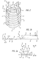
- FIG. 2 depicts a threaded insert 20 of the present invention.
- the threaded insert 20 includes a bushing portion 22 having a substantially cylindrical shape with a first end 24, a second end 26 and a central bore 28 therethrough.
- a surface of the central bore 28 includes female threads 30 throughout the length of the bushing portion 22, while an external surface 32 of the bushing portion includes male threads 34 throughout the length of the bushing portion.
- the male threads 34 may be configured to mate with a threaded hole 36 (FIGS. 5a and 5b) in a parent material 38, such as a plate or casting, while the female threads 30 may be configured to mate with a male threaded fastener, such as a bolt or a stud (not shown).
- the threaded insert 20 also includes at least one key 40 for ensuring that the threaded insert does not rotate within the threaded hole in the parent material after installation into the parent material.
- Each of the keys 40 is positioned within a slot 42 which extends substantially longitudinally along the external surface 32 of the bushing portion 22.
- the threaded insert 20 includes four keys 40 which are positioned within four respective slots arranged approximately ninety degrees apart from each other about the circumference of the bushing portion 22.
- the key 40 includes a tang portion 44 and a locking portion 46 which may be formed from a single piece of material which is stronger than the parent material.
- the tang portion 44 includes a substantially longitudinal structure having a first end 47, a second end 49, a first face 48 and a second face 50.
- the first face 48 and the second face 50 of the tang portion 44 are substantially parallel and include a curved profile with the first face forming an inside, concave curved surface and the second face forming an outside, convex curved surface.
- the tang portion 44 - also includes first side surface 52 and a second side surface 54.
- the first side surface 52 may be substantially perpendicular to the tangent along the first face 48 at the intersection of the first face and the first side surface.
- the second side surface 54 may be substantially perpendicular to the tangent along the first face 48 at the intersection of the first face and the second side surface.
- the curved shape of the tang portion 44 may be created through manufacturing processes which are well known in the art, such as stamping.
- the locking portion 46 of the key 40 includes a substantially longitudinal structure which is positioned adjacent to the tang portion 44.
- the locking portion 46 includes a first end 55, a second end 57 and a substantially triangular cross-section.
- the triangular cross-section includes a back face 56 and two angled faces 58.
- the second end 57 of the locking portion 46 is positioned adjacent to the first end 47 of the tang portion 44 such that the tang portion and the locking portion are substantially longitudinally aligned.
- the back face 56 of the locking portion 46 is substantially longitudinally aligned with an apex 60 of the first face 48 of the tang portion 44.
- the two angled faces 58 of the locking portion 46 may taper into the second face 50 of the tang portion 44 of the key 40, such as through an angled taper or a curved taper.
- the distance between the back face 56 and the intersection 62 between the two angled faces 58 is sufficient such that after installation of the key 40 into the slot 42 in the bushing portion 22 (FIGS. 4a, 4b and 4c), the intersection of the angled faces is positioned at a depth which is shallower than the inside diameter 72 of the male threads 34 on the external surface 32 of the bushing portion.
- the intersection 62 of the two angled faces 58 of the locking portion 46 may be positioned substantially flush with the outside diameter 64 of the male threads 34 on the external surface 32 of the bushing portion 22.
- intersection 62 of the two angled faces 58 of the locking portion 46 may be positioned either above flush or below flush with the outside diameter 64 of the male threads 34 on the external surface 32 of the bushing portion 22.
- An end surface 66 at the first end 55 of the locking portion 46 may be substantially perpendicular to the back face 56 and the two angled faces 58.
- each of the slots 42 in the bushing portion 22 of the threaded insert 20 includes a bottom surface 68 and two walls 70 which are substantially perpendicular to the bottom surface.
- the width of each slot 42 is sufficient to accommodate the tang portion 44 and the locking portion 46 of a key 40.
- the depth of each slot 42 is greater than the depth of the male threads 34 on the external surface 32 of the bushing portion 22 and is sufficiently deep that with the key 40 installed in the bushing portion, the tang portion 44 of the key remains at a depth which is deeper than the inside diameter 72 of the male threads of the bushing portion.
- the bushing portion 22 of the threaded insert 20 may be fabricated through manufacturing techniques which are well known in the art.
- the bushing portion 22 may be manufactured from round bar stock on a computer numerical control (CNC) machine (not shown).
- CNC computer numerical control
- a CNC machine may machine the female threads 30 within the central bore 28 and the male threads 34 on the external surface 32 in a single machine setup.
- the slots 42 may be machined.
- the slots 42 including the two walls 70 which are perpendicular to the bottom surface 68 of the slots, the slots may be produced through the use of a simple tool, such as a circular saw or a milling cutter.
- the cost for a machine tool such as a circular saw blade or a milling cutter is considerably less than the cost for a broaching tool such as those used to produce the slots of prior art configurations.
- the deburring step may be automated and performed by the CNC machine with the same machine setup as for machining the female threads 30, male threads 34 and slots 42, thereby further reducing the time and cost required to fabricate the bushing portion 22.
- the bushing portion 22 of the threaded insert 20 may be cut off from the round bar stock to a finished length.
- each of the keys 40 may be inserted into a corresponding slot 42 toward the first end 24 of the bushing portion 22 such that the edge 74 (FIGS. 3a and 3b) of the tang portion between the first face 48 and the first side surface 52 and the edge 76 (FIGS. 3a and 3b) between the first face and the second side surface 54 are in contact with the bottom surface 68 of the slot.
- the locking portion 46 of each of the keys 40 may extend beyond the first end 24 of the bushing portion 22 during the assembly process. In one currently preferred embodiment, the entire locking portion 46 of each of the keys 40 extends beyond the first end 24 of the bushing portion 22.
- a force may be applied to the second face 50 of the tang portion 44 of each key in a direction substantially perpendicular to the bottom surface 68 of the corresponding slot in order to reduce the curved profile of the tang portion.
- Reducing the curved profile of the tang portion 44 causes the first 52 and second 54 side surfaces (FIGS. 3a and 3b) of the tang portion to spread apart, resulting in the edges 78, 80 of the tang portion 44 between the second face 50 and the first 52 and second 54 side surfaces contacting the two walls 70 of the slot 42 and creating an interference fit between the tang portion and the slot.
- the first 52 and second 54 side surfaces of the tang portion 44 may contact the two walls 70 of the slot 42 and create an interference between the tang portion and the slot.
- the assembly process facilitates positioning of the tang portion 44 of the keys 40 in contact with the bottom surface 68 of the slot 42.
- edges 74, 76 between the first face 48 and the first 52 and second 54 side surfaces of the tang portion 44 positioned in contact with the bottom surface 68 of the slot 42.
- edges 74, 76 between the first face 48 and the first 52 and second 54 side surfaces of the tang portion 44 of the keys in contact with the bottom surface 68 of the slots 42 improves the alignment of the keys 40 with the slots and increases the retention of the keys within the slots, thereby reducing the amount of scrap created during the assembly of the threaded inserts 20 compared to prior art threaded insert configurations.
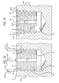
- installation of the threaded insert 20 into the parent material 38 includes aligning the second end 26 of the bushing portion 22 of the threaded insert with the threaded hole 36 in the parent material and screwing the threaded insert into the threaded hole within the parent material.
- the threaded insert 20 is screwed into the parent material 38 until the first end 24 of the bushing portion 22 is approximately 0.25 - 0.76 mm (0.01 - 0.03 inches) below the surface 82 of the parent material.
- the depth to which the threaded insert 20 is screwed into the threaded hole 36 in the parent material 38 may be controlled by the longitudinal placement of the locking portion 46 of the keys 40 during assembly of the threaded insert.
- the locking portion 46 of the keys 40 extends into the male threads 34 on the external surface 32 of the bushing portion 22 of the threaded insert 20, the threaded insert can only be screwed into the threaded hole 36 within the parent material 38 until the locking portion of the keys contacts the parent material. In this manner, the locking portion 46 of the keys 40 may act as a depth-control stop for the threaded insert 20.
- the keys 40 may be driven into the threads 84 within the hole in the parent material.
- the process of driving the keys 40 into the threads 84 within the hole 36 in the parent material 38 causes the locking portion 46 of the keys to broach through the threads of the hole in the parent material.
- the keys 40 may remain in place within the newly broached portion of the threads 84 of the parent material 38, thereby locking the threaded insert 20 in place and preventing the threaded insert from rotating during installation or removal of male threaded fasteners into the female threads 30 (Fig.2) within the central bore 28 of the bushing portion 22.
- the keys 40 may be driven into the threads within the hole in the parent material through the application of several light taps from a tool, such as a hammer or a mallet, directly onto the end surfaces 66 at the first end 55 of the locking portion 46 of the keys.
- the keys 40 may be driven until the end surfaces 66 at the first end 55 of the locking portion 46 of the keys are substantially flush, or below flush, with the surface 82 of the parent material 38.
- the keys 40 may be driven into the threads within the hole 36 in the parent material 38 through the use of an installation tool 86 (FIG. 6) which may include a substantially longitudinal, cylindrical shaft 88.
- the installation tool 86 may include at least a first cylindrical portion 90 and a second cylindrical portion 92 which are substantially longitudinally aligned about the longitudinal axis 94 of the cylindrical shaft 88.
- the first cylindrical portion 90 is positioned at a first end 96 of the installation tool 86.
- the first cylindrical portion 90 may include a first diameter 98 which is slightly smaller than the inside diameter 100 of the female threads 30 within the central bore 28 of the bushing portion 22 of the threaded insert 20 (FIGS. 4a and 4b).
- the first cylindrical portion 90 may also include a first length which is greater than the distance by which the locking portion 46 of the keys 40 in the threaded insert 20 extend from the first end 24 of the bushing portion 22 of the threaded insert (FIGS. 4a and 4b).
- the second cylindrical portion 92 may include a first face 102 which may be positioned adjacent to the first cylindrical portion 90 and a second face 104 on the opposite end of the second cylindrical portion.
- the second cylindrical portion 92 may include a second diameter 106 which is larger than the first diameter 98 of the first cylindrical portion 90 such that the first face 102 is sufficiently large to contact the end surfaces 66 at the first end 55 of the locking portion 46 of each of the keys 40 (FIG. 2) within the threaded insert 20 simultaneously.
- the first cylindrical portion 90 may be inserted into the central bore 28 (FIGS. 4a and 4b) from the first end 24 of the bushing portion 22 of the threaded insert 20 until the first face 102 on the second cylindrical portion 92 contacts the end surfaces 66 at the first end 55 of the locking portion 46 of the keys 40.
- the keys 40 may then be driven through the application of several light taps on the second face 104 of the second cylindrical portion 92 of the installation tool.
- the tendency of the keys to broach into the walls 70 of the slots is reduced compared to threaded inserts of prior art configurations.
- the tendency of the keys 40 to broach into the walls 70 of the slots 42 through the driving of the keys during installation of the threaded insert 20 into the threaded hole 36 in the parent material 38 is reduced compared to threaded inserts of prior art configurations. Therefore, the keys 40 are more easily driven into the parent material 38 during installation of the threaded insert 20 of the present invention than are the keys in threaded inserts of prior art configurations.
Landscapes
- Engineering & Computer Science (AREA)
- General Engineering & Computer Science (AREA)
- Mechanical Engineering (AREA)
- Bolts, Nuts, And Washers (AREA)
- Mutual Connection Of Rods And Tubes (AREA)
- Dowels (AREA)
- Joining Of Building Structures In Genera (AREA)
- Connection Of Plates (AREA)
Claims (17)
- Ein Gewindeeinsatz (20), umfassend :- mindestens einen Keil (40), umfassend außerdem ,- einen im wesentlichen länglichen Zapfenteil (44) umfassend ein erstes Ende (47), ein zweites Ende (49), eine erste Stirnseite (48), eine zweite Stirnseite (50), eine erste Seitenfläche (52) und eine zweite Seitenfläche (54), wobei die erste Stirnseite und die zweite Stirnseite im wesentlichen parallel zueinander sind, wobei die erste Seitenfläche (52) an die erste Stirnfläche (48) und die zweite Stirnfläche (50) angrenzt und wobei die zweite Seitenfläche (54) an die erste Stirnfläche (48) und die zweite Stirnfläche (50) angrenzt, und- einen im wesentlichen länglichen Arretierteil (46), wobei das Arretierteil ein erstes Ende (55), ein zweites Ende (57) und eine Rückseite (56) umfasst, wobei das zweite Ende (57) des Arretierteils (46) angrenzend an das erste Ende (47) des Zapfenteils (44) angeordnet ist, wobei der Zapfenteil (44) und der Arretierteil (46) im wesentlichen in der Längsrichtung fluchten, wobei die Rückseite (56) des Arretierteils (46) im wesentlichen in Längsrichtung mit einem Scheitel (60) der ersten Stirnseite (48) des Zapfenteils (44) fluchtet,- einen Buchsenteil (22), ferner umfassend:- eine im wesentlichen zylindrische Form mit einem ersten Ende (24), einem zweiten Ende (26) und einer sich durch den Buchsenteil erstreckenden zentralen Bohrung (28),- eine Fläche der zentralen Bohrung (28) umfassend Innengewinde (30) über die ganze Länge des Buchsenteils (22),- eine Außenfläche (32) des Buchsenteils (22), umfassend Außengewinde (34) über die Länge des Buchsenteils (22), und- mindestens einen Schlitz (42), der sich im wesentlichen in Längsrichtung über die Länge des Buchsenteils (22) erstreckt und an der Außenfläche (32) des Buchsenteils (22) angeordnet ist, wobei der Schlitz (42) eine Bodenfläche (68) und zwei Wandflächen (70) aufweist, wobei die Wandflächen im wesentlichen parallel zueinander und im wesentlichen rechtwinklig zur Bodenfläche (68) sind , wobei die Tiefe des Schlitzes (42) größer als die Tiefe des Außengewindes (34) auf der Außenfläche (32) ist;- wobei der Zapfenteils (44) von dem mindestens einen Keil (40) in dem mindestens einen Schlitz (42) zum ersten Ende (24) des Hülsenteils hin gerichtet angeordnet ist, wobei die Kante (74) zwischen der ersten Stirnseite (48) und der ersten Seitenfläche (52) des Zapfenteils (44) und die Kante (76) zwischen der ersten Stirnseite (48) und der zweiten Seitenfläche (54) des Zapfenteils (44) in Kontakt mit der Bodenfläche (68) des Schlitzes im Hülsenteil angeordnet sind, wobei die Kante (78) zwischen der zweiten Stirnfläche (50) und der ersten Seitenfläche (52) des Zapfenteils und die Kante (80) zwischen der zweiten Stirnfläche (50) und der zweiten Seitenfläche (54) des Zapfenteils einen Presssitz mit den beiden Wänden (70) im Schlitz (42) des Hülsenteils aufweisen;- wobei sich der Arretierteil (46) des mindestens einen Keils (40) sich jenseits des ersten Endes (24) des Buchsenteils (22) erstreckt; und- wobei die Tiefe des mindestens einen Schlitzes (42) des Buchsenteils ausreicht, damit der Scheitel der zweiten Stirnfläche (50) des Zapfenteils des mindestens einen Keils (42) in einer Tiefe angeordnet ist, die tiefer als der Innendurchmesser des Außengewindes auf der Außenfläche des Buchsenteils ist, wobei der Gewindeeinsatzdadurch gekennzeichnet, dass :- der Zapfenteil (44) ein bogenförmiges Profil aufweist, wobei die erste Stirnfläche (48) eine konkave Oberfläche und die zweite Stirnfläche (50) eine konvexe Oberfläche aufweist,- der Arretierteil (46) einen im wesentlichen dreieckigen Querschnitt aufweist, wobei der dreieckige Querschnitt die Rückseite (56) und zwei abgewinkelte Seiten (58) bildet und die Schnittlinie (62) der zwei abgewinkelten Seiten (58) über die Oberfläche des Zapfenteils (44) herausragt; und- die Schnittlinie (62) der beiden abgewinkelten Seiten (58) des Arretierteils (46) des mindestens einen Keils (40) in einer Tiefe angeordnet ist, die geringer als der Innendurchmesser (72) des Außengewindes (34) auf der Außenoberfläche (32) des Buchsenteils (22) ist.
- Gewindeeinsatz (20) nach Patentanspruch 1, wobei das Außengewinde (34) auf der Außenoberfläche (32) des Buchsenteils (22) so konfiguriert ist, dass es mit einer Gewindebohrung (36) in einem Grundwerkstoff (38) zusammenpasst.
- Gewindeeinsatz (20) nach Patentanspruch 1 oder 2 , wobei das Innengewinde (30) in der Zentralbohrung (28) des Buchsenteils (22) so konfiguriert ist, dass es mit einem Außengewindebefestigungsteil zusammenpasst.
- Gewindeeinsatz (20) nach einem der vorangehenden Patentansprüche, wobei der mindestens eine Keil (40) vier Keile umfasst, wobei die vier Keile über den Umfang des Buchsenteils (22) ungefähr 90° voneinander entfernt angeordnet sind.
- Gewindeeinsatz (20) nach einem der vorangehenden Patentansprüche, wobei :- die erste Seitenfläche (52) des Zapfenteils (44) des mindestens einen Keils im Wesentlichen rechtwinklig zu einer Tangente entlang der ersten Stirnseite (48) des Zapfenteils an der Schnittlinie der ersten Seitenfläche (52) und der ersten Stirnseite (48) ist; und- die zweite Seitenfläche (54) des Zapfenteils (44) des mindestens einen Keils im Wesentlichen rechtwinklig zu einer Tangente entlang der ersten Stirnseite (48) des Zapfenteils an der Schnittlinie der zweiten Seitenfläche (54) und der ersten Stirnseite (48) ist.
- Gewindeeinsatz (20) nach einem der vorangehenden Patentansprüche, wobei die abgewinkelten Seiten (58) des Arretierteils des mindestens einen Keils (40) sich zur zweiten Stirnfläche (50) des Zapfenteils (44) des mindestens einen Keils hin verjüngen.
- Gewindeeinsatz (20) nach Patentanspruch 6, wobei die Verjüngung eine abgewinkelte Verjüngung umfasst.
- Gewindeeinsatz (20) nach Patentanspruch 6, wobei die Verjüngung eine bogenförmige Verjüngung umfasst.
- Gewindeeinsatz (20) nach einem der vorangehenden Patentansprüche, wobei die Schnittlinie (62) der abgewinkelten Seiten 58) des Zapfenteils (46) des mindestens einen Keils im wesentlichen bündig mit dem Außendurchmesser (64) des Außengewindes (34) auf der Außenoberfläche (32) des Buchsenteils (22) angeordnet ist.
- Gewindeeinsatz nach einem der Patentansprüche 1 bis 9, wobei die Schnittlinie (62) der abgewinkelten Seiten (58) des Arretierteils (46) des mindestens einen Keils (40) unten bündig mit dem Außendurchmesser (64) des Außengewindes (34) der Außenfläche (32) des Buchsenteils (22) ist.
- Gewindeeinsatz nach einem der Patentansprüche 1 bis 9, wobei die Schnittlinie (62) der abgewinkelten Seiten (58) des Arretierteils (46) des mindestens einen Keils oben bündig mit dem Außendurchmesser (64) des Außengewindes (34) auf der Außenfläche (32) des Buchsenteils (22) ist.
- Gewindeeinsatz (20) nach einem der vorangehenden Patentansprüche, umfassend außerdem eine Endfläche (66) am ersten Ende (55) des Arretierteils (46) des mindestens einen Keils , wobei die Endfläche (66) im wesentlichen rechtwinklig zur Rückseite (56) und den beiden abgewinkelten Seiten (58) des Arretierteils verläuft.
- Gewindeeinsatz (20) nach einem der vorangehenden Patentansprüche, wobei der ganze Arretierteil (46) des mindestens einen Keils (40) sich über das erste Ende (24) des Buchsenteils (22) erstreckt.
- Gewindeeinsatz (20) nach einem der vorangehenden Patentansprüche, wobei die erste Seitenfläche (52) und die zweite Seitenfläche (54) des Zapfenteils (44) des mindestens einen Keils einen Presssitz mit den beiden Wänden (70) in dem mindestens einen Schlitz (42) des Buchsenteils aufweisen.
- Verfahren zum Einbauen eines Gewindeeinsatzes nach einem der vorangehenden Patentansprüche; wobei das Verfahren folgendes umfasst:- Bereitstellen des mindestens einen Keils (40);- Bereitstellen des Buchsenteils (22);- Anordnung des Zapfenteils (44) von dem mindestens einen Keil (40) in dem mindestens einen Schlitz (42) zum ersten Ende (24) des Hülsenteils (22) hin gerichtet, so dass die Kante (74) zwischen der ersten Stirnseite (48) des Zapfenteils (44) und der ersten Seitenfläche (52) des Zapfenteils (44) und die Kante (76) zwischen der ersten Stirnseite (48) des Zapfenteils (44) und der zweiten Seitenfläche (54) des Zapfenteils in Kontakt mit der Bodenfläche (68) des mindestens eines Schlitzes (42) sind, und der Arretierteil (46) des Keils (40) sich über das erste Ende des Buchsenteils erstreckt; und- Beaufschlagung der zweiten Stirnfläche (50) des Zapfenteils (44) mit einer Kraft in einer Richtung, die im wesentlichen rechtwinklig zur Bodenfläche (68) des mindestens einen Schlitzes (42) verläuft, bis das bogenförmige Profil des Zapfenteils (44) des mindestens einen Keils reduziert wird , wobei ein Scheitel der zweiten Stirnfläche (50) des Zapfenteils in einer Tiefe angeordnet wird, die tiefer als der Innendurchmesser (72) des Außengewindes (34) des Buchsenteils (22) liegt, und ein Presssitz zwischen dem Zapfenteil (44) des mindestens einen Keils und dem mindestens einen Schlitz (42) des Buchsenteils (22) gebildet wird.
- Verfahren nach Patentanspruch 15 , wobei die zweite Stirnfläche (50) des Zapfenteils mit einer Kraft beaufschlagt wird , wobei die Kraftbeaufschlagung solange aufrechterhalten bleibt, bis der Presssitz zwischen den Wänden (70) des mindestens einen Schlitzes (42) des Buchsenteils, der Kante (74) zwischen der ersten Stirnseite (48) des Zapfenteils (44) und der ersten Seitenfläche (52) des Zapfenteils (44) und der Kante (76) zwischen der ersten Stirnseite (48) des Zapfenteils (44) und der zweiten Seitenfläche (54) des Zapfenteils (44) gebildet ist.
- Verfahren nach Patentanspruch 15 , wobei die zweite Stirnfläche (50) des Zapfenteils mit einer Kraft beaufschlagt wird , wobei die Kraftbeaufschlagung solange aufrechterhalten bleibt, bis der Presssitz zwischen den Wänden (70) des mindestens einen Schlitzes des Buchsenteils, der ersten Seitenfläche (52) und der zweiten Seitenfläche (54) gebildet ist.
Applications Claiming Priority (3)
| Application Number | Priority Date | Filing Date | Title |
|---|---|---|---|
| US153167 | 1998-09-15 | ||
| US10/153,167 US6672811B2 (en) | 2002-05-22 | 2002-05-22 | Threaded insert for fasteners |
| PCT/US2003/013260 WO2003100274A1 (en) | 2002-05-22 | 2003-04-29 | Improved threaded insert for fasteners |
Publications (2)
| Publication Number | Publication Date |
|---|---|
| EP1507985A1 EP1507985A1 (de) | 2005-02-23 |
| EP1507985B1 true EP1507985B1 (de) | 2007-03-07 |
Family
ID=29548615
Family Applications (1)
| Application Number | Title | Priority Date | Filing Date |
|---|---|---|---|
| EP03721924A Expired - Lifetime EP1507985B1 (de) | 2002-05-22 | 2003-04-29 | Verbesserter gewindeeinsatz für befestiger |
Country Status (7)
| Country | Link |
|---|---|
| US (5) | US6672811B2 (de) |
| EP (1) | EP1507985B1 (de) |
| AT (1) | ATE356301T1 (de) |
| AU (1) | AU2003225208A1 (de) |
| DE (1) | DE60312324T2 (de) |
| ES (1) | ES2282620T3 (de) |
| WO (1) | WO2003100274A1 (de) |
Families Citing this family (26)
| Publication number | Priority date | Publication date | Assignee | Title |
|---|---|---|---|---|
| US6672811B2 (en) * | 2002-05-22 | 2004-01-06 | Hi-Shear Corporation | Threaded insert for fasteners |
| WO2006015444A2 (en) * | 2004-08-12 | 2006-02-16 | Brian Investments Pty Ltd | A screw threaded member |
| WO2008039334A2 (en) * | 2006-09-22 | 2008-04-03 | Jergens, Inc. | Keylocking threaded insert |
| US7736109B2 (en) * | 2006-12-21 | 2010-06-15 | The Boeing Company | Multi-position ball lock/quick release pin bushing/retainer |
| US20080240883A1 (en) * | 2007-03-30 | 2008-10-02 | Tennant Company | Threaded Insert and Method of Using Same |
| DE102007054798B3 (de) * | 2007-11-16 | 2009-04-16 | Ludwig Hettich & Co. | Verfahren zum Herstellen eines Gewindeeinsatzes mit Innen- und Außengewinde und Gewindeeinsatz |
| US8267630B2 (en) * | 2009-07-13 | 2012-09-18 | United Technologies Corporation | Threaded flanged bushing for fastening applications |
| US8789404B2 (en) | 2009-07-23 | 2014-07-29 | Gkn Sinter Metals, Llc | Compression limiter having retention features |
| DE102009048160B4 (de) * | 2009-10-02 | 2019-05-16 | Böllhoff Verbindungstechnik GmbH | Einformbare Drahtgewindeeinsätze, Bauteil mit einformbarem Drahtgewindeeinsatz sowie Herstellungsverfahren eines Bauteils mit einformbarem Drahtgewindeeinsatz |
| US8992149B2 (en) | 2011-09-01 | 2015-03-31 | Aerojet Rocketdyne Of De, Inc. | Self retaining anti-rotation key |
| USD802407S1 (en) * | 2015-11-11 | 2017-11-14 | Gard Specialist Co., Inc. | Thread repair insert |
| US20160333919A1 (en) * | 2016-07-25 | 2016-11-17 | Caterpillar Inc. | Method and system for installing keylock insert |
| US10677240B2 (en) * | 2017-11-14 | 2020-06-09 | Caterpillar Inc. | Method for remanufacturing fluid end block |
| US11149470B2 (en) * | 2018-02-21 | 2021-10-19 | Mark Thomas Markiewicz | Key rotor for use with manual key switches |
| US10882170B2 (en) | 2018-03-08 | 2021-01-05 | United Technologies Corporation | Key locking stud installation tool |
| USD859973S1 (en) * | 2018-03-14 | 2019-09-17 | Gard Specialists Co., Inc. | Thread repair insert with teeth |
| CN109026969A (zh) * | 2018-05-25 | 2018-12-18 | 廖建飞 | 一种螺栓防松连接组合体 |
| USD918704S1 (en) * | 2019-02-11 | 2021-05-11 | Otto Ganter Gmbh & Co. Kg Normteilefabrik | Bolt |
| USD932293S1 (en) * | 2019-02-20 | 2021-10-05 | Polyplas International Pty Ltd. | End fitting for a rod stiffening component |
| USD907475S1 (en) * | 2019-02-28 | 2021-01-12 | Robert Williams | Bolt head protector |
| USD880284S1 (en) * | 2019-03-11 | 2020-04-07 | Swagelok Company | Face seal fitting nut |
| USD959257S1 (en) * | 2020-02-07 | 2022-08-02 | Norgas Metering Technologies, Inc. | Thread insert |
| US20230030567A1 (en) * | 2021-07-29 | 2023-02-02 | Ming-Cheng Pai | Screw member |
| USD1051710S1 (en) * | 2022-07-13 | 2024-11-19 | Wei In Enterprise Co., Ltd. | Rivet nut |
| USD1102266S1 (en) * | 2022-08-30 | 2025-11-18 | Shinjo Holdings Co., Ltd. | Piercing nut |
| US12399054B1 (en) | 2022-11-14 | 2025-08-26 | Sunsonic, LLC | Clamp on ultrasonic flow meter |
Family Cites Families (30)
| Publication number | Priority date | Publication date | Assignee | Title |
|---|---|---|---|---|
| US1158454A (en) * | 1915-05-06 | 1915-11-02 | Joseph W De Camp | Safety nut-lock. |
| NL189809B (nl) * | 1953-08-10 | Hartwall Kb | Onder een instelbare hoek te bevestigen stootwilhouder. | |
| US2855970A (en) * | 1956-05-07 | 1958-10-14 | Neuschotz Robert | Insert having frictionally retained key which upsets threads of base member |
| US3039508A (en) * | 1957-11-18 | 1962-06-19 | Whitney E Greene | Wedge locked insert |
| US2958358A (en) * | 1958-03-13 | 1960-11-01 | Neuschotz Robert | Threaded element with u-shaped locking key |
| US3105535A (en) * | 1960-08-04 | 1963-10-01 | Iilinois Tool Works Inc | Insert fastener |
| US3103962A (en) * | 1960-11-29 | 1963-09-17 | Robert A Neuschotz | Self-locking threaded insert |
| US3212796A (en) * | 1962-07-16 | 1965-10-19 | Nenschotz Robert | Sealed threaded fitting |
| US3270792A (en) * | 1964-04-20 | 1966-09-06 | Newton Insert Company | Threaded element with carrier part deforming locking key |
| US3328813A (en) * | 1964-04-20 | 1967-07-04 | Neuschotz Robert | Formation of elements having locking keys |
| US3346031A (en) * | 1965-09-21 | 1967-10-10 | Neuschotz Robert | Threaded elements and locking keys therefor |
| US3319688A (en) * | 1965-10-22 | 1967-05-16 | Rosan Eng Corp | Insert having hollow locking pins |
| US3421564A (en) * | 1966-03-07 | 1969-01-14 | Robert Neuschotz | Self-aligning threaded fastener stud |
| US3371697A (en) * | 1966-04-22 | 1968-03-05 | Newton Insert Co | Threaded elements with locking keys |
| US3404717A (en) * | 1966-08-09 | 1968-10-08 | Rosan Jose | Locking pin with cap |
| US3513896A (en) * | 1967-06-26 | 1970-05-26 | Robert Neuschotz | Threaded fasteners having flanges |
| US3472302A (en) * | 1967-12-11 | 1969-10-14 | Jose Rosan Sr | Insert with prism lock pin |
| US3415301A (en) * | 1967-12-13 | 1968-12-10 | Robert Neuschotz | Self-aligning threaded elements |
| US3537118A (en) * | 1969-02-12 | 1970-11-03 | Robert Neuschotz | Formation of fasteners having keys |
| US3667526A (en) * | 1969-02-12 | 1972-06-06 | Robert Neuschotz | Fasteners having locking keys |
| US3650309A (en) * | 1969-02-12 | 1972-03-21 | Robert Neuschotz | Structure and use of fasteners having locking keys |
| US3593560A (en) * | 1969-02-12 | 1971-07-20 | Robert Neuschotz | Formation of locking keys for fasteners |
| US3604105A (en) * | 1969-05-16 | 1971-09-14 | Fridair Ind | Seal assembly for threaded parts and method |
| US4342524A (en) * | 1980-05-28 | 1982-08-03 | Anderson Richard N | Material fastening structure and method |
| US4767249A (en) * | 1986-09-12 | 1988-08-30 | Rexnord Inc. | Self-broaching key |
| US4895485A (en) | 1988-10-05 | 1990-01-23 | Rexnord Holdings Inc. | Locking key for threaded insert |
| US5411357A (en) * | 1993-12-02 | 1995-05-02 | Emhart Inc. | Screw thread locking insert |
| US5647650A (en) * | 1995-04-21 | 1997-07-15 | Metro Industries, Inc. | Modular storage and support assembly |
| US6024523A (en) * | 1997-06-23 | 2000-02-15 | Kaynar Technologies, Inc. | Thread insert with floating nut |
| US6672811B2 (en) * | 2002-05-22 | 2004-01-06 | Hi-Shear Corporation | Threaded insert for fasteners |
-
2002
- 2002-05-22 US US10/153,167 patent/US6672811B2/en not_active Expired - Fee Related
-
2003
- 2003-04-29 AU AU2003225208A patent/AU2003225208A1/en not_active Abandoned
- 2003-04-29 WO PCT/US2003/013260 patent/WO2003100274A1/en not_active Ceased
- 2003-04-29 AT AT03721924T patent/ATE356301T1/de not_active IP Right Cessation
- 2003-04-29 ES ES03721924T patent/ES2282620T3/es not_active Expired - Lifetime
- 2003-04-29 EP EP03721924A patent/EP1507985B1/de not_active Expired - Lifetime
- 2003-04-29 DE DE60312324T patent/DE60312324T2/de not_active Expired - Fee Related
- 2003-11-18 US US10/716,569 patent/US6969221B2/en not_active Expired - Fee Related
-
2005
- 2005-02-04 US US11/051,861 patent/US7234906B2/en not_active Expired - Fee Related
-
2007
- 2007-06-20 US US11/765,996 patent/US7396198B2/en not_active Expired - Fee Related
-
2008
- 2008-05-27 US US12/127,579 patent/US20080226414A1/en not_active Abandoned
Also Published As
| Publication number | Publication date |
|---|---|
| DE60312324T2 (de) | 2007-11-22 |
| US20080226414A1 (en) | 2008-09-18 |
| US20070248433A1 (en) | 2007-10-25 |
| US20040071523A1 (en) | 2004-04-15 |
| ATE356301T1 (de) | 2007-03-15 |
| AU2003225208A1 (en) | 2003-12-12 |
| US20050141982A1 (en) | 2005-06-30 |
| US6969221B2 (en) | 2005-11-29 |
| EP1507985A1 (de) | 2005-02-23 |
| US6672811B2 (en) | 2004-01-06 |
| ES2282620T3 (es) | 2007-10-16 |
| US7396198B2 (en) | 2008-07-08 |
| US7234906B2 (en) | 2007-06-26 |
| DE60312324D1 (de) | 2007-04-19 |
| US20030219325A1 (en) | 2003-11-27 |
| WO2003100274A1 (en) | 2003-12-04 |
Similar Documents
| Publication | Publication Date | Title |
|---|---|---|
| US7396198B2 (en) | Threaded insert for fasteners | |
| US3850215A (en) | Self-locking fasteners | |
| KR100991170B1 (ko) | 맞물림 경사부를 가진 나선형 드라이브 고정구 | |
| CZ163096A3 (en) | Milling and boring machine | |
| DE10326662A1 (de) | Schneideinsatz zum Drehen und Fräsen | |
| EP1239987A1 (de) | Ein schraubenzieher-und senkeinsatz | |
| US20060013671A1 (en) | Threaded insert with multi-lobe broach | |
| TWI757427B (zh) | 具有非正切削幾何的斜進嵌件及斜進刀具 | |
| KR20010012706A (ko) | 스크류를 지지하고 체결하기 위한 신규 시스템 | |
| US4948306A (en) | Drill | |
| US3901066A (en) | Dies for making self-locking screws | |
| US3667526A (en) | Fasteners having locking keys | |
| JP3546915B2 (ja) | 交差穴加工方法および穴加工用工具 | |
| RU2134365C1 (ru) | Пластинчатый сверлящий элемент для самосверлящего крепежного элемента | |
| US9902004B2 (en) | Helical broach | |
| US11471952B2 (en) | Cutting tool having replaceable cutting head and method of securing a replaceable cutting head | |
| US6908253B2 (en) | Split slitter | |
| US3019677A (en) | Rolling dies for threading, pointing and finishing screws | |
| US3910099A (en) | Die member | |
| US7568865B1 (en) | Thread forming tool assembly | |
| US20240117834A1 (en) | Tool and fastener with overhang structures to reduce stripping | |
| US20250367847A1 (en) | Chainsaw guide bar | |
| JP2012035351A (ja) | めねじ加工方法および仕上げ用切削タップ | |
| WO2007131730A1 (en) | Screw or bolt with a recess in their head and driver for engaging the recess and method for producing the head | |
| US20220316513A1 (en) | Fastener |
Legal Events
| Date | Code | Title | Description |
|---|---|---|---|
| PUAI | Public reference made under article 153(3) epc to a published international application that has entered the european phase |
Free format text: ORIGINAL CODE: 0009012 |
|
| 17P | Request for examination filed |
Effective date: 20041130 |
|
| AK | Designated contracting states |
Kind code of ref document: A1 Designated state(s): AT BE BG CH CY CZ DE DK EE ES FI FR GB GR HU IE IT LI LU MC NL PT RO SE SI SK TR |
|
| AX | Request for extension of the european patent |
Extension state: AL LT LV MK |
|
| DAX | Request for extension of the european patent (deleted) | ||
| GRAP | Despatch of communication of intention to grant a patent |
Free format text: ORIGINAL CODE: EPIDOSNIGR1 |
|
| GRAS | Grant fee paid |
Free format text: ORIGINAL CODE: EPIDOSNIGR3 |
|
| GRAA | (expected) grant |
Free format text: ORIGINAL CODE: 0009210 |
|
| AK | Designated contracting states |
Kind code of ref document: B1 Designated state(s): AT BE BG CH CY CZ DE DK EE ES FI FR GB GR HU IE IT LI LU MC NL PT RO SE SI SK TR |
|
| PG25 | Lapsed in a contracting state [announced via postgrant information from national office to epo] |
Ref country code: LI Free format text: LAPSE BECAUSE OF FAILURE TO SUBMIT A TRANSLATION OF THE DESCRIPTION OR TO PAY THE FEE WITHIN THE PRESCRIBED TIME-LIMIT Effective date: 20070307 Ref country code: BE Free format text: LAPSE BECAUSE OF FAILURE TO SUBMIT A TRANSLATION OF THE DESCRIPTION OR TO PAY THE FEE WITHIN THE PRESCRIBED TIME-LIMIT Effective date: 20070307 Ref country code: CH Free format text: LAPSE BECAUSE OF FAILURE TO SUBMIT A TRANSLATION OF THE DESCRIPTION OR TO PAY THE FEE WITHIN THE PRESCRIBED TIME-LIMIT Effective date: 20070307 Ref country code: NL Free format text: LAPSE BECAUSE OF FAILURE TO SUBMIT A TRANSLATION OF THE DESCRIPTION OR TO PAY THE FEE WITHIN THE PRESCRIBED TIME-LIMIT Effective date: 20070307 Ref country code: SI Free format text: LAPSE BECAUSE OF FAILURE TO SUBMIT A TRANSLATION OF THE DESCRIPTION OR TO PAY THE FEE WITHIN THE PRESCRIBED TIME-LIMIT Effective date: 20070307 Ref country code: FI Free format text: LAPSE BECAUSE OF FAILURE TO SUBMIT A TRANSLATION OF THE DESCRIPTION OR TO PAY THE FEE WITHIN THE PRESCRIBED TIME-LIMIT Effective date: 20070307 |
|
| REG | Reference to a national code |
Ref country code: GB Ref legal event code: FG4D |
|
| REG | Reference to a national code |
Ref country code: CH Ref legal event code: EP |
|
| REF | Corresponds to: |
Ref document number: 60312324 Country of ref document: DE Date of ref document: 20070419 Kind code of ref document: P |
|
| REG | Reference to a national code |
Ref country code: IE Ref legal event code: FG4D |
|
| PG25 | Lapsed in a contracting state [announced via postgrant information from national office to epo] |
Ref country code: SE Free format text: LAPSE BECAUSE OF FAILURE TO SUBMIT A TRANSLATION OF THE DESCRIPTION OR TO PAY THE FEE WITHIN THE PRESCRIBED TIME-LIMIT Effective date: 20070607 |
|
| PG25 | Lapsed in a contracting state [announced via postgrant information from national office to epo] |
Ref country code: PT Free format text: LAPSE BECAUSE OF FAILURE TO SUBMIT A TRANSLATION OF THE DESCRIPTION OR TO PAY THE FEE WITHIN THE PRESCRIBED TIME-LIMIT Effective date: 20070807 |
|
| ET | Fr: translation filed | ||
| NLV1 | Nl: lapsed or annulled due to failure to fulfill the requirements of art. 29p and 29m of the patents act | ||
| REG | Reference to a national code |
Ref country code: CH Ref legal event code: PL |
|
| REG | Reference to a national code |
Ref country code: ES Ref legal event code: FG2A Ref document number: 2282620 Country of ref document: ES Kind code of ref document: T3 |
|
| PG25 | Lapsed in a contracting state [announced via postgrant information from national office to epo] |
Ref country code: SK Free format text: LAPSE BECAUSE OF FAILURE TO SUBMIT A TRANSLATION OF THE DESCRIPTION OR TO PAY THE FEE WITHIN THE PRESCRIBED TIME-LIMIT Effective date: 20070307 |
|
| PG25 | Lapsed in a contracting state [announced via postgrant information from national office to epo] |
Ref country code: CZ Free format text: LAPSE BECAUSE OF FAILURE TO SUBMIT A TRANSLATION OF THE DESCRIPTION OR TO PAY THE FEE WITHIN THE PRESCRIBED TIME-LIMIT Effective date: 20070307 Ref country code: RO Free format text: LAPSE BECAUSE OF FAILURE TO SUBMIT A TRANSLATION OF THE DESCRIPTION OR TO PAY THE FEE WITHIN THE PRESCRIBED TIME-LIMIT Effective date: 20070307 |
|
| PLBE | No opposition filed within time limit |
Free format text: ORIGINAL CODE: 0009261 |
|
| STAA | Information on the status of an ep patent application or granted ep patent |
Free format text: STATUS: NO OPPOSITION FILED WITHIN TIME LIMIT |
|
| PG25 | Lapsed in a contracting state [announced via postgrant information from national office to epo] |
Ref country code: DK Free format text: LAPSE BECAUSE OF FAILURE TO SUBMIT A TRANSLATION OF THE DESCRIPTION OR TO PAY THE FEE WITHIN THE PRESCRIBED TIME-LIMIT Effective date: 20070307 |
|
| 26N | No opposition filed |
Effective date: 20071210 |
|
| PG25 | Lapsed in a contracting state [announced via postgrant information from national office to epo] |
Ref country code: GR Free format text: LAPSE BECAUSE OF FAILURE TO SUBMIT A TRANSLATION OF THE DESCRIPTION OR TO PAY THE FEE WITHIN THE PRESCRIBED TIME-LIMIT Effective date: 20070608 |
|
| PG25 | Lapsed in a contracting state [announced via postgrant information from national office to epo] |
Ref country code: IE Free format text: LAPSE BECAUSE OF NON-PAYMENT OF DUE FEES Effective date: 20070430 |
|
| PG25 | Lapsed in a contracting state [announced via postgrant information from national office to epo] |
Ref country code: EE Free format text: LAPSE BECAUSE OF FAILURE TO SUBMIT A TRANSLATION OF THE DESCRIPTION OR TO PAY THE FEE WITHIN THE PRESCRIBED TIME-LIMIT Effective date: 20070307 |
|
| PG25 | Lapsed in a contracting state [announced via postgrant information from national office to epo] |
Ref country code: MC Free format text: LAPSE BECAUSE OF NON-PAYMENT OF DUE FEES Effective date: 20070430 |
|
| PG25 | Lapsed in a contracting state [announced via postgrant information from national office to epo] |
Ref country code: CY Free format text: LAPSE BECAUSE OF FAILURE TO SUBMIT A TRANSLATION OF THE DESCRIPTION OR TO PAY THE FEE WITHIN THE PRESCRIBED TIME-LIMIT Effective date: 20070307 |
|
| PGFP | Annual fee paid to national office [announced via postgrant information from national office to epo] |
Ref country code: ES Payment date: 20090427 Year of fee payment: 7 |
|
| PG25 | Lapsed in a contracting state [announced via postgrant information from national office to epo] |
Ref country code: BG Free format text: LAPSE BECAUSE OF FAILURE TO SUBMIT A TRANSLATION OF THE DESCRIPTION OR TO PAY THE FEE WITHIN THE PRESCRIBED TIME-LIMIT Effective date: 20070607 Ref country code: LU Free format text: LAPSE BECAUSE OF NON-PAYMENT OF DUE FEES Effective date: 20070429 |
|
| PGFP | Annual fee paid to national office [announced via postgrant information from national office to epo] |
Ref country code: AT Payment date: 20090401 Year of fee payment: 7 Ref country code: DE Payment date: 20090429 Year of fee payment: 7 Ref country code: FR Payment date: 20090417 Year of fee payment: 7 Ref country code: IT Payment date: 20090427 Year of fee payment: 7 Ref country code: TR Payment date: 20090403 Year of fee payment: 7 |
|
| PG25 | Lapsed in a contracting state [announced via postgrant information from national office to epo] |
Ref country code: HU Free format text: LAPSE BECAUSE OF FAILURE TO SUBMIT A TRANSLATION OF THE DESCRIPTION OR TO PAY THE FEE WITHIN THE PRESCRIBED TIME-LIMIT Effective date: 20070908 |
|
| PGFP | Annual fee paid to national office [announced via postgrant information from national office to epo] |
Ref country code: GB Payment date: 20090429 Year of fee payment: 7 |
|
| GBPC | Gb: european patent ceased through non-payment of renewal fee |
Effective date: 20100429 |
|
| REG | Reference to a national code |
Ref country code: FR Ref legal event code: ST Effective date: 20101230 |
|
| PG25 | Lapsed in a contracting state [announced via postgrant information from national office to epo] |
Ref country code: AT Free format text: LAPSE BECAUSE OF NON-PAYMENT OF DUE FEES Effective date: 20100429 |
|
| PG25 | Lapsed in a contracting state [announced via postgrant information from national office to epo] |
Ref country code: DE Free format text: LAPSE BECAUSE OF NON-PAYMENT OF DUE FEES Effective date: 20101103 |
|
| PG25 | Lapsed in a contracting state [announced via postgrant information from national office to epo] |
Ref country code: GB Free format text: LAPSE BECAUSE OF NON-PAYMENT OF DUE FEES Effective date: 20100429 Ref country code: IT Free format text: LAPSE BECAUSE OF NON-PAYMENT OF DUE FEES Effective date: 20100429 |
|
| REG | Reference to a national code |
Ref country code: ES Ref legal event code: FD2A Effective date: 20110712 |
|
| PG25 | Lapsed in a contracting state [announced via postgrant information from national office to epo] |
Ref country code: ES Free format text: LAPSE BECAUSE OF NON-PAYMENT OF DUE FEES Effective date: 20110630 |
|
| PG25 | Lapsed in a contracting state [announced via postgrant information from national office to epo] |
Ref country code: ES Free format text: LAPSE BECAUSE OF NON-PAYMENT OF DUE FEES Effective date: 20100430 |
|
| PG25 | Lapsed in a contracting state [announced via postgrant information from national office to epo] |
Ref country code: FR Free format text: LAPSE BECAUSE OF NON-PAYMENT OF DUE FEES Effective date: 20100430 |
|
| PG25 | Lapsed in a contracting state [announced via postgrant information from national office to epo] |
Ref country code: TR Free format text: LAPSE BECAUSE OF NON-PAYMENT OF DUE FEES Effective date: 20100429 |