EP1507895B1 - Rundläufermaschine für cvd-beschichtungen - Google Patents
Rundläufermaschine für cvd-beschichtungen Download PDFInfo
- Publication number
- EP1507895B1 EP1507895B1 EP03755134A EP03755134A EP1507895B1 EP 1507895 B1 EP1507895 B1 EP 1507895B1 EP 03755134 A EP03755134 A EP 03755134A EP 03755134 A EP03755134 A EP 03755134A EP 1507895 B1 EP1507895 B1 EP 1507895B1
- Authority
- EP
- European Patent Office
- Prior art keywords
- pump
- rotary machine
- pump device
- evacuation
- pumping
- Prior art date
- Legal status (The legal status is an assumption and is not a legal conclusion. Google has not performed a legal analysis and makes no representation as to the accuracy of the status listed.)
- Expired - Lifetime
Links
Images




Classifications
-
- C—CHEMISTRY; METALLURGY
- C23—COATING METALLIC MATERIAL; COATING MATERIAL WITH METALLIC MATERIAL; CHEMICAL SURFACE TREATMENT; DIFFUSION TREATMENT OF METALLIC MATERIAL; COATING BY VACUUM EVAPORATION, BY SPUTTERING, BY ION IMPLANTATION OR BY CHEMICAL VAPOUR DEPOSITION, IN GENERAL; INHIBITING CORROSION OF METALLIC MATERIAL OR INCRUSTATION IN GENERAL
- C23C—COATING METALLIC MATERIAL; COATING MATERIAL WITH METALLIC MATERIAL; SURFACE TREATMENT OF METALLIC MATERIAL BY DIFFUSION INTO THE SURFACE, BY CHEMICAL CONVERSION OR SUBSTITUTION; COATING BY VACUUM EVAPORATION, BY SPUTTERING, BY ION IMPLANTATION OR BY CHEMICAL VAPOUR DEPOSITION, IN GENERAL
- C23C16/00—Chemical coating by decomposition of gaseous compounds, without leaving reaction products of surface material in the coating, i.e. chemical vapour deposition [CVD] processes
- C23C16/44—Chemical coating by decomposition of gaseous compounds, without leaving reaction products of surface material in the coating, i.e. chemical vapour deposition [CVD] processes characterised by the method of coating
- C23C16/54—Apparatus specially adapted for continuous coating
-
- B—PERFORMING OPERATIONS; TRANSPORTING
- B08—CLEANING
- B08B—CLEANING IN GENERAL; PREVENTION OF FOULING IN GENERAL
- B08B7/00—Cleaning by methods not provided for in a single other subclass or a single group in this subclass
-
- B—PERFORMING OPERATIONS; TRANSPORTING
- B29—WORKING OF PLASTICS; WORKING OF SUBSTANCES IN A PLASTIC STATE IN GENERAL
- B29C—SHAPING OR JOINING OF PLASTICS; SHAPING OF MATERIAL IN A PLASTIC STATE, NOT OTHERWISE PROVIDED FOR; AFTER-TREATMENT OF THE SHAPED PRODUCTS, e.g. REPAIRING
- B29C49/00—Blow-moulding, i.e. blowing a preform or parison to a desired shape within a mould; Apparatus therefor
- B29C49/42—Component parts, details or accessories; Auxiliary operations
- B29C49/4205—Handling means, e.g. transfer, loading or discharging means
- B29C49/42069—Means explicitly adapted for transporting blown article
-
- B—PERFORMING OPERATIONS; TRANSPORTING
- B65—CONVEYING; PACKING; STORING; HANDLING THIN OR FILAMENTARY MATERIAL
- B65D—CONTAINERS FOR STORAGE OR TRANSPORT OF ARTICLES OR MATERIALS, e.g. BAGS, BARRELS, BOTTLES, BOXES, CANS, CARTONS, CRATES, DRUMS, JARS, TANKS, HOPPERS, FORWARDING CONTAINERS; ACCESSORIES, CLOSURES, OR FITTINGS THEREFOR; PACKAGING ELEMENTS; PACKAGES
- B65D23/00—Details of bottles or jars not otherwise provided for
- B65D23/02—Linings or internal coatings
-
- C—CHEMISTRY; METALLURGY
- C03—GLASS; MINERAL OR SLAG WOOL
- C03C—CHEMICAL COMPOSITION OF GLASSES, GLAZES OR VITREOUS ENAMELS; SURFACE TREATMENT OF GLASS; SURFACE TREATMENT OF FIBRES OR FILAMENTS MADE FROM GLASS, MINERALS OR SLAGS; JOINING GLASS TO GLASS OR OTHER MATERIALS
- C03C17/00—Surface treatment of glass, not in the form of fibres or filaments, by coating
- C03C17/001—General methods for coating; Devices therefor
- C03C17/003—General methods for coating; Devices therefor for hollow ware, e.g. containers
- C03C17/004—Coating the inside
-
- C—CHEMISTRY; METALLURGY
- C08—ORGANIC MACROMOLECULAR COMPOUNDS; THEIR PREPARATION OR CHEMICAL WORKING-UP; COMPOSITIONS BASED THEREON
- C08J—WORKING-UP; GENERAL PROCESSES OF COMPOUNDING; AFTER-TREATMENT NOT COVERED BY SUBCLASSES C08B, C08C, C08F, C08G or C08H
- C08J9/00—Working-up of macromolecular substances to porous or cellular articles or materials; After-treatment thereof
- C08J9/0004—Use of compounding ingredients, the chemical constitution of which is unknown, broadly defined, or irrelevant
-
- C—CHEMISTRY; METALLURGY
- C23—COATING METALLIC MATERIAL; COATING MATERIAL WITH METALLIC MATERIAL; CHEMICAL SURFACE TREATMENT; DIFFUSION TREATMENT OF METALLIC MATERIAL; COATING BY VACUUM EVAPORATION, BY SPUTTERING, BY ION IMPLANTATION OR BY CHEMICAL VAPOUR DEPOSITION, IN GENERAL; INHIBITING CORROSION OF METALLIC MATERIAL OR INCRUSTATION IN GENERAL
- C23C—COATING METALLIC MATERIAL; COATING MATERIAL WITH METALLIC MATERIAL; SURFACE TREATMENT OF METALLIC MATERIAL BY DIFFUSION INTO THE SURFACE, BY CHEMICAL CONVERSION OR SUBSTITUTION; COATING BY VACUUM EVAPORATION, BY SPUTTERING, BY ION IMPLANTATION OR BY CHEMICAL VAPOUR DEPOSITION, IN GENERAL
- C23C16/00—Chemical coating by decomposition of gaseous compounds, without leaving reaction products of surface material in the coating, i.e. chemical vapour deposition [CVD] processes
- C23C16/04—Coating on selected surface areas, e.g. using masks
- C23C16/045—Coating cavities or hollow spaces, e.g. interior of tubes; Infiltration of porous substrates
-
- C—CHEMISTRY; METALLURGY
- C23—COATING METALLIC MATERIAL; COATING MATERIAL WITH METALLIC MATERIAL; CHEMICAL SURFACE TREATMENT; DIFFUSION TREATMENT OF METALLIC MATERIAL; COATING BY VACUUM EVAPORATION, BY SPUTTERING, BY ION IMPLANTATION OR BY CHEMICAL VAPOUR DEPOSITION, IN GENERAL; INHIBITING CORROSION OF METALLIC MATERIAL OR INCRUSTATION IN GENERAL
- C23C—COATING METALLIC MATERIAL; COATING MATERIAL WITH METALLIC MATERIAL; SURFACE TREATMENT OF METALLIC MATERIAL BY DIFFUSION INTO THE SURFACE, BY CHEMICAL CONVERSION OR SUBSTITUTION; COATING BY VACUUM EVAPORATION, BY SPUTTERING, BY ION IMPLANTATION OR BY CHEMICAL VAPOUR DEPOSITION, IN GENERAL
- C23C16/00—Chemical coating by decomposition of gaseous compounds, without leaving reaction products of surface material in the coating, i.e. chemical vapour deposition [CVD] processes
- C23C16/22—Chemical coating by decomposition of gaseous compounds, without leaving reaction products of surface material in the coating, i.e. chemical vapour deposition [CVD] processes characterised by the deposition of inorganic material, other than metallic material
- C23C16/30—Deposition of compounds, mixtures or solid solutions, e.g. borides, carbides, nitrides
- C23C16/40—Oxides
- C23C16/401—Oxides containing silicon
-
- C—CHEMISTRY; METALLURGY
- C23—COATING METALLIC MATERIAL; COATING MATERIAL WITH METALLIC MATERIAL; CHEMICAL SURFACE TREATMENT; DIFFUSION TREATMENT OF METALLIC MATERIAL; COATING BY VACUUM EVAPORATION, BY SPUTTERING, BY ION IMPLANTATION OR BY CHEMICAL VAPOUR DEPOSITION, IN GENERAL; INHIBITING CORROSION OF METALLIC MATERIAL OR INCRUSTATION IN GENERAL
- C23C—COATING METALLIC MATERIAL; COATING MATERIAL WITH METALLIC MATERIAL; SURFACE TREATMENT OF METALLIC MATERIAL BY DIFFUSION INTO THE SURFACE, BY CHEMICAL CONVERSION OR SUBSTITUTION; COATING BY VACUUM EVAPORATION, BY SPUTTERING, BY ION IMPLANTATION OR BY CHEMICAL VAPOUR DEPOSITION, IN GENERAL
- C23C16/00—Chemical coating by decomposition of gaseous compounds, without leaving reaction products of surface material in the coating, i.e. chemical vapour deposition [CVD] processes
- C23C16/44—Chemical coating by decomposition of gaseous compounds, without leaving reaction products of surface material in the coating, i.e. chemical vapour deposition [CVD] processes characterised by the method of coating
- C23C16/4412—Details relating to the exhausts, e.g. pumps, filters, scrubbers, particle traps
-
- C—CHEMISTRY; METALLURGY
- C23—COATING METALLIC MATERIAL; COATING MATERIAL WITH METALLIC MATERIAL; CHEMICAL SURFACE TREATMENT; DIFFUSION TREATMENT OF METALLIC MATERIAL; COATING BY VACUUM EVAPORATION, BY SPUTTERING, BY ION IMPLANTATION OR BY CHEMICAL VAPOUR DEPOSITION, IN GENERAL; INHIBITING CORROSION OF METALLIC MATERIAL OR INCRUSTATION IN GENERAL
- C23C—COATING METALLIC MATERIAL; COATING MATERIAL WITH METALLIC MATERIAL; SURFACE TREATMENT OF METALLIC MATERIAL BY DIFFUSION INTO THE SURFACE, BY CHEMICAL CONVERSION OR SUBSTITUTION; COATING BY VACUUM EVAPORATION, BY SPUTTERING, BY ION IMPLANTATION OR BY CHEMICAL VAPOUR DEPOSITION, IN GENERAL
- C23C16/00—Chemical coating by decomposition of gaseous compounds, without leaving reaction products of surface material in the coating, i.e. chemical vapour deposition [CVD] processes
- C23C16/44—Chemical coating by decomposition of gaseous compounds, without leaving reaction products of surface material in the coating, i.e. chemical vapour deposition [CVD] processes characterised by the method of coating
- C23C16/458—Chemical coating by decomposition of gaseous compounds, without leaving reaction products of surface material in the coating, i.e. chemical vapour deposition [CVD] processes characterised by the method of coating characterised by the method used for supporting substrates in the reaction chamber
-
- C—CHEMISTRY; METALLURGY
- C23—COATING METALLIC MATERIAL; COATING MATERIAL WITH METALLIC MATERIAL; CHEMICAL SURFACE TREATMENT; DIFFUSION TREATMENT OF METALLIC MATERIAL; COATING BY VACUUM EVAPORATION, BY SPUTTERING, BY ION IMPLANTATION OR BY CHEMICAL VAPOUR DEPOSITION, IN GENERAL; INHIBITING CORROSION OF METALLIC MATERIAL OR INCRUSTATION IN GENERAL
- C23C—COATING METALLIC MATERIAL; COATING MATERIAL WITH METALLIC MATERIAL; SURFACE TREATMENT OF METALLIC MATERIAL BY DIFFUSION INTO THE SURFACE, BY CHEMICAL CONVERSION OR SUBSTITUTION; COATING BY VACUUM EVAPORATION, BY SPUTTERING, BY ION IMPLANTATION OR BY CHEMICAL VAPOUR DEPOSITION, IN GENERAL
- C23C16/00—Chemical coating by decomposition of gaseous compounds, without leaving reaction products of surface material in the coating, i.e. chemical vapour deposition [CVD] processes
- C23C16/44—Chemical coating by decomposition of gaseous compounds, without leaving reaction products of surface material in the coating, i.e. chemical vapour deposition [CVD] processes characterised by the method of coating
- C23C16/50—Chemical coating by decomposition of gaseous compounds, without leaving reaction products of surface material in the coating, i.e. chemical vapour deposition [CVD] processes characterised by the method of coating using electric discharges
- C23C16/511—Chemical coating by decomposition of gaseous compounds, without leaving reaction products of surface material in the coating, i.e. chemical vapour deposition [CVD] processes characterised by the method of coating using electric discharges using microwave discharges
-
- H—ELECTRICITY
- H01—ELECTRIC ELEMENTS
- H01J—ELECTRIC DISCHARGE TUBES OR DISCHARGE LAMPS
- H01J37/00—Discharge tubes with provision for introducing objects or material to be exposed to the discharge, e.g. for the purpose of examination or processing thereof
- H01J37/32—Gas-filled discharge tubes
- H01J37/32431—Constructional details of the reactor
- H01J37/32733—Means for moving the material to be treated
-
- B—PERFORMING OPERATIONS; TRANSPORTING
- B05—SPRAYING OR ATOMISING IN GENERAL; APPLYING FLUENT MATERIALS TO SURFACES, IN GENERAL
- B05D—PROCESSES FOR APPLYING FLUENT MATERIALS TO SURFACES, IN GENERAL
- B05D1/00—Processes for applying liquids or other fluent materials
- B05D1/62—Plasma-deposition of organic layers
-
- B—PERFORMING OPERATIONS; TRANSPORTING
- B29—WORKING OF PLASTICS; WORKING OF SUBSTANCES IN A PLASTIC STATE IN GENERAL
- B29C—SHAPING OR JOINING OF PLASTICS; SHAPING OF MATERIAL IN A PLASTIC STATE, NOT OTHERWISE PROVIDED FOR; AFTER-TREATMENT OF THE SHAPED PRODUCTS, e.g. REPAIRING
- B29C2791/00—Shaping characteristics in general
- B29C2791/001—Shaping in several steps
-
- B—PERFORMING OPERATIONS; TRANSPORTING
- B29—WORKING OF PLASTICS; WORKING OF SUBSTANCES IN A PLASTIC STATE IN GENERAL
- B29C—SHAPING OR JOINING OF PLASTICS; SHAPING OF MATERIAL IN A PLASTIC STATE, NOT OTHERWISE PROVIDED FOR; AFTER-TREATMENT OF THE SHAPED PRODUCTS, e.g. REPAIRING
- B29C49/00—Blow-moulding, i.e. blowing a preform or parison to a desired shape within a mould; Apparatus therefor
- B29C49/42—Component parts, details or accessories; Auxiliary operations
- B29C49/4205—Handling means, e.g. transfer, loading or discharging means
- B29C49/42073—Grippers
-
- B—PERFORMING OPERATIONS; TRANSPORTING
- B29—WORKING OF PLASTICS; WORKING OF SUBSTANCES IN A PLASTIC STATE IN GENERAL
- B29C—SHAPING OR JOINING OF PLASTICS; SHAPING OF MATERIAL IN A PLASTIC STATE, NOT OTHERWISE PROVIDED FOR; AFTER-TREATMENT OF THE SHAPED PRODUCTS, e.g. REPAIRING
- B29C49/00—Blow-moulding, i.e. blowing a preform or parison to a desired shape within a mould; Apparatus therefor
- B29C49/42—Component parts, details or accessories; Auxiliary operations
- B29C49/4205—Handling means, e.g. transfer, loading or discharging means
- B29C49/42073—Grippers
- B29C49/42075—Grippers with pivoting clamps
-
- B—PERFORMING OPERATIONS; TRANSPORTING
- B29—WORKING OF PLASTICS; WORKING OF SUBSTANCES IN A PLASTIC STATE IN GENERAL
- B29C—SHAPING OR JOINING OF PLASTICS; SHAPING OF MATERIAL IN A PLASTIC STATE, NOT OTHERWISE PROVIDED FOR; AFTER-TREATMENT OF THE SHAPED PRODUCTS, e.g. REPAIRING
- B29C49/00—Blow-moulding, i.e. blowing a preform or parison to a desired shape within a mould; Apparatus therefor
- B29C49/42—Component parts, details or accessories; Auxiliary operations
- B29C49/4205—Handling means, e.g. transfer, loading or discharging means
- B29C49/42093—Transporting apparatus, e.g. slides, wheels or conveyors
- B29C49/42095—Rotating wheels or stars
-
- B—PERFORMING OPERATIONS; TRANSPORTING
- B29—WORKING OF PLASTICS; WORKING OF SUBSTANCES IN A PLASTIC STATE IN GENERAL
- B29C—SHAPING OR JOINING OF PLASTICS; SHAPING OF MATERIAL IN A PLASTIC STATE, NOT OTHERWISE PROVIDED FOR; AFTER-TREATMENT OF THE SHAPED PRODUCTS, e.g. REPAIRING
- B29C49/00—Blow-moulding, i.e. blowing a preform or parison to a desired shape within a mould; Apparatus therefor
- B29C49/42—Component parts, details or accessories; Auxiliary operations
- B29C49/4205—Handling means, e.g. transfer, loading or discharging means
- B29C49/42093—Transporting apparatus, e.g. slides, wheels or conveyors
- B29C49/42105—Transporting apparatus, e.g. slides, wheels or conveyors for discontinuous or batch transport
-
- B—PERFORMING OPERATIONS; TRANSPORTING
- B29—WORKING OF PLASTICS; WORKING OF SUBSTANCES IN A PLASTIC STATE IN GENERAL
- B29C—SHAPING OR JOINING OF PLASTICS; SHAPING OF MATERIAL IN A PLASTIC STATE, NOT OTHERWISE PROVIDED FOR; AFTER-TREATMENT OF THE SHAPED PRODUCTS, e.g. REPAIRING
- B29C49/00—Blow-moulding, i.e. blowing a preform or parison to a desired shape within a mould; Apparatus therefor
- B29C49/42—Component parts, details or accessories; Auxiliary operations
- B29C49/4205—Handling means, e.g. transfer, loading or discharging means
- B29C49/42113—Means for manipulating the objects' position or orientation
- B29C49/42115—Inversion, e.g. turning preform upside down
-
- B—PERFORMING OPERATIONS; TRANSPORTING
- B29—WORKING OF PLASTICS; WORKING OF SUBSTANCES IN A PLASTIC STATE IN GENERAL
- B29C—SHAPING OR JOINING OF PLASTICS; SHAPING OF MATERIAL IN A PLASTIC STATE, NOT OTHERWISE PROVIDED FOR; AFTER-TREATMENT OF THE SHAPED PRODUCTS, e.g. REPAIRING
- B29C49/00—Blow-moulding, i.e. blowing a preform or parison to a desired shape within a mould; Apparatus therefor
- B29C49/42—Component parts, details or accessories; Auxiliary operations
- B29C49/42384—Safety, e.g. operator safety
-
- B—PERFORMING OPERATIONS; TRANSPORTING
- B29—WORKING OF PLASTICS; WORKING OF SUBSTANCES IN A PLASTIC STATE IN GENERAL
- B29C—SHAPING OR JOINING OF PLASTICS; SHAPING OF MATERIAL IN A PLASTIC STATE, NOT OTHERWISE PROVIDED FOR; AFTER-TREATMENT OF THE SHAPED PRODUCTS, e.g. REPAIRING
- B29C49/00—Blow-moulding, i.e. blowing a preform or parison to a desired shape within a mould; Apparatus therefor
- B29C49/42—Component parts, details or accessories; Auxiliary operations
- B29C49/64—Heating or cooling preforms, parisons or blown articles
- B29C49/68—Ovens specially adapted for heating preforms or parisons
- B29C49/6835—Ovens specially adapted for heating preforms or parisons using reflectors
-
- B—PERFORMING OPERATIONS; TRANSPORTING
- B65—CONVEYING; PACKING; STORING; HANDLING THIN OR FILAMENTARY MATERIAL
- B65G—TRANSPORT OR STORAGE DEVICES, e.g. CONVEYORS FOR LOADING OR TIPPING, SHOP CONVEYOR SYSTEMS OR PNEUMATIC TUBE CONVEYORS
- B65G2201/00—Indexing codes relating to handling devices, e.g. conveyors, characterised by the type of product or load being conveyed or handled
- B65G2201/02—Articles
- B65G2201/0235—Containers
- B65G2201/0244—Bottles
-
- C—CHEMISTRY; METALLURGY
- C08—ORGANIC MACROMOLECULAR COMPOUNDS; THEIR PREPARATION OR CHEMICAL WORKING-UP; COMPOSITIONS BASED THEREON
- C08J—WORKING-UP; GENERAL PROCESSES OF COMPOUNDING; AFTER-TREATMENT NOT COVERED BY SUBCLASSES C08B, C08C, C08F, C08G or C08H
- C08J2300/00—Characterised by the use of unspecified polymers
- C08J2300/14—Water soluble or water swellable polymers, e.g. aqueous gels
Definitions
- the invention relates to a rotary machine and a method for the treatment of workpieces, in particular a rotary machine and a method for CVD coatings with rotating pumping devices.
- plastic containers generally have a relatively high permeation of gases. Over time, carbon dioxide escapes from carbonated drinks stored in such containers, causing the drinks to quickly become stale. In addition, oxygen can also penetrate through the plastic and initiate oxidation processes in foods stored therein, which also significantly shortens their shelf life.
- plastic containers also have many advantages, such as low weight, low unit price and stability against mechanical stresses due to the high elasticity compared to glass containers.
- plastic container with Barrier coatings or provide diffusion barrier layers, which improve the barrier effect of such containers by orders of magnitude.
- Such coatings may even be useful on glass containers, for example in the field of pharmaceutical packaging, for example, the migration of alkali ions from the glass container wall can be prevented in the interior by a silicon oxide barrier.
- CVD chemical vapor deposition
- the deposition of a layer occurs via a reactive chemical gas mixture which surrounds the surface to be coated. From mixtures of different gases, an almost unlimited variety of possible layers can be generated. In this case, among other things oxide layers, such as the already mentioned SiO 2 layers, have proven to be diffusion barriers.
- a chemically reactive gas mixture can be generated for the CVD coating thermally or by ionization of the process gases, for example by entry of electromagnetic energy. Since plastics are generally not sufficiently thermally stable or have low softening points, CVD coating under the influence of temperature is unsuitable for the coating of plastic surfaces. Here, however, offers the possibility of plasma-assisted CVD coating (PECVD). Since plasma also causes heating of the surface to be coated, plasma pulsed CVD coating (PICVD) is particularly suitable.
- PECVD plasma-assisted CVD coating
- PICVD plasma pulsed CVD coating
- a rotary apparatus is advantageous in which the coating stations for the workpieces to be coated rotate on a circular path.
- a continuous coating sequence can be realized in which the individual processing phases are assigned during circulation to certain circle segments or angular ranges.
- Such a device is among others from the DE 199 16 478 A1 and the WO 00 58631 known.
- the reactors arranged on a rotary reactor must be evacuated to the plasma discharge pressure, wherein the evacuation is carried out by means of pumps connected in parallel, which are connected to the reactors via ring distributors.
- the evacuation runs in stages, with the individual stages of different pumps or pumping systems assigned. With each pumping operation, several reactors can be evacuated simultaneously.
- this conveyor carousel has several disadvantages. Among other things, it has proven to be beneficial not to pump the coating stations with a single pumping device. In order to achieve fast low pressures, rather a multi-stage pumping at different pressure levels is favorable, while the in WO 00 58631 disclosed device provides only one connection of a treatment station, each with a pressure source.
- a distribution device with rotating, airtight connections causes an arrangement of this device on the axis of rotation of the conveyor carousel, while the coating stations are mounted on the circumference of the carousel.
- This will require long vacuum connection lines from the manifold to the treatment stations.
- this is detrimental to the conductance of the vacuum system and thus adversely affects the duration of the necessary evacuation time.
- a joint connection of two treatment stations belonging to a group at a common pressure source can lead to a crosstalk of the treatment stations connected to one another via the pressure source, if these are at different pressure levels.
- the invention is therefore based on the object to provide a rotary machine and a method for CVD coatings, which allows a particularly effective and fast coating of workpieces.
- the pumping device is transported to the conveyor carousel, can be dispensed with in the connection of this pumping device with the treatment stations on a vacuum-tight rotary feeder. Also, the leads can be kept short by an otherwise unrealizable when using a rotary feeder near the pumping device to the treatment stations and provided with large cross-sections.
- the treatment stations can then be ventilated and the workpieces removed.
- connection of the one or more pumping devices to the treatment stations can be advantageously produced by means of a distributor device.
- This can advantageously comprise a distributor, in particular in the form of a ring distributor, to which the pumping devices and connecting lines to the coating chambers are connected.
- connection of a particular treatment station with a pumping device can be done by the distributor device in dependence on the angular position of the treatment station on the conveyor carousel.
- the distributor device may comprise control valves.
- the connecting of the treatment stations with the first or second pumping device can thus be effected by switching the control valves, wherein the valves are opened or closed at corresponding angular positions and thus establish the connection with the pumping device or the distributor.
- the rotary device according to the invention also has at least one stationary second pumping device or external conveying device.
- the treatment stations can be connected for evacuation with this second pumping device.
- the second, stationary pumping device as well as the first, co-rotating pumping device can be connected to at least one, in particular also the same distributor device for connecting the treatment stations to the second pumping device.
- the evacuation of the treatment stations is preferably carried out in at least two steps or evacuation phases, wherein between the steps is preferably switched between different pumping devices.
- the first and second pumping means are adapted for different pressure ranges. These can then be sequentially connected, for example, during the evacuation after descending pressure ranges with the treatment stations, so that each pumping device operates in the optimal pressure range for them.
- the co-rotating first pumping device is optimized for a lower pressure range than the second pumping device, since the suction power decreases with decreasing pressure while maintaining the same pumping speed.
- good conductance values of the supply lines are important for short pump-down times, especially at low pressures, in order to obtain the greatest possible effective pumping speed.
- the pumping capacity can therefore be increased according to a further embodiment of the invention in that the rotary device comprises at least two similar or equivalent pumping devices. These similar or equivalent pumping means may be co-rotating first and / or fixed second pumping means. The evacuation of the treatment stations is then according to this embodiment of the invention with the same or equivalent pumping devices during at least one evacuation phase.
- one of the similar or equivalent pumping devices is connected to at least one treatment station for the duration of the at least one evacuation phase.
- a distributor device for connecting the treatment stations with the pumping means is provided, which in each case one of the similar or equivalent pumping devices with at least one treatment station for the duration of the evacuation phase connects.
- a treatment station or a group of treatment stations is connected on entry into an evacuation phase associated with a circle segment of a first of the same pumping devices.
- the next treatment station or group of treatment station is then connected to the second of the similar pumping devices when entering the circular segment.
- This sequence of connection with the pumping devices can then advantageously be continued cyclically.
- p 0 denotes the pressure before the line and p 2 the pressure at the pump end of the line.
- ⁇ is the dynamic viscosity of the gas called.
- the sizes d and 1 denote the diameter and the length of the pipe. From equation 3 it can be seen that the conductance of the vacuum lines depends to a great extent on their length and in particular their diameter. Furthermore, it can also be seen from equation (2) in conjunction with equation (3) that the conductance decreases with decreasing pressure differences. As the pressures drop, the pressure differences that occur are correspondingly smaller. Thus, the line cross-section or the coefficient of diameter to length, d / l, is less critical to the conductance at higher pressures than it is at lower pressure ranges.
- the quotient d / l of diameter d of the vacuum line between the first Pumping device and a distributor device to whose length 1 is greater than or equal to 1/15, preferably greater than or equal to 1/10.
- this can be used as a precursor to the first, co-rotating pumping device and / or as a first pumping stage in the evacuation of a treatment station.
- the second, fixed pumping device operates in a higher pressure range than the first, co-rotating pumping device. Accordingly, according to equations (2) and (3), the conductance increases for a given line cross-section, so that the vacuum connection from the stationary second pumping device to the rotating conveyor carousel and the length of the vacuum lines is less critical here.
- the second pumping device can be arranged and a vacuum line from the pumping device to a distribution device such as a ring manifold or to a first pumping device dimensioned so that the quotient d / l of diameter d of the vacuum line between the second pumping device and a distributor device whose length 1 is greater than or equal to 1/60, preferably greater than or equal to 1/30.
- a distribution device such as a ring manifold or to a first pumping device dimensioned so that the quotient d / l of diameter d of the vacuum line between the second pumping device and a distributor device whose length 1 is greater than or equal to 1/60, preferably greater than or equal to 1/30.
- the evacuation of the treatment stations takes place in four evacuation steps.
- a good gradation is achieved when the pumping devices are switched so that the pressure in a treatment station gradually in a first step up to ⁇ 200mbar, in a subsequent second step up to ⁇ 80 mbar, 'in a subsequent third step to ⁇ 1.5 mbar, is reduced in a subsequent fourth step to ⁇ 0.1 mbar.
- Another embodiment of the invention further provides for evacuation in five steps.
- the evacuation can be carried out as in the above-mentioned four-step process and then in a subsequent fifth step, the pressure in the treatment station can be reduced to ⁇ 0.01 mbar.
- both embodiments can then be switched, for example, in a further step to a pumping device for the extraction of the process gas.
- Roots pumps are suitable. These are characterized by a high pumping speed at low pressures, especially in the fine vacuum range.
- the second pumping device can also be operated as a precursor of the first pumping device, or connected thereto.
- a pre-vacuum for the first pumping device is provided, whereby its suction power increases at low pressures.
- the second pumping means may comprise, for example, one or more rotary vane pumps. This type of pump is characterized by high suction capacities at higher pressures in the rough vacuum range.
- the fixed second pumping device can be connected, for example by means of a rotary feeder or rotary coupling with the conveyor carousel. If the second pumping device is provided for a higher pressure range, the requirements with regard to the conductance and leakage rate of the rotary feeder are considerably lower here than when using a such connection the final pressure would have to be made.
- the leakage rate of the rotary feeder 10 is -1 mbar 1 / sec or less, preferably in the range between 10 -2 to 10 -4 mbar 1 / sec at rest and / or rotating operation.
- the pumping with the first and / or second pumping devices is also carried out in each case in several stages at different pressure ranges. Compared to a single-stage evacuation, the total pump capacity and thus the size of the pumps used can be significantly reduced. Accordingly, advantageously at least two fixed first and / or second pumping means can be provided, which are connected one after the other with rotation of the conveyor carousel with the treatment stations.
- a first pumping device comprises at least two pumping stages connected in series. Also, during the evacuation phase, for example, by suitable switching of the control valves temporarily two or more first pumping devices can be connected in series.
- the rotary device according to the invention is particularly preferably used for the PECVD or PICVD coating, wherein the workpiece is coated by supplying process gas and electromagnetic energy into the treatment station.
- the device also has a device for supplying process gas into the treatment stations, and a device for supplying electromagnetic energy, preferably of microwaves.
- electromagnetic energy preferably of microwaves.
- microwaves By means of the microwaves is in the process gas atmosphere then generates a plasma whose reaction products are deposited on the surface of the workpieces to be coated.
- an inner coating of hollow body-shaped workpieces, such as ampoules or bottles made of plastic or glass can be made by a plasma is ignited in the interior of the workpieces.
- process gas is introduced into the interior of the workpieces.
- the workpieces can be received in corresponding receptacles in the treatment stations, which seal the interior from the environment. In this way, the process gas can then be directed only to the interior. With a suitable pressure setting, the ignition of a plasma then occurs only there.
- the process gas can also be sucked off during coating with a first pumping device. If new process gas is supplied at the same time, a constant regeneration of the process gas atmosphere is achieved during the coating process. In the process, unwanted reaction products produced in the plasma are constantly removed, which makes it possible to produce particularly pure and high-quality coatings.
- Fig. 1A is a schematic view of a rotary device according to the invention shown, which is designated as a whole by 1.
- the rotary apparatus 1 has a conveying carousel 3, on which a plurality of treatment stations are mounted, two of which treatment stations 51 and 52 are shown in the drawing.
- the conveyor carousel 3 is rotatably mounted in a support frame or support frame 17.
- the conveyor carousel 3 is constructed on a support plate 25, which in turn is mounted on pivot bearings 26 and can rotate in the support frame 17 about the axis of rotation 4.
- first pumping devices 71 and 72 are shown in the drawing.
- the device according to the invention also has second, fixed pumping devices, which are connected via vacuum lines or connecting pipes 19 with a rotary feeder 11.
- a rotary feeder 11 Here are in Fig. 1A two pumping devices 91, 92 exemplified.
- the device may also have further second pumping devices. Branch off from the rotary feeder 11 further vacuum lines 20 of the conveyor carousel 3, which are connected to the gas outlets the first pumping devices 71 and 72.
- the fixed, second pumping devices 91, 92, .. act as a precursor for the first co-rotating pumping devices 71 and 72. The fact that these pumping devices are operated as a precursor in a rough vacuum, the requirements for the rotary feeder 11 in relation to the leak rate and the conductance low.
- a leakage rate of the rotary feed of the order of magnitude of 10 -1 mbar 1 / sec or less, preferably in the range between 10 -2 to 10 -4 mbar 1 / sec in stationary and / or rotating operation can still be tolerated according to an embodiment of the invention.
- the conductance of the vacuum lines 19 for a given diameter, for example according to the equations (2) and (3) for laminar flow is higher than in pressure ranges at which the first, co-rotating pumping devices are used. Accordingly, the larger lengths of the vacuum lines 19 and the vacuum feed connection 13 in the vacuum connection do not affect the pumping capacity of these pumping devices 91, 92 as would be the case with a fixed arrangement of the first pumping devices.
- the first pumping devices 71 and 72 are connected via vacuum lines or coupling lines 23 with a large cross section to a ring manifold 13. From this branch distribution lines or leads 21 from which are connected to control valves 15. The control valves 15 are in turn coupled to the coating chambers 51, 52.
- the ring distributor 13 and the control valves are accordingly components of a distributor device which establishes the connection of the pumping devices with the treatment stations.
- the individual processing phases in the coating such as the insertion, evacuation coating and removal certain angular ranges associated with which the respective treatment station 51, 52 passes.
- the connection of a treatment station 51, 52 with a first pumping device 71, 72 and also the separation of this is accomplished by switching the control valves 15.
- the individual co-rotating first pumping devices 71 and 72 can work in particular also at different pressure levels. Then, the evacuation of the treatment stations can be done in several stages, with each stage being switched from a pump at a higher pressure level to a pump at a lower pressure level. Accordingly, the pumping devices 71 and 72 are successively connected to the treatment stations upon rotation of the conveyor carousel.
- the switching between the pumping devices 71 and 72 is preferably carried out by the control valves 15.
- the control of the control valves 15 can be done for example by mechanical cams on which the mounted on the conveyor carousel control valves 15 are moved past. Likewise, however, the valves can also be designed electromechanically, the switching of these valves then by switching on and off of switching currents.
- the second, stationary pump devices can not only serve as a precursor for the co-rotating, first pump devices 71, 72. It is also possible that in particular in the initial phase of the evacuation and the treatment station is connected to at least one fixed second pumping device. This makes sense, for example, to pump the treatment station from atmospheric pressure to rough vacuum. This is at the in Fig. 1A a vacuum line 22 is provided, which connects the ring manifold 13 via the rotary feeder 11 with the stationary second pumping device 92. From the ring manifold 13 can then be connected by means of the control valves 15, the coating chambers 51, 52 with the pumping device 92 in a first stage of evacuation to achieve a rough vacuum.
- Fig. 1B shows a further embodiment of a device according to the invention.
- the rotary feeder 11 is arranged below the ring distributor 13.
- the pumping devices 91 and 92 can be arranged near the bottom and connected to the rotary feeder 11 with particularly short vacuum lines in relation to the diameter.
- This vacuum connection comprises the vacuum lines 19 from the pumping devices 91, 92 to the rotary feeder 11 and the outgoing from the rotary supply vacuum lines 20 and 22 to the pumping devices 71, 72, and the annular distributor 13th
- the apparatus according to the invention can achieve guide values, in which the effective pumping speed of the pumping devices, each pumping via the vacuum connection, is only slightly reduced compared to the actual maximum pumping speed of the pumping devices.
- This is achieved by the inventive arrangement with co-rotating first pumping devices in particular for the vacuum connection to the treatment stations 51, 52, since the pumping means can be arranged correspondingly close to the treatment stations and the vacuum lines can be kept short.
- the vacuum lines 23 between the first pumping means 71, 72 and annular distributor 13 can be, for example, so short dimensioned that the quotient of diameter d of the vacuum line 23 to the length 1 is greater than or equal to 1/15, or even greater than or equal to 1/10.
- the pumping devices instead of mitzurot Schl, fixedly mounted and connected to the treatment stations via a rotary feeder, so much longer vacuum lines would be required.
- the ratio d / l of diameter d and line length 1 would be only 1/60 or less due to the design.
- each 90 ° deflection corresponds to an additional extension of the line by approximately 0.3 meters with respect to the conductance of a 10 centimeter diameter pipe.
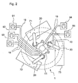
- Fig. 2 a schematic plan view of parts of a rotary device 1 is shown.
- This embodiment of the rotary device has three co-rotating first pumping devices 71, 72, 73, which are connected to the annular distributor 13. Roots pumps are preferably used for the first pumping devices, which are characterized by a high pumping speed at low pressures. On the other hand, such pumps have only a low compressibility, so that in order to achieve low final pressures after completion of evacuation in general precursors are necessary. These are, as already explained above, provided by second, fixed pumping devices, which are connected via a rotary feeder 11 to the pumping devices 71, 72 and 73.
- the in Fig. 2 illustrated embodiment of the rotary device 1 a total of five such fixed pumping devices 91 to 95 on.
- the pumping devices 91 to 95 need not all be of the same type. These may differ in terms of their suction power and the optimum pressure range.
- 91 to 95 rotary vane pumps are used for the pumping devices, which have high suction powers in the rough vacuum range.
- a vacuum diagram is shown for one embodiment of a multi-stage vacuum circuit of a rotary device according to the invention.
- the evacuation is performed in four or five steps.
- the process gas is also pumped out after the evacuation.
- the together with the pumping of the process gas a total of six individual evacuation phases are assigned to angular ranges or sectors 41 to 46, through which the individual Treatment stations 51, 52, ..., 5N move on the conveyor carousel 3 by the rotation of the carousel.
- a treatment station is connected to a single pumping device or to multi-stage pumping devices.
- each of the pumping devices is connected to only one treatment station.
- the connection of the treatment station to a pumping device is then disconnected again.
- the connection and disconnection can also be done by means of a distribution device comprising control valves and a ring manifold.
- the pressures can be measured and checked with suitable pressure measuring tubes 30, for example Pirani measuring tubes.
- the processing station After feeding the workpieces in a loading area, which is associated with a sector 40, the processing station is connected during the passage through the sector 41 with a stationary second pumping device 91, which pumps the coating area of the treatment station to a pressure of ⁇ 200 mbar. If there is a treatment station in the subsequent sector 42, a connection is made to another fixed pumping device 92, which is optimized for a lower pressure range. During the passage through this sector, the pumping device 92 pumps the coating area of the treatment station to a pressure of ⁇ 80 mbar.
- first pumping devices 71, 72 and, in the event of evacuation in five stages co-rotating first pumping devices 71, 72 and, in the event of evacuation in five stages, also an optional further first pumping device 73 used, so that short leads used with large cross-section and difficulties in sealing the rotary feeder can be avoided.
- the treatment stations are pumped to less than or equal to 1.5 mbar, less than or equal to 0.1 mbar, or less than or equal to 0.01 mbar in the event of evacuation in five steps, so that the pressure in each of the evacuation phases is lowered by about one order of magnitude.
- the time between the loading of two treatment stations is very short.
- the pumping times can be kept correspondingly short.
- the finely subdivided gradation of the evacuation process is of great advantage, since the pumps required for this purpose can be kept relatively small.
- first pumping means 71, 72 and 73 second, stationary pumping devices 93, 94 and 95 preceded as a precursor, so that the pump is in two stages to reduce or avoid large compression ratios via individual pumps.
- the fixed second pumping devices 91 to 94 are each designed as rotary vane pumps, which are well suited for pumping against atmospheric pressure.
- all co-rotating first pumping devices 71 to 74 include Roots pumps to provide high suction capacities at low pressures.
- the pumping devices 72 and 74 are additionally designed in two stages and each comprise Roots pumps 721, 722, or 741, 742.
- the coating chamber passes through an angular region 46 associated with the coating.
- process gas is introduced into the coating area and supplied to microwaves, thereby igniting a plasma and coating the workpiece located in the treatment station.
- the coating system is connected to the two-stage pump device 74, which is also connected to a second fixed pumping device like the other first pumping devices.
- a second fixed pumping device like the other first pumping devices.
- the precursor or the fixed second pumping device 96 has a Roots pump.
- the treatment station enters a removal region assigned to the sector 47, where the coated workpiece is taken out and removed by means of a suitable transport device.
- FIGS. 4A and 4B a vacuum scheme of a further embodiment of the invention is shown at two different times, in which these figures for simplicity only the vacuum scheme for the evacuation of the coating stations is shown.
- a plurality of equivalent pumping means are used for individual evacuation phases in order to further increase the pumping capacity.
- the co-rotating first pumping devices 71, 72 and 73 are made equivalent in this embodiment.
- the fixed second Pumping devices 91 and 92 are equivalent and work accordingly at the same pressure with the same pump power.
- the evacuation of the treatment stations 51, 52,..., 5N takes place according to this embodiment of the invention during a first evacuation phase associated with the sector 41 with the equivalent pumping devices 91, 92 and during a second evacuation phase associated with the sector 42 equivalent co-rotating first pumping devices 71, 72, 73rd
- one of the equivalent pumping devices 91, 92, or 71, 72, 73 is in each case connected to at least one treatment station for the duration of the respective evacuation phase associated with sectors 41, or 42.
- a ring manifold 13 and valves 15 may include.
- the treatment stations are each connected on entry into one of the sectors 41, 42 with one of the equivalent pumping devices 91, 92, or 71-73 for the duration of the respective evacuation phase, ie for the duration of the passage of the sectors or circle segments 41, 42.
- the treatment station 52 with the pumping device 91 the treatment station 53 with the pumping device 92, the treatment station 54 with the pumping device 71, the treatment station 55 with the pumping device 72 and the treatment station 56 connected to the pumping device 73.
- the conveyor carousel 3 has rotated further, so that the treatment station 51 has entered the angular range 41.
- the treatment station 53 has completed the evacuation phase associated with the angle region 41 and has entered the subsequent sector 42 associated with a further evacuation phase, where the treatment station 53 has been connected to the co-rotating pump device 73.
- the pumping device 92 previously connected to this treatment station 53 was disconnected from this station upon completion of the evacuation phase associated with the sector 41 and then connected to the treatment station 51 newly entered the sector 41.
- the connecting and disconnecting of the pumping devices 71 - 73 takes place during passage through the sector 42, or at the beginning and end of the evacuation phase associated with this sector, wherein the connecting of the pumping devices 91 and 92, or 71, 72 and 73 for the duration the respective evacuation phase is cyclic, or is continued cyclically.
- groups of at least two treatment stations can each be connected to a pumping device instead of individual treatment stations, which are then each evacuated in groups.
Landscapes
- Chemical & Material Sciences (AREA)
- Engineering & Computer Science (AREA)
- Organic Chemistry (AREA)
- Mechanical Engineering (AREA)
- General Chemical & Material Sciences (AREA)
- Chemical Kinetics & Catalysis (AREA)
- Materials Engineering (AREA)
- Metallurgy (AREA)
- Physics & Mathematics (AREA)
- Plasma & Fusion (AREA)
- Health & Medical Sciences (AREA)
- Manufacturing & Machinery (AREA)
- Medicinal Chemistry (AREA)
- Polymers & Plastics (AREA)
- Analytical Chemistry (AREA)
- Inorganic Chemistry (AREA)
- Life Sciences & Earth Sciences (AREA)
- Geochemistry & Mineralogy (AREA)
- Chemical Vapour Deposition (AREA)
- Compressors, Vaccum Pumps And Other Relevant Systems (AREA)
Applications Claiming Priority (13)
| Application Number | Priority Date | Filing Date | Title |
|---|---|---|---|
| DE10223288 | 2002-05-24 | ||
| DE10223288 | 2002-05-24 | ||
| DE10224395 | 2002-06-01 | ||
| DE10224395A DE10224395A1 (de) | 2002-05-24 | 2002-06-01 | Verfahren und Vorrichtung zur Plasmabehandlung von Werkstücken |
| DE10225607 | 2002-06-07 | ||
| DE10225607A DE10225607A1 (de) | 2002-05-24 | 2002-06-07 | Verfahren und Vorrichtung zur Plasmabehandlung von Werkstücken |
| DE10225985A DE10225985A1 (de) | 2002-05-24 | 2002-06-11 | Verfahren und Vorrichtung zur Plasmabehandlung von Werkstücken |
| DE10225985 | 2002-06-11 | ||
| DE2002153512 DE10253512A1 (de) | 2002-11-16 | 2002-11-16 | Rundläufermaschine für CVD-Beschichtungen |
| DE10253512 | 2002-11-16 | ||
| DE10253513 | 2002-11-16 | ||
| DE2002153513 DE10253513B4 (de) | 2002-11-16 | 2002-11-16 | Mehrplatz-Beschichtungsvorrichtung und Verfahren zur Plasmabeschichtung |
| PCT/EP2003/005499 WO2003100129A1 (de) | 2002-05-24 | 2003-05-26 | Rundläufermaschine für cvd-beschichtungen |
Publications (2)
| Publication Number | Publication Date |
|---|---|
| EP1507895A1 EP1507895A1 (de) | 2005-02-23 |
| EP1507895B1 true EP1507895B1 (de) | 2010-07-21 |
Family
ID=29587928
Family Applications (1)
| Application Number | Title | Priority Date | Filing Date |
|---|---|---|---|
| EP03755134A Expired - Lifetime EP1507895B1 (de) | 2002-05-24 | 2003-05-26 | Rundläufermaschine für cvd-beschichtungen |
Country Status (6)
| Country | Link |
|---|---|
| US (1) | US20050229850A1 (https=) |
| EP (1) | EP1507895B1 (https=) |
| JP (1) | JP4386832B2 (https=) |
| CN (1) | CN100434566C (https=) |
| AU (1) | AU2003242577A1 (https=) |
| WO (1) | WO2003100129A1 (https=) |
Cited By (7)
| Publication number | Priority date | Publication date | Assignee | Title |
|---|---|---|---|---|
| US9272095B2 (en) | 2011-04-01 | 2016-03-01 | Sio2 Medical Products, Inc. | Vessels, contact surfaces, and coating and inspection apparatus and methods |
| US9458536B2 (en) | 2009-07-02 | 2016-10-04 | Sio2 Medical Products, Inc. | PECVD coating methods for capped syringes, cartridges and other articles |
| US9545360B2 (en) | 2009-05-13 | 2017-01-17 | Sio2 Medical Products, Inc. | Saccharide protective coating for pharmaceutical package |
| US9554968B2 (en) | 2013-03-11 | 2017-01-31 | Sio2 Medical Products, Inc. | Trilayer coated pharmaceutical packaging |
| US9572526B2 (en) | 2009-05-13 | 2017-02-21 | Sio2 Medical Products, Inc. | Apparatus and method for transporting a vessel to and from a PECVD processing station |
| US10189603B2 (en) | 2011-11-11 | 2019-01-29 | Sio2 Medical Products, Inc. | Passivation, pH protective or lubricity coating for pharmaceutical package, coating process and apparatus |
| US10201660B2 (en) | 2012-11-30 | 2019-02-12 | Sio2 Medical Products, Inc. | Controlling the uniformity of PECVD deposition on medical syringes, cartridges, and the like |
Families Citing this family (18)
| Publication number | Priority date | Publication date | Assignee | Title |
|---|---|---|---|---|
| DE102004017241B4 (de) | 2004-04-05 | 2012-09-27 | Schott Ag | Verbundmaterial und Verfahren zu seiner Herstellung |
| SI21840A (sl) * | 2004-08-31 | 2006-02-28 | Jozef Bonifarti | Montazna linija - karusel |
| GB0713821D0 (en) * | 2007-07-17 | 2007-08-29 | P2I Ltd | A plasma deposition apparatus |
| CN101688302A (zh) * | 2008-05-30 | 2010-03-31 | 东洋制罐株式会社 | 蒸镀装置 |
| US7985188B2 (en) | 2009-05-13 | 2011-07-26 | Cv Holdings Llc | Vessel, coating, inspection and processing apparatus |
| US11624115B2 (en) | 2010-05-12 | 2023-04-11 | Sio2 Medical Products, Inc. | Syringe with PECVD lubrication |
| US9878101B2 (en) | 2010-11-12 | 2018-01-30 | Sio2 Medical Products, Inc. | Cyclic olefin polymer vessels and vessel coating methods |
| US11116695B2 (en) | 2011-11-11 | 2021-09-14 | Sio2 Medical Products, Inc. | Blood sample collection tube |
| US20150297800A1 (en) | 2012-07-03 | 2015-10-22 | Sio2 Medical Products, Inc. | SiOx BARRIER FOR PHARMACEUTICAL PACKAGE AND COATING PROCESS |
| CA2890066C (en) | 2012-11-01 | 2021-11-09 | Sio2 Medical Products, Inc. | Coating inspection method |
| US9903782B2 (en) | 2012-11-16 | 2018-02-27 | Sio2 Medical Products, Inc. | Method and apparatus for detecting rapid barrier coating integrity characteristics |
| US9764093B2 (en) | 2012-11-30 | 2017-09-19 | Sio2 Medical Products, Inc. | Controlling the uniformity of PECVD deposition |
| US9662450B2 (en) | 2013-03-01 | 2017-05-30 | Sio2 Medical Products, Inc. | Plasma or CVD pre-treatment for lubricated pharmaceutical package, coating process and apparatus |
| US9937099B2 (en) | 2013-03-11 | 2018-04-10 | Sio2 Medical Products, Inc. | Trilayer coated pharmaceutical packaging with low oxygen transmission rate |
| US20160017490A1 (en) | 2013-03-15 | 2016-01-21 | Sio2 Medical Products, Inc. | Coating method |
| WO2015148471A1 (en) | 2014-03-28 | 2015-10-01 | Sio2 Medical Products, Inc. | Antistatic coatings for plastic vessels |
| EP3337915B1 (en) | 2015-08-18 | 2021-11-03 | SiO2 Medical Products, Inc. | Pharmaceutical and other packaging with low oxygen transmission rate |
| CN110002766B (zh) * | 2019-04-24 | 2023-06-23 | 苏州伯宇光电科技有限公司 | 玻璃电致变色膜化学浴镀膜装置 |
Citations (2)
| Publication number | Priority date | Publication date | Assignee | Title |
|---|---|---|---|---|
| FR2791598A1 (fr) * | 1999-03-30 | 2000-10-06 | Sidel Sa | Machine a carrousel pour le traitement de corps creux comportant un circuit de distribution de pression perfectionne et distributeur pour une telle machine |
| JP2000294548A (ja) * | 1999-04-02 | 2000-10-20 | Canon Inc | 誘電体窓を用いたマイクロ波プラズマ処理装置 |
Family Cites Families (4)
| Publication number | Priority date | Publication date | Assignee | Title |
|---|---|---|---|---|
| GB547249A (en) * | 1940-02-14 | 1942-08-20 | British Thomson Houston Co Ltd | Improvements in apparatus for depositing reflecting metallic coatings on base members or bodies |
| US2730987A (en) * | 1954-03-25 | 1956-01-17 | James L Entwistle Company | Apparatus for automatically vacuum coating of interior of glass tubes with metal |
| EP1019944A1 (en) * | 1997-09-30 | 2000-07-19 | Tetra Laval Holdings & Finance S.A. | Method and apparatus for treating the inside surface of plastic bottles in a plasma enhanced process |
| DE19916478A1 (de) * | 1999-04-13 | 2000-10-19 | Ruediger Haaga Gmbh | Verfahren zum Evakuieren eines Plasmasterilisations-Reaktors |
-
2003
- 2003-05-26 CN CNB03811898XA patent/CN100434566C/zh not_active Expired - Lifetime
- 2003-05-26 JP JP2004507566A patent/JP4386832B2/ja not_active Expired - Lifetime
- 2003-05-26 AU AU2003242577A patent/AU2003242577A1/en not_active Abandoned
- 2003-05-26 US US10/514,880 patent/US20050229850A1/en not_active Abandoned
- 2003-05-26 WO PCT/EP2003/005499 patent/WO2003100129A1/de not_active Ceased
- 2003-05-26 EP EP03755134A patent/EP1507895B1/de not_active Expired - Lifetime
Patent Citations (2)
| Publication number | Priority date | Publication date | Assignee | Title |
|---|---|---|---|---|
| FR2791598A1 (fr) * | 1999-03-30 | 2000-10-06 | Sidel Sa | Machine a carrousel pour le traitement de corps creux comportant un circuit de distribution de pression perfectionne et distributeur pour une telle machine |
| JP2000294548A (ja) * | 1999-04-02 | 2000-10-20 | Canon Inc | 誘電体窓を用いたマイクロ波プラズマ処理装置 |
Non-Patent Citations (1)
| Title |
|---|
| DATABASE WPI Week 200111, Derwent World Patents Index; Class L03, AN 2001-095118 * |
Cited By (8)
| Publication number | Priority date | Publication date | Assignee | Title |
|---|---|---|---|---|
| US9545360B2 (en) | 2009-05-13 | 2017-01-17 | Sio2 Medical Products, Inc. | Saccharide protective coating for pharmaceutical package |
| US9572526B2 (en) | 2009-05-13 | 2017-02-21 | Sio2 Medical Products, Inc. | Apparatus and method for transporting a vessel to and from a PECVD processing station |
| US9458536B2 (en) | 2009-07-02 | 2016-10-04 | Sio2 Medical Products, Inc. | PECVD coating methods for capped syringes, cartridges and other articles |
| US9272095B2 (en) | 2011-04-01 | 2016-03-01 | Sio2 Medical Products, Inc. | Vessels, contact surfaces, and coating and inspection apparatus and methods |
| US10189603B2 (en) | 2011-11-11 | 2019-01-29 | Sio2 Medical Products, Inc. | Passivation, pH protective or lubricity coating for pharmaceutical package, coating process and apparatus |
| US10201660B2 (en) | 2012-11-30 | 2019-02-12 | Sio2 Medical Products, Inc. | Controlling the uniformity of PECVD deposition on medical syringes, cartridges, and the like |
| US9554968B2 (en) | 2013-03-11 | 2017-01-31 | Sio2 Medical Products, Inc. | Trilayer coated pharmaceutical packaging |
| US10016338B2 (en) | 2013-03-11 | 2018-07-10 | Sio2 Medical Products, Inc. | Trilayer coated pharmaceutical packaging |
Also Published As
| Publication number | Publication date |
|---|---|
| AU2003242577A1 (en) | 2003-12-12 |
| WO2003100129A1 (de) | 2003-12-04 |
| JP2005526915A (ja) | 2005-09-08 |
| CN100434566C (zh) | 2008-11-19 |
| JP4386832B2 (ja) | 2009-12-16 |
| EP1507895A1 (de) | 2005-02-23 |
| US20050229850A1 (en) | 2005-10-20 |
| CN1656250A (zh) | 2005-08-17 |
Similar Documents
| Publication | Publication Date | Title |
|---|---|---|
| EP1507895B1 (de) | Rundläufermaschine für cvd-beschichtungen | |
| EP1507887B1 (de) | Mehrplatz-beschichtungsvorrichtung und verfahren zur plasmabeschichtung | |
| EP0307539B1 (de) | Verfahren und Vorrichtung zum Beschichten von Substraten | |
| EP1507890B1 (de) | Verfahren und vorrichtung zur plasmabehandlung von werkstücken | |
| EP1507893B1 (de) | Verfahren und vorrichtung zur plasmabehandlung von werkstücken | |
| EP1507894B1 (de) | Beschichtungsvorrichtung mit transporteinrichtung | |
| EP3433395B1 (de) | Verfahren und vorrichtung zur plasmabehandlung von behältern | |
| DE102004028369B4 (de) | Verfahren und Vorrichtung zum Behandeln von Substraten in einer Rundläuferanlage | |
| EP1537253A1 (de) | Vorrichtung und verfahren zur behandlung von werkst cken | |
| DE10225985A1 (de) | Verfahren und Vorrichtung zur Plasmabehandlung von Werkstücken | |
| DE102008026001B4 (de) | Verfahren und Vorrichtung zur Erzeugung und Bearbeitung von Schichten auf Substraten unter definierter Prozessatmosphäre und Heizelement | |
| DE10253512A1 (de) | Rundläufermaschine für CVD-Beschichtungen | |
| EP4640418A2 (de) | Anlage, verfahren und träger zur beschichtung von brillengläsern | |
| EP2581096A1 (de) | Vorrichtung und Verfahren zum Sterilisieren von Behältnissen mit in die Behältnisse eingeführter Ladungsträgerquelle | |
| EP4059039B1 (de) | Vorrichtung und verfahren zur plasmabehandlung von behältern | |
| DE10236683B4 (de) | Vorrichtung zur Plasmabehandlung von Hohlkörpern, insbesondere Flaschen | |
| WO2003100124A1 (de) | Verfahren und vorrichtung zur plasmabehandlung von werkstücken | |
| EP2964274B1 (de) | Verfahren und vorrichtung zur plasmabehandlung von hohlkörpern | |
| EP1884576A2 (de) | Vorrichtung zur Plasmabeschichtung von länglichen, zylindrischen Bauteilen | |
| DE10314067A1 (de) | Beschichtungsvorrichtung mit Transporteinrichtung | |
| WO2009121324A1 (de) | Vorrichtung zur plasmabehandlung von werkstücken | |
| DE102005024180A1 (de) | Vakuumbeschichtungsanlage und Transferkammer dafür | |
| DE10253513B4 (de) | Mehrplatz-Beschichtungsvorrichtung und Verfahren zur Plasmabeschichtung | |
| WO2013131508A1 (de) | Vorrichtung und verfahren zur plasmabeschichtung von länglichen zylindrischen bauteilen | |
| EP4417730A1 (de) | Vorrichtung und verfahren zur versorgung einer anlage zur beschichtung von werkstücken mit für den beschichtungsprozess benötigten prozessgasen |
Legal Events
| Date | Code | Title | Description |
|---|---|---|---|
| PUAI | Public reference made under article 153(3) epc to a published international application that has entered the european phase |
Free format text: ORIGINAL CODE: 0009012 |
|
| 17P | Request for examination filed |
Effective date: 20041111 |
|
| AK | Designated contracting states |
Kind code of ref document: A1 Designated state(s): AT BE BG CH CY CZ DE DK EE ES FI FR GB GR HU IE IT LI LU MC NL PT RO SE SI SK TR |
|
| AX | Request for extension of the european patent |
Extension state: AL LT LV MK |
|
| RAP1 | Party data changed (applicant data changed or rights of an application transferred) |
Owner name: SCHOTT AG |
|
| RIN1 | Information on inventor provided before grant (corrected) |
Inventor name: BEHLE, STEPHAN Inventor name: LUETTRINGHAUS-HENKEL, ANDREAS Inventor name: BICKER, MATTHIAS Inventor name: KLEIN, JUERGEN Inventor name: ARNOLD, GREGOR |
|
| DAX | Request for extension of the european patent (deleted) | ||
| 17Q | First examination report despatched |
Effective date: 20070212 |
|
| GRAP | Despatch of communication of intention to grant a patent |
Free format text: ORIGINAL CODE: EPIDOSNIGR1 |
|
| GRAS | Grant fee paid |
Free format text: ORIGINAL CODE: EPIDOSNIGR3 |
|
| GRAA | (expected) grant |
Free format text: ORIGINAL CODE: 0009210 |
|
| AK | Designated contracting states |
Kind code of ref document: B1 Designated state(s): AT BE BG CH CY CZ DE DK EE ES FI FR GB GR HU IE IT LI LU MC NL PT RO SE SI SK TR |
|
| REG | Reference to a national code |
Ref country code: GB Ref legal event code: FG4D Free format text: NOT ENGLISH |
|
| REG | Reference to a national code |
Ref country code: CH Ref legal event code: EP |
|
| REG | Reference to a national code |
Ref country code: IE Ref legal event code: FG4D |
|
| REF | Corresponds to: |
Ref document number: 50312906 Country of ref document: DE Date of ref document: 20100902 Kind code of ref document: P |
|
| REG | Reference to a national code |
Ref country code: NL Ref legal event code: VDEP Effective date: 20100721 |
|
| PG25 | Lapsed in a contracting state [announced via postgrant information from national office to epo] |
Ref country code: NL Free format text: LAPSE BECAUSE OF FAILURE TO SUBMIT A TRANSLATION OF THE DESCRIPTION OR TO PAY THE FEE WITHIN THE PRESCRIBED TIME-LIMIT Effective date: 20100721 Ref country code: FI Free format text: LAPSE BECAUSE OF FAILURE TO SUBMIT A TRANSLATION OF THE DESCRIPTION OR TO PAY THE FEE WITHIN THE PRESCRIBED TIME-LIMIT Effective date: 20100721 |
|
| REG | Reference to a national code |
Ref country code: IE Ref legal event code: FD4D |
|
| PG25 | Lapsed in a contracting state [announced via postgrant information from national office to epo] |
Ref country code: SI Free format text: LAPSE BECAUSE OF FAILURE TO SUBMIT A TRANSLATION OF THE DESCRIPTION OR TO PAY THE FEE WITHIN THE PRESCRIBED TIME-LIMIT Effective date: 20100721 Ref country code: PT Free format text: LAPSE BECAUSE OF FAILURE TO SUBMIT A TRANSLATION OF THE DESCRIPTION OR TO PAY THE FEE WITHIN THE PRESCRIBED TIME-LIMIT Effective date: 20101122 Ref country code: CY Free format text: LAPSE BECAUSE OF FAILURE TO SUBMIT A TRANSLATION OF THE DESCRIPTION OR TO PAY THE FEE WITHIN THE PRESCRIBED TIME-LIMIT Effective date: 20100721 Ref country code: BG Free format text: LAPSE BECAUSE OF FAILURE TO SUBMIT A TRANSLATION OF THE DESCRIPTION OR TO PAY THE FEE WITHIN THE PRESCRIBED TIME-LIMIT Effective date: 20101021 |
|
| PG25 | Lapsed in a contracting state [announced via postgrant information from national office to epo] |
Ref country code: GR Free format text: LAPSE BECAUSE OF FAILURE TO SUBMIT A TRANSLATION OF THE DESCRIPTION OR TO PAY THE FEE WITHIN THE PRESCRIBED TIME-LIMIT Effective date: 20101022 Ref country code: SE Free format text: LAPSE BECAUSE OF FAILURE TO SUBMIT A TRANSLATION OF THE DESCRIPTION OR TO PAY THE FEE WITHIN THE PRESCRIBED TIME-LIMIT Effective date: 20100721 |
|
| PG25 | Lapsed in a contracting state [announced via postgrant information from national office to epo] |
Ref country code: IE Free format text: LAPSE BECAUSE OF FAILURE TO SUBMIT A TRANSLATION OF THE DESCRIPTION OR TO PAY THE FEE WITHIN THE PRESCRIBED TIME-LIMIT Effective date: 20100721 Ref country code: DK Free format text: LAPSE BECAUSE OF FAILURE TO SUBMIT A TRANSLATION OF THE DESCRIPTION OR TO PAY THE FEE WITHIN THE PRESCRIBED TIME-LIMIT Effective date: 20100721 |
|
| PLBE | No opposition filed within time limit |
Free format text: ORIGINAL CODE: 0009261 |
|
| STAA | Information on the status of an ep patent application or granted ep patent |
Free format text: STATUS: NO OPPOSITION FILED WITHIN TIME LIMIT |
|
| PG25 | Lapsed in a contracting state [announced via postgrant information from national office to epo] |
Ref country code: IT Free format text: LAPSE BECAUSE OF FAILURE TO SUBMIT A TRANSLATION OF THE DESCRIPTION OR TO PAY THE FEE WITHIN THE PRESCRIBED TIME-LIMIT Effective date: 20100721 Ref country code: CZ Free format text: LAPSE BECAUSE OF FAILURE TO SUBMIT A TRANSLATION OF THE DESCRIPTION OR TO PAY THE FEE WITHIN THE PRESCRIBED TIME-LIMIT Effective date: 20100721 Ref country code: SK Free format text: LAPSE BECAUSE OF FAILURE TO SUBMIT A TRANSLATION OF THE DESCRIPTION OR TO PAY THE FEE WITHIN THE PRESCRIBED TIME-LIMIT Effective date: 20100721 Ref country code: RO Free format text: LAPSE BECAUSE OF FAILURE TO SUBMIT A TRANSLATION OF THE DESCRIPTION OR TO PAY THE FEE WITHIN THE PRESCRIBED TIME-LIMIT Effective date: 20100721 Ref country code: EE Free format text: LAPSE BECAUSE OF FAILURE TO SUBMIT A TRANSLATION OF THE DESCRIPTION OR TO PAY THE FEE WITHIN THE PRESCRIBED TIME-LIMIT Effective date: 20100721 |
|
| 26N | No opposition filed |
Effective date: 20110426 |
|
| PG25 | Lapsed in a contracting state [announced via postgrant information from national office to epo] |
Ref country code: ES Free format text: LAPSE BECAUSE OF FAILURE TO SUBMIT A TRANSLATION OF THE DESCRIPTION OR TO PAY THE FEE WITHIN THE PRESCRIBED TIME-LIMIT Effective date: 20101101 |
|
| REG | Reference to a national code |
Ref country code: DE Ref legal event code: R097 Ref document number: 50312906 Country of ref document: DE Effective date: 20110426 |
|
| BERE | Be: lapsed |
Owner name: SCHOTT A.G. Effective date: 20110531 |
|
| PG25 | Lapsed in a contracting state [announced via postgrant information from national office to epo] |
Ref country code: MC Free format text: LAPSE BECAUSE OF NON-PAYMENT OF DUE FEES Effective date: 20110531 |
|
| REG | Reference to a national code |
Ref country code: CH Ref legal event code: PL |
|
| GBPC | Gb: european patent ceased through non-payment of renewal fee |
Effective date: 20110526 |
|
| PG25 | Lapsed in a contracting state [announced via postgrant information from national office to epo] |
Ref country code: LI Free format text: LAPSE BECAUSE OF NON-PAYMENT OF DUE FEES Effective date: 20110531 Ref country code: CH Free format text: LAPSE BECAUSE OF NON-PAYMENT OF DUE FEES Effective date: 20110531 |
|
| REG | Reference to a national code |
Ref country code: FR Ref legal event code: ST Effective date: 20120131 |
|
| REG | Reference to a national code |
Ref country code: DE Ref legal event code: R119 Ref document number: 50312906 Country of ref document: DE Effective date: 20111201 |
|
| PG25 | Lapsed in a contracting state [announced via postgrant information from national office to epo] |
Ref country code: BE Free format text: LAPSE BECAUSE OF NON-PAYMENT OF DUE FEES Effective date: 20110531 |
|
| PG25 | Lapsed in a contracting state [announced via postgrant information from national office to epo] |
Ref country code: FR Free format text: LAPSE BECAUSE OF NON-PAYMENT OF DUE FEES Effective date: 20110531 |
|
| PG25 | Lapsed in a contracting state [announced via postgrant information from national office to epo] |
Ref country code: GB Free format text: LAPSE BECAUSE OF NON-PAYMENT OF DUE FEES Effective date: 20110526 |
|
| REG | Reference to a national code |
Ref country code: AT Ref legal event code: MM01 Ref document number: 474943 Country of ref document: AT Kind code of ref document: T Effective date: 20110526 |
|
| PG25 | Lapsed in a contracting state [announced via postgrant information from national office to epo] |
Ref country code: AT Free format text: LAPSE BECAUSE OF NON-PAYMENT OF DUE FEES Effective date: 20110526 |
|
| PG25 | Lapsed in a contracting state [announced via postgrant information from national office to epo] |
Ref country code: LU Free format text: LAPSE BECAUSE OF NON-PAYMENT OF DUE FEES Effective date: 20110526 |
|
| PG25 | Lapsed in a contracting state [announced via postgrant information from national office to epo] |
Ref country code: DE Free format text: LAPSE BECAUSE OF NON-PAYMENT OF DUE FEES Effective date: 20111201 |
|
| PG25 | Lapsed in a contracting state [announced via postgrant information from national office to epo] |
Ref country code: TR Free format text: LAPSE BECAUSE OF FAILURE TO SUBMIT A TRANSLATION OF THE DESCRIPTION OR TO PAY THE FEE WITHIN THE PRESCRIBED TIME-LIMIT Effective date: 20100721 |
|
| PG25 | Lapsed in a contracting state [announced via postgrant information from national office to epo] |
Ref country code: HU Free format text: LAPSE BECAUSE OF FAILURE TO SUBMIT A TRANSLATION OF THE DESCRIPTION OR TO PAY THE FEE WITHIN THE PRESCRIBED TIME-LIMIT Effective date: 20100721 |