EP1507695B1 - Système de charnière et du support pour un plateau intermédiaire d'une remorque - Google Patents
Système de charnière et du support pour un plateau intermédiaire d'une remorque Download PDFInfo
- Publication number
- EP1507695B1 EP1507695B1 EP03755062A EP03755062A EP1507695B1 EP 1507695 B1 EP1507695 B1 EP 1507695B1 EP 03755062 A EP03755062 A EP 03755062A EP 03755062 A EP03755062 A EP 03755062A EP 1507695 B1 EP1507695 B1 EP 1507695B1
- Authority
- EP
- European Patent Office
- Prior art keywords
- deck panel
- deck
- panel
- support
- Prior art date
- Legal status (The legal status is an assumption and is not a legal conclusion. Google has not performed a legal analysis and makes no representation as to the accuracy of the status listed.)
- Expired - Lifetime
Links
- 230000000717 retained effect Effects 0.000 claims abstract description 13
- 230000002093 peripheral effect Effects 0.000 claims 1
- 239000007858 starting material Substances 0.000 description 13
- 238000003780 insertion Methods 0.000 description 8
- 230000037431 insertion Effects 0.000 description 8
- 230000013011 mating Effects 0.000 description 7
- 230000006378 damage Effects 0.000 description 4
- 230000000284 resting effect Effects 0.000 description 4
- 230000008901 benefit Effects 0.000 description 3
- 239000000463 material Substances 0.000 description 3
- 238000000034 method Methods 0.000 description 3
- 229910052782 aluminium Inorganic materials 0.000 description 2
- XAGFODPZIPBFFR-UHFFFAOYSA-N aluminium Chemical compound [Al] XAGFODPZIPBFFR-UHFFFAOYSA-N 0.000 description 2
- 230000000670 limiting effect Effects 0.000 description 2
- 238000012986 modification Methods 0.000 description 2
- 230000004048 modification Effects 0.000 description 2
- 230000036961 partial effect Effects 0.000 description 2
- 239000004033 plastic Substances 0.000 description 2
- 238000003466 welding Methods 0.000 description 2
- 241001288024 Lagascea mollis Species 0.000 description 1
- 239000004677 Nylon Substances 0.000 description 1
- 208000027418 Wounds and injury Diseases 0.000 description 1
- 230000002411 adverse Effects 0.000 description 1
- 238000005452 bending Methods 0.000 description 1
- 239000002131 composite material Substances 0.000 description 1
- 230000006835 compression Effects 0.000 description 1
- 238000007906 compression Methods 0.000 description 1
- 238000010276 construction Methods 0.000 description 1
- 238000001125 extrusion Methods 0.000 description 1
- 239000011521 glass Substances 0.000 description 1
- 208000014674 injury Diseases 0.000 description 1
- 230000009191 jumping Effects 0.000 description 1
- 229910052751 metal Inorganic materials 0.000 description 1
- 239000007769 metal material Substances 0.000 description 1
- 239000002991 molded plastic Substances 0.000 description 1
- 229920001778 nylon Polymers 0.000 description 1
- 230000003014 reinforcing effect Effects 0.000 description 1
- 238000010008 shearing Methods 0.000 description 1
- 239000000725 suspension Substances 0.000 description 1
Images


Classifications
-
- E—FIXED CONSTRUCTIONS
- E05—LOCKS; KEYS; WINDOW OR DOOR FITTINGS; SAFES
- E05D—HINGES OR SUSPENSION DEVICES FOR DOORS, WINDOWS OR WINGS
- E05D7/00—Hinges or pivots of special construction
- E05D7/10—Hinges or pivots of special construction to allow easy separation or connection of the parts at the hinge axis
- E05D7/1061—Hinges or pivots of special construction to allow easy separation or connection of the parts at the hinge axis in a radial direction
- E05D7/1066—Hinges or pivots of special construction to allow easy separation or connection of the parts at the hinge axis in a radial direction requiring a specific angular position
-
- B—PERFORMING OPERATIONS; TRANSPORTING
- B60—VEHICLES IN GENERAL
- B60P—VEHICLES ADAPTED FOR LOAD TRANSPORTATION OR TO TRANSPORT, TO CARRY, OR TO COMPRISE SPECIAL LOADS OR OBJECTS
- B60P1/00—Vehicles predominantly for transporting loads and modified to facilitate loading, consolidating the load, or unloading
-
- B—PERFORMING OPERATIONS; TRANSPORTING
- B61—RAILWAYS
- B61D—BODY DETAILS OR KINDS OF RAILWAY VEHICLES
- B61D3/00—Wagons or vans
- B61D3/02—Wagons or vans with multiple deck arrangements
-
- B—PERFORMING OPERATIONS; TRANSPORTING
- B61—RAILWAYS
- B61D—BODY DETAILS OR KINDS OF RAILWAY VEHICLES
- B61D3/00—Wagons or vans
- B61D3/04—Wagons or vans with movable floors, e.g. rotatable or floors which can be raised or lowered
-
- B—PERFORMING OPERATIONS; TRANSPORTING
- B62—LAND VEHICLES FOR TRAVELLING OTHERWISE THAN ON RAILS
- B62D—MOTOR VEHICLES; TRAILERS
- B62D33/00—Superstructures for load-carrying vehicles
- B62D33/04—Enclosed load compartments ; Frameworks for movable panels, tarpaulins or side curtains
- B62D33/042—Enclosed load compartments ; Frameworks for movable panels, tarpaulins or side curtains divided into compartments
-
- E—FIXED CONSTRUCTIONS
- E05—LOCKS; KEYS; WINDOW OR DOOR FITTINGS; SAFES
- E05D—HINGES OR SUSPENSION DEVICES FOR DOORS, WINDOWS OR WINGS
- E05D1/00—Pinless hinges; Substitutes for hinges
- E05D1/02—Pinless hinges; Substitutes for hinges made of one piece
-
- E—FIXED CONSTRUCTIONS
- E05—LOCKS; KEYS; WINDOW OR DOOR FITTINGS; SAFES
- E05D—HINGES OR SUSPENSION DEVICES FOR DOORS, WINDOWS OR WINGS
- E05D7/00—Hinges or pivots of special construction
- E05D7/10—Hinges or pivots of special construction to allow easy separation or connection of the parts at the hinge axis
- E05D7/1061—Hinges or pivots of special construction to allow easy separation or connection of the parts at the hinge axis in a radial direction
- E05D7/1077—Hinges or pivots of special construction to allow easy separation or connection of the parts at the hinge axis in a radial direction with snap-fitted pins
-
- E—FIXED CONSTRUCTIONS
- E05—LOCKS; KEYS; WINDOW OR DOOR FITTINGS; SAFES
- E05D—HINGES OR SUSPENSION DEVICES FOR DOORS, WINDOWS OR WINGS
- E05D7/00—Hinges or pivots of special construction
- E05D7/10—Hinges or pivots of special construction to allow easy separation or connection of the parts at the hinge axis
- E05D7/1061—Hinges or pivots of special construction to allow easy separation or connection of the parts at the hinge axis in a radial direction
- E05D7/1066—Hinges or pivots of special construction to allow easy separation or connection of the parts at the hinge axis in a radial direction requiring a specific angular position
- E05D7/1072—Hinges or pivots of special construction to allow easy separation or connection of the parts at the hinge axis in a radial direction requiring a specific angular position the pin having a non-circular cross-section
-
- E—FIXED CONSTRUCTIONS
- E05—LOCKS; KEYS; WINDOW OR DOOR FITTINGS; SAFES
- E05Y—INDEXING SCHEME ASSOCIATED WITH SUBCLASSES E05D AND E05F, RELATING TO CONSTRUCTION ELEMENTS, ELECTRIC CONTROL, POWER SUPPLY, POWER SIGNAL OR TRANSMISSION, USER INTERFACES, MOUNTING OR COUPLING, DETAILS, ACCESSORIES, AUXILIARY OPERATIONS NOT OTHERWISE PROVIDED FOR, APPLICATION THEREOF
- E05Y2900/00—Application of doors, windows, wings or fittings thereof
- E05Y2900/50—Application of doors, windows, wings or fittings thereof for vehicles
- E05Y2900/516—Application of doors, windows, wings or fittings thereof for vehicles for trucks or trailers
Definitions
- the invention relates to intermediate deck structures for use in transport vehicles such as trucks and trailer vans, railway cars, freight containers and the like, and more particularly, to a hinge and support system for an interlocking deck for use in such vehicles suitable for loading and transporting parcels.
- a horizontal bed or floor is provided for supporting articles being transported. Articles are placed on this bed, and depending upon the size of the articles, they may be stacked upon each other at two or more levels.
- Some articles are also somewhat difficult to handle due to their weight and configuration. This creates problems for the individuals loading the articles on a bed. Thus, even if articles at a lower level will not be damaged when other articles are stacked thereon, stacking itself may be quite cumbersome and inefficient due to the size and weight of the articles.
- United States Patent No. 3,911,832 to Vandergriff discloses an intermediate deck structure for use in railway cars, truck and trailer vans.
- the deck structure includes a first section pivotally connected at its outer end to the side wall of a vehicle, and adapted to be pivoted between a stored position adjacent the side wall and a horizontal position with its inner end extending inwardly from the side wall.
- a second section of the Vandergriff intermediate deck has a pair of arms extended from its inner end which are pivotally connected to the first section at a point between the inner and outer ends.
- the second section of the intermediate deck is adapted to be stored adjacent the side wall of the vehicle below the first section of the intermediate deck in a position extending downwardly from the outer end of the stored first section.
- the second section is adapted to be pivoted relative to the first section during pivoting of the first section to a horizontal loading position, whereby the second section can also be moved to a horizontal loading position with the outer end of the second section supported by a pair of load brackets engaged with a load rail on the opposite side wall of the vehicle.
- a problem encountered with the intermediate deck structure of Vandergriff is that the individual deck structures do not lock together when the two deck sections are stored against the side wall of the vehicle, and the load bracket on the second section extends downwardly to a position where it can interfere with and damage cargo and boxes sitting on the main floor of the vehicle.
- a further problem with the Vandergriff deck is that the load brackets employed in the intermediate deck structure are subject to jumping out of the wall load track rail slots, causing the load brackets to retract under a load on the deck, and dropping the load onto the cargo positioned underneath the intermediate deck.
- United States Patent No. 5,452,972 to Adams discloses a deck structure for use in supporting cargo at an intermediate level above the floor or bed of a trailer van.
- the Adams intermediate deck includes a first deck section pivotally mounted on a side wall of a trailer van and movable to a horizontal load position, and back up to a vertical stored position against the side wall.
- Adams employs a complex spring slam bolt and release chain system engaged with a height saving angle locking rail to releaseably hold the deck section.
- a second section of the deck is pivotally connected to the first section and it is also movable between a horizontal load position and a vertical stored position against the side wall.
- the second section When the second section is in the vertical stored position it is hanging from the first section and is configured such that it nests in the first deck section to provide a storing intermediate deck structure.
- the second section When the first and second deck sections are in a horizontal load position, the second section has an outer end which is selectively provided with either the spring biased, telescopically mounted load bracket, or a cap style load bracket, that is operatively seated on a load track rail on the trailer van wall opposite to the wall on which the first deck section is hinged.
- the intermediate deck structure of Adams addresses some of the problems of Vandergriff, in doing so it employs complex chain and spring systems that increase the expense of the intermediate deck structure and enhance the risk of injury to the operator of the system. Also, like Vandergriff, Adams fails to address the problem of the lack of structure to lock individual deck structures together.
- United States Patent No. 3,875,871 to Thorton discloses a freight carrier such as a railroad car having sections which, unlike the structures in Vandergriff or Adams, fold from opposite walls toward one another from a stored position to an operational position. In the installed position the sections provide a supplementary cargo level. According to Thorton, in this position the sections have joining means which self-support the load and transmit lading shearing and bending moments between the sections so that additional supports from the floor are not required.
- the deck sections of the Thorton carrier are provided with flanges or blocks for supporting the sections when they are unfolded and for providing a resting space for subsequently lowered sections.
- Thorton also describes permanent support areas positioned at one end of the freight car designed to provide a resting area for the first lowered panels. The patent describes these rest areas as a bracket or ledge mounted on the rear wall of the carrier by suitable fasteners or welding.
- Thorton seemingly overcomes many of the problems of Vandergriff and the complexities of Adams, it requires welding structures or fasteners to the interior portion of the carrier to do so. Moreover, although Thorton provides flanges or blocks for supporting subsequent sections, the panels described in Thorton are vulnerable to sag under heavier loads due to inadequate support. Moreover, the flanges or blocks of Thorton subject the panels to interference with one another and, like Vandergriff and Adams, do not interlock the panels together in the operational position. Another problem encountered with such systems is stress placed on attachment and hinge systems by flexing of trailer side walls, for example while the vehicle is travelling on the road. Furthermore, in some systems a hinge utilized for deploying and stowing an intermediate deck may have to bear the full weight of the items loaded on the intermediate deck.
- EP-A-0247756 discloses a hinge comprising an arcuate female member and a snap in male member, the male member having projections engageable in slots defined in the female member, to limit relative pivoting thereof.
- One aspect of the present invention is a hinge and support system by which a deployable deck panel unit is attached to a side wall of a freight compartment.
- the freight compartment may be in a vehicle, such as a semitrailer, a container of the type used in intermodal shipment of goods, or other compartment or enclosure suitable for transporting items.
- the hinge and support system includes a support member attached to a side wall of the compartment, the support member defining one or more pockets opening generally away from the side wall.
- a hinge member associated with a deck panel includes one or more projections shaped to be inserted into and retained within a mating pocket of the support member until selectively removed from the mating pocket.
- the projections are flexible and are inserted and retained by applying a sufficient force to snap the projections into the pocket.
- the projections can be removed by snapping them out of the pocket.
- the hinge member includes rigid projections that may include a locking plunger and the assembly is snapped into and retained within the mating pocket.
- the rigid projections are shaped to allow insertion and removal only in a particular orientation, but without a snapping action or application of force. As will become apparent from the detailed description below, the shape of the pockets and projections may vary widely so long as they function as described above.
- this aspect of the invention provides a hinge and support system for pivotally mounting a deck panel to a side wall of a freight compartment, comprising: a support member, extending generally horizontally along one of the side walls, defining one or more pockets therein, the one or more pockets each defining an elongate channel positioned along a pivot axis; and a hinge member, associated with a deck panel, defining a flexible projection sized and shaped to be snapped into and retained within the pocket so as to allow pivotal movement of the hinge member with respect to the support member about the pivot axis.
- a support member for a hinge member defines one or two ledges for a deck panel associated with the hinge member.
- One type of ledge is positioned to support the weight of the deck panel when stowed against a side wall of a compartment, and the other type of ledge is positioned to support the weight of the deck panel, and items loaded on it, when deployed away from the side wall.
- the ledges need not be smooth or planar or continuous; they should provide sufficient points of support to receive the deck panel in a stable fashion.
- the invention provides a freight compartment, comprising a compartment having a floor and at least two spaced apart side walls; at least one support member, extending generally horizontally along one of the side walls; and at least one hinge member, associated with a deck panel, engaging the support member so as to allow pivotal movement of the hinge member, along with the associated deck panel, between a generally upright stowed position and a generally horizontal deployed position, about a pivot axis; wherein the deck panel associated with the hinge member at least partially defines a platform in the compartment spaced above the floor when the deck panel is in the deployed position; and wherein the support member defines a first ledge, wherein the first ledge is positioned to engage the deck panel in a deployed configuration so as to substantially isolate the hinge member from weight of the deck panel and items on it.
- the support member optionally and preferably defines a second ledge, wherein the second ledge is positioned to bear weight of the deck panel when stowed generally upright against the side wall so as to substantially isolate the hinge member from the weight
- a hinge member is movably supported by a deck panel so that the hinge member can move relative to the deck panel when the deck panel is deployed, such movement having a component of motion perpendicular to the side wall of the compartment.
- the hinge member moves relative to the deck panel, in most cases preventing the force of the flexing side wall from snapping a hinge member out of the pocket in which it is engaged.
- the invention provides a freight compartment, comprising a compartment having a floor and at least two spaced apart side walls at least one support member, extending generally horizontally along one of the side walls; and at least one hinge member, associated with a deck panel, engaging the support member so as to allow pivotal movement of the hinge member, and the associated deck panel, between a generally upright stowed position and a generally horizontal deployed position; wherein the deck panel associated with the hinge member at least partially defines a platform in the compartment spaced above the floor when the deck panel is in the deployed position; and wherein the hinge member is movably supported by the deck panel so that the hinge member can move relative to the deck panel when the deck panel is deployed, such movement having a component of motion perpendicular to the side wall.
- the hinge member includes at least one block sized to be received in a cavity formed in an end of the deck panel.
- the block can move within the cavity, and is urged into the cavity.
- a plurality of separate blocks and cavities may be provided for a deck panel.
- One of various intermediate deck support systems with which the hinge and support system may be utilized includes at least one pair of deck panels mounted opposite one another on the side walls, the deck panels being capable of movement between an upright or stowed position and a deployed position.
- Each of the respective deck panels have an end pivotably mounted to the side wall and a free end. When the deck panels are in the deployed position they at least partially define a secondary platform of the vehicle freight compartment when the free ends are adjacent to one another in the deployed position.
- the deck support system also includes one or more anchors mounted to each of the side walls of the freight compartment to secure the deck panels to the side walls in the upright position.
- the system includes a support bracket that removably engages the deck panels adjacent the free ends when the deck panels are in the deployed position.
- the support bracket removably engages the deck panels along a side edge of each panel.
- the support bracket interlocks the pair of deployed deck panels and provides a support ledge for other deck panels.
- the bracket has an elongated body, which preferably has a rectangular cross section and defines a longitudinal axis.
- the elongated body has a first side and a second side with a longitudinally extending channel defined in the first side, which is shaped for removable engagement with the pair of deck panels.
- the elongated body also has a longitudinally extending support ledge defined in its second side.
- the longitudinally extending channel of the bracket interlocks the deployed deck panels and the longitudinally extending support ledge is capable of providing support to further pairs of deployed deck panels.
- the longitudinally extending channel slidably engages the deployed deck panels and is capable of linear movement perpendicular to the mating faces of the deployed deck panels.
- This arrangement may further include a stop bracket affixed to one panel limiting the sliding movement of the channel to facilitate optimal positioning of the channel relative to the panels.
- the first side of the elongated body of the bracket is pivotably secured to one of the deck panels of the pair and the longitudinally extending channel pivotably engages the deployed deck panels.
- the deck support system also includes a horizontal starter panel secured at the front of the freight compartment between the side walls and adjacent at least one pair of the deployed deck panels.
- a support bracket is secured to the starter panel to support a pair of deployed deck panels adjacent the starter panel.
- the deck support system of the present invention supports articles more efficiently than prior art systems for transportation purposes.
- the deck support system is lightweight and is of highly efficient design whereby the deck can be economically installed in a vehicle, each individual intermediate deck is adequately supported and can be locked together with other decks, and the system can be efficiently operated by a single user.
- This aspect of the invention provides a hinge structure, comprising a first member defining one or more pockets therein, the one or more pockets each defining an elongate channel positioned along a pivot axis; and a second member defining at least one flexible projection sized and shaped to be snapped into and retained within one of the pockets so as to allow pivotal movement of the first member with respect to the second member about the pivot axis.
- the flexible projection is of a flexibility selected so that one person can force the flexible projection to be snapped into and, pulled out of the pocket.
- each elongate channel may include a part-circular cross section that extends beyond 180 degrees so as to allow the pocket to trap the flexible projection when the flexible projection is forced to flex and snap into the pocket, and the flexible projection may comprise an arcuate finger that lies along a portion of a circle.
- the one or more channels may each define an elongate opening through which the fingers extend, the opening being sufficiently wide to allow the second member to rotate from a generally horizontal position to a generally upright position.
- the second member comprises a rigid projection further comprising a first piece largely circular in cross section mating with a second piece comprising a locking plunger, such that when the two pieces are fully mated, the assembly provides a near complete circular cross section.
- the locking plunger is held in a mated position by a locking screw or spring.
- the effective diameter at a specific orientation is less than the inside diameter of the pocket and the assembly can be inserted into the retaining pocket when positioned at a specific angle relative to the pocket.
- the locking plunger returns to a fully mated position automatically by spring action or by adjusting the locking screw.
- the effective diameter at the specific orientation increases and the hinge assembly can then pivot freely.
- the hinge assembly cannot be removed from the pocket except when positioned at the specific angular position and the locking plunger is partially mated.
- the locking plunger is omitted and the hinge structure comprises a rigid projection that is largely circular in cross section.
- the hinge structure can be inserted and removed from the pocket only at a specific angular position, but without application of any force or adjustment of locking screws.
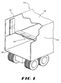
- FIGS. 1-11 illustrate a deck support system, indicated generally at 10 in Figure 1, installed on a truck trailer 12 .
- the truck trailer 12 is enclosed by side walls 14 , a roof 16 and a floor 18 .
- the deck support system of the present invention need not be used in conjunction with a truck trailer, but can instead be used in conjunction with various types of freight compartments including transport vehicles or devices such as railway cars, airplanes or transport containers.
- the deck support system 10 generally includes at least one pair of deck panels 20 and 21 mounted opposite one another on the side walls 14 of truck trailer 12 .
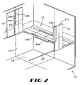
- the pair of deck panels 20 and 21 are mounted on the side walls 14 by one or more anchors mounted to each of the side walls. In one embodiment, these anchors are horizontal rails 22 that generally run the length of truck trailer 12 .
- the deck panels 20 and 21 are maintained in their upright position by locks (not shown) provided on the walls 14 of the truck trailer 12 .
- the deck panels 20 and 21 are fitted with notched mounting brackets 23 that are designed to hook over horizontal rails 22 . In this way, the deck panels 20 and 21 may rotate about horizontal rails 22 between a stored upright position and an extended horizontal deployed position, both as shown in Figure 2.
- the deck panels 20 and 21 have free ends 20a and 21a , respectively. When the deck panels 20 and 21 are deployed and their respective free ends 20a and 21a are adjacent, the deck panels 20 and 21 at least partially define a platform in truck trailer 12 above the floor 18 .
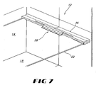
- the deck support system 10 also includes a support bracket 24a , which is preferably removably mounted between each pair of extended deck panels 20 and 21 to both interlock the pairs of deck panels 20 and 21 together and provide support to the pairs of deck panels 20 and 21 .
- the interlocking support bracket 24 has an elongated body and preferably is of a rectangular cross section.
- the support bracket 24 includes a first side 26 defining a longitudinally extended channel 28 .
- the support bracket 24 also includes a second side 30 defining a longitudinally extending support ledge 32 .
- the longitudinally extending channel 28 has an upper lip 29 and a lower lip 31 .
- the lips 29 and 31 preferably extend the length of channel 28 .
- the longitudinally extending channel 28 of support bracket 24 preferably engages the edge of deck panels 20 and 21 by virtue of the upper lip 29 and the lower lip 31 .
- the upper lip 29 and the lower lip 31 engage a series of grooves in deck panels 20 and 21 .
- the deck panel 20 includes an upper groove 33a and a lower groove 33b
- the deck panel 21 includes an upper groove 35a and a lower groove 35b .
- a stop in the form of a stop bracket 24b is affixed to the panel 20 and stops the sliding action of the support bracket 24a in an optimal position.
- the stop bracket 24b preferably is formed with the same cross section as that of the support bracket 24a .
- the stop include a nib or protrusion formed on the panel, a screw head protruding from the surface of the panel, or similar means for limiting the linear travel of the support bracket 24a .
- the support bracket 24a By engaging the deck panels 20 and 21 in this way, the support bracket 24a is capable of linear travel across the faces of deck panels 20 and 21 when the deck panels are deployed.
- the longitudinally extending channel 28 of the support bracket 24a interlocks the deployed deck panels 20 and 21 and the longitudinally extending support ledge 32 provides support to further pairs of adjacent deployed deck panels 20' and 21' as shown in Figure 11.
- the grooves 35a, 35b are at least as long as the support bracket 24 , so that the bracket 24 can be stored with the deck panel 21 without protruding past its free end 21a .
- a secondary platform in truck trailer 12 may be constructed using the above described embodiment of the deck support system 10 by first securing a starter panel 36 to the horizontal rails 22 between the vertical walls 14 and against the forward part of truck trailer 12 as shown in Figure 7.
- starter panel 36 is secured against the forward part of the truck trailer 12
- starter panel 36 may be installed at any location in the trailer 12 where the user desires to start building a secondary platform within the truck trailer 12 .
- starter panel 36 is a continuous shelf that extends between the vertical walls 14 .
- a bracket 38 may next be secured to starter panel 36 so that support ledge 32 provides a way to support subsequent deployed deck panels 20 and 21 .
- the first bracket 38 is preferably rigidly secured to starter panel 36 , but alternatively may be slidably secured thereon such as by a lip and groove design and positioned using a stop bracket. As shown in Figure 8, after the bracket 38 is in place, the deck panel 21 is rotated from its upright position against wall 14 to its deployed position, resting on the bracket 38 .
- a simple flange may be attached to the forward trailer wall to support the first pair of deck panels to provide the same function as support ledge 32 .
- a support bracket 24 is slid over the deck panel 21 to prepare for the horizontal deployment of the deck panel 20 on the opposite side wall of truck trailer 12 .
- the support bracket 24 may either stored somewhere on the trailer and be slid over the deck panel 21 (as described) or may be included on the deck panel 21 while the deck panel 21 is in its upright position. It will be seen that in the upright position of the panel 21 , each bracket 24 assists in holding the next adjacent panel (towards the rear of the trailer) against the trailer sidewall. This is also true of the preferred stop bracket with respect to holding adjacent deck panels against the opposite side wall.
- the support bracket 24a is slid onto the deck panel 21 out of the way of the deck panel 20 , and then the deck panel 20 is deployed to its horizontal position. The support bracket 24a is then slid back until it engages both deck panel 20 and deck panel 21 .
- the stop bracket 24b ensures that the support bracket 24a is slid back to the proper position with roughly half the length of the support bracket on one panel 21' and the other half on the other panel 20' .
- the support bracket 24a engages the deck panels 20 and 21 by virtue of the engagement of upper lip 29 and lower lip 31 on the support bracket 24a with the upper groove 33a and lower groove 33b of deck panel 20 , and the upper groove 35a and lower groove 35b of deck panel 21 .
- the support bracket 24a can travel further onto deck panel 21 and completely out of the way of the deck panel 20 .
- the support bracket 24a engages the deck panel 20 , preferably it may only travel far enough to provide complete engagement between the deck panel 20 and the deck panel 21 .
- Proper positioning of the support bracket is facilitated by the stop bracket 24b .
- the support bracket 24a is slid back onto the deck panel 20 so that it slidably engages both deck panels 20 and 21 and locks them together. This process is repeated, as demonstrated in Figure 11, until the desired number of deck panels are extended from their vertical position so that a sufficient amount of secondary platform space is created in truck trailer 12 for the storage of articles.
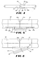
- the support bracket 24 does not include an upper lip 29 and lower lip 31 and the deck panels 20 and 21 do not include a series of grooves. Instead, the support bracket 24 includes only a longitudinally extending channel 28 and a longitudinally extending support ledge 32 .
- support bracket 24 is rotatably secured to one of the two deck panels 20 and 21 of the pair. This may be done, for example, by a pivot pin 34 secured through the first side 26 of support bracket 24 .
- the support bracket 24 can be rotated into position to interlock the deck panels 20 and 21 when the deck panels 20 and 21 are deployed to the horizontal position, thereby providing the interlocking and support for the deck panels 20 and 21 . Because the support bracket 24 is rotated into position, the stop bracket is not required in this embodiment to limit sliding movement of the support bracket. Nevertheless, a stop bracket may be used to facilitate support of the next adjacent panels 19 in an upright position described above and as shown in Figure 2.
- a secondary platform in truck trailer 12 may be constructed using the deck support system 10 by first securing a starter panel 36 to the horizontal rails 22 between the vertical walls 14 and against the forward part of truck trailer 12 as shown in Figure 7.
- starter panel 36 is a continuous shelf that extends between the walls 14 .
- a bracket 38 may next be secured to starter panel 36 so that support ledge 32 provides a way to support subsequent deployed deck panels 20 and 21 .
- the deck panel 21 is rotated from its upright position against wall 14 , with the support bracket 24 pivotably secured to the panel 21 , to its deployed position, resting on the bracket 38 .
- the support bracket 24 is rotated out of the way of the path of rotation of the deck panel 20 to prepare for the horizontal deployment of the deck panel 20 .
- the deck panel 20 is then deployed to its horizontal position and the support bracket 24 is rotated into position, as demonstrated in Figure 6, so that it engages both the deck panel 20 and the deck panel 21 and provides a support ledge for subsequently deployed deck panels. Again, this process is repeated until the desired number of deck panels are extended from their vertical position so that a sufficient amount of secondary floor space is created in truck trailer 12 for the storage of articles.
- FIGs 12 through 15 show an alternative system for pivotally mounting deck panels to the side walls 14 of the freight compartment.
- An alternative deck panel 50 which can be made of 30% glass filled nylon, or any other suitable plastic, metal, or composite material, is shown in Figure 12.
- a light-weight molded synthetic deck panel in which the ends are capped may be preferred.
- a hinge member 55 is mounted or formed along the end of the deck panel 50 that is to be connected to the side wall 14 .
- the hinge member includes one or more blocks 57 and a plurality of somewhat flexible fingers 60 and 61 spaced along each block 57 .
- a portion of a block 57 is shown in Figure 18.
- the fingers 60 are arcuate, and may lie along a portion of a circle.
- the similar fingers 61 curve in the opposite direction to the fingers 60 and may be positioned along the block 57 either even with or alternating with the fingers 60 . If directly opposite one another, the length of the respective fingers should be such that they do not interfere with one another when flexing as described below.
- the block 57 is sized to be received in a cavity 63 formed in the end of the panel 50 .
- the interior surfaces of the cavity define a space within which mating areas of the block can slide.
- the block 57 is pulled back against an interior wall or stop of the cavity 63 by a spring 65 , or other elastic member, strong enough to hold the block firmly in the cavity during routine operation of the deck system between the stowed and deployed configurations.
- a spring 65 or other elastic member, strong enough to hold the block firmly in the cavity during routine operation of the deck system between the stowed and deployed configurations.
- a spring 65 or other elastic member, strong enough to hold the block firmly in the cavity during routine operation of the deck system between the stowed and deployed configurations.
- Each spring may extend from a post 66 within the block 57 , through an opening 67 in the block.
- the interior wall may have an opening (not shown) through which the spring extends to be secured to a reinforced member 64 within the panel 50 shown in dashe
- the alternative system for pivotally mounting deck panels to the side walls 14 also includes a support member 75 which may be an aluminum extrusion or a formed, molded, or assembled part of any suitable material.
- the support member 75 as shown in Figures 12-16 defines a vertical wall 77 adapted to be secured to the side wall 14 by any suitable means.
- Another embodiment of the support member 75 is shown mounted on a side wall 14 in Figure 17.
- the support member 75 has an open back portion and vertical wall portions 77a and 77b which can engage the side wall at upper and lower extremes of the support member.
- a lower wall 78 angles upwardly to a horizontal ledge 80 . From the ledge 80 , a vertical wall 84 extends up to a pocket 86 .
- a second ledge 82 is defined at the opposite side of the pocket 86 , and extends to the vertical wall 77 , or the portion 77a in the case of the embodiment shown in Figure 17.
- the width of the ledge 80 preferably is not larger than the thickness of the deck panel 50 , as shown in Figure 14, so that the ledge does not protrude into the compartment any farther than the stowed deck panel.
- the ledge 80 bears the weight of the deployed deck panel 50 as shown in Figure 13, and the ledge 82 bears the weight of the deck panel 50 when stowed, as shown in Figure 14.
- the ledges prevent the hinge fingers 60 and 61 from bearing such weight.
- the pocket 86 is shown as an elongate channel forming part of a circle in cross section.
- the partial circle of the pocket extends beyond 180 degrees to lips 88 and 89 of the pocket 86 (marked in Figure 14), allowing the pocket 86 to trap the arcuate fingers 60 and 61 when they are forced to flex and snap into the pocket 86 .
- the deck panel 50 is sufficiently light in weight and the fingers 60 and 61 are of a flexibility selected so that one person can manipulate a deck panel to a position in which the line of fingers aligns with the elongate pocket 86 , and can force the fingers to snap into the pocket (or remove the fingers from the pocket for disassembly).
- the profile of the pocket need not be part of a circle or form a smooth curve.
- the fingers need not be circular or arcuate, and alternatively each pair of fingers 60 and 61 could be replaced by any compressible member or assembly capable of being forced into and retained movably within the pocket for functioning as a hinge.
- two or more separate pockets could be provided spaced along the end of the deck panel 50 , with hinge members on the panel at mating locations.
- the block could be an elongate structure, or separated blocks could be received in separate cavities in the panel.
- the support member 75 is shown in Figures 12-16 with internal reinforcing web structures. These may not be needed depending on the weight of items being transported, and are not present in the embodiment shown in Figure 17. Also, the portion of the vertical wall 77 below the ledge 82 may be omitted.
- a block 57' may be positioned in a cavity formed symmetrically within a deck panel 50' .
- the fingers 60 and 61 are mounted asymmetrically to the block, resulting in the deck panel, the fingers 60 and 61 , and the support member 75 having the same relative orientation as shown in Figures 13 and 14.
- the purpose for this alternative is to allow the deck panel 50' to be made in two symmetrical "clamshell" halves with half of the cavity 63 in each half of the deck panel. From the foregoing, assembly and use of a deck panel supported according to the embodiment as shown in Figures 12-18 will be apparent to those skilled in the art.
- the hinge members 55 are placed within the portion of a cavity 63 formed in a half of a deck panel 50 or 50' , and a spring is connected between the post 66 and the reinforced member 64 . Then the other half of the deck member is engaged to complete the deck member and form the cavity 63 with the flexible fingers 60 and 61 protruding.
- a support member 75 is attached to a side wall 14 of a compartment, usually in a horizontal orientation. Given a preferred construction of the support member and the deck hinge member, one person can manipulate the flexible fingers into alignment along the pocket or pockets 86 of the support member, and force the fingers to snap into the pocket. The installed configuration is shown in Figures 13, 14, and 16.
- the deck panel now can be rotated about the hinge axis from a stowed configuration shown in Figure 14 to a deployed configuration shown in Figure 13.
- the relative positioning, central support, and locking of a plurality of the deck panels 50 or 50' within a freight compartment can be done according to the systems described above in connection with Figures 1-11.
- the hinge member includes an elongate, arcuate member 90 attached to each block 57 at the same positions as fingers 60, 61 in an earlier embodiment.
- the arcuate member 90 lies along a portion of a circle, defining a gap 96 at an angle from a perpendicular extending from the face of the block 57 .
- a locking plunger 91 is provided and shaped for sliding movement within the slot 95 .
- An outer surface of the plunger 91 is curved at the same radius as the hinge 90 .
- the hinge member 90 is preferably made from a rigid material, such as extruded aluminum or a plastic-based material.
- the locking plunger in Figure 19 is illustrated as fully mated, that is, fully extended outwards from the center of the circle formed by the rigid circular member 90 .
- the assembly of the circular member 90 and the locking plunger 91 form a largely complete circle that is designed to pivot inside the pocket 86 when inserted.
- the diameter of the largely complete circle when measured along the path of the locking plunger 91 is illustrated as d 2 .
- the distance d 2 varies based on the position of the plunger 91 .
- the diameter of the largely completed circle not intersecting the gap 96 is illustrated as d 1 and does not vary with the position of the plunger 91 .
- the diameter of d 2 is equal to d 1 .
- the locking plunger 91 is held in the mated position by one of a variety of methods. Illustrated in Figure 19 is a spring 94 positioned between the circular member 90 and the locking plunger 91 so that the springs pushes the locking plunger against the circular member.
- the spring may be maintained in its position in a conventional manner using nibs 92 present on the locking plunger and on the inside surface of the acuate member.
- Another embodiment for maintaining the locking plunger 91 in a fully mated position is to use a set screw (not shown) extending into the hinge member from approximately opposite the gap 96 , to push the locking plunger against the circular member.
- the locking plunger must be in a partially mated position in order to insert the hinge into the pocket assembly as illustrated in Figure 20.
- the pocket 86 forms a semi-circular structure greater than 180 degrees and is bounded by the edges or lips of the pocket 93a, 93b
- the pocket opening is the distance between the lips 93a, 93b and is less than the inside diameter of the pocket
- the outside diameter d 1 formed by the circular member 90 is slightly smaller than the inside diameter of the pocket 86 but greater than the pocket opening such that insertion or removal of the hinge assembly is not possible when the locking plunger 91 is fully mated or the hinge 90 is oriented with the full diameter d 1 facing the opening of the pocket 86.
- FIG. 20 depicts the insertion of the hinge into the pocket with the locking plunger partially mated.
- the insertion of the hinge requires the hinge and deck panel assembly to be at a certain angle so that the diameter d 2 of the hinge is presented and allowed to pass though the opening of the pocket
- the pocket lip 93a pushes against the locking plunger 91 forcing it inward such that d 2 is less than d 1 .
- the spring 94 is compressible and the locking plunger maintains contact with the pocket lip 93a while it compresses the spring 94 . Because insertion or removal requires compression of the spring, a measure of lateral force is required for the hinge to be inserted.
- the spring forces the locking plunger back into the fully mated position such that d 2 is equal to d 1 , allowing the hinge to be rotated.
- the hinge assembly is retained within the pocket because a full diameter d 1 is presented to the pocket opening.
- the diameter d 1 is does not vary and is greater than the pocket opening. If a locking set screw is used to position the locking plunger, the screw can be advanced after the hinge is inserted to mate the locking plunger for smooth rotation of the hinge.
- the hinge can comprise solely the partial circular rim of the hinge 90 without any locking plunger and spring. This allows insertion and removal of the hinge at a specific angle without any force. The specific angle is obtained when the diameter as defined by d 3 is opposite to the opening of the pocket (not shown). Once the hinge is fully inserted and is rotated to a horizontal or vertical position, the diameter of the hinge 90 as defined by d 1 is retained within the pocket by the lips 93a, 93b of the pocket. In use of this embodiment, care should be taken not to exert a withdrawing force on the deck panel while it is being rotated between its stowed and deployed positions.
Landscapes
- Engineering & Computer Science (AREA)
- Mechanical Engineering (AREA)
- Transportation (AREA)
- Chemical & Material Sciences (AREA)
- Combustion & Propulsion (AREA)
- Body Structure For Vehicles (AREA)
- Vehicle Step Arrangements And Article Storage (AREA)
- Fittings On The Vehicle Exterior For Carrying Loads, And Devices For Holding Or Mounting Articles (AREA)
- Auxiliary Methods And Devices For Loading And Unloading (AREA)
- Pivots And Pivotal Connections (AREA)
Claims (21)
- Structure de charnière détachable, comprenant :un premier élément (75) définissant une poche (86) à l'intérieur de celui-ci, dans lequel ladite poche est un canal de forme allongée définissant un axe de pivot respectif, etun deuxième élément (55) définissant une saillie (60) arquée relativement flexible dimensionnée et formée pour s'insérer par encliquetage et être retenue dans ladite poche de façon à permettre un mouvement pivotant dudit premier élément par rapport audit deuxième élément autour dudit axe de pivot, ledit deuxième élément comprenant une pluralité desdites saillies arquées flexibles connectées à une base, caractérisée en ce que lesdites saillies arquées flexibles comprennent des doigts (60, 61) arqués qui s'étendent trouvent le long d'une partie d'un cercle et sont attachés à une extrémité à ladite base, lesdits doigts arqués comprenant au moins un doigt arqué (60) ayant une direction de courbure à l'opposé d'une direction de courbure d'au moins un autre doigt arqué (61).
- Structure de charnière selon la revendication 1, dans laquelle lesdites saillies arquées (60) flexibles sont d'une flexibilité sélectionnée de sorte qu'une personne peut forcer la saille arquée flexible pour qu'elle s'insère par encliquetage dans ladite poche et soit extraite de celle-ci.
- Structure de charnière selon la revendication 1 ou la revendication 2, dans laquelle ledit canal a une section transversale partiellement circulaire s'étendant au-delà de 180 degrés de façon à permettre à ladite poche d'emprisonner lesdites saillies arquées flexibles quand lesdites saillies arquées flexibles sont fléchies et encliquetées de force dans ladite poche.
- Structure de charnière d'une quelconque revendication précédente, dans laquelle ledit canal (86) définit une ouverture allongée à travers laquelle lesdits doigts s'étendent, ladite ouverture étant suffisamment large pour permettre audit deuxième élément de pivoter d'une position généralement horizontale sur une position généralement verticale.
- Système de support ayant une structure de charnière selon une quelconque revendication précédente et destinée à monter de façon pivotante un panneau de plancher sur une paroi latérale d'un compartiment de fret, ledit compartiment de fret (12) ayant :un plancher (18) et au moins deux parois latérales espacées (14, 16) ;un panneau (50) de plancher ayant ledit deuxième élément (55) associé avec celui-ci ; etun élément (75) de support, s'étendant généralement horizontalement le long d'une desdites parois latérales, et comprenant ledit premier élément,par lequel le mouvement pivotant dudit panneau (50) de plancher par rapport audit élément (75) de support est autorisé.
- Système de support selon la revendication 5, dans lequel ledit élément (75) de support définit un premier appui (80) dans lequel ledit premier appui est positionné pour engager ledit panneau (50) de plancher dans une configuration déployée de façon à isoler sensiblement ledit deuxième élément (55) du poids dudit panneau (50) de plancher et des articles qui, lors de son utilisation, sont placés sur celui-ci.
- Système de support selon la revendication 6, dans lequel ledit élément de support définit un deuxième appui (82), dans lequel ledit deuxième appui est positionné pour supporter le poids dudit panneau (50) de plancher quand il est arrimé généralement verticalement contre ladite paroi latérale de façon à isoler sensiblement ledit deuxième élément (55) du poids dudit deuxième panneau de plancher.
- Système de support selon l'une quelconque des revendications 5 à 7, dans lequel ledit deuxième élément (55) est supporté de façon amovible par ledit panneau (50) de plancher de façon à ce que ledit deuxième élément puisse se déplacer par rapport audit panneau de plancher quand ledit plateau de plancher est déployé, un tel déplacement ayant un composant de déplacement perpendiculaire à ladite paroi latérale.
- Système de support selon la revendication 8, dans lequel ledit deuxième élément (55) comprend au moins un bloc dimensionné de manière à être reçu dans une cavité (63) formée dans une extrémité dudit panneau de plancher.
- Système de support selon la revendication 9, dans lequel ledit au moins un bloc (57) comprend une structure allongée unique dimensionnée de manière à être reçue dans une cavité formée dans une extrémité dudit panneau de plancher.
- Système de support selon la revendication 12, dans lequel ledit au moins un bloc (57) comprend une pluralité de blocs séparés dimensionnés pour être reçus dans des cavités séparées formées dans une extrémité dudit panneau de plancher.
- Système de support selon la revendication 11, dans lequel ledit au moins un bloc est rétracté contre une paroi intérieure de ladite cavité par au moins un élément élastique.
- Système de support selon l'une quelconque des revendications 5 à 12 dans lequel :un premier panneau (21) de plancher est monté de façon pivotante sur l'une desdites parois latérales et est capable d'être positionné dans une position arrimée verticale et dans une position déployée horizontale, ledit panneau de plancher comprenant un bord latéral s'étendant vers l'extérieur à partir de la paroi latérale, et un appui (24a) faisant saillie à partir dudit bord latéral dans une position déployée ; etun deuxième panneau (21') de plancher est monté de façon pivotante sur ladite paroi latérale, adjacente audit premier panneau de plancher, et peut être positionné dans une position arrimée verticale et dans une position déployée horizontale dans lesquelles ledit appui dudit premier panneau de plancher dans une position déployée est configuré pour supporter ledit deuxième panneau de plancher dans une position déployée.
- Système de support selon la revendication 13, dans lequel ledit appui (24a) est mobile en translation sur ledit bord latéral dudit premier panneau de plancher.
- Système de support selon la revendication 13, dans lequel ledit appui (24a) est mobile en rotation sur ledit bord latéral dudit premier panneau de plancher.
- Système de support selon la revendication 13, dans lequel ledit appui (24a) est fixé sur ledit appui latéral dudit premier panneau de plancher.
- Structure de charnière selon la revendication 1, ladite saillie arquée flexible (60) ayant un piston (91) positionné à l'intérieur dudit deuxième élément (55) et pouvant être déplacé par rapport à un espace dans une surface périphérique de ladite saillie (60), ladite saillie étant dimensionnée et formée pour être insérée par encliquetage dans ladite poche et être retenue à l'intérieur de celle-ci par un mouvement dudit piston (91), de façon à permettre le mouvement pivotant dudit premier élément par rapport audit deuxième élément autour dudit axe de pivot.
- Structure de charnière selon la revendication 17 dans laquelle ledit piston (91) est positionné par l'utilisation de l'un parmi le groupe d'une vis et d'un ressort (94).
- Structure de charnière selon la revendication 17 et la revendication 18 dans laquelle ledit deuxième élément est dimensionné et formé pour être inséré dans ladite poche quand il est disposé selon un premier angle relatif sur le premier élément et retenu à l'intérieur de ladite poche lorsqu'il est disposé selon un deuxième angle relatif sur le premier élément.
- Structure de charnière selon la revendication 19 dans laquelle ladite saillie est conçue pour être retenue à l'intérieur de ladite poche le long de la portée entière du mouvement pivotant dudit premier élément par rapport audit deuxième élément après avoir été insérée dans ladite poche.
- Structure de charnière selon l'une quelconque des revendications 17 à 20 dans laquelle ledit piston (91) possède une section transversale semi-circulaire.
Applications Claiming Priority (5)
| Application Number | Priority Date | Filing Date | Title |
|---|---|---|---|
| US38266002P | 2002-05-21 | 2002-05-21 | |
| US382660P | 2002-05-21 | ||
| US10/353,266 US6854400B2 (en) | 2002-05-21 | 2003-01-29 | Hinge and support system for an intermediate deck in a trailer |
| US353266 | 2003-01-29 | ||
| PCT/US2003/008333 WO2003099639A1 (fr) | 2002-05-21 | 2003-03-18 | Systeme de charniere et de support pour un plateau intermediaire d'une remorque |
Publications (2)
| Publication Number | Publication Date |
|---|---|
| EP1507695A1 EP1507695A1 (fr) | 2005-02-23 |
| EP1507695B1 true EP1507695B1 (fr) | 2008-02-06 |
Family
ID=29553145
Family Applications (1)
| Application Number | Title | Priority Date | Filing Date |
|---|---|---|---|
| EP03755062A Expired - Lifetime EP1507695B1 (fr) | 2002-05-21 | 2003-03-18 | Système de charnière et du support pour un plateau intermédiaire d'une remorque |
Country Status (11)
| Country | Link |
|---|---|
| US (2) | US6854400B2 (fr) |
| EP (1) | EP1507695B1 (fr) |
| JP (1) | JP4199190B2 (fr) |
| CN (1) | CN100391776C (fr) |
| AT (1) | ATE385489T1 (fr) |
| AU (1) | AU2003225854A1 (fr) |
| CA (1) | CA2485330C (fr) |
| DE (1) | DE60318999T2 (fr) |
| ES (1) | ES2300606T3 (fr) |
| MX (1) | MXPA04011517A (fr) |
| WO (1) | WO2003099639A1 (fr) |
Families Citing this family (26)
| Publication number | Priority date | Publication date | Assignee | Title |
|---|---|---|---|---|
| US6910668B2 (en) * | 2001-06-12 | 2005-06-28 | Aero Industries, Inc. | Molded deck board |
| US6854400B2 (en) * | 2002-05-21 | 2005-02-15 | United Parcel Service Of America, Inc. | Hinge and support system for an intermediate deck in a trailer |
| WO2005080231A1 (fr) * | 2004-01-30 | 2005-09-01 | Mark James Long | Conteneur |
| US7370899B2 (en) * | 2004-10-07 | 2008-05-13 | Tropicana Products, Inc. | Retractable lading support |
| US7293813B2 (en) * | 2005-05-11 | 2007-11-13 | Jerrell P Squyres | Double jointed hinge and foldable deck using same |
| US20080012372A1 (en) * | 2006-07-14 | 2008-01-17 | Squyres Jerrell P | Foldable Deck |
| US20080112771A1 (en) * | 2006-11-13 | 2008-05-15 | Pamela Ann Barney | Shipping decks for transporting cargo |
| US7854468B2 (en) * | 2008-02-12 | 2010-12-21 | Aero Industries, Inc. | Self-deploying drag reducing device |
| US20110127396A1 (en) * | 2009-11-30 | 2011-06-02 | Ethan Parker | Wall hanging inventory control and packaging system |
| NO336204B1 (no) * | 2010-09-17 | 2015-06-15 | Smartbar Nuf | Transporterbar skranke |
| US8540299B2 (en) * | 2011-09-25 | 2013-09-24 | GM Global Technology Operations LLC | Convertible space system for interior cargo area of a vehicle |
| US9517730B2 (en) * | 2012-04-10 | 2016-12-13 | Tekmodo, Llc | Panel shelf system |
| FR2993253A1 (fr) * | 2012-07-11 | 2014-01-17 | Christophe Robert Herve | Dispositif de stockage amovible et reglable en hauteur arrime a toute paroi verticale le permettant |
| CN102897448A (zh) * | 2012-11-07 | 2013-01-30 | 浙江双友物流器械股份有限公司 | 一种用于货箱内的分层装置 |
| US9359015B2 (en) * | 2012-12-10 | 2016-06-07 | Globe Composite Solutions, Ltd. | Hinged load panel for package delivery vehicles |
| US9139125B2 (en) * | 2013-12-10 | 2015-09-22 | GM Global Technology Operations LLC | Coupling assembly |
| US9376048B2 (en) * | 2014-02-11 | 2016-06-28 | Globe Composite Solutions, Ltd. | Stowable floor assembly for package delivery vehicles |
| US20160116213A1 (en) * | 2014-10-27 | 2016-04-28 | PeerSouth, Inc. | Drying trailer |
| US9702175B2 (en) | 2015-05-13 | 2017-07-11 | Hyundai Translead | Hinge and locking device |
| WO2018056265A1 (fr) * | 2016-09-20 | 2018-03-29 | オールセーフ株式会社 | Système de rayonnage, unité de plaque de rayonnage et procédé d'utilisation de système de rayonnage |
| WO2019013985A1 (fr) * | 2017-07-11 | 2019-01-17 | Walmart Apollo, Llc | Système de compartiment de camion réglable |
| CN109130979A (zh) * | 2018-09-20 | 2019-01-04 | 朱广军 | 一种车厢内多用途的支撑装置 |
| DE102019114002B3 (de) * | 2019-05-24 | 2020-11-12 | Behr-Hella Thermocontrol Gmbh | Bedieneinheit für ein Fahrzeug |
| CO2019010919A1 (es) * | 2019-10-01 | 2021-04-08 | Pontificia Univ Javeriana | Mecanismo de carga y descarga de materiales para un contenedor |
| US11878724B2 (en) | 2020-07-29 | 2024-01-23 | Gunderson Llc | Autorack cars |
| CN115257502B (zh) * | 2022-07-31 | 2024-06-11 | 上交(徐州)新材料研究院有限公司 | 一种可变多层自装卸物流车 |
Citations (1)
| Publication number | Priority date | Publication date | Assignee | Title |
|---|---|---|---|---|
| DE3514765A1 (de) * | 1985-04-24 | 1986-10-30 | Bayerische Motoren Werke AG, 8000 München | Aufnahmeteil mit wenigstens einem spreizduebel zum loesbaren befestigen an einem halteelement |
Family Cites Families (34)
| Publication number | Priority date | Publication date | Assignee | Title |
|---|---|---|---|---|
| US355277A (en) | 1886-12-28 | newell | ||
| US2605912A (en) | 1947-09-25 | 1952-08-05 | Lilly Co Eli | Mechanism for transporting loads |
| US2584506A (en) | 1949-06-17 | 1952-02-05 | Earl W Shreve | Freight support structure for trucking vans and the like |
| US3000666A (en) | 1960-08-30 | 1961-09-19 | Rail Trailer Co | Protective devices for doors of shipping containers |
| US3680491A (en) | 1967-12-13 | 1972-08-01 | Evans Prod Co | Freight bracing system |
| JPS5242965B2 (fr) | 1972-09-07 | 1977-10-27 | ||
| US3875871A (en) | 1973-03-29 | 1975-04-08 | Acf Ind Inc | Multi-level transportation vehicle |
| US3911832A (en) | 1973-09-10 | 1975-10-14 | Craft Ind Inc Van | Deck structure for vehicles |
| US3897971A (en) | 1974-06-17 | 1975-08-05 | Ddt Inc | Trailer installation |
| US3905309A (en) | 1974-09-12 | 1975-09-16 | Leslie D Suter | Second deck system |
| US4079677A (en) | 1975-07-09 | 1978-03-21 | Vandergriff Buford E | Adjustable cargo bracing bar |
| US4094546A (en) | 1976-10-26 | 1978-06-13 | Pullman Incorporated | Roll away decking system |
| US4191109A (en) | 1978-02-16 | 1980-03-04 | Transco Inc. | End fitting for cargo containers |
| DE2960727D1 (en) | 1978-05-25 | 1981-11-26 | Bkl Extrusions Ltd | Load carrying decks |
| US4281870A (en) | 1979-08-06 | 1981-08-04 | Evans Products Company | Vehicle convertible double deck system |
| SE460492B (sv) * | 1985-01-09 | 1989-10-16 | Ege Westin Ab | Laenkanordning |
| US4659132A (en) | 1986-02-14 | 1987-04-21 | The Coca-Cola Company | Convertible beverage body for delivery truck or trailer |
| GB8612857D0 (en) * | 1986-05-27 | 1986-07-02 | Norfrost Ltd | Plastic hinge |
| US4995322A (en) | 1986-12-04 | 1991-02-26 | Frederick Percy R | Externally mounted R.V. table |
| US4942271A (en) * | 1988-12-07 | 1990-07-17 | Hubbell Incorporated | Hinged plastic duct for conduit |
| US5042863A (en) | 1990-08-09 | 1991-08-27 | Fraga Otto F | Portable storage assembly |
| US5261771A (en) | 1990-11-08 | 1993-11-16 | Marsch Dennis L | Multiple use freight deck |
| US5314276A (en) | 1990-11-08 | 1994-05-24 | Barone Joseph P | Lading separating and bracing means |
| GB9215324D0 (en) | 1992-07-18 | 1992-09-02 | Adams Mark W | Improvements relating to goods storage |
| GB9226006D0 (en) * | 1992-12-14 | 1993-02-10 | Hawes Signs Ltd | Hinge assembly |
| US5306064A (en) | 1993-05-10 | 1994-04-26 | Nina Padovano | Vehicle freight clamping assembly |
| US5375534A (en) | 1993-05-24 | 1994-12-27 | Adams; Thomas F. | Intermediate deck structure for vehicles |
| AUPM282693A0 (en) * | 1993-12-06 | 1994-01-06 | Harris, Maureen Anne | Mounting for movable member |
| US5505583A (en) | 1995-02-01 | 1996-04-09 | Courtesy Enterprises, Incorporated | Slope plates for particulate material truck box |
| CN1187231A (zh) * | 1995-04-18 | 1998-07-08 | 皇家集团技术有限公司 | 挤压成型的铰接部件和由此形成的折叠门 |
| US6170897B1 (en) | 1997-02-27 | 2001-01-09 | Robert B. Karrer | Cargo anchoring and protection system including bed liner |
| US6131320A (en) * | 1997-10-14 | 2000-10-17 | American Allsafe Company | Floor sign |
| US6585306B1 (en) * | 2002-02-01 | 2003-07-01 | United Parcel Service Of America, Inc. | Interlocking deck support system |
| US6854400B2 (en) * | 2002-05-21 | 2005-02-15 | United Parcel Service Of America, Inc. | Hinge and support system for an intermediate deck in a trailer |
-
2003
- 2003-01-29 US US10/353,266 patent/US6854400B2/en not_active Expired - Lifetime
- 2003-03-18 CA CA002485330A patent/CA2485330C/fr not_active Expired - Lifetime
- 2003-03-18 WO PCT/US2003/008333 patent/WO2003099639A1/fr active IP Right Grant
- 2003-03-18 DE DE60318999T patent/DE60318999T2/de not_active Expired - Lifetime
- 2003-03-18 EP EP03755062A patent/EP1507695B1/fr not_active Expired - Lifetime
- 2003-03-18 MX MXPA04011517A patent/MXPA04011517A/es active IP Right Grant
- 2003-03-18 ES ES03755062T patent/ES2300606T3/es not_active Expired - Lifetime
- 2003-03-18 CN CNB038115190A patent/CN100391776C/zh not_active Expired - Lifetime
- 2003-03-18 AU AU2003225854A patent/AU2003225854A1/en not_active Abandoned
- 2003-03-18 AT AT03755062T patent/ATE385489T1/de not_active IP Right Cessation
- 2003-03-18 JP JP2004507309A patent/JP4199190B2/ja not_active Expired - Fee Related
-
2004
- 2004-10-29 US US10/978,253 patent/US7549380B2/en not_active Expired - Lifetime
Patent Citations (1)
| Publication number | Priority date | Publication date | Assignee | Title |
|---|---|---|---|---|
| DE3514765A1 (de) * | 1985-04-24 | 1986-10-30 | Bayerische Motoren Werke AG, 8000 München | Aufnahmeteil mit wenigstens einem spreizduebel zum loesbaren befestigen an einem halteelement |
Also Published As
| Publication number | Publication date |
|---|---|
| CA2485330C (fr) | 2009-12-15 |
| EP1507695A1 (fr) | 2005-02-23 |
| CN1655979A (zh) | 2005-08-17 |
| WO2003099639A1 (fr) | 2003-12-04 |
| CA2485330A1 (fr) | 2003-12-04 |
| MXPA04011517A (es) | 2005-02-14 |
| JP4199190B2 (ja) | 2008-12-17 |
| JP2005526662A (ja) | 2005-09-08 |
| AU2003225854A1 (en) | 2003-12-12 |
| US20030217670A1 (en) | 2003-11-27 |
| US7549380B2 (en) | 2009-06-23 |
| ATE385489T1 (de) | 2008-02-15 |
| ES2300606T3 (es) | 2008-06-16 |
| DE60318999D1 (de) | 2008-03-20 |
| US20070062003A1 (en) | 2007-03-22 |
| US6854400B2 (en) | 2005-02-15 |
| CN100391776C (zh) | 2008-06-04 |
| DE60318999T2 (de) | 2009-01-29 |
Similar Documents
| Publication | Publication Date | Title |
|---|---|---|
| EP1507695B1 (fr) | Système de charnière et du support pour un plateau intermédiaire d'une remorque | |
| EP1470037B1 (fr) | Systeme de support de panneaux de plancher interverrouilles | |
| US7607874B2 (en) | System and method for partitioning cargo areas | |
| US6648569B2 (en) | Vehicle cargo bed with movable platform | |
| US20060279099A1 (en) | Cargo management system and apparatus | |
| US6827231B2 (en) | Minivan box liner | |
| US20070164540A1 (en) | Container | |
| GB2247651A (en) | Divider apparatus | |
| US6575679B2 (en) | Secure accessory system for a truck box | |
| EP0005960B1 (fr) | Planchers porteurs de charge | |
| US20040050889A1 (en) | Cargo management system useful as a table | |
| EP3339069B1 (fr) | Support pliant pour plier une bâche et construction pour suspendre la bâche | |
| US20220219590A1 (en) | Cargo stacking devices and systems | |
| KR100662544B1 (ko) | 실내공간이 확장되는 다기능 컨테이너 | |
| US10744925B1 (en) | Truck bed load organizer | |
| KR200372272Y1 (ko) | 실내공간이 확장되는 다기능 컨테이너 |
Legal Events
| Date | Code | Title | Description |
|---|---|---|---|
| PUAI | Public reference made under article 153(3) epc to a published international application that has entered the european phase |
Free format text: ORIGINAL CODE: 0009012 |
|
| 17P | Request for examination filed |
Effective date: 20041112 |
|
| AK | Designated contracting states |
Kind code of ref document: A1 Designated state(s): AT BE BG CH CY CZ DE DK EE ES FI FR GB GR HU IE IT LI LU MC NL PT RO SE SI SK TR |
|
| AX | Request for extension of the european patent |
Extension state: AL LT LV MK |
|
| DAX | Request for extension of the european patent (deleted) | ||
| 17Q | First examination report despatched |
Effective date: 20050909 |
|
| RTI1 | Title (correction) |
Free format text: HINGE AND SUPPORT SYSTEM FOR AN INTERMEDIATE DECK IN A TRAILER |
|
| GRAP | Despatch of communication of intention to grant a patent |
Free format text: ORIGINAL CODE: EPIDOSNIGR1 |
|
| GRAS | Grant fee paid |
Free format text: ORIGINAL CODE: EPIDOSNIGR3 |
|
| GRAA | (expected) grant |
Free format text: ORIGINAL CODE: 0009210 |
|
| AK | Designated contracting states |
Kind code of ref document: B1 Designated state(s): AT BE BG CH CY CZ DE DK EE ES FI FR GB GR HU IE IT LI LU MC NL PT RO SE SI SK TR |
|
| REG | Reference to a national code |
Ref country code: GB Ref legal event code: FG4D |
|
| REG | Reference to a national code |
Ref country code: CH Ref legal event code: EP |
|
| REG | Reference to a national code |
Ref country code: IE Ref legal event code: FG4D |
|
| REF | Corresponds to: |
Ref document number: 60318999 Country of ref document: DE Date of ref document: 20080320 Kind code of ref document: P |
|
| REG | Reference to a national code |
Ref country code: ES Ref legal event code: FG2A Ref document number: 2300606 Country of ref document: ES Kind code of ref document: T3 |
|
| PG25 | Lapsed in a contracting state [announced via postgrant information from national office to epo] |
Ref country code: FI Free format text: LAPSE BECAUSE OF FAILURE TO SUBMIT A TRANSLATION OF THE DESCRIPTION OR TO PAY THE FEE WITHIN THE PRESCRIBED TIME-LIMIT Effective date: 20080206 |
|
| NLV1 | Nl: lapsed or annulled due to failure to fulfill the requirements of art. 29p and 29m of the patents act | ||
| PG25 | Lapsed in a contracting state [announced via postgrant information from national office to epo] |
Ref country code: AT Free format text: LAPSE BECAUSE OF FAILURE TO SUBMIT A TRANSLATION OF THE DESCRIPTION OR TO PAY THE FEE WITHIN THE PRESCRIBED TIME-LIMIT Effective date: 20080206 |
|
| ET | Fr: translation filed | ||
| PG25 | Lapsed in a contracting state [announced via postgrant information from national office to epo] |
Ref country code: SI Free format text: LAPSE BECAUSE OF FAILURE TO SUBMIT A TRANSLATION OF THE DESCRIPTION OR TO PAY THE FEE WITHIN THE PRESCRIBED TIME-LIMIT Effective date: 20080206 |
|
| PG25 | Lapsed in a contracting state [announced via postgrant information from national office to epo] |
Ref country code: DK Free format text: LAPSE BECAUSE OF FAILURE TO SUBMIT A TRANSLATION OF THE DESCRIPTION OR TO PAY THE FEE WITHIN THE PRESCRIBED TIME-LIMIT Effective date: 20080206 Ref country code: CZ Free format text: LAPSE BECAUSE OF FAILURE TO SUBMIT A TRANSLATION OF THE DESCRIPTION OR TO PAY THE FEE WITHIN THE PRESCRIBED TIME-LIMIT Effective date: 20080206 Ref country code: NL Free format text: LAPSE BECAUSE OF FAILURE TO SUBMIT A TRANSLATION OF THE DESCRIPTION OR TO PAY THE FEE WITHIN THE PRESCRIBED TIME-LIMIT Effective date: 20080206 Ref country code: MC Free format text: LAPSE BECAUSE OF NON-PAYMENT OF DUE FEES Effective date: 20080331 Ref country code: SE Free format text: LAPSE BECAUSE OF FAILURE TO SUBMIT A TRANSLATION OF THE DESCRIPTION OR TO PAY THE FEE WITHIN THE PRESCRIBED TIME-LIMIT Effective date: 20080506 Ref country code: PT Free format text: LAPSE BECAUSE OF FAILURE TO SUBMIT A TRANSLATION OF THE DESCRIPTION OR TO PAY THE FEE WITHIN THE PRESCRIBED TIME-LIMIT Effective date: 20080707 Ref country code: SK Free format text: LAPSE BECAUSE OF FAILURE TO SUBMIT A TRANSLATION OF THE DESCRIPTION OR TO PAY THE FEE WITHIN THE PRESCRIBED TIME-LIMIT Effective date: 20080206 |
|
| REG | Reference to a national code |
Ref country code: CH Ref legal event code: PL |
|
| PG25 | Lapsed in a contracting state [announced via postgrant information from national office to epo] |
Ref country code: RO Free format text: LAPSE BECAUSE OF FAILURE TO SUBMIT A TRANSLATION OF THE DESCRIPTION OR TO PAY THE FEE WITHIN THE PRESCRIBED TIME-LIMIT Effective date: 20080206 |
|
| PLBE | No opposition filed within time limit |
Free format text: ORIGINAL CODE: 0009261 |
|
| STAA | Information on the status of an ep patent application or granted ep patent |
Free format text: STATUS: NO OPPOSITION FILED WITHIN TIME LIMIT |
|
| 26N | No opposition filed |
Effective date: 20081107 |
|
| PG25 | Lapsed in a contracting state [announced via postgrant information from national office to epo] |
Ref country code: CH Free format text: LAPSE BECAUSE OF NON-PAYMENT OF DUE FEES Effective date: 20080331 Ref country code: LI Free format text: LAPSE BECAUSE OF NON-PAYMENT OF DUE FEES Effective date: 20080331 Ref country code: IE Free format text: LAPSE BECAUSE OF NON-PAYMENT OF DUE FEES Effective date: 20080318 Ref country code: EE Free format text: LAPSE BECAUSE OF FAILURE TO SUBMIT A TRANSLATION OF THE DESCRIPTION OR TO PAY THE FEE WITHIN THE PRESCRIBED TIME-LIMIT Effective date: 20080206 |
|
| PG25 | Lapsed in a contracting state [announced via postgrant information from national office to epo] |
Ref country code: BG Free format text: LAPSE BECAUSE OF FAILURE TO SUBMIT A TRANSLATION OF THE DESCRIPTION OR TO PAY THE FEE WITHIN THE PRESCRIBED TIME-LIMIT Effective date: 20080506 |
|
| PG25 | Lapsed in a contracting state [announced via postgrant information from national office to epo] |
Ref country code: CY Free format text: LAPSE BECAUSE OF FAILURE TO SUBMIT A TRANSLATION OF THE DESCRIPTION OR TO PAY THE FEE WITHIN THE PRESCRIBED TIME-LIMIT Effective date: 20080206 |
|
| PG25 | Lapsed in a contracting state [announced via postgrant information from national office to epo] |
Ref country code: HU Free format text: LAPSE BECAUSE OF FAILURE TO SUBMIT A TRANSLATION OF THE DESCRIPTION OR TO PAY THE FEE WITHIN THE PRESCRIBED TIME-LIMIT Effective date: 20080807 Ref country code: LU Free format text: LAPSE BECAUSE OF NON-PAYMENT OF DUE FEES Effective date: 20080318 |
|
| PG25 | Lapsed in a contracting state [announced via postgrant information from national office to epo] |
Ref country code: TR Free format text: LAPSE BECAUSE OF FAILURE TO SUBMIT A TRANSLATION OF THE DESCRIPTION OR TO PAY THE FEE WITHIN THE PRESCRIBED TIME-LIMIT Effective date: 20080206 |
|
| PG25 | Lapsed in a contracting state [announced via postgrant information from national office to epo] |
Ref country code: GR Free format text: LAPSE BECAUSE OF FAILURE TO SUBMIT A TRANSLATION OF THE DESCRIPTION OR TO PAY THE FEE WITHIN THE PRESCRIBED TIME-LIMIT Effective date: 20080507 |
|
| REG | Reference to a national code |
Ref country code: FR Ref legal event code: PLFP Year of fee payment: 14 |
|
| REG | Reference to a national code |
Ref country code: FR Ref legal event code: PLFP Year of fee payment: 15 |
|
| REG | Reference to a national code |
Ref country code: FR Ref legal event code: PLFP Year of fee payment: 16 |
|
| PGFP | Annual fee paid to national office [announced via postgrant information from national office to epo] |
Ref country code: GB Payment date: 20220127 Year of fee payment: 20 Ref country code: DE Payment date: 20220126 Year of fee payment: 20 |
|
| PGFP | Annual fee paid to national office [announced via postgrant information from national office to epo] |
Ref country code: IT Payment date: 20220210 Year of fee payment: 20 Ref country code: FR Payment date: 20220118 Year of fee payment: 20 Ref country code: BE Payment date: 20220221 Year of fee payment: 20 |
|
| PGFP | Annual fee paid to national office [announced via postgrant information from national office to epo] |
Ref country code: ES Payment date: 20220405 Year of fee payment: 20 |
|
| REG | Reference to a national code |
Ref country code: DE Ref legal event code: R071 Ref document number: 60318999 Country of ref document: DE |
|
| REG | Reference to a national code |
Ref country code: BE Ref legal event code: MK Effective date: 20230318 |
|
| REG | Reference to a national code |
Ref country code: GB Ref legal event code: PE20 Expiry date: 20230317 |
|
| REG | Reference to a national code |
Ref country code: ES Ref legal event code: FD2A Effective date: 20230426 |
|
| PG25 | Lapsed in a contracting state [announced via postgrant information from national office to epo] |
Ref country code: GB Free format text: LAPSE BECAUSE OF EXPIRATION OF PROTECTION Effective date: 20230317 |
|
| PG25 | Lapsed in a contracting state [announced via postgrant information from national office to epo] |
Ref country code: ES Free format text: LAPSE BECAUSE OF EXPIRATION OF PROTECTION Effective date: 20230319 |