Field of the Art
The present invention relates to a charging equipment and charging method
for a secondary battery, such as a storage battery, a nickel-cadmium battery, a
nickel metal hydride battery, a lithium-ion battery, and the like.
Background Art
Recently, the range of use of a secondary battery is remarkably increasing.
For example, the secondary battery is used as power source of an electrical
appliance, e.g., a digital camera, a digital video camera, and a notebook
computer; a communication device, e.g., a cellular phone; a power apparatus,
e.g., an electric power tool and a vacuum cleaner; or the like. The term "the
secondary battery" means a rechargeable battery that can repeat charge and
discharge cycles, and during charge, electrical energy is transformed into
chemical energy stored in the secondary battery. The stored chemical energy
is converted back into electrical energy so as to be used. A nickel-cadmium
battery, a nickel metal hydride battery, a lithium ion battery, a NAS battery,
etc. are listed as practically used secondary batteries.
Incidentally, the electromotive reaction and the discharge reaction inside
the secondary battery include chemical reaction, electric reaction, and
complicated energy conversion and energy transfer where the chemical
reaction and the electric reaction are mutually concerned. There lies time
element among these various reactions. Accordingly, the secondary battery
must be charged in consideration of the reactions, and when excessive current
flows through the secondary battery in the process of charge, the internal
structure of the secondary battery is sometimes damaged by irreversible
chemical reactions, including unexpected exothermic reaction, swelling
reaction, or the like. Even if the internal structure of the secondary battery
is not damaged, it is degraded so that the battery life becomes shorter, and
effective cycle of the battery is decreased.
Conventionally, as disclosed in many patent applications, to charge the
secondary battery appropriately, a program for changing voltage to the
secondary battery with the passage of charging time is programmed into a
charge control device of a charging equipment for the secondary battery, so
that the voltage controlled according to the program is applied to the
secondary battery. The end of charge of a battery is judged and controlled on
the basis of detection of the battery voltage as a variable controlled by a
charging equipment, where a voltage detection device for detecting voltage of
the secondary battery is provided.
For example, the charging equipment for a secondary battery disclosed in
the Japanese Patent Laid Open Gazette Hei. 8-9563 comprises a voltage
detection circuit for detecting the minus potential difference of charging
voltage applied to a battery with constant current, a temperature detection
circuit for detecting change of the battery temperature per unit time
(temperature differential value) generated in the charged battery with constant
current, and a charge control circuit for controlling an on-off switching for
charging basing on comparing the minus potential difference detected by the
voltage detection circuit and the temperature differential value detected by
the temperature detection circuit with their respective preset standard values.
If the minus potential difference and the temperature differential value reach
their preset standard values thereof respectively, charging of the battery is
halted. In this way, there is such well-known conventional charging control
device which observes the charged condition of a battery on the basis of
detection the battery voltage or the temperature serving as a controlled
variable and judges whether charge of the charging battery should be finished
or not.
However, when the method for deciding end of charging basing the
above-mentioned variable is simply applied in disregard of the charged
condition of the secondary battery, various problems arise as follows: The
characteristic property of the secondary battery during its charging varies
according to variation of an electrode, an electrolyte, a structure, or another
element of the charged secondary battery. Even if the secondary batteries
are of the same kind or marked with the same type code, the characteristic
property thereof varies with the difference of an environmental condition
during charge, a use history, an electrochemical itinerancy in the secondary
battery, and the like. Therefore, a battery charged according to the
conventional control method may be overcharged, where the problem arises
that abnormal chemical reactions (irreversible chemical reactions) occurs
inside the secondary battery so as to generate heat, that is, electrical energy is
transformed into heat energy, whereby the charging efficiency may be
decreased, and gas may be generated in the secondary battery so as to increase
the internal pressure thereof and cause the leak of liquid from the secondary
battery. Therefore, the solid internal structure of the secondary battery
required for repeating charge and discharge cycles is so damaged as to
decrease effective battery cycles of the secondary battery.
Moreover, it is desirable that the charging time of the secondary battery is
as short as possible. However, as mentioned above, the conventional
charging control device using the fixed charge control pattern applies the
same voltage to any type of secondary. Therefore, if a secondary battery is
charged by voltage lower than its rated voltage, it takes quite a long time to
fully charge the secondary battery. In addition, the conventional device
inconveniently has no means for informing a user how much electricity the
secondary battery to be charged stores, and how long it takes to charge the
secondary battery.
Summary of the Invention
It is a general object of the invention to provide a charging equipment for a
secondary battery, which can charge a secondary battery or various kinds of
secondary batteries rapidly and certainly preventing the secondary battery or
batteries from overcharging or insufficient charging, or which is easy to use.
A first aspect of a charging equipment for a secondary battery according to
the present invention comprises: a voltage supply means for applying voltage
to the secondary battery; a current detection means for detecting electric
current flowing through the secondary battery; and a charge control device for
controlling charge of the secondary battery. The charge control device
includes: a storage means storing equilibrium voltage and special charging
voltage corresponding to the secondary battery to be charged; a switching
means; and a judging means. The equilibrium voltage is provided for
establishing equilibrium cell potential of the secondary battery in a fully
charged condition, and the special charging voltage is provided for supplying
the secondary battery with charging electric current of peak or almost peak
value. The special charging voltage is larger than the equilibrium voltage
and does not reach a region of voltage causing irreversible chemical reaction
in the secondary battery. The switching means is provided for switching
voltage supplied by the voltage supply means between the equilibrium voltage
and the special charging voltage. The judging means is provided for judging
whether electric current detected by the current detection means during
application of the equilibrium voltage is larger than a preset standard electric
current for finishing charging or not.
The charge control device controls charge of a secondary battery by first to
fourth steps:
The charging equipment of the first aspect can remarkably increase
effective battery cycles of a secondary battery because it can charge the
secondary battery appropriately without causing excessive damaging chemical
reaction (oxidation-reduction reaction) in the secondary battery until the
secondary battery is fully charged. Particularly, the charging equipment can
reduce charge time because it mainly applies the predetermined charging
voltage, which is larger than the equilibrium voltage, so as to supply a
secondary battery with pretty large charging current. Furthermore, the
charging equipment can accurately bring the secondary battery into the fully
charged condition because it periodically applies the equilibrium voltage to
the secondary battery to check the charged condition of the secondary battery.
A second aspect of a charging equipment for a secondary battery according
to the present invention is similar with that of the first aspect except that the
storage means of the charge control device previously stores the equilibrium
voltages and the special charging voltages corresponding to various kinds of
secondary batteries. When data of a kind of secondary battery to be charged
is inputted to the charge control device, the equilibrium voltage and special
charging voltage in correspondence to the kind of secondary battery to be
charged are selected from a table of the storage means so as to charge the kind
of secondary battery basing on the selected equilibrium voltage and special
charging voltage.
By the charging equipment of the second aspect, a user can manually select
the suitable equilibrium voltage and special charging voltage in
correspondence to the kind of secondary battery to be charged from a table of
the storage means, thereby ensuring appropriate charge of electricity to the
kind of secondary battery without causing excessive chemical reaction
(oxidation-reduction reaction) in the secondary battery until the secondary
battery is fully charged. As a result, the charging equipment does not give
any damage to the internal structure of the secondary battery, so that it can
further increase effective battery cycles of the secondary battery.
Particularly, the charging equipment can reduce charge time because it
supplies the secondary battery with pretty large charging current by mainly
applying the special charging voltage larger than the equilibrium voltage.
Furthermore, the charging equipment can accurately bring the secondary
battery into the fully charged condition because it periodically applies the
equilibrium voltage to the secondary battery to check the charging state of the
secondary battery.
A third aspect of a charging equipment for a secondary battery according to
the present invention is almost the same apparatus as that of the first aspect,
but the storage means of the charge control device of the third aspect
previously stores the
n (
n is a natural number larger than 1) equilibrium
voltages and the
n special charging voltages corresponding to
n kinds of
secondary batteries. The charge control device controls charge of a
secondary battery by first to eighth steps:
The charging equipment of the third aspect gives the same effect as that of
the first aspect to each kind of the secondary batteries to be charged.
Additionally, the charging equipment of the third aspect automatically
identifies the kind of secondary battery in the process of charge and it gives
appropriate charge of electricity to the kind of secondary battery basing on the
selected equilibrium voltage and special charging voltage without causing
excessive damaging chemical reaction (oxidation-reduction reaction) in the
secondary battery until the kind of secondary battery is fully charged.
A fourth aspect of a charging equipment for a secondary battery according
to the present invention is almost the same apparatus as that of the third
aspect, but the charge control device of the charging equipment of the fourth
aspect further includes a voltage difference judging means for judging
whether a difference of voltage detected by the voltage detection means
during application of the special charging voltage between a present value and
a past value is within a preset range or not, and it controls charge of a
secondary battery by first to eighth steps:
The charging equipment of the fourth aspect has the same effect as that of
the first aspect. Additionally, the charging equipment of the fourth aspect
automatically identifies the kind of secondary battery in the process of charge
and it gives appropriate charge of electricity to the kind of secondary battery
basing on the selected equilibrium voltage and special charging voltage
without causing excessive damaging chemical reaction (oxidation-reduction
reaction) in the secondary battery until the kind of secondary battery is fully
charged.
A fifth aspect of a charging equipment for a secondary battery according to
the present invention comprises: a voltage supply means for applying voltage
to the secondary battery; a voltage detection means for detecting open-circuit
voltage of the secondary battery; and a charge control device for controlling
charge of the secondary battery. The charge control device includes: a
storage means storing special charging voltage for supplying the secondary
battery with charging electric current of peak or almost peak value, wherein
the special charging voltage is larger than equilibrium voltage for establishing
equilibrium cell potential of the secondary battery in a fully charged condition
and does not reach a region of voltage causing irreversible chemical reaction
in the secondary battery; and a voltage difference judging means for judging
whether a voltage difference between the charging voltage and the
open-circuit voltage of the secondary battery is larger than a preset standard
value or not. The charge control device controls charge of a secondary
battery by first to third steps:
The charging equipment of the fifth aspect remarkably increases effective
battery cycles of the secondary battery because it can charge the secondary
battery appropriately without causing excessive damaging chemical reaction
(oxidation-reduction reaction) in the secondary battery until the secondary
battery is fully charged. Additionally, by computing the voltage difference
between the special charging voltage, which is larger than the equilibrium
voltage, and the open-circuit voltage of the secondary battery, the charging
equipment can further accurately judge whether the secondary battery reaches
the fully charged condition or not. Furthermore, the charging equipment can
reduce charge time because it mainly applies the special charging voltage,
which is larger than the equilibrium voltage, so as to supply the secondary
battery with pretty large charging current.
A sixth aspect of a charging equipment for a secondary battery according to
the present invention is almost the same apparatus as that of the fifth aspect,
but the charge control device of the charging equipment of the sixth aspect has
a judging means for judging whether the open-circuit voltage of the secondary
battery detected by the voltage detection means is larger than the equilibrium
voltage as a standard value or not, instead of the above-mentioned voltage
difference judging means. The charge control device of the sixth aspect
controls charge of a secondary battery by first to third steps:
The charging equipment of the sixth aspect can remarkably increase
effective battery cycles of the secondary battery because it can charge the
secondary battery appropriately without causing excessive damaging chemical
reaction (oxidation-reduction reaction) in the secondary battery until the
secondary battery is fully charged. Additionally, the charging equipment can
reduce charge time because it mainly applies the special charging voltage
larger than the equilibrium voltage so as to supply the secondary battery with
pretty large charging current.
A seventh aspect of a charging equipment for a secondary battery according
to the present invention comprises: a voltage supply means for applying
predetermined voltage to the secondary battery; a current detection means for
detecting electric current flowing through the secondary battery while
applying the predetermined voltage to the secondary battery; and a charge
time predicting means for estimating a time required for fully charging the
secondary battery basing on the detected electric current.
By the easy method of detecting electric current, the charging equipment of
the seventh aspect can decide the time required for fully charging the
secondary battery, thereby being useful.
The time required for fully charging the secondary battery may be defined
as a time for the electric current detected by the current detection means to
reach standard electric current for finishing charging. The charging
equipment of this type may stop charging the secondary battery when the
detected electric current is not larger than the standard electric current for
finishing charging.
The charging equipment can remarkably increase effective battery cycles of
the secondary battery because it periodically checks the charging state of the
secondary battery so as to charge the secondary battery appropriately without
causing excessive damaging chemical reaction (oxidation-reduction reaction)
in the secondary battery until the secondary battery is fully charged.
Alternatively, the charging equipment may stop charging the secondary
battery simply after the passage of the time required to fully charge the
secondary.
An eighth aspect of a charging equipment for a secondary battery according
to the present invention comprises: a voltage supply means for applying
predetermined voltage to the secondary battery; a current detection means for
detecting electric current flowing through the secondary battery when
applying the predetermined voltage to the secondary battery; and a charging
rate computing means for computing the charging rate of the secondary
battery at the moment when the current detection means detects the electric
current.
The charging equipment of the eighth aspect is useful because it decides
how much the secondary battery is charged at present by the easy method of
detecting a value of electric current.
In each of the charging equipments of the seventh and eighth aspects, the
voltage supply means applies charging voltage, which is larger than the
above-mentioned predetermined voltage, to the secondary battery for a
determined time, and then the switching means switches applied voltage from
the charging voltage to the predetermined voltage, and the current detection
means detects electric current flowing through the secondary battery for the
moment during application of the predetermined voltage to the secondary
battery.
Consequently, each of the charging equipments can reduce charge time
because it mainly applies the charging voltage which is larger than the
predetermined voltage so as to supply the secondary battery with pretty large
charging current.
A ninth aspect of a charging equipment for a secondary battery according to
the present invention comprises: a voltage supply means for applying voltage
to the secondary battery; a current detection means for detecting electric
current flowing through the secondary battery; and a charge control device for
controlling charge of the secondary battery. The charge control device
includes: a storage means storing equilibrium voltage and special charging
voltage corresponding to the secondary battery to be charged; a switching
means; and a charge time predicting means. The equilibrium voltage is
provided for establishing equilibrium cell potential of the secondary battery
in a fully charged condition. The special charging voltage is provided for
supplying the secondary battery with charging electric current of peak or
almost peak value. The special charging voltage is larger than the
equilibrium voltage and does not reach a region of voltage causing
irreversible chemical reaction in the secondary battery. The switching means
is provided for switching voltage supplied by the voltage supply means
between the equilibrium voltage and the special charging voltage. The
charge time predicting means is provided for estimating a time required for
fully charging the secondary battery basing on the detected electric current.
The charge control device controls charge of a secondary battery by first to
sixth steps:
The charging equipment of the ninth aspect can reduce charge time because
it mainly applies the special charging voltage, which is larger than the
equilibrium voltage, so as to supply the secondary battery with pretty large
charging current. The charging equipment is available because it facilitates
easy check of the fully charged condition of any kind of secondary battery
because electric current detected by the current detection means is
substantially zero if a secondary battery detected by the current detection
means while being supplied with the equilibrium voltage reaches its fully
charged condition, and because it can precisely predict the time required for
fully charging the secondary battery. Since the charging equipment stops
changing the secondary battery just after the passage of the predicted time so
as to helps cycle life of the secondary battery become far and away longer, the
secondary battery is appropriately charged without excessive damaging
chemical reaction (oxidation-reduction reaction) therein until its fully
charged condition, thereby increasing its effective battery cycles.
A tenth aspect of a charging equipment for a secondary battery according to
the present invention comprises: a voltage supply means for applying voltage
to the secondary battery; a current detection means for detecting electric
current flowing through the secondary battery; and a charge control device for
controlling charge of the secondary battery. The charge control device
includes: a storage means storing equilibrium voltage and special charging
voltage; a switching means; a charging rate computing means; and a judging
means. The equilibrium voltage is provided for establishing equilibrium cell
potential of the secondary battery balanced in a fully charged condition. The
special charging voltage is provided for supplying the secondary battery with
charging electric current of peak or almost peak value. The special charging
voltage is larger than the equilibrium voltage and does not reach a region of
voltage causing irreversible chemical reaction in the secondary battery. The
switching means is provided for switching voltage supplied by the voltage
supply means between the equilibrium voltage and the special charging
voltage. The charging rate computing means is provided for computing a
charging rate of the secondary battery at the moment when the current
detection means detects electric current. The judging means is provided for
judging whether the charging rate computed by the charging rate computing
means is larger than a preset standard value or not. The charge control
device controls charge of a secondary battery by first to fifth steps:
The charging equipment of the tenth aspect can reduce charge time because
it mainly applies the special charging voltage, which is larger than the
equilibrium voltage, so as to supply the secondary battery with pretty large
charging current. The charging equipment is available because it facilitates
easy check of the fully charged condition of any kind of secondary battery
because electric current detected by the current detection means is
substantially zero if a secondary battery detected by the current detection
means while being supplied with the equilibrium voltage reaches its fully
charged condition, and because it can precisely predict the present charging
rate of the secondary battery. Since the charging equipment stops changing
the secondary battery just after the passage of the predicted time so as to helps
cycle life of the secondary battery become far and away longer, the secondary
battery is appropriately charged without excessive damaging chemical
reaction (oxidation-reduction reaction) therein until its fully charged
condition, thereby increasing its effective battery cycles.
An eleventh aspect of a charging equipment for a secondary battery
according to the present invention comprises: a circuit for connecting a
secondary battery and a capacitor to a power supply in parallel; and a
switching means for making/breaking a closed loop circuit for connecting the
secondary battery to the capacitor. The charging equipment brakes the
closed loop circuit for a predetermined time and applies voltage to the
capacitor from a power source so as to store up electricity in the capacitor,
and then, the charging equipment makes the closed loop circuit so as to
transmit the electricity stored in the capacitor to the secondary battery.
The charging equipment of the eleventh aspect facilitates for easily
measuring how much electricity is charged into the secondary battery.
Additionally, by using the capacitor as a charging medium, the charging
equipment can charge much electricity, i.e., large electric current to the
secondary battery for a short time, thereby reducing charge time. Moreover
the charging equipment can economically charge without an expensive
high-current circuit, and control its charging very easily, thereby improving
its reliability.
A twelfth aspect of a charging equipment for a secondary battery according
to the present invention comprises: a checking power supply for applying
special charging voltage to the secondary battery; a current detection means
for detecting electric current flowing to the secondary battery; and a current
judging means for judging whether electric current detected by the current
detection means during application of the special charging voltage is larger
than a preset standard electric current for finishing charging. While the
closed loop circuit is broken, the check power source applies the secondary
battery with the special charging voltage, and electric current flowing to the
secondary battery from the check power source is detected and compared with
the standard electric current for finishing charging. If the detected electric
current is larger than the standard electric current for finishing charging, said
storage of electricity in the capacitor and transmission of electricity to the
secondary battery are repeated; otherwise, charge of the secondary battery is
halted.
The charging equipment of the twelfth aspect can increase effective battery
cycles of the secondary battery because it charges the secondary battery
appropriately without causing excessive damaging chemical reaction
(oxidation-reduction reaction) in the secondary battery until the secondary
battery is fully charged. The charging equipment can further reduce charge
time because it makes the charged condition of the secondary battery
observable while the capacitor stores electric charge.
Preferably, equilibrium voltage for equilibrium cell potential of the
secondary battery in a fully charged condition serves as the special charging
voltage. Accordingly, the charging equipment can easily and accurately
decide whether a secondary battery is fully charged or not because any
secondary battery can be decided to be fully charged when the detected
electric current is not larger than zero.
A thirteenth aspect of a charging equipment for a secondary battery
according to the present invention further comprises: a voltage detection
means for detecting open-circuit voltage of the secondary battery; and a
voltage judging means for judging whether the open-circuit voltage of the
secondary battery detected by the voltage detection means is larger than
equilibrium voltage for equilibrium cell potential of the secondary battery in a
fully charged condition. While the closed loop circuit is broken, the
open-circuit voltage of the secondary battery is detected and compared with
the equilibrium voltage. If the open-circuit voltage is smaller than the
equilibrium voltage, said storage and transmission are repeated; otherwise,
charge of the secondary battery is halted.
The charging equipment of the thirteenth aspect can increase effective
battery cycles of the secondary battery because it charges the secondary
battery appropriately without causing excessive damaging chemical reaction
(oxidation-reduction reaction) in the secondary battery until the secondary
battery is fully charged. The charging equipment can further reduce charge
time because it makes the charged condition of the secondary battery
observable while the capacitor stores electric charge.
A fourteenth aspect of a charging equipment for a plurality of secondary
batteries according to the present invention comprises: a charging voltage
control means for applying charging voltage to a secondary battery; a control
means for monitoring a charged condition of the secondary battery; and a
battery switching means for switching a secondary battery selected among the
plurality of secondary batteries to be charged basing on a signal for finishing
charging issued from the control means.
The charging equipment of the fourteenth aspect can surely charge each
secondary battery by monitoring the charged condition of the secondary
battery, thereby causing neither insufficiently charged secondary battery nor
over-charged secondary battery, which may be damaged by its inner excessive
chemical reaction (oxidation-reduction reaction). Consequently, effective
battery cycles of each secondary battery can be remarkably increased.
The charging equipment of the fourteenth aspect may further comprise: a
checking voltage control means for applying equilibrium voltage to a
secondary battery while monitoring a charged condition of the secondary
battery, the equilibrium voltage for equilibrium cell potential of the secondary
battery in a fully charged condition; a voltage switching means for switching
voltage between the charging voltage and the equilibrium voltage, that is,
checking voltage; and a current detection means for detecting electric current
flowing through the secondary battery to which the check voltage is applied.
The control means monitors a charged condition of the secondary battery
basing on the signal from the current detection means.
When charging each secondary battery, this charging equipment can grasp
the charged condition of the secondary battery by the easy method of
detecting electric current while periodically applying the checking voltage
thereto. Therefore, the charging equipment can charge each secondary
battery appropriately without causing excessive chemical reaction
(oxidation-reduction reaction) therein until the secondary battery is fully
charged, whereby no insufficiently charged secondary battery occurs.
Alternatively, the charging equipment of the fourteenth aspect may further
comprise: a voltage switching means for switching on/off application of
charging voltage to the secondary battery; and a voltage detection means for
detecting open-circuit voltage of a secondary battery while switching off
application of charging voltage thereto. The above-mentioned control means
monitors how much the secondary battery is charged basing on the signal from
the voltage detection means.
When charging each secondary battery, the charging equipment can grasp
the state of charge of each of the secondary batteries by the easy method of
detecting open-circuit voltage while periodically stopping applying charging
voltage. Therefore, the charging equipment can charge each secondary
battery appropriately without causing excessive chemical reaction
(oxidation-reduction reaction) therein until the secondary battery is fully
charged, whereby no insufficiently charged secondary battery remains.
Further alternatively, in the charging equipment of the fourteenth aspect,
the charging voltage may be set to a special charging voltage for supplying the
secondary battery with charging electric current of peak or almost peak value,
wherein the special charging voltage is larger than equilibrium voltage for
equilibrium cell potential of the secondary battery in a fully charged condition
and does not reach a region of voltage causing irreversible chemical reaction
in the secondary battery.
Consequently, the charging equipment mainly applies the special charging
voltage, which is larger than the equilibrium voltage, to the secondary battery
so as to supply the secondary battery with pretty large charging current.
Therefore, even by using the method for charging the plurality of secondary
batteries one by one, the time for charging each secondary battery is reduced,
thereby reducing the time for charging all of the secondary batteries.
A fifteenth aspect of a charging equipment for a plurality of secondary
batteries according to the present invention comprises a battery switching
means for switching a secondary battery to be charged from the last charged
secondary battery to an uncharged secondary battery, so as to charge the
secondary batteries one by one.
The charging equipment of the fifteenth aspect can be easily controlled so
as to surely charge all of the secondary batteries because it charges the
secondary batteries one by one.
Preferably, the charging equipments of each of the foregoing aspects may
further comprise an informational means for giving information of a time
required to fully charge the secondary battery, charging rate of the secondary
battery, or a charged condition of the secondary battery for deciding whether
charge of the secondary battery is finished or not, thereby being more
available.
A sixteenth aspect of a charging equipment for a plurality of secondary
batteries according to the present invention comprises a voltage supply means
for applying voltage to a secondary battery, wherein a group of the plurality of
secondary batteries are connected to the voltage supply means in series. The
charging equipment charges the secondary batteries of the group one by one,
switching from the last charged secondary battery to the next uncharged
secondary battery.
The charging equipment of the sixteenth aspect can surely charge each of
the secondary batteries of the group so as to prevent them from being
overcharged or insufficiently charged even if the secondary batteries have
different characteristics. Therefore, each of the secondary batteries charged
by the charging equipment can provide its full capacity. Additionally, the
charging equipment can increase effective battery cycles of the secondary
batteries (or a packed power supply consisting of the plurality of the
secondary batteries) and stably drive an apparatus to which the packed power
supply gives electric power.
The concept of the sixteenth aspect is applicable for each of the forgoing
charging equipments of the type which switches applied voltage between high
voltage for high electric current and low voltage. For example, the charging
equipment of the first aspect improved according to the sixteenth aspect can
charge each of a plurality of secondary batteries appropriately without
overcharging and damaging its inner structure, thereby contributing for
increasing effective battery cycles of each secondary battery and cost-saving.
Moreover, the charging equipment can reduce the time for charging each
secondary battery by supplying the secondary battery with pretty large
charging current, thereby remarkably reduce total charge time for all of the
secondary batteries in the packed power supply. The packed power supply
charged by the charging equipment can reduce dead time when any apparatus
to which the packed power supply applies electric power cannot work because
of shortage of battery, thereby enhancing availability of the apparatus.
Additionally, the charging equipment of the sixteenth aspect may have a
plurality of the above-said groups connected to the voltage supply means in
parallel, wherein all secondary batteries of one group are completely charged,
and then each secondary battery of another next group is charged.
This charging equipment can surely all the secondary batteries of the
plurality of groups connected to the voltage supply means in parallel so as to
provide a packed power supply capable of supplying large output voltage.
Preferably, the charging equipment of the sixteenth aspect can
simultaneously charge the plurality of groups of secondary batteries.
This charging equipment can simultaneously start charging the groups of
secondary batteries and further reduce total charge time for charging all the
secondary batteries. Consequently, the packed power supply charged by the
charging equipment can reduce dead time when any apparatus to which the
packed power supply applies electric power cannot work because of shortage
of battery, thereby enhancing availability of the apparatus.
The charging equipment of the sixteenth aspect may be applied for using the
plurality of groups of secondary batteries in either series or parallel.
Accordingly, the groups of secondary batteries may be selectively used in
either series or parallel corresponding to load. The charging equipment
prevents the secondary batteries in each of the groups from being overcharged
and insufficiently charged, thereby ensuring that all the secondary batteries
provide their full capacities and prolong their lives.
Of the above-mentioned charging equipments of various aspects, there are
some charging equipments of a type which stores equilibrium voltage and
special charging voltage for charging a secondary battery and switching
voltage between the equilibrium voltage and the special charging voltage,
wherein the equilibrium voltage is provided for establishing equilibrium cell
voltage of the secondary battery in a fully charged condition, wherein the
special charging voltage is provided for supplying the secondary battery with
charging electric current of peak or almost peak value, and wherein the
special charging voltage is larger than the equilibrium voltage and does not
reach a region causing irreversible chemical reaction in the secondary battery.
This type of charging equipment may be provided with a short-circuit means
for short-circuiting the secondary battery between its terminals after applying
the special charging voltage to a secondary battery and before switching
voltage to the equilibrium voltage.
The short-circuit means clears the electrode interface of a secondary battery
of electric charge, so that the charging equipment may switch charging
voltage to the equilibrium voltage smoothly and stably supply charging
electric current after the switching so as to accurately detect a value of
electric current, thereby charging the secondary battery appropriately.
A seventeenth aspect of a charging equipment for a secondary battery
according to the present invention comprises: a voltage supply means for
applying voltage to the secondary battery; a voltage detection means for
detecting voltage of the secondary battery; and a judging means for judging
whether voltage applied to the secondary battery detected by the voltage
detection means is larger than recharging voltage. The recharging voltage is
smaller than equilibrium voltage for equilibrium cell voltage of the secondary
battery in a fully charged condition. If the judging means judges that the
detected voltage is not larger than the recharging voltage, the charging
equipment recharges the secondary battery by supplying the secondary battery
with the charging voltage from the voltage supply means.
A secondary battery charged up by the charging equipment of the
seventeenth aspect necessarily has effective voltage equal to or higher than
the recharging voltage just when it is picked out from the charging equipment,
thereby being available.
In the process of recharging, the charging equipment charges a secondary
battery appropriately without causing excessive damaging chemical reaction
(oxidation-reduction reaction) in the secondary battery until the secondary
battery is fully charged, thereby remarkably increasing effective battery
cycles of the secondary battery and reducing the time for the secondary
battery to be fully charged.
An eighteenth aspect of a charging equipment for a secondary battery
according to the present invention repeats a charging operation cycle
including check of a charged condition of a secondary battery and application
of special charging voltage to the secondary battery for a predetermined time,
wherein a relaxation time is established between the charging operation cycles,
and halts charge of the secondary battery when it is judged at the check that
the secondary battery is fully charged.
By establishing the relaxation time between the charging operation cycles,
this charging equipment can accurately check the charged condition of the
secondary battery in the next charging operation cycle so as to decide whether
the secondary battery is fully charged or not, thereby being improved in
reliability.
A nineteenth aspect of a charging equipment for charging a plurality of
secondary batteries according to the present invention repeats a charging turn
for charging the plurality of secondary batteries, and halts charge of each
secondary battery when it is judged at the check that the secondary battery is
fully charged. The charging turn serves as a series of the charging operation
cycles each of which is performed for each uncharged secondary battery.
The charging operation cycles are performed one by one for the respective
secondary batteries. The relaxation time is established between the final
charging operation cycle in one charging turn and the first charging operation
cycle in the next charging turn.
The charging equipment of the nineteenth aspect stops charging for the
relaxation time between the charging operation cycle in one charging turn and
the first charging operation cycle in the next charging turn, so as to bring a
surface of an electrode of the secondary battery into a stable condition,
thereby accurately checking the charged condition of the secondary battery in
the nest charging turn so as to decide whether the secondary battery is fully
charged or not.
Complementarily speaking, in the process of charging a secondary battery,
electrode reaction occurs on an electrode surface touching electrolyte. In this
electrode reaction are simultaneously performed movement of reactant to the
electrode surface from the electrolyte, movement of electron between the
reactant and the electrode, and movement of product into the electrolyte from
the electrode surface. It takes quite a long time for these movements so that
the secondary battery, if the charged state thereof is checked immediately
after pausing charge of the secondary battery, may be misread as if it reached
the fully charged condition because of ion and the like being electrophoresed
around the electrode surface. The relaxation time is advantageous for
preventing such misreading. The charging equipment of the nineteenth
aspect rationally and effectively establishes the relaxation time as a partial
process in a cycle of charging each of secondary batteries.
Each of the above-mentioned charging equipments of various aspects may
further comprise a cooling means for cooling an exothermic section in it. This
cooling means prevents the exothermic section such as an exothermic element
from generating heat, which is unexpectedly transmitted to the secondary
battery so as to promote excessive chemical reaction (oxidation-reduction
reaction) in the secondary battery or to mislead the heat of the secondary
battery to be regarded as heat generated by the secondary battery itself.
Consequently, the secondary battery is charged appropriately without damage
of its inner structure until it is fully charged, thereby remarkably increasing
its effective battery cycles.
A twentieth aspect of a charging equipment for a secondary battery
according to the present invention comprises a take-off means for taking off
the secondary battery from a seat of the charging equipment by one-touch
operation, thereby being convenient for a user to take out the secondary
battery from the seat of the charging equipment easily.
In the charging equipment of the twentieth aspect, the take-off means may
preferably comprise: an operation member to be pushed down by a user; a
boost member for pushing up the secondary battery set on the seat; a pivot
shaft for rotatably supporting the boost member; and an energization means
attached to the shaft, wherein the energization means energizes the boost
member opposite to the direction of the boost member being pushed up, and
wherein, by operating the operation member, a part of the boost member arises
or sinks above and below the seat.
Therefore, a user can easily pick up the charged secondary battery from the
seat of the charging equipment by one-touchingly operating the operation
member for raising or sinking a part of the boost member.
Further, in the charging equipment for a secondary battery of the twentieth
aspect, the seat may be preferably recessed at one side in its longitudinal
direction so as to serve as the take-off means.
By using this convenient charging equipment, a user can easily take out the
secondary battery set on the seat of the charging equipment by one-touch
operation. When a user pushes down one side part of the secondary battery
in its longitudinal direction, the other side part of the secondary battery arises
so as to separate its both terminals from the seat.
It is another general object of the invention to provide a charging method
for charging a secondary battery or a plurality of secondary batteries rapidly
and certainly preventing the secondary battery or batteries from overcharging
or insufficient charging.
A first aspect of a charging method for a secondary battery according to the
present invention comprises the steps of:
By the charging method of the first aspect, a secondary battery can be
charged appropriately without excessive damaging chemical reaction
(oxidation-reduction reaction) therein until it is fully charged, thereby
remarkably increasing its effective battery cycles. Particularly, by the
charging method, the special charging voltage, which is larger than the
equilibrium voltage, is mainly applied to the secondary battery so as to supply
it with pretty large charging current, thereby reducing charging time.
A second aspect of a charging method for a secondary battery according to
the present invention comprises:
The charging method of the second aspect has the same effect as that of the
first aspect. Additionally the charging method of the second aspect
automatically identifies the kind of secondary battery in the process of
charging so as to rapidly and appropriately charge electricity to the kind of
secondary battery basing on the selected equilibrium voltage and special
charging voltage without overcharging and causing excessive chemical
reaction (oxidation-reduction reaction) in the secondary battery until the kind
of secondary battery is fully charged.
A third aspect of a charging method for a secondary battery according to the
present invention comprises:
The charging method of the third aspect also has the same effect as that of
the first aspect. Additionally the charging method of the second aspect
automatically identifies the kind of secondary battery in the process of
charging so as to rapidly and appropriately charge electricity to the kind of
secondary battery basing on the selected equilibrium voltage and special
charging voltage without overcharging and causing excessive chemical
reaction (oxidation-reduction reaction) in the secondary battery until the kind
of secondary battery is fully charged.
A fourth aspect of a charging method for a secondary battery according to
the present invention comprises: observing voltage of the secondary battery
completed in charging; and recharging the secondary battery if the observed
voltage is not larger than recharging voltage established to be smaller than
equilibrium voltage equaling electromotive force of the secondary battery in a
fully charged condition.
A secondary battery charged up by the charging method of the fourth aspect
necessarily has effective voltage equal to or higher than the recharging
voltage just when it is picked out from the charging equipment, thereby being
available.
Furthermore, by the method, a secondary battery is recharged appropriately
without causing excessive damaging chemical reaction (oxidation-reduction
reaction) therein until it is fully charged, thereby remarkably increasing its
effective battery cycles and reducing the time to be fully charged.
A fifth aspect of a charging method for a secondary battery according to the
present invention comprises: repeating a charging operation cycle including
check of a charged condition of the secondary battery and application of
charging special charging voltage to the secondary battery for a determined
time, wherein a relaxation time is established between the charging operation
cycles; and halting charging the secondary battery when it is judged at the
check that the secondary battery is fully charged.
By the charging method of the fifth aspect, the relaxation time established
between the charging operation cycles leads accurate check of the charged
condition of a secondary battery in the next charging operation cycle thereof,
thereby enhancing the reliability of charging.
A sixth aspect of a charging method for a plurality of secondary batteries
according to the present invention comprises: performing a charging turn as a
series of the charging operation cycles each of which is performed for each
uncharged secondary battery, wherein the charging operation cycles are
performed one by one for the respective secondary batteries; repeating the
charging turn for charging the plurality of secondary batteries, wherein the
relaxation time is established between the final charging operation cycle in
one charging turn and the first charging operation cycle in the next charging
turn; and halting charge of each secondary battery when it is judged at the
check that the secondary battery is fully charged.
By the charging method of the sixth aspect, charging is stopped for the
relaxation time between the charging operation cycle in one charging turn and
the first charging operation cycle in the next charging turn, so as to bring a
surface of an electrode of the secondary battery into a stable condition,
thereby accurately checking the charged condition of the secondary battery in
the nest charging turn so as to decide whether the secondary battery is fully
charged or not.
Complementarily speaking, in the process of charging a secondary battery,
electrode reaction occurs on an electrode surface touching electrolyte. In this
electrode reaction are simultaneously performed movement of reactant to the
electrode surface from the electrolyte, movement of electron between the
reactant and the electrode, and movement of product into the electrolyte from
the electrode surface. It takes quite a long time for these movements so that
the secondary battery, if the charged state thereof is checked immediately
after pausing charge of the secondary battery, may be misread as if it reached
the fully charged condition because of ion and the like being electrophoresed
around the electrode surface. The relaxation time is advantageous for
preventing such misreading. By the charging method of the sixth aspect, the
relaxation time as a partial process in a cycle of charging each of secondary
batteries is established rationally and effectively.
Brief Description of the Drawings
Fig.1 is a block diagram of a charging equipment for a secondary battery 1
according to any of first to seventh embodiments of the present invention.
Fig.2 is a circuit diagram for detecting electromotive force of a secondary
battery 1.
Fig.3 illustrates current-voltage graphs of a secondary battery 1 in different
charging rates.
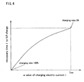
Fig.4 is a graph showing a relation of a necessary time for fully charging a
secondary battery 1 to electric current flowing therethrough.
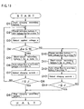
Fig.5 is a flow chart of charging control of a secondary battery 1 by a
charging equipment according to a first embodiment of the present invention.
Fig.6 is a circuit diagram for switching voltage applied to a secondary
battery 1 according to the first embodiment.
Fig.7 is a time chart showing timings of switching voltage applied to a
secondary battery 1 according to the first embodiment.
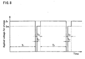
Fig.8 is a time chart showing variation of voltage applied to a secondary
battery 1 in association with switching voltage applied to the secondary
battery 1 according to the first embodiment.
Fig.9 is a time chart about the battery terminal voltage, the charging
electric current, and the check electric current of a nickel-hydrogen battery.
Fig.10 is a time chart about the battery terminal voltage, the charging
electric current, and the check electric current of a nickel-cadmium battery.
Fig.11 is a flow chart of charging control of a secondary battery 1 by a
charging equipment according to a second embodiment of the present
invention.
Fig.12 is a flow chart of charging control of a secondary battery 1 by the
charging equipment according to the second embodiment.
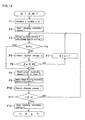
Fig.13 is a flow chart of charging control of a secondary battery 1 by the
charging equipment according to the third embodiment.
Fig.14 is a flow chart of charging control of a secondary battery 1 by the
charging equipment according to the third embodiment.
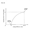
Fig.15 is a graph showing a relation of voltage difference ΔEs, which equals
special charging voltage Es minus open-circuit voltage Ex of a secondary
battery 1, to the necessary time for fully charging.
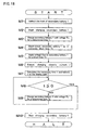
Fig.16 is a flow chart of charging control of a secondary battery 1 by a
charging equipment according to a fourth embodiment of the present
invention.
Fig.17 is a flow chart of charging control of a secondary battery 1 by a
charging equipment according to a fifth embodiment of the present invention.
Fig.18 is a flow chart of charging control of a secondary battery 1 by a
charging equipment according to a sixth embodiment of the present invention.
Fig.19 is a flow chart of charging control of a secondary battery 1 by a
charging equipment according to a seventh embodiment of the present
invention.
Fig.20 is a block diagram of a charging equipment for a secondary battery 1
according to an eighth embodiment or a ninth embodiment of the present
invention.
Fig.21 is a flow chart of charging control of a secondary battery 1 by the
charging equipment according to the eighth embodiment.
Fig.22 is a flow chart of charging control of a secondary battery 1 by the
charging equipment according to the ninth embodiment.
Fig.23 is a basic circuit diagram of the charging equipment according to the
eighth embodiment or the ninth embodiment.
Fig.24 is a block diagram of the charging equipment for a plurality of
secondary batteries 1 according to a tenth embodiment or an eleventh
embodiment of the present invention.
Fig.25 is a flow chart of charging control of a plurality of secondary
batteries 1 by the charging equipment according to the tenth embodiment.
Fig.26 is a flow chart of charging control of a plurality of secondary
batteries 1 by the charging equipment according to the eleventh embodiment.
Fig.27 is a block diagram of a charging equipment for a plurality of
secondary batteries 1 according to a twelfth embodiment of the present
invention.
Fig.28 is a flow chart of charging control of a plurality of secondary
batteries 1 by the charging equipment according to the twelfth embodiment.
Fig.29 is a plan view of a charging equipment for a plurality of secondary
batteries 1 according to a fourteenth embodiment of the present invention.
Fig.30 is a sectional side view of a charging equipment for a plurality of
secondary batteries 1 according to a fifteenth embodiment of the present
invention.
Fig.31 is a sectional rear view of take-off means of a charging equipment
for a plurality of secondary batteries 1 according to a sixteenth embodiment of
the present invention.
Fig.32 is a sectional side view of take-off means of a charging equipment
for a plurality of secondary batteries 1 according to a seventeenth embodiment
of the present invention.
Best Mode for Carrying out the Invention
A charging method by the charging equipment for a secondary battery in the
present invention explained below is characterized in that high electric
current is supplied to a secondary battery by applying the highest voltage (a
predetermined charging voltage) out of a region of charging voltage causing
irreversible chemical reaction in the secondary battery so as not to damage the
internal structure of the secondary battery, and that the secondary battery is
periodically checked whether the secondary battery is fully charged or not
(whether charge of the secondary battery is finished or not). For this check,
equilibrium charging voltage for equilibrium cell potential of the secondary
battery in a fully charged condition is applied to facilitate quick and accurate
judge whether the secondary battery precisely is fully charged or not. By
this charging method, the time for fully charging a secondary battery can be
reduced to thirty minutes or less. Furthermore, by the method, electricity
can be appropriately charged to the secondary battery appropriately without
causing excessive damaging chemical reaction (oxidation-reduction reaction)
in the secondary battery till the secondary battery is fully charged, thereby
increasing effective battery cycles of the secondary battery to five thousands
times or more.
First of all, a fundamental composition of a charging equipment for a
secondary battery according to the present invention will be explained
referring to Fig.1.
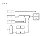
The charging equipment shown in Fig.1 is provided for charging a
secondary battery 1. The charging equipment comprises a power supply part
2, a current detection part 3, a voltage detection part 9, and a control part 4
for programming and calculating. The power supply part 2 includes a
transformer-rectifier circuit for changing commercial alternating current into
direct current. The current detection part 3 detects a value of charting
electric current flowing through the secondary battery 1. The voltage
detection part 9 detects a value of voltage applied in the secondary battery 1,
or a value of charging voltage supplied to the secondary battery 1. The
control part 4 is charge control means for controlling charge of the secondary
battery 1. The value of electric current detected by the current detection part
3 and the value of voltage detected by the voltage detection part 9 are
transmitted to the control part 4.
The control part 4 serving as the charge control means comprises a storage
means (memory), which previously stores two values of charging voltage:
equilibrium voltage Eeq provided for equilibrium cell voltage of the secondary
battery 1 in a fully charged condition (see Fig.3) and special voltage Es larger
than the equilibrium voltage Eeq (as showing Fig.3, the special charging
voltage Es corresponds to the peak value of electric current Iso which is
reached when charging current is not increased any more. When the
secondary battery 1 whose charging rate is almost 0% is charged, the
increasing rate of charging current to increasing applied voltage (ΔI/ΔE) is
decreased just before the charging current reaches the peak value. The
special charging voltage Es relative to electric current does not reach a region
thereof causing irreversible chemical reaction (an irreversible chemical
reaction D).
The control part 4 also stores several programs such as a judging program
for judging whether the secondary battery 1 is fully charged or not, and a
charge time predicting program for estimating necessary time t to fully charge
the secondary battery.
A reference numeral 5 in Fig.1 designates a voltage/electric current control
part, which controls change of voltage and electric current flowing through
the secondary battery 1 according to a command from the control part 4. In
other words, the voltage/electric current control part 5 comprises a switching
means for switching charging voltage between the equilibrium voltage Eeq and
the special voltage Es.
A reference numeral 6 designates a charging voltage supply part, which
supplies the charging voltage set by the voltage/electric current control part 5
according to a starting command, and finishes charging according to an ending
command from the control part 4. A reference numeral 7 designates a
display part for displaying a necessary time t to fully charge the secondary
battery 1, and others, which are calculated in the control part 4. A reference
numeral 8 designates an operation part, which is operated by a user for
starting and the like.
As for the following embodiments, the charging equipment comprises the
display part 7 as a visual monitor for indicating the necessary time t to fully
charge the secondary battery 1 and others to a user. However, instead of the
visual type display part 7, the charging equipment may have any type monitor
device using sound etc.
A herein-said secondary battery means a rechargeable battery, which can
repeat charge-discharge cycles. In the charging process, electrical energy is
transformed into chemical potential energy, which is stored in the secondary
battery. The stored chemical potential energy is converted back into
electrical energy when the need arises.
Typical and practical batteries serving as the secondary battery 1 are a
nickel-cadmium battery, a nickel metal hydride battery, a lithium ion battery,
a NAS battery, and the like.
A nickel-cadmium battery serving as the secondary battery 1 charged by the
charging equipment of each embodiment will now be explained.
A nickel-cadmium battery is a storage battery which comprises a
hermetically sealed cell container filled with alkali electrolyte, a separator
made of synthetic resins for separating the cell container into two rooms, a
positive electrode made of nickel oxyhydroxide (Ni(OOH)) in one room, and a
negative electrode made of cadmium (Cd) in the other room.
The electrolyte is an aqueous solution whose main ingredient is potassium
hydroxide with high electric conductivity. If needed, lithium hydroxide,
sodium hydroxide, etc. may be added to this aqueous solution in order to raise
the capacity of the positive electrode.
In electromotive reaction of the nickel-cadmium battery, the chemical
reaction on the positive electrode is expressed by the following formula.
2Ni(OOH)+H2O+2e- ⇄ 2Ni(OH)2+2OH-
The chemical reaction on the negative electrode is expressed by the
following formula.
Cd+2OH- ⇄ Cd(OH)2+2e-
In its discharging process, oxyhydroxide (Ni(OOH)) reacts with water
(H2O) and electron (e-) from the positive electrode to form hydroxylation
nickel (Ni(OH)2) on the positive electrode.
On the other hand, cadmium (Cd) reacts with hydroxylation ion (OH-)
generated from the positive electrode and entering the negative electrode
room through the separator to form hydroxylation cadmium (Cd(OH)2) and
electron (e-) on the negative electrode. This electron (e-) passes through
external load and is supplied to the positive electrode.
In this cycle, the electron (e-) passing through the external load is used for
work. Therefore, this cycle requires the following conditions for its smooth
performance: Plenty of water (H2O) involving hydroxylation nickel
(Ni(OH)2) as production in low concentration exists around the positive
electrode, and hydroxylation cadmium (Cd(OH)2) in low concentration around
the negative electrode. This relation can be expressed by the following
formula.
Eemf=E0+((R*T)/F)*ln(Caq/(CN*CC))
E0 is standard electromotive force. E0 is a constant decided according to
materials of the positive and negative electrodes regardless of quantity of the
substances. For example, the standard electromotive force E0 of the
nickel-cadmium battery is about 1.2V(volt). R is the gas constant, T is
absolute temperature, and F is Faraday constant.
The above-mentioned formula shows that, at the positive electrode, the
higher the concentration (Caq) of water (H2O) is and the lower the
concentration (CN) of hydroxylation nickel (Ni(OH)2) is, the larger the
Electromotive force Eemf becomes, and at the negative electrode, the lower the
concentration (CC) of hydroxylation cadmium (Cd(OH)2) is, the larger the
electromotive force Eemf becomes. It means that the larger the electromotive
force Eemf is, the larger the capacity of accumulation of electricity in the
secondary battery becomes.
Incidentally, a circuit shown in Fig.2 may be made so as to know the
charged condition of the secondary battery 1 exactly. In the circuit, a
variable power supply 11 is connected to the secondary battery 1, and an
electrical potential of the variable power supply 11 is adjusted to a potential
equaling the electromotive force E of the secondary battery 1. That is, the
variable power supply 11 is adjusted so that a value of the electric current
detected by the current detection part 3 may be set to ±0mA, whereby the
electromotive force Eemf of the secondary battery 1 is measured indirectly.
In this way, for charging various types of secondary batteries 1, the
electromotive force Eemf of each of the secondary batteries 1 in their fully
charged condition is previously inputted into the control part 4 serving as the
storage means.
Next, referring to the graph of Fig.3, a characteristic of relation between
voltage and current for charging the secondary battery 1 will be explained,
which is a fundamental theory underling hereinafter description of the present
charging method.
Fig. 3 shows voltage-current characteristic curves in a charged secondary
battery 1 corresponding to different charging rates, with battery terminal
voltage (applied voltage) as the abscissa, and charging current as the y-axis.
A graph α drawn in a dashed line expresses a voltage-current characteristic
during charge of the secondary battery 1 when its charging rate is
approximately 0%. In this case, even if the voltage Eα lower than the
standard voltage (nominal voltage) E0 is applied, electric current starts
flowing to be charged. (The applied voltage (battery terminal voltage) when
electric current begins flowing to be charged is defined as open-circuit
voltage.)
The larger the charging rate is, the higher the open-circuit voltage becomes.
A graph β drawn with a long dashed short dashed line in Fig.3 expresses a
voltage-current characteristic during charge of the secondary battery 1 when
its charging rate is approximately 50%. Open-circuit voltage Eβ for starting
flow of electric current to be charged is applied higher than the open-circuit
voltage Eα for charging the secondary battery 1 when its charging rate is
approximately 0%. A graph γ drawn in a long dashed double-short dashed
line in Fig.3 expresses a voltage-current characteristic during charge of the
secondary battery 1 when its charging rate is approximately 90%, requiring
open-circuit voltage Eγ higher than Eβ. A graph δ drawn in a continuous line
in Fig.3 expresses a voltage-current characteristic during charge of the
secondary battery 1 when its charging rate is approximately (less than) 100%,
requiring open-circuit voltage Eδ higher than Eγ. Open-circuit voltage for
the secondary battery 1 when its charging rate is just 100% is equal to the
equilibrium voltage Eeq which is higher than Eδ.
Electric current charged in the secondary battery 1 is increased
substantially in proportion to increase of applied voltage higher than
open-circuit voltage Ex (Eα, Eβ, Eγ, Eδ etc.) corresponding to its initial
charging rate. When the applied voltage passes over a certain voltage (an
inflection point of the voltage-current curve), the increase rate of charging
electric current to applied voltage (ΔI/ΔE) begins to decrease. Finally,
charging electric current reaches peak electric current Iso and does not
increase any more even if applied voltage is increased.
Applied voltage corresponding to the peak electric current Iso, which is
charging electric current when the increase rate of charging electric current to
applied voltage (ΔI/ΔE) becomes zero, is the special voltage Es peculiar to
each secondary battery 1, determined by a kind, a degraded state, and other
element of the secondary battery 1 to be charged.
If voltage higher than the special voltage Es is applied to the secondary
battery 1, oxidation-reduction reaction of active substance is further promoted
so as to cause electrolysis reaction in the secondary battery 1, whereby the
characteristic of negative resistance appears. In the worst case, the internal
structure of the secondary battery 1 may be destroyed by unexpected
abnormalities such as exothermic reaction and swelling reaction. Even if
such the worst case does not happen, applied voltage higher than the special
voltage Es promotes irreversible chemical reaction leading to reduction of
effective battery cycles of the secondary battery 1. The irreversible
chemical reaction region D hatched in Fig. 3 is a region of the relationship
between charging electric current and applied voltage such as to cause
irreversible chemical reaction which is harmful to the secondary battery 1.
The graph α corresponding to the secondary battery 1 when its charging rate
is approximately 0% shows that the charged peak electric current Iso is still
kept in spite of increasing applied voltage in the region D. Each of the
graphs β, γ and δ shows that, in the region D, as applied voltage is increased,
charging electric current is decreased and the decreasing rate of charging
electric current is increased. Finally, the characteristic of negative
resistance of the secondary battery 1 in the region D, which appears as the
irreversible chemical reaction, is turned as the bulk specific resistance
increasing in proportion to the rise of applied voltage.
Therefore, it is necessary for charging a secondary battery 1 to control
voltage applied to the secondary battery 1 lest the charging electric current
relative to applied voltage should enter the irreversible chemical reaction
region D before the secondary battery 1 is fully charged (the state of its
charging rate 100%).
Incidentally, Fig.3 shows that the minimum voltage in the irreversible
chemical reaction region D (on the border of the reaction region D) becomes
smaller according to increase of charging rate (or decrease of charging
electric current). The capacity of accumulation of electricity in the
secondary battery 1 is product of charging electric current multiplied by
charge time. Therefore, for shortening the charge time, it is necessary to
increase charging electric current. Under the constant charging rate, the
higher applied voltage is, the larger charging electric current becomes.
The requirement for charging a secondary battery 1 is to prevent the
relationship between charging electric current and applied voltage from
entering the region D in spite of increase of charging rate till the secondary
battery 1 is fully charged, and to flow the maximum electric current in the
secondary battery when its charging rate is approximately 0%. Taking the
requirement into account, the open-circuit voltage Eeq for the fully charged
secondary battery 1, shown in Fig. 3, is worthy of application to the secondary
battery 1. The voltage Eeq is used as the equilibrium voltage provided for
equilibrium cell potential of the secondary battery 1 in its fully charged
condition.
The application of equilibrium voltage Eeq facilitates easy judgment
whether the secondary battery 1 is fully charged or not, because the higher
charging rate is, the lower charging electric current becomes.
This merit will be explained referring to the Fig.3. When the equilibrium
voltage Eeq is constantly applied to the terminals of the secondary battery 1
whose initial charging rate is approximately 0%, charging electric current Ieqo
(see the graph α) flows through the secondary battery 1 at first. The higher
its charging rate rises according to the progress of charge, the lower charging
electric current falls from the electric current Ieqo (see the graphs β and γ).
The relative value of the charging electric current to the applied voltage does
not enter the irreversible chemical reaction region D until the secondary
battery 1 is fully charged (its charging rate reaches 100%). The charging
electric current becomes 0mA when the secondary battery 1 is fully charged.
Thus, whether the secondary battery 1 is fully charged or not can be easily
judged.
However, the secondary battery 1 has the potential for receiving the peak
electric current Iso higher than the electric current Ieqo without causing
irreversible chemical reaction in the secondary battery 1, while the special
charging voltage Es in spite of any charging rate of the secondary battery 1
(whether charging rate of the secondary battery 1 is approximately 0% or
100%). Such high charging electric current flowing through the secondary
battery 1 can remarkably reduce charge time in comparison with the charge
time when the secondary battery 1 is charged by application of the equilibrium
voltage Eeq.
Therefore, according to the present embodiment, the secondary battery 1 is
charged by constantly applying the special charging voltage Es for a
considerable time so as to flow the maximum charging electric current (the
peak electric current Iso) out of the irreversible chemical reaction region D,
and by switching applied voltage from the special charging voltage Es to the
equilibrium voltage Eeq at a suitable time so as to reduce charging electric
current. Whether the secondary battery 1 is fully charged or not is judged
during the application of the equilibrium voltage Eeq to the secondary battery
1.
While the special charging voltage is applied to the secondary battery 1 so
as to increase the charging rate thereof, almost the peak electric current Iso is
kept as charging electric current, thereby increasing the charging rate for a
greatly short time. By applying the equilibrium voltage Eeq to the secondary
battery 1 for a suitable time, charging electric current becomes lower
according to increase of charging rate of the secondary battery 1, thereby
preventing the secondary battery 1 from overcharging and facilitating easy
judgment whether the secondary battery 1 is fully charged or not.
Voltage to be applied for charging the secondary battery 1 with large
electric current is not limited to the special charging voltage Es corresponding
to the peak electric current Iso. It may be lower than the voltage Es so as to
correspond to electric current smaller than the peak electric current Iso. In
other words, as shown in Fig.3, the voltage to be applied is set to a value
corresponding to a selective value of electric current, out of the irreversible
chemical reaction region D, which extremely approaches but does not reach
the peak current. The selective value of electric current is pointed on the
current-voltage graph where the increasing rate of charging electric current to
applied voltage (ΔI/ΔE) reduces. By applying this voltage, the secondary
battery 1 can be also charged with high electric current, which is almost the
peak electric current Iso.
To provide the peak electric current Iso, which is kept constant regardless of
variation of charging rate, for charging the secondary battery 1, the special
charging voltage Es corresponding to the kind of secondary battery 1 to be
charged may be established basing on the graph α in Fig.3, for example, i.e.,
the current-voltage characteristic of the secondary battery 1 whose charging
rate is almost 0%, wherein the peak electric current Iso is kept in a certain
variation area of applied voltage. In other words, the special charging
voltage Es is set to voltage just before reaching the irreversible chemical
reaction region D, which is defined on the graph as a point where the
increasing rate of charging electric current according to the rise of applied
voltage (ΔI/ΔE) is decreased to 0 or almost 0.
(First Embodiment of Charging Equipment for Secondary Battery)
A charging equipment for a secondary battery 1 according to the first
embodiment will be explained.
This charging equipment uses the method comprising the step of: switching
charge with high electric current to charge with application of the equilibrium
voltage at a suitable time, and judging basing on the detected value of electric
current which is suitable, charge with high electric current or charge with
application of the equilibrium voltage.
Fig.1 shows composition of the charging equipment of the first embodiment.
The control part 4 has a check current judging program for judging whether
check current i detected by the current detection part 3 during application of
the equilibrium voltage Eeq to the secondary battery 1 is larger than a preset
standard electric current J for finishing charging or not, a charge time
predicting program for estimating necessary time t to fully charge the
secondary battery 1 basing on the value of check current i detected by the
current detection part 3 during application of the equilibrium voltage Eeq. In
short, the control part 4 functions as both of a check current judging means
and a charge time predicting means.
The charging equipment of the first embodiment is controlled by this
control part 4 as follows. The charging equipment applies the special
charging voltage Es (or voltage considerably smaller than the special charging
voltage Es) to the secondary battery 1 for a determined time T1. After charge
with high electric current during the application of the special charging
voltage Es, the charging equipment switches voltage applied to the secondary
battery 1 from the special charging voltage Es to the equilibrium voltage Eeq,
and detects a value of electric current i flowing through the secondary battery
1 during the application of the equilibrium voltage Eeq to the secondary
battery 1. Basing on the detected value of electric current i, the charging
equipment predicts necessary time t to fully charge the secondary battery 1
and displays necessary time t on the display part 7 with LED, LCD or the like,
and simultaneously, the charging equipment judges whether the detected value
of electric current i is larger than the preset standard value of electric current
J for finishing charging or not. If the detected value of electric current i is
larger than the standard value of electric current J for finishing charging, the
charging equipment applies the special charging voltage Es to the secondary
battery 1 again; otherwise, charge of the secondary battery 1 is halted.
Incidentally, the necessary time t to fully charge the secondary battery 1
can be predicted from the graph in Fig.4, for example, which illustrates the
relation between electric current i and the necessary time t.
The graph in Fig.4 shows the relation between the detected value of electric
current i during application of the equilibrium voltage Eeq and the necessary
time t till the secondary battery 1 is fully charged. The necessary time t is a
time required by electric current i detected by the current detection part 3 to
reach the standard value of electric current J for finishing charging, e.g.,
0mA.
Referring to Fig.3, electric current Ieqo is detected as a value of electric
current i during application of the equilibrium voltage Eeq to the secondary
battery 1 whose charging rate is 0%. The graph in Fig.4 shows that, as the
charging rate is increased, the necessary time t and the detected electric
current i are decreased. In this graph, when the detected value of electric
current i reaches 0mA, the secondary battery 1 is recognized to be fully
charged so that the charging rate becomes 100% and the necessary time t is 0
second.
Accordingly, if a conversion table for converting the check current i into
the necessary time t to fully charge the secondary battery 1 formed basing on
this graph, or a relational expression which formulates the relation between
the check current i and the necessary time t to fully charge the secondary
battery 1 basing on the graph is made as the charge time predicting program,
the necessary time t to fully charge the secondary battery 1 can be estimated
basing on the detected value of electric current i.
Next, the control flow of charging the secondary battery 1 by the charging
equipment of the first embodiment will be explained referring to a fl ow chart
shown in Fig.5.
First of all, a user inputs a kind of secondary battery 1 to be charged to the
control part 4 by manipulating the operation part 8, thereby selecting the
special charging voltage Es and equilibrium voltage Eeq in correspondence to
the kind of secondary battery 1 from a table in the storage means in the
control part 4 [step A1].
Both the special charging voltage Es and the equilibrium voltage Eeq are
determined by the kind or type of secondary battery 1, such as the
nickel-cadmium battery, the nickel metal hydride battery, and the lithium ion
battery. For example, with regard to the nickel-cadmium battery, the
equilibrium voltage Eeq is set to around 1.41V, and the special charging
voltage Es is set to around 1.81V higher than the equilibrium voltage Eeq.
A user manipulates the operation part 8 to start charging [step A2], whereby
the charging equipment applies the selected special charging voltage Es to the
secondary battery 1 for a predetermined time (a fixed time) T1 [step A3].
The predetermined time T1 is calculated basing on variation of charging
electric current according to the time progress during the application of
special charging voltage Es. After the predetermined time T1 passes, the
charging equipment short-circuits the secondary battery 1 between its
terminals for an extremely short time T2 [step A4], so as to remove electric
charge from the electrode interface of the secondary battery 1. Then, the
charging equipment switches applied voltage to the equilibrium voltage Eeq
[step A5].
The charging equipment detects a value of electric current i flowing
through the secondary battery 1 during the application of equilibrium voltage
Eeq to the secondary battery 1 of short duration [step A6].
Next, the charge time predicting program calculates the necessary time t to
fully charge the secondary battery 1 basing on the detected electric current i,
that is, the time t required for the detected electric current i to reach the
standard electric current J for finishing charging (the value of electric current
which will be detected at the fully charged condition), and this necessary time
t is indicated on the display part 7 [step A7].
At the same time, the check current judging program compares the detected
electric current i with the standard electric current J for finishing charging
[step A8]. If the detected electric current i is larger than the standard
electric current J for finishing charging, the control step returns to the step A3,
and the above steps (charge control) are repeated. Otherwise, the charging
equipment recognizes that the secondary battery 1 is fully charged, and it
stops charging the secondary battery 1 [step A9].
Incidentally, if equilibrium voltage Eeq is applied and the charging rate is
100% (the secondary battery 1 is fully charged), electric current i
theoretically becomes 0mA, as shown in the graphs in Fig.3 and Fig.4.
However, the fact is that the electric current are slightly different among
different secondary batteries of the same type. Therefore, the standard
electric current J for finishing charging to the value is desired to be slightly
more than 0mA, such as 10mA, for preventing the secondary battery 1 from
overcharging. In this case, the necessary time t to fully charge is a time
required for the detected electric current i to reach a value not more than
10mA.
The charging time T1 for applying the special charging voltage Es varies
depending on the battery's capacity, structure, form, or the like. For
example, with regard to the nickel-cadmium battery, the charging time T1 is
set to around 120 seconds. The extremely short time T2 for short-c ircuiting
the terminals of the secondary battery 1 is a time required to clear the electric
charge from the electrode interface of the secondary battery 1. With regard
to the nickel-cadmium battery, the extremely short time T2 is set to around
0.001 second. Furthermore the short time T3 for applying the equilibrium
voltage Eeq is set to around 0.1 second.
If the short time T3 is set to more than 1 second, the above-mentioned step
A4 may be omitted.
To change charging voltage, shown in the flow chart of Fig.5, the circuit
shown in Fig.6 may be used, for example. Referring to Fig.1, a reference
numeral 1 designates a secondary battery, a reference numeral 3 designates a
current detection part 3 for detecting charging electric current flowing
through the secondary battery 1, and a reference numeral 9 designates a
voltage detection part 9 for detecting voltage applied to the secondary battery
1. This circuit has a first gate 36, a second gate 37, and a third gate 38 for
switching elements such as field-effect transistor (FET). A reference
numeral 31 designates a first power supply (variable power supply) that can
change the setting of equilibrium voltage Eeq suitable for a kind or a type of
the secondary battery 1 to be charged, and a reference numeral 32 designates a
second power supply for applying the special charging voltage Es.
For further details, the plus terminal of the secondary battery 1 is connected
to the emitter of the first gate 36, the emitter of the second gate 37, the
collector of the third gate 38, and the minus terminal of the voltage detection
part 9, respectively. The collector of the first gate 36 is connected to the
plus terminal of the second power supply 32, and the minus terminal of the
second power supply 32 is connected to both the plus terminal of the first
power supply 31 and the collector of the second gate 37. The minus terminal
of the first power supply 31 is connected to the plus terminal of the current
detection part 3. The minus terminal of the current detection part 3 is
connected to the plus terminal of the voltage detection part 9, the minus
terminal of the secondary battery 1, and the emitter of the third gate 38.
Next, the method for controlling applying voltage to the secondary battery
1 using the circuit in Fig.6 will be explained referring to Fig.7 and Fig.8.
First of all, only the first gate 36 is switched on so as to apply the special
charging voltage Es to the secondary battery 1 for a determined time T1.
After the passage of the determined time T1, the first gate 36 is switched off
and only the third gate 38 is switched on so as to short-circuit the terminals of
the secondary battery 1 for an extremely short time T2. In this way, the gates
36, 37 and 38 constitute means for short-circuiting the secondary battery 1
between its terminals. By the short-circuiting, electric charge is removed
from the electrode interface of the secondary battery 1 so as to enable voltage
to be smoothly applied to the secondary battery 1 at the next step, and to
stabilize electric current flowing through the secondary battery 1 immediately
after change of charging voltage, thereby ensuring accurate detection of
electric current.
After the passage of the extremely short time T2, the third gate 38 is
switched off and the second gate 37 is switched on so as to apply the
equilibrium voltage Eeq for checking the charged condition of the secondary
battery 1 for a short time T3. During the short time T3, the current detection
part 3 detects a value of electric current i flowing through the secondary
battery 1. Basing on the detected electric current i, the check current
judging program judges whether the secondary battery 1 is fully charged or
not, and the charge time predicting program calculates the necessary time t to
fully charge the secondary battery 1. After the short time T3 passes, the
second gate 37 is switched off.
If the check current judging program judges that the secondary battery 1 is
not fully charged, the first gate 36 is switched on so as to apply the special
charging voltage Es for charging the secondary battery 1, and
above-mentioned control steps are repeated.
On the other hand, if the check current judging program judges that the
secondary battery 1 is fully charged, charge of the secondary battery 1 is
halted.
According to the charging equipment of the first embodiment, a value of
electric current i is detected so as to check the charged condition of the
secondary battery 1 periodically, thereby appropriately charging the
secondary battery 1 without causing excessive damaging chemical reaction
(oxidation-reduction reaction) in the secondary battery 1 till the secondary
battery 1 is fully charged. The internal structure of the secondary battery 1
is prevented from being damaged so as to remarkably increase effective
battery cycles of the secondary battery 1. Moreover, by this charging method
with the charging equipment of the first embodiment, the special charging
voltage Es larger than the equilibrium voltage Eeq is mainly applied so as to
make considerably high charging electric current flow through the secondary
battery 1, thereby reducing charging time.
Moreover, the charging equipment of the first embodiment estimates
necessary time t to fully charge the secondary battery 1 basing on the detected
electric current i, and displays the necessary time t on the display part 7,
thereby improving users' convenience for monitoring the time required to
fully charge the secondary battery 1.
Furthermore, the charging equipment of the first embodiment short-circuits
the terminals of the secondary battery 1 before it switches voltage applied to
the secondary battery 1 from the special charging voltage Es to the
equilibrium voltage Eeq. By the short-circuiting, electric charge is cleared
from the electrode interface of the secondary battery 1 so as to enable voltage
applied to the secondary battery 1 to be smoothly switched to the equilibrium
voltage Eeq, thereby stabilizing electric current flowing through the secondary
battery 1 immediately after the change of voltage to the equilibrium voltage
Eeq. Consequently, the charging equipment can detect electric current i
accurately, and charge the secondary battery 1 appropriately.
(Second Embodiment of Charging Equipment for Secondary Battery)
Next, a charging equipment for a secondary battery 1 according to the
second embodiment of the present invention will be explained.
The charging equipment of the second embodiment is characterized in that
it can identify the kind of secondary battery 1 automatically in the process of
charge without inputting data of the kind of secondary battery 1 so as to
charge the secondary battery 1 rapidly till it is fully charged. The "kind" of
secondary battery 1 means not only classification of the secondary batteries
by the difference in substance of the plus terminal and/or the minus terminal
such as a nickel-cadmium battery and a nickel-hydrogen battery, but also
classification of the secondary battery having the same plus terminal and the
same minus terminal by the difference in charge capacity.
The equilibrium voltage Eeq and the special charging voltage Es are
determined by the sort and the charge capacity of the secondary battery.
For example, regarding a nickel-cadmium battery whose charge capacity is
1000mAh(milliampere-hour), the equilibrium voltage is about 1.41V, and the
special charging voltage is about 1.80V. Regarding a nickel-hydrogen
battery whose charge capacity is 2000mAh, the equilibrium voltage is about
1.44V, and the special charging voltage is about 1.60V.
Fig.9 is a time chart showing a time progress of the battery terminal voltage,
a time progress of charging electric current, and check electric current when a
nickel-hydrogen battery is charged by the charging equipment of the first
embodiment under the condition that the equilibrium voltage is set to 1.44V
and the special charging voltage is set to 1.60V, corresponding to the
nickel-hydrogen battery. Fig.10 is a time chart showing a time progress of
the battery terminal voltage, a time progress of charging electric current, and
check electric current when a nickel-cadmium battery is charged by the
charging equipment of the first embodiment under the condition that the
equilibrium voltage is set to 1.44V and the special charging voltage is set to
1.60V, corresponding to the nickel-hydrogen battery. In both Fig.9 and
Fig.10, the determined time T1 for applying the special charging voltage
1.60V at the above-mentioned step A3 is set to 55 seconds, the process of
short circuit at the step A4 is omitted, and the short time T3 for applying the
equilibrium voltage 1.44V at the step A5 is set to 5 seconds.
Between the power supply part 2 and the charging voltage supply part 6
through the voltage/electric current control part 5, shown in Fig.1, some
resistance occurs so as to cause voltage drop. When corresponding to the
nickel-hydrogen battery, the charging equipment is designed so that voltage of
2.0V from the power supply part 2 drops while passing the voltage/electric
current control part 5 and the charging voltage supply part 6 so as to set the
voltage applied between the terminals of the nickel-hydrogen battery to about
1.6V.
As shown in Fig.3, while applying special charging voltage Es to the
secondary battery 1, constant charging electric current (that is the peak
electric current Iso) flows through the secondary battery 1 regardless of
variation of its charging rate. If voltage lower than the special charging
voltage Es is applied to the secondary battery 1, charging electric current
flowing through the secondary battery 1 is decreased according to increase of
the charging rate.
According to such characteristics, as shown in Fig.9, when a
nickel-hydrogen battery is charged with the setting voltage matching with the
nickel-hydrogen battery, the voltage applied between the terminals of the
nickel-hydrogen battery is about 1.6V corresponding to the special charging
voltage (1.60V) of the nickel-hydrogen battery, and the constant electric
current (the peak value of electric current Iso) corresponding to the special
charging voltage flows through the nickel-hydrogen battery, whereby the
voltage drop between the power supply part 2 and the charging voltage supply
part 6 through the voltage/electric current control part 5 is kept almost
constant. That is to say, almost constant voltage without exceeding 1.6V is
applied between the terminals of the nickel-hydrogen battery and almost
constant charging electric current flows therethrough while charging from the
beginning of charge to the end of charge. The charging electric current
flowing through the nickel-hydrogen battery can be checked appropriately by
periodically applying the suitable equilibrium voltage 1.44V to the
nickel-hydrogen battery, thereby charging the nickel-hydrogen battery rapidly
and accurately till the fully charged condition.
As shown in Fig.10, when a nickel-cadmium battery is charged with setting
of voltage corresponding to the nickel-hydrogen battery, the voltage applied
between the terminals of the nickel-cadmium battery varies between 1.4V and
1.6V for a while after starting charging.
This applied voltage is lower than the special charging voltage (1.80V) of
the nickel-cadmium battery so that as its charging rate goes up, charging
electric current flowing through it decreases gradually. With the diminution
of charging electric current, voltage drop generated between the power supply
part 2 and the charging voltage supply part 6 through the voltage/electric
current control part 5 becomes smaller by degrees, so that the voltage applied
between the terminals of the nickel-cadmium battery becomes larger by
degrees. Finally, the voltage exceeds 1.6V and reaches about 1.8V at the end
of charge.
The charging electric current flowing through the nickel-cadmium battery is
checked by periodically applying the suitable equilibrium voltage 1.44V to
the nickel-cadmium battery. However, the equilibrium voltage 1.44V
corresponding to the nickel-hydrogen battery is higher than the equilibrium
voltage 1.41 V corresponding to the nickel-cadmium battery, so that the
nickel-cadmium battery cannot be exactly charged till the fully charged
condition.
To solve this problem, the charging equipment of the second embodiment
distinguishes a type of secondary battery to be charged between a
nickel-cadmium battery and a nickel-hydrogen battery, for example. The
charging equipment applies voltage corresponding to the nickel-cadmium
battery for charging a secondary battery 1 and for checking its charging rate.
If the charging voltage applied between the terminals of the secondary battery
1 exceeds 1.6V, the secondary battery 1 is judged to be a nickel-cadmium
battery. Afterward, the charging equipment applies voltage corresponding to
the nickel-cadmium battery for charging the secondary battery 1 and for
checking its charging rate.
The charging equipment of the second embodiment will be detailed. This
is constructed similarly with that of Fig.1. The storage means (memory) in
the control part 4 stores equilibrium voltages Eeq and special charging
voltages Es corresponding to respective kinds of secondary batteries. The
control part 4 has a check current judging program and a voltage judging
program. The check current judging program serves as means for judging
whether electric current i detected by the current detection part 3 during
application of the equilibrium voltage Eeq is larger than preset standard
electric current J for finishing charging or not. The voltage judging program
serves as means for judging whether voltage e detected by the voltage
detection part 9 during application of the special charging voltage Es is larger
than the special charging voltage Es or not.
Explanation of other parts in the charging equipment of the second
embodiment is omitted because they are almost similar with those of the first
embodiment.
The control flow of charging the secondary battery 1 by the charging
equipment of the second embodiment, wherein the storage means in the
control part 4 stores two values of equilibrium voltage Eeq (Eeq1, Eeqh) and two
values of special charging voltage Es (Es1, Esh) corresponding to two kinds of
secondary batteries, referring to the flow chart shown in Fig.11.
The equilibrium voltage Eeq1 is lower than the equilibrium voltage Eeqh and
the special charging voltage Es1 is lower than the special charging voltage Esh.
First of all, a user manipulates the operation part 8 of the charging
equipment to start charging [step B1]. Accordingly, the charging equipment
applies the lower special charging voltage Es1 to the secondary battery 1 for a
determined time (a fixed time) T1 [step B2].
While the determined time T1 of application of the lower special charging
voltage Es) to the secondary battery1, the voltage detection part 9 detects
voltage e applied to the secondary battery 1 [step B3], and the voltage judging
program judges basing on the detected value of voltage e [step B4]. If the
detected voltage e is higher than the lower special charging voltage Es1, the
control step jumps to the later mentioned step B10. Otherwise, the control
step goes to the next step B5.
After the determined time T1 passes, the charging equipment short-circuits
the secondary battery 1 between its terminals for an extremely short time T2
[step B5] so as to remove electric charge from the electrode interface of the
secondary battery 1. Then, the charging equipment switches applied voltage
from the lower special charging voltage Es1 to the lower equilibrium voltage
Eeq1, and applies the lower equilibrium voltage Eeq1 to the secondary battery 1
for a short time T3 [step B6].
If the short time T3 is set to more than 1 second, the above-mentioned step
B5 may be omitted.
The charging equipment detects a value of electric current i flowing
through the secondary battery 1 during the application of the lower
equilibrium voltage Eeq1 to the secondary battery 1 for a short time T3 [step
B7].
Then, the check current judging program judges basing on the detected
value of electric current i [step B8]. If the detected electric current i is
larger than the standard electric current J for finishing charging, the control
step returns to the step B2, and the above steps are repeated. Otherwise, the
charging equipment stops charging the secondary battery 1 [step B9].
At the above mentioned step B4, if the voltage e detected by the voltage
detection part 9 is larger than the lower special charging voltage Es1, the
charging equipment switches applied voltage from the lower special charging
voltage Es1 to the higher special charging voltage Esh, and applies the higher
special charging voltage Esh to the secondary battery 1 for a determined time
T1 [step B10].
After the determined time T1 passes, the charging equipment short-circuits
the secondary battery 1 between its terminals for an extremely short time T2
[step B11] so as to remove electric charge from the electrode interface of the
secondary battery 1. Then, the charging equipment switches applied voltage
from the higher special voltage Esh to the higher equilibrium voltage Eeqh, and
applies the higher equilibrium voltage Eeqh to the secondary battery 1 for a
short time T3 [step B12].
If the short time T3 is set to more than 1 second, the above-mentioned step
B11 may be omitted.
The charging equipment detects a value of electric current i flowing
through the secondary battery 1 during the application of the higher
equilibrium voltage Eeqh to the secondary battery 1 for a short time T3 [step
B13].
Then, the check current judging program judges basing on the detected
value of electric current i [step B14]. If the detected electric current i is
larger than the standard electric current J for finishing charging, the control
step returns to the step B10, and the above steps are repeated. Otherwise, the
charging equipment stops charging the secondary battery 1 [step B9].
The foregoing explanation has been given of charge control by the charging
equipment wherein the storage means in the control part 4 stores two values of
equilibrium voltage Eeq1 and Eeqh and two values of special charging voltage
Es1 and Esh corresponding to two kinds of secondary batteries.
The flow of charge control of the secondary battery 1 by the charging
equipment of the second embodiment, wherein the storage means in the
control part 4 stores n values of equilibrium voltage Eeq (Eeq1, Eeq2, ... Eeqn)
and n values of special charging voltage Es (Es1, Es2, ... Esn) corresponding to
respective n (n is a natural number more than 1) different kinds of secondary
batteries, will be explained referring to the flow chart shown in Fig.12.
The voltages Eeq1, Eeq2, ... Eeqn and the voltages Es1, Es2, ... Esn are ranked
from the minimum to the maximum.
First of all, a counter variable k (k=1,2,···,n) is initialized to 1 [step C1].
A user manipulates the operation part 8 of the charging equipment to start
charging [step C2]. Accordingly, the kth smallest special charging voltage
Esk of the n special charging voltages is applied to the secondary battery 1 set
in the charging equipment for a determined time (a fixed time) T1 [step C3].
If the k is equal to n [step C4], the control step jumps to the below
mentioned step C8. If the k is not larger than n-1, the voltage detection part
9 detects voltage e applied to the secondary battery 1 while the determined
time T1 of applying the kth smallest special charging voltage Esk to the
secondary battery 1 [step C5], and the voltage judging program judges basing
on the detected voltage e [step C6]. If the detected voltage e is larger than
the kth smallest special charging voltage Esk, the rank of k increments by 1
[step C7], and the control step returns to the step C3. Otherwise, the control
step goes to the next step C8.
After the determined time T1 passes, the charging equipment short-circuits
the secondary battery 1 between its terminals for an extremely short time T2
[step C8] so as to remove electric charge from the electrode interface of the
secondary battery 1. Then, the charging equipment switches applied voltage
from the kth smallest special charging voltage Esk to the kth smallest
equilibrium voltage Eeqk, and applies the kth smallest equilibrium voltage Eeqk
to the secondary battery 1 for a short time T3 [step C9].
If the short time T3 is set to more than 1 second, the above-mentioned step
C8 may be omitted.
The charging equipment detects electric current i flowing through the
secondary battery 1 while the short time T3 of applying the kth smallest
equilibrium voltage Eeqk to the secondary battery 1 [step C10].
Then, the check current judging program judges basing on the detected
value of electric current i [step C11]. If the detected electric current i is
larger than the standard electric current J for finishing charging, the control
step returns to the step C3, and the above steps are repeated. Otherwise, the
charging equipment stops charging the secondary battery 1 [step C12].
As mentioned above, the charging equipment of the second embodiment has
the same effect as that of the first embodiment. Additionally, the charging
equipment of the second embodiment automatically identifies the kind of
secondary battery 1 in the process of charge, thereby rapidly and
appropriately charging the secondary battery 1 to its fully; charged condition
without causing excessive chemical reaction (oxidation-reduction reaction) in
the secondary battery 1.
(Third Embodiment of Charging Equipment for Secondary Battery)
A charging equipment for a secondary battery 1 according to the third
embodiment of the present invention will be explained.
The charging equipment of the third embodiment has such characteristic
different from the second embodiment that it judges whether a difference Δe
between voltage e detected by the voltage detection part 9 during the last
application of the special charging voltage Es and voltage e detected by the
voltage detection part 9 during the present application of the special charging
voltage Es is within a standard range W or not. If the voltage difference Δe
is not within the standard range W, it switches applied voltage to new
equilibrium voltage Eeq and special charging voltage Es corresponding to
another kind of secondary batteryl and charges the secondary battery 1 with
the new equilibrium voltage Eeq and special charging voltage Es.
The charging equipment of the third embodiment is configured similarly
with that shown in Fig.1. The storage means (memory) in the control part 4
stores equilibrium voltages Eeq and special charging voltages Es
corresponding to respective kinds of secondary batteries. The control part 4
has a check current judging program and a voltage difference judging program.
The check current judging program serves as means for judging whether
electric current i detected by the current detection part 3 during application of
the equilibrium voltage Eeq is larger than a preset standard electric current J
for finishing charging or not. The voltage difference judging program serves
as means for judging whether the voltage difference Δe between voltage e
detected by the voltage detection part 9 during the last application of the
special charging voltage Es and voltage e detected by the voltage detection
part 9 during the present application of the special charging voltage Es is
within the preset standard range W or not.
Explanation of other parts in the charging equipment of the third
embodiment is omitted because they are similar with those of the first
embodiment.
The flow of charge controlling the secondary battery 1 by the charging
equipment of the third embodiment, wherein the storage means in the control
part 4 stores two equilibrium voltages Eeq (Eeq1, Eeqh) and two special charging
voltages Es (Es1, Esh) corresponding to two kinds of secondary batteries, will
be explained referring to the flow chart shown in Fig.13.
The equilibrium voltage Eeq1 is lower than the equilibrium voltage Eeqh, and
the special charging voltage Es1 is lower than the special charging voltage Esh.
First of all, a user manipulates the operation part 8 of the charging
equipment to start charging [step D1]. Accordingly, the charging equipment
applies the lower special charging voltage Es1 to the secondary battery 1 for a
determined time (a fixed time) T1 [step D2].
The voltage detection part 9 detects voltage e applied to the secondary
battery 1 while the determined time T1 of applying the lower special charging
voltage Es1 to the secondary battery1 [step D3], and the voltage difference
judging program judges whether the voltage difference Δe between voltage e
detected by the voltage detection part 9 during the last application of the
special charging voltage Es and voltage e detected by the voltage detection
part 9 during the present application of the special charging voltage Es is
within the preset standard range W or not [step D4]. If the voltage detection
is the first time, the control step goes to the next step D5 without judging the
voltage difference Δe. If the voltage difference Δe is within the standard
range W, the control step goes to the next step D5. Otherwise, the control
step jumps to the later-mentioned step D10.
After the determined time T1 passes, the charging equipment short-circuits
the secondary battery 1 between its terminals for an extremely short time T2
[step D5] so as to remove electric charge from the electrode interface of the
secondary battery 1. Then, the charging equipment switches applied voltage
to the lower equilibrium voltage Eeq1, and applies the lower equilibrium
voltage Eeq1 to the secondary battery 1 for a short time T3 [step D6].
If the short time T3 is set to more than 1 second, the above-mentioned step
D5 may be omitted.
The charging equipment detects electric current i flowing through the
secondary battery 1 while the short time T3 of applying the lower equilibrium
voltage Eeq1 to the secondary battery 1 [step D7].
Then, the check current judging program judges basing on the detected
electric current i [step D8]. If the detected electric current i is larger than
the standard electric current J for finishing charging, the control step returns
to the step D2, and the above steps are repeated. Otherwise, the charging
equipment stops charging the secondary battery 1 [step D9].
At the above mentioned step D4, if the above-mentioned voltage difference
Δe is not within the standard range W, the charging equipment switches
applied voltage to the higher special charging voltage Esh, and applies the
higher special charging voltage Esh to the secondary battery 1 for a determined
time T1 [step D10].
After the determined time T1 passes, the charging equipment short-circuits
the secondary battery 1 between its terminals for an extremely short time T2
[step D11] so as to remove electric charge from the electrode interface of the
secondary battery 1. Then, the charging equipment switches applied voltage
to the higher equilibrium voltage Eeqh, and applies the higher equilibrium
voltage Eeqh to the secondary battery 1 for a short time T3 [step D12].
If the short time T3 is set to more than 1 second, the above-mentioned step
D11 may be omitted.
The charging equipment detects electric current i flowing through the
secondary battery 1 while the short time T3 of applying the higher equilibrium
voltage Eeqh to the secondary battery 1 [step D13].
Then, the check current judging program judges basing on the detected
electric current i [step D14]. If the detected electric current i is larger than
the standard electric current J for finishing charging, the control step returns
to the step D10, and the above steps are repeated. Otherwise, the charging
equipment stops charging the secondary battery 1 [step D9].
The foregoing explanation has been given of charge control by the charging
equipment wherein the storage means in the control part 4 stores two
equilibrium voltages Eeq1, Eeqh and two special charging voltages Es1, Esh
corresponding to two kinds of secondary batteries.
The control flow of charging the secondary battery 1 by the charging
equipment of the third embodiment, wherein the storage means in the control
part 4 stores equilibrium voltages Eeq (Eeq1, Eeq2, ... Eeqn) and special charging
voltages Es (Es1, Es2, ... Esn) corresponding to n (n is a natural number more
than 1) different kinds of secondary batteries, will be explained referring to
the flow chart shown in Fig.14.
Voltages Eeq1, Eeq2, ... Eeqn and voltages Es1, Es2, ... Esn are ranked from the
minimum to the maximum.
First of all, a counter variable k (k=1,2,···,n) is initialized to 1 [step F1].
A user manipulates the operation part 8 of the charging equipment to start
charging [step F2]. Accordingly, the kth smallest special charging voltage
Esk of the n special charging voltages to the secondary battery 1 set in the
charging equipment for a determined time (a fixed time) T1 [step F3].
If the k is equal to n [step F4], the control step jumps to the later-discussed
step F8. If the k is equal to or smaller than n-1, the voltage detection part 9
detects voltage e applied to the secondary battery 1 while the determined time
T1 of applying the kth smallest special charging voltage Esk to the secondary
battery1 [step F5]. The voltage difference judging program judges whether
the voltage difference Δe between the voltage e detected by the voltage
detection part 9 during the last application of the special charging voltage Es
and the voltage e detected by the voltage detection part 9 during the present
application of the special charging voltage Es is within the preset standard
range W or not [step F6]. If the voltage difference Δe is within the standard
range W, the control step goes to the below-mentioned step F8. Otherwise,
the rank of k increments by 1 [step F7], and the control step returns to the step
F3. If the voltage detection if the first time, the control step goes to the next
step F8 without judging the voltage difference Δe.
After the determined time T1 passes, the charging equipment short-circuits
the secondary battery 1 between its terminals for an extremely short time T2
[step F8] so as to remove electric charge from the electrode interface of the
secondary battery 1. Then, the charging equipment switches applied voltage
to the kth smallest equilibrium voltage Eeqk, and applies the kth smallest
equilibrium voltage Eeqk to the secondary battery for a short time T3 [step F9].
If the short time T3 is set to more than 1 second, the above-mentioned step
F8 may be omitted.
The charging equipment detects electric current i flowing through the
secondary battery 1 while the short time T3 of applying the kth smallest
equilibrium voltage Eeqk to the secondary battery 1 [step F10].
Then, the check current judging program judges basing on the detected
electric current i [step F11]. If the detected electric current i is larger than
the standard electric current J for finishing charging, the control step returns
to the step F3, and the above steps are repeated. Otherwise, the charging
equipment stops charging the secondary battery 1 [step F12].
The foregoing charging equipment of the third embodiment has the same
effect as the charging equipment of the first embodiment. Additionally, the
charging equipment of the third embodiment identifies the kind of secondary
battery 1 automatically in the process of charge, thereby rapidly and
appropriately charging the secondary battery 1 without causing excessive
chemical reaction (oxidation-reduction reaction) in the secondary battery 1
till its fully charged condition.
(Fourth Equipment of Charging Equipment for Secondary Battery)
A charging equipment for a secondary battery 1 according to the fourth
embodiment of the present invention will be explained.
The charging equipment of the fourth embodiment has such characteristic
different from the first embodiment that it breaks off voltage applied to the
secondary battery 1 after application of special charging voltage Es for a
determined time T1, and detects the voltage difference ΔEs between the
special charging voltage Es and open-circuit voltage Ex (Eα, Eβ, Eγ, Eδ etc.)
of the secondary battery 1. If the voltage difference ΔEs is not larger than
the standard value K, it stops charging the secondary battery 1.
The control part 4 has a voltage difference computing program, a charge
time predicting program, and a voltage difference judging program. The
voltage difference computing program serves as means for computing the
voltage difference ΔEs between the special charging voltage Es and the
open-circuit voltage Ex (Eα, Eβ, Eγ, Eδ etc.) of the secondary battery 1. The
charge time predicting program serves as means for estimating the necessary
time τ to fully charge the secondary battery 1 basing on the voltage difference
ΔEs. The voltage difference judging program serves as means for judging
whether the voltage difference ΔEs is larger than a preset standard value K or
not. The necessary time τ computed basing on the voltage difference ΔEs is
indicated on the display part 7 with such as LED and LCD.
The charging equipment of the fourth embodiment comprises the display
part 7 as an example of information means which indicates the necessary time
τ to fully charge the secondary battery 1 to a user through his/her eyes.
However, the charging equipment may have any other information means
which informs a user with sound etc. instead of the display part 7.
The standard value K of the charging equipment of the fourth embodiment
is a difference between the special charging voltage Es and the equilibrium
voltage Eeq which is equal to the open-circuit voltage Ex of the fully charged
secondary battery 1 (K=Es-Eeq). The charging equipment needs to be
designed for controlling charge of the secondary battery 1 so that the
open-circuit voltage Ex should be detected in the high impedance state where
electric current does not flow through the target for measuring, such as the
state where electric current does not flow through the secondary battery 1 to
which the equilibrium voltage is applied.
The necessary time τ to fully charge the secondary battery 1 will be
explained. The necessary time τ is got from the graph in Fig. 15 showing the
relation between the voltage difference ΔEs and the necessary time τ to fully
charge the secondary battery 1. Referring to Fig.3, when the secondary
battery 1 whose charging rate is approximately 0% is charged, the open-circuit
voltage Ex of is equal to is equal to Eα, the voltage difference ΔEs is
therefore a difference between the voltages Es and Eα (ΔEs=Es-Eα), and the
necessary time τ to fully charge is now assumed to be a time τα. It is
understood from the graph of Fig. 3 that the necessary time τ and the voltage
difference ΔEs are reduced according to the passage of charge of the
secondary battery 1. The necessary time τ to fully charge the secondary
battery 1 becomes 0 when the voltage difference ΔEs reaches the preset
standard value K (in this case, the standard value K is equal to the difference
between the voltages Es and Eeq (K=Es-Eeq)), or in other words, when the
secondary battery 1 is fully charged (its charging rate reaches 100%).
Therefore, if the charge time predicting program has this graph, or a relational
expression which formulates the relation between the voltage difference ΔEs
and the necessary time τ led from the graph, the necessary time τ to fully
charge the secondary battery 1 can be estimated basing on the voltage
difference ΔEs.
Explanation of other parts in the charging equipment of the fourth
embodiment is omitted because they are similar with those of the first
embodiment.
The control flow of charging the secondary battery 1 by the charging
equipment of the fourth embodiment will be explained referring to the flow
chart shown in Fig.16.
First of all, a user inputs data about a kind of secondary battery 1 to be
charged to the control part 4 by manipulating the operation part 8, so as to
select special charging voltage Es and equilibrium voltage Eeq in
correspondence to the kind of secondary battery 1 from a table of the storage
means in the control part 4 [step G1].
The user manipulates the operation part 8 to start charging [step G2].
Accordingly, the charging equipment applies the corresponding special
charging voltage Es to the secondary battery 1 for a determined time (a fixed
time) T1 [step G3]. The determined time T1 is calculated basing on variation
of charging electric current according to the time progress during the
application of the special charging voltage Es.
After the determined time T1 passes, the charging equipment breaks off
application of the special charging voltage Es for a time T4 [step G4]. In the
meanwhile, the voltage detection part 9 detects open-circuit voltage Ex (Eα,
Eβ, Eγ, Eδ, etc.) of the secondary battery 1 [step G5], and the voltage
difference ΔEs between the special charging voltage Es and the open-circuit
voltage Ex is computed [step G6].
Then, the voltage difference judging program judges basing on this
computed voltage difference ΔEs [step G7]. If the computed voltage
difference ΔEs is larger than the standard value K, the control step returns to
the step G3, and the above steps are repeated. Otherwise, the charging
equipment assumes that the secondary battery 1 is fully charged, and it stops
charging the secondary battery 1 [step G8].
Incidentally, the necessary time τ to fully charge the secondary battery 1
can be calculated basing on the computed value of voltage difference ΔEs,
though it is not written in the flow chart of Fig. 16. This charging equipment
indicates the necessary time τ to fully charge the secondary battery 1 on the
display part 7 for users' convenience. The charging time T1 when applying
the special charging voltage Es varies according to the battery's capacity,
structure, form, or the like. If the secondary battery 1 is an AA size
nickel-cadmium battery or an AA size nickel-hydrogen battery, for example,
the charging time T1 is set to a time between 60 seconds and 90 seconds. The
break-off time T4 is determined as a time required for the voltage applied
between the terminals of the secondary battery 1 to become so stable as to be
measured. If the above-mentioned battery serves as the secondary battery 1
to be charged, the break-off time T4 is set to a time between 1 second and 5
seconds. The charging equipment of the fourth embodiment controlling the
voltage applied to the secondary battery 1 and periodically checking the
charged condition of the secondary battery 1 by the above method can
appropriately charge the secondary battery 1 without causing excessive
damaging chemical reaction (oxidation-reduction reaction) therein, thereby
increasing effective battery cycles of the secondary battery 1. Also, the
charging equipment using the above method can accurately judge whether the
secondary battery 1 is fully charged or not, because it detects the voltage
difference between the special charging voltage Es and the open-circuit
voltage Ex of the secondary battery 1. Additionally, the charging equipment
can remarkably reduce the charging time because it supplies the secondary
battery 1 with pretty large charging current by mainly applying the special
charging voltage Es larger than the equilibrium voltage Eeq.
(Fifth Embodiment of Charging Equipment for Secondary Battery)
A charging equipment for a secondary battery 1 according to the fifth
embodiment of the present invention will be explained.
The charging equipment of the fifth embodiment has such characteristic
different from the first embodiment that its control part 4 has a voltage
difference judging program for comparing a difference ΔEeq between the
equilibrium voltage Eeq and open-circuit voltage Ex (Eα, Eβ, Eγ, Eδ, etc.) of
the secondary battery 1 with standard voltage of 0V, so that, if the voltage
difference ΔEeq is larger than 0V, the special charging voltage Es is applied to
the secondary battery 1 and the charge control are repeated; otherwise, it is
assumed that the secondary battery 1 is fully charged, thereby halting charge
control of the secondary battery1.
Explanation of other parts in the charging equipment of the fifth
embodiment is omitted because they are similar with those of the fourth
embodiment.
The control flow of charging the secondary battery 1 by the charging
equipment of the fifth embodiment will be explained referring to the flow
chart shown in Fig.17.
First of all, a user inputs data of a kind of secondary battery 1 to be charged
to the control part 4 by manipulating the operation part 8, so as to select
special charging voltage Es and equilibrium voltage Eeq in correspondence to
the kind of secondary battery 1 from a table of the storage means in the
arithmetic and control part 4 [step H1].
The user manipulates the operation part 8 to start charging [step H2].
Accordingly, the charging equipment applies the corresponding special
charging voltage Es to the secondary battery 1 for a determined time (a fixed
time) T1 [step H3].
After the determined time T1 passes, the charging equipment breaks off
application of the special charging voltage Es for a time T4 [step H4]. In the
meanwhile, the voltage detection part 9 detects open-circuit voltage Ex (Eα,
Eβ, Eγ, Eδ, etc.) of the secondary battery 1 [step H5].
The control flow from the step H1 to the step H5 according to the fifth
embodiment is similar with that from the step G1 to the step G5 according to
the fourth embodiment. Next, the voltage difference computing program
computes the voltage difference ΔEeq between the equilibrium voltage Eeq and
the open-circuit voltage Ex of the secondary battery 1 [step H6].
Then, the voltage difference judging program judges basing on this
computed voltage difference ΔEeq [step H7]. When the computed voltage
difference ΔEeq is larger than the standard value of 0V, the control step returns
to the step H3, and the above steps are repeated. Otherwise, the charging
equipment recognizes that the secondary battery 1 is fully charged, and it
stops charging the secondary battery 1 [step H8].
By the charging equipment of the fifth embodiment using the
above-mentioned method, any kind of secondary battery 1 can be easily and
accurately assumed to be fully charged when the voltage difference ΔEeq is not
larger than 0V.
Instead of computing the voltage difference ΔEeq between the equilibrium
voltage Eeq and the open-circuit voltage Ex of the secondary battery 1, the
charging equipment may alternatively compare the open-circuit voltage Ex
with the equilibrium voltage Eeq. If the open-circuit voltage Ex is smaller
than the equilibrium voltage Eeq, the special charging voltage Es higher than
the equilibrium voltage Eeq is applied to the secondary battery 1 and the
charge control steps are repeated; otherwise, charging the secondary battery 1
is halted.
(Sixth Embodiment of Charging Equipment for Secondary Battery)
A charging equipment for a secondary battery 1 according to the sixth
embodiment of the present invention will be explained.
The charging equipment of the sixth embodiment has such a characteristic
different from the first embodiment that it stops charging the secondary
battery 1 after the necessary time t computed basing on the detected check
electric current i passes.
The charging equipment of the sixth embodiment is configured similarly
with that of Fig.1. Its control part 4 has a charge time predicting program
and an observation program. The charge time predicting program serves as
means for estimating the necessary time t to fully charge the secondary
battery 1 basing on the detected electric current i during application of the
equilibrium voltage Eeq to the secondary battery 1. The observing program
serves as means for observing the passage of necessary time t from the
moment when the necessary time t is computed.
The control flow of charging the secondary battery 1 by the charging
equipment of the sixth embodiment will be explained referring to the flow
chart shown in Fig.18.
First of all, a user inputs data of a kind of secondary battery 1 to be charged
to the control part 4 by manipulating the operation part 8, so as to select
special charging voltage Es and equilibrium voltage Eeq in correspondence to
the kind of secondary battery 1 from a table of the storage means in the
control part 4 [step M1].
The user manipulates the operation part 8 to start charging [step M2].
Accordingly, the charging equipment applies the corresponding special
charging voltage Es to the secondary battery 1 for a determined time (a fixed
time) T1 [step M3].
After the determined time T1 passes, the charging equipment short-circuits
the secondary battery 1 between its terminals for an extremely short time T2
[step M4] so as to remove electric charge from the electrode interface of the
secondary battery 1. Then, the charging equipment switches applied voltage
to the equilibrium voltage Eeq, and applies the equilibrium voltage Eeq to the
secondary battery 1 for a short time T3 [step M5].
If the short time T3 is set to more than 1 second, the above-mentioned step
M4 may be omitted.
The charging equipment detects a value of electric current i flowing
through the secondary battery 1 while the short time T3 of applying the
equilibrium voltage Eeq to the secondary battery 1 [step M6]. Next, the
charge time predicting program calculates the necessary time t to fully charge
the secondary battery 1 basing on the detected value of electric current i, that
is, the time t required for the detected electric current i to reach the standard
electric current J for finishing charging (that is a value of electric current
detected at the fully charged condition), and the necessary time t is indicated
on the display part 7 [step M7].
This control flow from the step M1 to the step M7 according to the sixth
embodiment is the same with that from the step A1 to the step A7 according to
the first embodiment. Next, the observation program judges whether the
necessary time t to fully charge is more than 0 second or not [step M8]. If
the necessary time t to fully charge is more than 0 second, the control step
goes to the step M9 so as to apply the special charging voltage Es to the
secondary battery 1 for a time T5 [step M8]. After the time T5 passes, the
control step returns to the step M8, and the observation program judges
whether the necessary time t to fully charge has passed or not. At the step
M8, if the necessary time t to fully charge is not more than 0 second, in other
words, if the necessary time t to fully charge has passed, the charging
equipment decides that the secondary battery 1 is fully charged, and it stops
charging the secondary battery 1 automatically [step M10].
Explanation of other parts in the charging equipment of the sixth
embodiment is omitted because they are similar with those of the first
embodiment.
In the flow chart for controlling the charging equipment shown in Fig. 9,
once the necessary time t to fully charge is calculated basing on the detected
electric current i, the charging equipment continues application of the special
charging voltage Es to the secondary battery 1, and after the necessary time t
has passed, the charging equipment stops charging the secondary battery 1
automatically. Alternatively, at the above-mentioned step M8, if the
necessary time t is more than 0 second, the control step may return to the step
M3, and the above-mentioned charge control steps may be repeated; otherwise
the charging equipment stops charging the secondary battery 1.
As mentioned above, the charging equipment automatically stopping
charging a secondary battery after the necessary time t passes can be
configured simply and surely stop charge of the secondary battery.
According to this charging equipment, the secondary battery 1 can be charged
appropriately without causing excessive damaging chemical reaction
(oxidation-reduction reaction) therein till its fully charged condition, thereby
increasing its effective battery cycles. Additionally, it is more convenient
for a user to monitor the necessary time t to fully charge the secondary battery
1.
(Seventh Embodiment of Charging Equipment for Secondary Battery)
A charging equipment for a secondary battery 1 according to the seventh
embodiment of the present invention.
The charging equipment of the seventh embodiment has such characteristic
different from the first embodiment that it stops charging the secondary
battery 1 after the charging rate ρ computed basing on the detected check
electric current i reaches a standard value.
The charging equipment of the seventh embodiment is configured similarly
with that of Fig.1. Its control part 4 has a charging rate computing program
and a charging rate judging program. The charging rate computing program
serves as means for computing the charging rate ρ of the secondary battery 1
at the moment when the current detection part 3 detects electric current i
while applying the equilibrium voltage Eeq to the secondary battery 1. The
charging rate judging program serves as means for judging whether the
charging rate ρ computed by the charging rate computing program is larger
than a preset standard value L or not.
The above-mentioned Fig.4 is a graph showing the necessary time t to fully
charge a secondary battery 1 relative to detected electric current i in the
secondary battery 1 while the equilibrium voltage Eeq is applied to the
secondary battery 1. Either a conversion table for converting the check
current i into the charging rate ρ or a relational expression formulating the
relation between the check current i and the charging rate ρ is formed basing
on the graph of Fig. 4 about a secondary battery 1 to be charged and it is
provided for the charging rate computing program, thereby facilitating for
easy computing the charging rate p of the secondary battery 1.
The control flow of charging the secondary battery 1 by the charging
equipment of the seventh embodiment will be explained referring to the flow
chart shown in Fig.19.
First of all, a user inputs data of a kind of secondary battery 1 to be charged
to the control part 4 by manipulating the operation part 8, so as to select
special charging voltage Es and equilibrium voltage Eeq in correspondence to
the kind of secondary battery 1 from a table of the storage means in the
control part 4 [step N1].
The user manipulates the operation part 8 to start charging [step N2].
Accordingly, the charging equipment applies the corresponding special
charging voltage Es to the secondary battery 1 for a determined time T1 [step
N3].
After the determined time T1 passes, the charging equipment short-circuits
the secondary battery 1 between its terminals for an extremely short time T2
[step N4] so as to remove electric charge from the electrode interface of the
secondary battery 1. Then, the charging equipment switches applied voltage
to the equilibrium voltage Eeq, and applies the equilibrium voltage Eeq to the
secondary battery 1 for a short time T3 [step N5].
If the short time T3 is set to more than 1 second, the above-mentioned step
N4 may be omitted.
The charging equipment detects electric current i flowing through the
secondary battery 1 while the short time T3 of applying the equilibrium
voltage Eeq to the secondary battery 1 [step N6]. This control flow from the
step N1 to the step N6 according to the sixth embodiment is the same with that
from the step A1 to the step A6 according to the first embodiment. The
charging rate computing program computes the charging rate ρ of the
secondary battery 1 basing on the detected electric current i, and the computed
charging rate ρ is indicated on the display part 7 [step N7].
Then, the charging rate judging program judges basing on the computed
charging rate ρ [step N8]. If the charging rate ρ is lower than a standard
value L (for example, L=95%), the control step returns to the step N3, and the
above steps are repeated. Otherwise, the charging equipment stops charging
the secondary battery 1 [step N9].
Explanation of other parts in the charging equipment of the seventh
embodiment is omitted because they are similar with those of the first
embodiment.
By stopping charging the secondary battery 1 automatically when the
charging rate ρ is not lower than the standard value L, the charging equipment
can be configured simply for appropriate charge of the secondary battery 1
without causing excessive damaging chemical reaction (oxidation-reduction
reaction) therein till its fully charged condition such as to greatly increase
effective battery cycles of the secondary battery 1.
Furthermore, it is more convenient for a user to monitor the charging rate ρ
of the secondary battery 1.
(Eighth Embodiment of Charging Equipment for Secondary Battery)
A charging equipment for a secondary battery 1 according to the eighth
embodiment of the present invention will be explained.
The charging equipment of the eighth embodiment is so configured as
shown in Fig.20. A reference numeral 1 designates a secondary battery, and
a reference numeral 12 designates a power supply part. The power supply
part 2 includes a transformer-rectifier circuit for changing commercial
alternating current into direct current. A reference numeral 13 designates a
mass capacitor (an electrolysis capacitor, electric double layer capacitor, or
the like). Both of the capacitor 13 and the secondary battery 1 are connected
in parallel to the power supply part 12. A switch 17 is interposed between
the power supply part 12 and the capacitor 13, and a switch 18 is interposed
between the capacitor 13 and the secondary battery 1. A reference numeral
14 designates a current detection part fro detecting charting electric current
flowing to the secondary battery 1. The electric current i detected by the
current detection part 14 is transmitted to a control part 15. The control part
15 selectively opens or shuts the switch 17 and the switch 18, and judges
whether the secondary battery 1 is fully charged or not. That is to say, the
control part 15 has a current judging program serving as means for judging
whether the electric current i detected by the current detection part 14 is
larger than a preset standard electric current J for finishing charging or not.
A reference numeral 16 designates a check power supply part for applying
check voltage to the secondary battery 1 basing on the command from the
control part 15.
The method for charging the secondary battery 1 by the charging equipment
of the eighth embodiment is as follows: The capacitor 13 stores up
electricity by applying determined power-supply voltage to the capacitor 13
for a determined time T6, with the switch 17 closed and the switch 18 open.
After the determined time T6 passes, electric charge stored in the capacitor 13
is transmitted to the secondary battery 1 by opening the switch 17 and
shutting the switch 18. Repeating these control steps, the secondary battery
1 is charged. In this charging flow, the method for judging whether the
secondary battery 1 is fully charged or not is as follows: While the capacitor
13 is separated from the secondary battery 1 and stores electric charge, the
check power supply part 16 applies check voltage Ec to the secondary battery
1, the current detection part detects electric current i flowing to the secondary
battery 1, and the control part 15 judges basing on the detected value of
electric current i whether the secondary battery 1 is fully charged.
The control flow of charging the secondary battery 1 by the charging
equipment of the eighth embodiment will be explained referring to the flow
chart shown in Fig.21.
First of all, a user manipulates the operation part (not shown) to start
charging [step P1]. Accordingly, the control part 15 transmits command to
both the switch 17 and the switch 18 on the circuit shown in Fig.20 such as to
shut the switch 17 and open the switch 18 [step P2].
The power supply part 15 applies predetermined power-supply voltage, e.g.
voltage higher than the equilibrium voltage Eeq to the capacitor 13 having
large capacity for a determined time T6 [step P3], whereby the capacitor 13
stores up electricity.
While the capacitor 13 stores electric charge, the check power supply part
16 applies the check voltage to the secondary battery 1 separated from the
capacitor 13 [step P4]. In the case of charging by the charging equipment of
the eighth embodiment, the check voltage is the equilibrium voltage Eeq. At
this time, the current detection part 14 detects electric current i flowing to the
secondary battery 1 [step P5].
Next, the current judging program compares the detected electric current i
with the standard electric current J for finishing charging [step P6]. If the
detected electric current i is larger than the standard electric current J for
finishing charging, the control step goes to the step P7, and the control part 15
transmits a command to both the switch 17 and the switch 18 on the circuit
such as to open the switch 17 and close the switch 18, thereby transmitting
electricity stored in the capacitor 13 to the secondary battery 1 [step P8].
After a time T7 passes, the control step returns to the step P2 so that the
switch 17 is closed and the switch 18 is opened, and the above steps including
storing and charging electricity are repeated. If the detected electric current
i is not larger than the standard electric current J for finishing charging at the
above-mentioned step P6, the charging equipment assumes that the secondary
battery 1 is fully charged, and it stops charging the secondary battery 1 [step
P9].
The equilibrium voltage Eeq is suitable for serving as the check voltage for
easily judging whether the secondary battery 1 is fully charged or not, because
the electric current becomes almost 0mA when its charging rate reaches 100%
(the fully charged condition), as understood from the graph showing in Fig.3.
However, even if the secondary batteries 1 are identical in classification, the
equilibrium voltage Eeq of each secondary battery 1 is slightly different from
one another. To prevent overcharging in consideration of such situation, the
standard voltage J for finishing charging is desirably set to be about 10mA,
for example, considerably higher than 0mA.
The charging equipment of the eighth embodiment using such a charging
method as to transmit electricity stored in the capacitor 13 to the secondary
battery 1 facilitates for measuring the amount of electricity charged into the
secondary battery 1. Furthermore, the charging equipment using the
capacitor 13 having large capacity can charge high electricity, i.e., high
electric current to the secondary battery 1 for a short time, thereby reducing
the time required for charging. Furthermore, the charging equipment can
monitor the charged condition of the secondary battery 1 by periodically
detecting the electric current i flowing through the secondary battery 1 while
applying the equilibrium voltage (check voltage) Eeq to the secondary battery
1 periodically, so that it can charge the secondary battery 1 appropriately till
the fully charged condition so as to prevent such overcharging as to cause
excessive damaging chemical reaction (oxidation-reduction reaction), thereby
increasing effective battery cycles of the secondary battery 1. Also, the
check voltage is applied to the secondary battery not from the electric power
supply part 12 but from the check electric power supply part 16 so as to enable
monitoring the charged condition of the secondary battery during the
electricity storing process of the capacitor 13, thereby further reducing the
charging time. Furthermore, the charging equipment according to the eighth
embodiment is advantageously reliable in its simple structure and its easy
charging method.
The foregoing explanation of this charging equipment for a secondary
battery 1 of the eighth embodiment is only a concrete example. It may be
modified without departing from the scope of appended claims. For example,
in the above statement, electric current i is detected while applying the
equilibrium voltage Eeq to the secondary battery 1, however, another voltage
may be alternatively applied for detecting electric current i. The check
electric power supply part 16 separated from the electric power supply part 12
facilitates for checking the charged condition of the secondary battery 1 while
the electricity-storing duration of the capacitor 13. However, voltage
controlled by the electric power supply part 12 may be alternatively applied to
the secondary battery 1 for checking the charged condition thereof.
(Ninth Embodiment of Charging Equipment for Secondary Battery)
A charging equipment for a secondary battery 1 according to the ninth
embodiment of the present invention will be explained.
The charging equipment of the ninth embodiment is configured
substantially similarly with that of the eighth embodiment, however, it is
different from that the eighth embodiment in that it has no check power supply
part 16 and has a check voltage detection part 14 replacing the check current
detection part 16 shown in Fig.20 so as to judge whether the secondary battery
1 is fully charged basing on the detected voltage of the secondary battery 1.
This charging equipment of the ninth embodiment is provided with a control
part 15 having a voltage judging program serving as means for judging
whether the open-circuit voltage Ex (Eα, Eβ, Eγ, Eδ, etc.) of the secondary
battery 1 is larger than its equilibrium voltage Eeq.
To explain the method for judging concretely, the charging equipment
detects the open-circuit voltage Ex (Eα, Eβ, Eγ, Eδ, etc.) of the secondary
battery 1 while the capacitor 13 stores up electricity, that is, while the
connection between the capacitor 13 and the secondary battery 1 is broken.
If the detected open-circuit voltage Ex is smaller than the equilibrium
voltage Eeq, the charging equipment keeps up charging process. Otherwise,
the charging equipment stops charging.
The control flow of charging the secondary battery 1 by the charging
equipment of the ninth embodiment will be explained referring to the flow
chart shown in Fig.22.
First of all, a user manipulates the operation part (not shown) to start
charging [step Q1]. Accordingly, the control part 15 transmits command to
both the switch 17 and the switch 18 on the circuit shown in Fig.20 such as to
shut the switch 17 and open the switch 18 [step Q2].
The power supply part 15 applies predetermined power-supply voltage, e.g.
voltage higher than the equilibrium voltage Eeq to the capacitor 13 having
large capacity for a determined time T6, thereby storing electricity in the
capacitor 13 [step Q3].
While the capacitor 13 stores electricity, that is, while the connection
between the capacitor 13 and the secondary battery 1 is broken, the voltage
detection part detects the open-circuit voltage Ex of the secondary battery 1
[step Q4]. Next, the voltage judging program compares the detected
open-circuit voltage Ex with the equilibrium voltage Eeq [step Q5]. If the
detected open-circuit voltage Ex is smaller than the equilibrium voltage Eeq,
the control step goes to the step Q6, and the control part 15 transmits
command to both the switch 17 and the switch 18 on the circuit such as to
open the switch 17 and close the switch 18. Then, electricity stored in the
capacitor 13 is transmitted into the secondary battery 1 [step Q7]. After a
time T7 passes, the control step returns to the step Q2 so that the switch 17 is
closed and the switch 18 is opened, and the above steps including storing and
charging electricity are repeated. On the other hand, if the detected
open-circuit voltage Ex is not smaller than the equilibrium voltage Eeq, the
charging equipment assumes that the secondary battery 1 is fully charged, and
stops charging the secondary battery 1 [step Q8]. Explanation of other
structure and effect of the charging equipment of the ninth embodiment is
omitted because they are almost similar to those of the charging equipment of
the eighth embodiment.
Next, the amount of electricity charged to the secondary battery 1 and the
necessary time to fully charge the secondary battery 1 every storing electricity
in the capacitor 13 are theoretically calculated according to the
transient-phenomenon theory, basing on each of equivalent circuits shown in
Figs.23(a), 23(b) and 23(c), each of which serves as a basic circuit for
charging the secondary battery 1 by either the charging equipment of the
eighth embodiment or ninth embodiment. Fig.23(a) is an equivalent circuit
diagram serving as a basic circuit for charging the secondary battery 1 to the
block diagram in Fig.20. Fig.23(b) is an equivalent circuit diagram for
storing electricity in the capacitor 13 for a time T6 with the switch 17 shut and
the switch 18 opened. Fig.23(c) is an equivalent circuit diagram for
transmitting electricity stored in the capacitor 13 to the secondary battery 1
for a time T7 with the switch 17 opened and the switch 18 shut. In Fig.23, E
is power-supply voltage, r is internal resistance of power supply part 12, C is
electrostatic capacity of the capacitor 13, and R is internal resistance of the
secondary battery 1. If V designates initial voltage caused by residual
electricity in the capacitor 13, and Q1 designates the amount of electricity
charged to the secondary battery 1 at the first time, Q1 is expressed with the
following formula (1).
Q1=C*(E-V)e-T1/rC*(1-e-T2/RC)
Q2, designating the amount of electricity charged to the secondary battery 1
at the second time, is expressed with the following formula (2).
Q2=C*{E-(E-V)e-T1/rC*e-T2/RC}*e-T1/rC*(1-e-T2/RC)
Additionally, Q3, designating the amount of electricity charged to the
secondary battery 1 at the third time, is expressed with the following formula
(3).
Q3=C*[E-{E-(E-V)e-T1/rC*e-T2/RC}*e-T1/rC*e-T2/RC]*e-T1/rC*(1-e-T2/RC)
Qn, designating the amount of electricity charged to the secondary battery 1
at the nth time, is expressed with the following formula (4) generalized from
the formulas (1), (2) and (3).
Qn=C*[E*{1-e-(a+b)+e-2(a+b)-e-3(a+b)···+(-1)(n-1)*e-(n-1)(a+b)
+(-1)n*V*e-(n-1)(a+b)}*e-a*(1-e-b)
In the formula (4), it is defined that a=T1/rC, and b=T2/RC. It is assumed
that r (internal resistance of the power supply part 12) is 1 Ω (ohm), R
(internal resistance of the secondary battery 1) is 1 Ω , C (electrostatic
capacity of the capacitor 13) is 1F(farad), V (initial voltage of the capacitor
13) is 0V, the time T1 is 1 second, and the time T2 is 1 second. Each
electricity Q1, Q2, Q3 is calculated so that Q1=11.63C(coulomb), Q2=10.00C,
and Q3=10.26C. If electricity charged to the secondary battery 1 per 2
seconds is assumed to sums up to about 10.00C basing on the calculated
values, the necessary time to fully charge the secondary battery whose charge
capacity is 1600mAh is calculated to be about 5 minutes.
(Tenth Embodiment of Charging Equipment for Secondary Batteries)
A charging equipment for a plurality of secondary batteries 1 according to
the tenth embodiment of the present invention will be explained.
The charging equipment according to the tenth embodiment shown as a
block diagram in Fig. 24 is provided for a plurality of secondary batteries 1.
In Fig.24, a reference numeral 20 designates a battery box in which a
plurality of secondary batteries 1 are aligned. A reference numeral 22
designates a power supply part including a transformer-rectifier circuit for
changing commercial alternating current into direct current. A reference
numeral 23 designates a charging voltage control part for controlling charging
voltage applied to the secondary battery 1. A reference numeral 24
designates a check voltage control part for controlling check voltage applied
to the secondary battery 1 to check the charged condition of the secondary
battery 1. A reference numeral 25 designates a current detection part for
detecting electric current flowing through the secondary battery 1 during the
application of check voltage. The electric current i detected by the current
detection part 25 is transmitted to a control part 26. The control part 26
judges whether the secondary battery 1 is fully charged or not, transmits
command for applying voltage to the secondary battery 1 and command for
switching the secondary battery 1 to be charged, counts the number of the
secondary batteries 1 that have been charged, and calculates the necessary
time t to fully charge the secondary battery 1. That is to say, the control part
26 has a check current judging program, a charge time predicting program, a
count program, and the like. The check current judging program serves as
means for judging whether the check current i detected by the current
detection part 25 during application of the equilibrium voltage Eeq to the
secondary battery 1 is larger than preset standard electric current J for
finishing charging. The charge time predicting program serves as means for
estimating the necessary time t to fully charge the secondary battery 1 basing
on the check current i detected by the current detection part 25 during
application of the equilibrium voltage Eeq to the secondary battery 1. The
count program serves as means for counting the number of the fully charged
secondary batteries 1.
A reference numeral 27 designates a voltage switching part for switching
applied voltage between charging voltage and check voltage basing on
command from the control part 26. A reference numeral 28 designates a
battery switching part for switching a target connected to the circuit including
the charging voltage control part 23, the check voltage control part 24, and the
like from the just fully charged secondary battery 1 to the next uncharged
secondary battery 1. Moreover, a reference numeral 29 designates a display
part for displaying the necessary time t to fully charge the secondary battery 1
calculated in the control part 26, or the charged condition of the presently
charged secondary battery 1 for deciding whether charge of the secondary
battery 1 is finished or not.
The charging equipment of the tenth embodiment comprises the display part
29 as an example of information means for indicating the necessary time t to
fully charge the secondary battery 1 etc. to a user through his/her eyes,
however, the information means may alternatively inform with sound or any
other means.
The charging equipment of the tenth embodiment charges a plurality of
secondary batteries 1 one by one. This charging equipment, taking the
above-mentioned characteristic in charging the secondary battery 1 into
consideration, uses the following control for charging the secondary battery 1
rapidly without damaging the secondary battery 1.
In detail, the charging equipment of the tenth embodiment applies the
special charging voltage Es to the first secondary battery 1 of the N secondary
batteries 1 aligned in parallel for a determined time T1 so as to charge the first
secondary battery 1. After charging with high electric current by applying
the special charging voltage Es, the charging equipment switches voltage
applied to the first secondary battery 1 from the special charging voltage Es to
the check voltage Ec, and applies the check voltage Ec to the first secondary
battery 1 for a short time T3. The above-mentioned equilibrium voltage Eeq
may preferably serve as the check voltage Ec.
Then, the charging equipment detects electric current i flowing through the
first secondary battery 1 during the application of the check voltage Ec to the
first secondary battery 1, and compares the electric current i with preset
standard electric current J for finishing charging (electric current assumed to
be detected when the secondary battery 1 is fully charged). If the detected
electric current i is larger than the standard electric current J for finishing
charging, the charging equipment charges the first secondary battery 1 again
by applying the special charging voltage Es. Otherwise, the charging
equipment assumes that the first secondary battery 1 is fully charged, and
stops charging the first secondary battery 1. At this time, the battery
switching part 28 serving as the battery switching means receives a signal for
finishing charging from the control part 26, and switches the target secondary
battery 1, to which the circuit is connected, from the first secondary battery 1
to the next uncharged secondary battery 1, and the charging equipment
charges the next uncharged secondary battery 1 according to the charge
control similar with that for the first charged secondary battery 1. In this
way, the charging equipment repeats this charge control till all of the N
secondary batteries 1 are fully charged.
Moreover, basing on the detected electric current i, the charging equipment
of the tenth embodiment judges whether the secondary battery 1 is fully
charged or not, and calculates the necessary time t to fully charge the
secondary battery 1. The charging equipment indicates the result of the
judgment and the necessary time t on the display part 29 (monitoring means)
with LED, LCD, or the like.
The control flow of charging the secondary battery 1 by the charging
equipment of the tenth embodiment will be explained referring to the flow
chart shown in Fig.25.
To give an example of charging, the charging equipment of the tenth
embodiment charges N secondary batteries 1.
First of all, a counter variable m (m=0, 1, 2, ... N) designating the number
of the charged secondary batteries 1 is initialized to 0 [step R1].
Next, m+1 is substituted for the counter variable m [step R2], and the
control step goes to the next step R3. At the step R3, a user manipulates the
operation part (not shown) of the charging equipment to start charging.
Accordingly, the special charging voltage Es higher than the equilibrium
voltage Eeq is applied to the secondary battery 1 set in the charging equipment
for a determined time T1 [step R4]. The determined time T1 is calculated
basing on variation of charging electric current according to the time progress
during application of the special charging voltage Es.
After the determined time T1 passes, the charging equipment switches
applied voltage from the special charging voltage Es to the check voltage Ec,
e.g., the equilibrium voltage Eeq [step R5]. Then, the current detection part
25 detects electric current i flowing through the secondary battery 1 during
application of the check voltage Ec to the secondary battery 1 for a short time
T3 [step R6].
The check current judging program compares the detected electric current i
with the standard electric current J for finishing charging (the electric current
assumed to be detected when charging is finished) [step R7]. If the detected
electric current i is larger than the standard electric current J for finishing
charging, the control step returns to the step R4, and the charging equipment
applies the special charging voltage Es to the secondary battery 1, and the
above-mentioned charge control steps are repeated. Otherwise, the charging
equipment assumes that the secondary battery 1 is fully charged, and the
control step goes to the next step R8. At the step R8, the count program
judges whether the turn of the presently charged secondary battery 1 is the
final Nth or not. If the turn of the presently charged secondary battery 1
does not reach the Nth, the control step goes to the step R9, and the battery
switching part 28 switches the connection of the circuit from the presently
charged secondary battery 1 to the next uncharged secondary battery 1, and
the control steps returns to the step R2, and the above-mentioned control steps
are repeated.
On the other hand, if the turn of the presently charged secondary battery is
the final Nth, the charging equipment assumes that all of the secondary
batteries 1 are fully charged, and it stops charging [step R10].
Incidentally, the charging time T1 for applying the special charging voltage
Es to each secondary battery 1 varies according to the capacity, structure,
form, or another element of the battery 1. For example, with respect to the
nickel-cadmium battery, the charging time T1 for applying the special
charging voltage Es is set to about 120 seconds, and the short time T3 for
applying the check voltage Ec is set to around 0.1 second. As mentioned
above, the equilibrium voltage Eeq serving as the check voltage Ec is ideal for
judging whether the secondary battery 1 is fully charged or not, because, when
the charging rate of the secondary battery 1 receiving the equilibrium voltage
Eeq reaches 100% (when the secondary battery 1 is fully charged), the detected
electric current i flowing through the secondary battery 1 becomes almost
0mA. However, when applying the equilibrium voltage Eeq serving as the
check voltage Ec, the detected electric current of different secondary batteries
1 slightly differ even if the secondary batteries 1 are of the same type.
Therefore, to prevent the secondary battery 1 from overcharging, the standard
electric current J for finishing charging is desirably set to considerably more
than 0mA, e.g. about 10mA.
The charging equipment of the tenth embodiment automatically switches a
target to which its charging circuit is connected from the just fully charged
secondary battery 1 to the next uncharged secondary battery 1. By such easy
charge-controlling manner, the charging equipment of the tenth embodiment
surely charges all the secondary batteries 1.
Additionally, when charging each secondary battery 1, the charging
equipment periodically applies the check voltage Ec to the secondary battery 1
and detects the electric current i during the application of the check voltage so
as to judge whether the secondary battery 1 is fully charged or not, thereby
preventing the secondary batteries from being uncharged or overcharged
causing excessive chemical reaction (oxidation-reduction reaction) therein.
Accordingly, all of the secondary batteries 1 are charged appropriately till
each of them is fully charged, and are prevented from being damaged therein,
thereby increasing their effective battery cycles.
Moreover, by this manner, the special charging voltage Es higher than the
equilibrium voltage Eeq is mainly applied to the secondary battery 1 so as to
charge each of the secondary batteries 1, so that considerably high electric
current flows to each secondary battery 1. Therefore, even if a plurality of
secondary batteries 1 are charged one by one, the charging equipment the time
required to fully charge each secondary battery 1 is reduced so as to reduce
the total time required to fully charge all the secondary batteries 1.
Furthermore, the display part 29 indicates the charged condition of the
secondary battery 1 about whether it is fully charged or not, or the necessary
time t to fully charge it, thereby being convenient for a user to monitor the
present charged condition of the secondary battery or the time required for
fully charging the secondary battery.
(Eleventh Embodiment of Charging Equipment for Secondary Batteries)
A charging equipment for a plurality of secondary batteries 1 according to
the eleventh embodiment of the present invention will be explained.
The charging equipment of the eleventh embodiment has such different
points from that of the tenth embodiment as follows: In the charging
equipment of the eleventh embodiment, instead of the check voltage control
part 24, the voltage switching part 27 for switching applied voltage between
the charging voltage and the check voltage also switches on and off
application of voltage; and a voltage detection part replaces the current
detection part 25. The voltage detection part measures the open-circuit
voltage Ex (Eα, Eβ, Eγ, Eδ, etc.) of the secondary battery 1 while charging
voltage is stopped being applied to the secondary battery 1 by the voltage
switching part 27.
In detail, the charging equipment of the eleventh embodiment charges the
first secondary battery 1 of aligned N secondary batteries 1 with high electric
current by applying the special charging voltage Es to the secondary battery 1
for a determined time T1, and then, it breaks off application of the special
charging voltage Es and detects open-circuit voltage Ex (Eα, Eβ, Eγ, Eδ, etc.)
of the first secondary battery 1 and computes the voltage difference ΔEs
between the special charging voltage Es and the open-circuit voltage Ex.
Then, the charging equipment compares this computed voltage difference ΔEs
with a preset standard value K. If the voltage difference ΔEs is larger than
the standard value K, the charging equipment further applies the special
charging voltage Es to the first secondary battery 1. Otherwise, the charging
equipment assumes that the first secondary battery 1 is fully charged, and
stops charging the first secondary battery 1. At this time, the battery
switching part 28 receives a signal for finishing charging from the control part
26 and switches a target connected to the charging circuit from the first
secondary battery 1 to the next uncharged secondary battery 1, and the
charging equipment charges the next secondary battery 1 according to the
same charge control flow. In this way, the charging equipment repeats this
charge control flow till all of the N secondary batteries 1 are fully charged.
The standard value K is a difference between the special charging voltage
Es and the open-circuit voltage Ex of the fully charged secondary battery 1,
i.e., the equilibrium voltage Eeq (K=Es-Eeq).
The control flow of charging the secondary battery 1 by the charging
equipment of the eleventh embodiment will be explained referring to the flow
chart shown in Fig.26.
To give an example of charging, the charging equipment of the tenth
embodiment charges N secondary batteries 1.
First of all, a counter variable m (m=0, 1, 2, ... N) designating the number
of the charged secondary batteries 1 is initialized to 0 [step S1].
Next, m+1 is substituted for the counter variable m [step S2], and the
control step goes to the next step S3. At the step S3, a user manipulates the
operation part (not shown) of the charging equipment to start charging.
Accordingly, the special charging voltage Es higher than the equilibrium
voltage Eeq is applied to the secondary battery 1 set in the charging equipment
for a determined time T1 [step S4].
After the determined time T1 passes, the charging equipment breaks off
application of the special charging voltage Es for a time T4 [step S5]. In the
meanwhile, the voltage detection part detects open-circuit voltage Ex (Eα, Eβ,
Eγ, Eδ, etc.) of the first secondary battery 1 [step S6].
The voltage difference ΔEs between the special charging voltage Es and the
open-circuit voltage Ex is computed [step S7]. The charging equipment
compares the computed voltage difference ΔEs with the standard value K [step
S8]. If the voltage difference ΔEs is larger than the standard value K, the
control step returns to the step S4, and the charging equipment further applies
the special charging voltage Es to the secondary battery 1, and the
above-mentioned charge control steps are repeated.
On the other hand, if the voltage difference ΔEs is not larger than the
standard value K, the charging equipment assumes that the secondary battery
1 is fully charged, and the control step goes to the step S9. At the step S9,
the count program judges whether the turn of the presently charged secondary
battery 1 is the final Nth or not.
If the presently charged secondary battery 1 is not the Nth charged one, the
control step goes to the next step S10. At the step S10, the battery switching
part 28 switches a target connected to the charging circuit from the just fully
charged secondary battery 1 to the next uncharged secondary battery 1, the
control steps returns to the step S2, and the above-mentioned control steps are:
repeated.
On the other hand, if the presently charged secondary battery 1 is the Nth
charged one, the charging equipment assumes that all of the secondary
batteries 1 are fully charged, and it stops charging [step S11].
Incidentally, the charging time T1 for applying the special charging voltage
Es varies according to the capacity, structure, form, or another element of each
secondary battery 1. For example, for an AA nickel-cadmium battery or an
AA nickel-hydrogen battery, the charging time T1 is set to a time between 60
seconds and 90 seconds, and the break-off time T4 is set to the time between 1
second and 5 seconds. The time required for voltage between terminals of
the secondary battery 1 to become stable and measurable is determined as the
break-off time T4. The break-off time T4 for the AA nickel-cadmium battery
or the AA nickel-hydrogen battery is set to a time between 1 second and 5
seconds.
The charging equipment needs to be designed for controlling charge of the
secondary battery 1 so that the open-circuit voltage Ex should be detected in
the high impedance state where electric current does not flow through the
target for measuring, such as the state where electric current does not flow
through the secondary battery 1 to which the equilibrium voltage is applied.
Explanation of other structures, action and effect of the charging equipment of
the eleventh embodiment is omitted because they are substantially similar
with those of the charging equipment of the tenth embodiment.
(Twelfth Embodiment of Charging Equipment for Secondary Batteries)
A charging equipment for a plurality of secondary batteries 1 according to
the twelfth embodiment of the present invention will be explained.
Fig.27 is a block diagram of the charging equipment for a plurality of
secondary batteries 1 according to the twelfth embodiment. The charging
equipment of the twelfth embodiment charges each of secondary batteries 1,
which are packed together in a packed power supply 40. The packed power
supply 40 has a plurality of battery groups 41 (as for the Fig.27, two battery
groups 41) mutually connected in parallel. Each of the battery groups 41 has
a plurality of secondary batteries 1 mutually connected in series.
In consideration of the above-mentioned characteristic of the secondary
batteries 1 in charging, the charging equipment of the twelfth embodiment is
so configured as to charge the secondary batteries 1 rapidly without damaging
them. In detail, when this charging equipment charges each secondary
battery 1, the special charging voltage Es higher than the equilibrium voltage
Eeq is applied to the secondary battery 1 so as to supply high electric current
to it for a determined time T1, and then, voltage applied to the secondary
battery 1 is switched to the check voltage Ec lower than the special charging
voltage Es, and the check voltage Ec is applied to the secondary battery 1 for a
short time T3. The equilibrium voltage Eeq preferably serves as the check
voltage Ec.
Then, the charging equipment detects electric current i flowing through the
secondary battery 1 during application of the check voltage Ec to the
secondary battery 1, and compares the electric current i with preset standard
electric current J for finishing charging (electric current assumed to be
detected when charging is finished). If the detected electric current i is
larger than the standard electric current J for finishing charging, the charging
equipment applies the special charging voltage Es to the secondary battery 1
again. Otherwise, the charging equipment assumes that the secondary
battery 1 is fully charged, and stops charging the secondary battery 1.
To realize the above-mentioned charge control, the charging equipment of
the twelfth embodiment is formed as shown in Fig.27.
In detail, the charging equipment of the twelfth embodiment comprises a
power supply part 42, a charging voltage control part 43, a check voltage
control part 44, a processor (control part) 48, and the like. The power supply
part 42 includes a transformer-rectifier circuit for changing commercial
alternating current into direct current. The processor 48 transmits commands
to a switch 46 so that the switch 46 selects applied voltage between charging
voltage and check voltage according to charging time and check time,
whereby each battery group 41 is supplied selectively with either the charging
voltage by the charging voltage control part 43 or the check voltage (applied
voltage for checking the charged condition of the secondary battery 1) by the
check voltage control part 44. A current detection part 47 (a detection part
for detecting electric current etc. flowing through the secondary battery 1
during the application of the check voltage) transmits a signal about the
electric current detected by the current detection part 47 to the processor 48
during the check time. The processor 48 repeatedly outputs either the
command for charging the secondary battery 1 or the command for checking
the secondary battery 1 to the switch 47 as far as the current detection part 47
detects any electric current. When the processor 48 detects that the present
charging of the secondary battery 1 is finished (for example, the processor 48
judges whether the detected electric current is larger than the standard electric
current J for finishing charging or not), the processor 48 commands the
charging equipment to apply voltage to the next secondary battery 1 as
discussed later. A display part 49 as an example of informational means
receives a conditional signal from the packed power supply 40 and the
processor 48, and displays information such as the charged condition of the
packed power supply 40 to decide whether the packed power supply 40 is fully
charged or not. The display part 49 may comprise LED, LCD, or the like.
The packed power supply 40 has the first circuit 91 for supplying charging
voltage to each secondary battery 1 in one battery group 41 marked with a
reference numeral 101 in Fig.27, and the second circuit 92 for supplying
charging voltage to each secondary battery 1 in the other battery group 41
marked with a reference numeral 102 in Fig.27.
The first circuit 91 has transistors Tr consisting of A11, A12, ... A1n, and
transistors Tr consisting of B11, B12, ... B1n. The second circuit 92 has
transistors Tr consisting of A21, A22, ... A2n, and transistors Tr consisting of
B21, B22, ... B2n.
Accordingly, the processor 48 as a control part can control transistors Tr
consisting of A11, A12, ... A1n and transistors Tr consisting of B11, B12, ... B1n
on the first circuit 91 in one battery group 41, and control transistors Tr
consisting of A21, A22, ... A2n and transistors Tr consisting of B21, B22, ... B2n
on the second circuit 92 in the other battery group 41. Additionally, the
processor 48 may control transistors Tr of the third through the nth circuits if
they are provided.
This charging equipment charges the secondary batteries 1 in each battery
group 41 one by one.
A case that the charging equipment charges the battery group 41 marked
with the reference numeral 101 shown in Fig.27 will be explained. For
instance, when the charging equipment charges a secondary battery 1 marked
with a numeral reference II in this battery group 101, the processor 48
transmits "Hi" signal to each of the transistors A12 and B12, thereby supplying
charge of electricity to the secondary battery II. During charge of the
secondary battery II, each transistor Tr other than the transistors A12 and B12
is in a state of "Low". When the secondary battery II is fully charged, the
transistors A13 and B13 receive "Hi" signal from the processor 48 so as to
charge the next secondary battery 1 marked with a reference numeral III.
The state that any of the transistors Tr receives the "Hi" signal from the
processor 48 means that after applying the special charging voltage Es higher
than the equilibrium voltage Eeq to the secondary battery 1 so as to charge
high electric current for a determined time T1, the charging equipment
switches voltage applied to the secondary battery 1 from the special charging
voltage Es to the check voltage Ec, and applies the check voltage Ec to the
secondary battery 1 for a short time T3.
Therefore, when the charging equipment finishes charging a secondary
battery 1, by command from the processor 48, the first circuit 91 is separated
from the just fully charged secondary battery 1 and connected to the next
uncharged secondary battery 1, and the charging equipment charges the next
uncharged secondary battery 1 according to the same charge control cycle.
In this way, the charging equipment repeats this charge control cycle till all of
M secondary batteries 1 in the battery group 101.
When finishing charging all the secondary batteries 1 in the battery group
101 in Fig.27, the charging equipment switches a battery group 41 to be
charged from the battery group 101 to the battery group 102 shown in Fig.27,
and charges each secondary battery 1 in the battery group 102 one by one
according to the same charge control cycle.
The control flow of charging the secondary batteries 1 by the charging
equipment of the twelfth embodiment will be explained referring to the flow
chart shown in Fig.28.
At first, charging of the battery group 101 shown in Fig.27 will be
explained.
First of all, a counter variable p (p=0, 1, 2, ... M) serving as the number of
the fully charged secondary batteries 1 is initialized to 0 [step T1]. Next,
p+1 is substituted for the counter variable p [step T2], and the control step
goes to the next step T3. At the step T3, the count program judges whether
the number p of the fully charged secondary batteries 1 reaches M or not. M
is the number of all of the secondary batteries 1 in the battery group 101.
At the step T3, if the counter variable p is not equal to M+1, the control
step goes to the next step T4. On the other hand, if the counter variable p is
equal to M+1 (p=M+1), the charging equipment assumes that all of the
secondary batteries 1 in the battery group 101 are fully charged, and it stops
charging the battery group 101 [step T9].
In the case that the counter variable p isn't equal to M+1, the charging
equipment starts charging the pth secondary battery 1 and applies the special
charging voltage Es to the pth secondary battery 1 for a determined time T1
[step T5]. For instance, the charging time T1 for applying the special
charging voltage Es to the secondary battery 1 is set to about 120 seconds.
After the determined time T1 passes, the charging equipment switches
applied voltage from the special charging voltage Es to the check voltage Ec
(e.g. the equilibrium voltage Eeq) [step T6]. The current detection part 47
detects electric current i flowing through the pth secondary battery 1 during
the application of the check voltage Ec to the pth secondary battery 1 for a
short time T3 [step T7]. For example, the short time T3 for applying the
check voltage Ec to the secondary battery 1 is set to about 0.1 second.
At the step T8, the check current judging program compares the detected
value of electric current i with standard electric current J for finishing
charging (electric current assumed to be detected when charging is completed).
If the detected electric current i is larger than the standard electric current J
for finishing charging, the control step returns to the step T4, and the charging
equipment applies the special charging voltage Es to the secondary battery 1,
and repeats the' above-mentioned charge control steps. Otherwise, the
charging equipment assumes that the pth secondary battery 1 is fully charged,
and the control step returns to the step T2, which means that the charging
equipment finishes charging the pth secondary battery 1.
In this way, the charging equipment repeats the above-mentioned charge
cycle so as to fully charge all of the secondary batteries 1 of the battery group
101 [step T9].
Incidentally, the equilibrium voltage Eeq is suitable for serving as the check
voltage for easily judging whether the secondary battery 1 is fully charged or
not, because the electric current becomes almost 0mA when its charging rate
reaches 100% (the fully charged condition), as understood from the graph
showing in Fig.3. However, even if the secondary batteries 1 are identical in
classification, the equilibrium voltage Eeq of each secondary battery 1 is
slightly different from one another. To prevent overcharging in
consideration of such situation, the standard voltage J for finishing charging
is desirably set to be about 10mA, for example, considerably higher than 0mA.
When the charging equipment starts charging the secondary battery 1 at the
step T4, the display part 49 starts to display that the packed power supply 40
is under charging.
When finishing charging all of the secondary batteries 1 of the battery
group 101, the charging equipment starts charging secondary batteries 1 of the
next battery group 41 (102). In other words, when finishing charging the
battery group 101, the charging equipment should judge that the variable p
equals M+1 (p=M+1) at the step T3 shown in Fig.28. Therefore, when p is
equal to M+1, the processor 48 commands to start charging the battery group
102.
The charging equipment charges the battery group 102 according to the
similar control flow for charging the battery group 101. If the charging
equipment finishes charging both the battery groups 101 and 102, the display
part 49 switches its indication from about under charging to about finishing
charging.
According to the twelfth embodiment, the charging equipment checks the
charged condition of the secondary battery 1 periodically by detecting electric
current i flowing through the secondary battery 1. By this charging method,
each secondary battery 1 is fully charged appropriately without causing
excessive damaging chemical reaction (oxidation-reduction reaction) therein,
thereby remarkably increasing effective battery cycles of the secondary
batteries 1.
Additionally, this charging method supplies each of the secondary batteries
1 with pretty large charging current by mainly applying the special charging
voltage Es larger than the equilibrium voltage Eeq to the secondary battery 1,
thereby reducing charge time.
The charging equipment charges the secondary batteries 1 one by one,
thereby surely fully charging all of the secondary batteries 1. Each battery
group 41 is prevented from being finished in its charging while an
insufficiently charged secondary battery 1 remains therein, thereby enhancing
its reliability.
Moreover, the charging equipment starts charging the battery groups 102
after it finishes charging the battery group 101. Then, the charging
equipment finishes charging the battery group 102, thereby fully charging all
of the secondary batteries 1 in the packed power supply 40 appropriately for a
short time. Therefore, the secondary batteries 1 fully charged by the
charging equipment increase their effective battery cycles.
The display part 49 indicates the charged condition of each packed power
supply 40, that is, either under charging or fully charged, thereby facilitating
for users' monitoring the charged condition of the packed power supply 40.
The user, when noticed from the display part 49 that the packed power supply
40 is fully charged, can immediately use the packed power supply 40 for
driving any kind of load. The display part 40 may have two lights in
different colors such that one light is turned on when the packed power supply
40 is under charging, and the other is turned on when charging of the packed
power supply 40 is finished. Alternatively, the display part 40 may have
only one light, which is tuned on (or turned off) when the packed power
supply 40 is under charging, and turned off (or turned on) when charging of
the packed power supply 40 is finished. Further alternatively, the display
part 49 may selectively display either literal sign "Under Charging" or
"Charging Is Finished".
This charging equipment comprises the display part 49 as an example of an
information means which indicates the charged condition of the packed power
supply 40 to a user through his/her eyes, however, the charging equipment
may have any other information means for informing a user with sound or the
like.
For charging a packed power supply 40 including a plurality of battery
groups 41, the charging equipment of the twelfth embodiment, as shown in Fig.
27, starts charging the uncharged battery group 41 after finishing charging the
next battery group 41 ahead. Alternatively, the charging equipment may be
configured so as to charge the plurality of battery groups 41 simultaneously.
This charging equipment may start charging all of the battery groups 41
simultaneously, so as to finish charging them approximately simultaneously,
thereby remarkably reducing the total charging time. The timings for
starting charging the respective battery groups 41 may be different from one
another to some degree. For example, the charging equipment may start
charging the second battery group 102 (in Fig.27) after the passage of the
determined time from the moment when starting charging the first battery
group 101 (in Fig. 27) (before the moment when finishing charging the battery
group 101). Further alternatively, the charging equipment may start charging
the second battery group 102 not immediately but after the passage of the
determined time from the moment when finishing charging the first battery
group 101.
The packed power supply 40 having a plurality of battery groups 41 (101
and 102) may be made usable in any of the following modes: In one mode,
either the battery group 101 or 102 is selectively connected to load. In
another mode, the battery groups 101 and 102 are connected in parallel to load,
and in another mode, the battery groups 101 and 102 are connected in series to
load. The packed power supply 40 preferably has such flexibility as to
correspond to various kinds of load. In this case, the packed power supply
40 has switching means in its circuit so as to selectively connect the battery
groups 101 and 102 either in series or in parallel to load.
Incidentally, the necessary time t to fully charge the secondary battery 1
(i.e. the charge time) can be calculated basing on the graph of Fig.4 showing
the relation between the electric current i and the necessary time t. This
graph shows the relation between the detected electric current i during the
application of the equilibrium voltage Eeq and the necessary time t to fully
charge the secondary battery 1. On the assumption that Ieqo (referring to
Fig.3) serves as the detected electric current i during the application of the
equilibrium voltage Eeq to the secondary battery 1 whose charging rate is 0%,
this graph shows that the higher the charging rate is, the shorter the necessary
time t is and the smaller the detected electric current i is. In this graph,
when the detected electric current i reaches 0mA, the secondary battery 1 is
fully charged so that the charging rate becomes 100% and the necessary time t
becomes 0.
Therefore, the charge time predicting program basing on this graph is
preferably programmed in the processor 48 serving as the control means,
thereby enabling the necessary time t for fully charging the secondary battery
1 to be estimated basing on the detected electric current i. Accordingly, the
charging equipment may stop charging the secondary battery 1 after the
passage of the necessary time t which is computed by the charge time
predicting means, i.e., the charge time predicting program. The detected
necessary time t to fully charge the secondary battery 1 may be preferably
indicated as the charging time t on the display part 49. By indicating the
displayed charging time t, a user can know when the charging will be finished.
The charging equipment of the twelfth embodiment may be modified
without departing from the scope of attended claims. For instance, the
number of the battery groups 41 in the packed power supply 40 may be
increased or decreased freely. Also, the number of the batteries 1 of each
battery group 41 may be increased or decreased freely. When the charging
equipment charges each secondary battery 1, it may short-circuit the
secondary battery 1 between its terminals for an extremely short time (e.g.
about 0.001 second) before it applies the check voltage Ec to the secondary
battery 1. The short-circuiting can clear electricity from the electrode
interface of the secondary battery 1, so that applied voltage to the secondary
battery 1 can be smoothly switched from the charging voltage to the check
voltage Ec, and charging electric current is stabilized just after switching
applied voltage to the check voltage Ec, whereby electric current i can be
accurately detected and the secondary battery 1 can be charged appropriately.
For finishing charging a secondary battery 1, the charging rate of the
secondary battery 1 at the time when detecting the electric current i may be
calculated basing on the detected electric current i by using the graph of Fig.3,
and charging of the secondary battery 1 may be alternatively stopped when its
charging rate reaches a determined value.
When the charging equipment charges each secondary battery 1, it may
alternatively detect open-circuit voltage Ex of the secondary battery 1.
In this case, the charging equipment detects the voltage difference ΔEs
between the special charging voltage Es and the open-circuit voltage Ex (Eα,
Eβ, Eγ, Eδ, etc.) of the secondary battery 1, and compares the open-circuit
voltage Ex with the preset standard value K. If the voltage difference ΔEs is
larger than the standard value K, it may continue charging the secondary
battery 1; otherwise, it may stop charging the secondary battery 1. The
standard value K is a difference between the special charging voltage Es and
the open-circuit voltage Ex of the secondary battery 1 in its fully charged
condition, that is, the open-circuit voltage Ex is equal to the equilibrium
voltage Eeq (K=Es-Eeq). In this case, the charging equipment can compute
the necessary time t to fully charge the secondary battery 1, basing on the
detected voltage difference ΔEs between the equilibrium voltage Eeq and the
open-circuit voltage Ex, and it can indicate the necessary time t on the display
part 49.
When charging is finished, the display part 49 may sound (with a buzzer,
for example) to inform a user that charge of the secondary battery 1 is
finished. If a plurality of battery groups 41 are provided, the display part 49
may indicate not only the state of finishing charging all of the battery groups
41, but also the state of finishing charging each battery group 41. If power
of only one battery group 41 is sufficient for driving load, the power supply
may be conveniently used immediately after the display part 49 notices that
one of the battery group 41 is completely charged, without waiting for
charging another battery group 41.
(Thirteenth Embodiment of Charging Equipment for Secondary
Battery)
A charging equipment for a secondary battery 1 according to the thirteenth
embodiment of the present invention will be explained.
The fully charged secondary battery 1, if remaining unused, naturally
self-discharges so as to reduce its voltage gradually. For example, in case
the secondary battery 1 is left unused for two days, almost 15% voltage falls.
In case for thirty days, almost 40% voltage falls. For this reason, when the
secondary battery 1 is set in load such as digital camera, its voltage may be so
low that the load does not work well.
To solve this problem, the charging equipment of the thirteenth embodiment
recharges a fully charged secondary battery 1 when voltage of the fully
charged secondary battery 1 falls lower than the predetermined value. The
manner for recharging the secondary battery 1 may be any of the
above-mentioned charging manners employed by the charging equipments of
the first to twelfth embodiments, or another charging manner.
The charging equipment of the thirteenth embodiment is configured
similarly with that shown in Fig.1. The control part 4 has a recharge judging
program serving as means for judging whether voltage of the charged
secondary battery detected by the voltage detection part 9 is larger than the
recharging voltage Er smaller than the equilibrium voltage Eeq or not.
For instance, the recharging voltage Er is set to 80% of the equilibrium
voltage Eeq. The battery voltage of the secondary battery 1 remaining set in
the charging equipment is always observed by the voltage detection part 9
even after charge of the secondary battery 1 is finished. When the observed
battery voltage of the secondary battery 1 becomes not larger than the
recharging voltage Er, the control part 4 outputs command for recharging to
the charging voltage supply part 6, which supplies charging voltage to the
secondary battery 1. Thus, the charging equipment recharges the secondary
battery 1.
Whether this charging equipment employs the charging manner of any of
the first to twelfth embodiments or another charging manner, recharge of the
secondary battery is finished by the charge-finishing process in the employed
charging manner.
By recharging as mentioned above, the battery voltage of the secondary
battery 1 picked out from the charging equipment is always not smaller than
the recharging voltage Er. In other words, conveniently, the secondary
battery 1 set in the charging equipment always stands by in the state of being
suitable for use.
Also, in the process of recharging, such excessive chemical reaction
(oxidation-reduction reaction) as to damage the internal structure of the
secondary battery does not occur in the secondary battery, whereby the
secondary battery 1 is recharged appropriately till its fully charged condition,
thereby increasing its effective battery cycles.
(Fourteenth Embodiment of Charging Equipment for Secondary
Batteries)
A charging equipment for a plurality of secondary batteries 1 according to
the fourteenth embodiment of the present invention will be explained.
Fig.29 is a plan view of the charging equipment for charging a plurality of
(in this embodiment, four) secondary batteries 1 according to the fourteenth
embodiment.
Referring to Fig.29, a reference numeral 50a designates a seat onto which a
secondary battery 1 is set, a reference numeral 50b designates an air intake for
taking in the open air, and a reference numeral 51 designates a first display
part, which is lighted on when the secondary battery 1 is nearly fully charged.
For example, the first display part 51 is turned on when battery voltage of the
secondary battery 1 reaches the recharging voltage Er. Such designed
charging equipment starts recharging the secondary battery 1 after the lighting
first display part 51 is lighted off so as to notice charge of the secondary
battery 1 is finished. A reference numeral 52 designates each of second
display parts corresponding to the respective secondary batteries 1. The
secondary batteries 1 are charged one by one in order as a bold arrow shown in
Fig. 29. Each of the second display parts 52 is lighted on when the
corresponding secondary battery 1 is under charging. A reference numeral
53 designates a take-off button for taking off the secondary battery 1 from the
seat 50a, a reference numeral 54 designates a start button for starting charging
the secondary batteries 1, and a reference numeral 55 designates a pilot lump.
The charging equipment 50 is connected to the commercial power source by a
cord (not shown in Fig.29).
The charging equipment 50 of the fourteenth embodiment performs
charging operation for each of the secondary batteries 1 so as to fully charge
the plurality of secondary batteries 1 set therein one by one in order as the
bold arrow in Fig. 29. In each charging operation, the charged condition of
the secondary battery 1 is checked and the secondary battery 1, if it is not
fully charged, is charged by application of predetermined charging voltage for
a determined time. A series of the charging operations for all the secondary
batteries 1 designates one charging turn. The charging equipment repeats the
charging turn, wherein if any of the secondary batteries 1 is judged to be fully
charged, it is put off charging.
If any of the secondary batteries 1 is full charged, the charging operation
for the fully charged secondary battery 1 is skipped at the next charging turn.
In each charging turn, the order of charging operations for the secondary
batteries 1 is not limited to that as drawn in the bold arrow in Fig.29. The
charging operations in each charging turn may be performed in other order.
The above-mentioned check in charging operation for each secondary
battery 1 is made by judgment of the electric current i at the step A8 in the
first embodiment, or the judgment of the voltage difference ΔEs at the step G7
in the fourth embodiment, for example. The above-mentioned predetermined
charging voltage to be applied to the secondary battery 1 is set to the special
charging voltage Es, for example.
The charging equipment 50 halts charging each of secondary batteries 1
between the final charging operation in a charging turn and the first charging
operation in the next charging turn. This halting term is relaxation time for
the secondary batteries. For this term, the surface of the electrode of each
secondary battery 1 is stabilized so that the charging equipment 50 can
accurately check the charged condition of the secondary battery 1 whether it
is fully charged or not, thereby being improved in reliability.
Complementarily speaking, in the process of charging a secondary battery 1,
electrode reaction occurs on an electrode surface touching electrolyte. In this
electrode reaction are simultaneously performed movement of reactant to the
electrode surface from the electrolyte, movement of electron between the
reactant and the electrode, and movement of product into the electrolyte from
the electrode surface. It takes quite a long time for these movements so that
the secondary battery 1, if the charged state thereof is checked immediately
after pausing charge of the secondary battery, may be misread as if it reached
the fully charged condition because of ion and the like being electrophoresed
around the electrode surface. The relaxation time is advantageous for
preventing such misreading. The charging equipment of the fourth
embodiment rationally and effectively sets the relaxation time as a partial
process in a cycle of charging each of secondary batteries 1.
Each of the charging equipments according to the first to twelfth
embodiments may establish the relaxation time for each secondary battery 1
after its charging for a determined time T1 and before check of its charged
condition.
(Fifteenth Embodiment of Charging Equipment for Secondary Battery)
A charging equipment for a secondary battery 1 according to the fifteenth
embodiment of the present invention will be explained.
Referring to Fig.30, the charging equipment 50 of the fifteenth embodiment
comprises a cooling fan 61 serving as cooling means. The equipment 50 of
the fifteenth embodiment charges the secondary battery 1 without causing
excessive chemical reaction therein by any of the above-mentioned methods
employed by the charging equipments according to the first to fourteenth
embodiments, thereby preventing the secondary battery 1 from generating
heat by itself. However, in the charging equipment 50, electronic
components, such as resistors, for controlling charge are exothermic. The
cooling fan 61 is provided for cooling the exothermic components 64 and 65
such as resistors and the like.
In Fig.30, a reference numeral 50C designates a casing of the charging
equipment 50, a reference numeral 50b designates an air intake for taking in
the open air made in a top surface of the casing 50C (referring to Fig.29)
adjacent to one side, a reference numeral 50d designates an air intake for
taking in the open air made on a bottom surface of the casing 50C adjacent to
the side, a reference numeral 50e designates an air outlet made on another
bottom surface of the casing 50C adjacent to the other side, and a reference
numeral 50h designates each of feet for supporting the casing 50C.
Reference numerals 62 and 63 designate substrates, and reference numerals 64
and 65 designate exothermic components such as resistors.
The charging equipment 50 drives the cooling fan 61 so as to inhale the
open air into the casing 50C through both the air intakes 50b and 50d adacent
to one side. The inhaled air is drifted along surfaces of the exothermic
components 64 and 65, thereby cooling the exothermic components 64 and 65.
The cooling fan 61 drifts the inhaled air drift toward the other side of the
casing 50C, and exhausts it through the air outlet 50e.
The charging equipment 50 having the above-mentioned structure prevents
the exothermic components 64 and 65 from generating heat, which may be
transferred to the secondary battery 1 so as to promote excessive chemical
reaction (oxidation-reduction reaction) therein. A user is prevented from
such illusion that the secondary battery 1 runs a temperature. Consequently,
the charging equipment charges the secondary battery 1 appropriately without
damaging its internal structure till the fully charged condition of the
secondary battery 1, thereby remarkably increasing effective battery cycles of
the secondary battery 1.
(Sixteenth Embodiment of Charging Equipment for Secondary Battery)
A charging equipment for a secondary battery 1 according to the sixteenth
embodiment of the present invention will be explained.
The charging equipment 50 of the sixteenth embodiment comprises a
take-off means for taking off the secondary battery 1 set on the charging
equipment 50 by one-touch operation.
Referring to Fig. 29 and Fig. 30, the take-off means of the charging
equipment 50 of the sixteenth embodiment comprises a take-off button 53, a
boost member 57 for pushing up the secondary battery 1 set on the seat 50a of
the charging equipment 50, a shaft 58 for rotatably supporting the boost
member 57, and a torsion spring 59 attached to the shaft 58 for energizing the
boost member 57 opposite to the movement of the boost member 57 when
pushed up.
In this structure, as shown in Fig. 31(b), when a user pushes down the
take-off button 53 serving as operation member, the bottom of the take-off
button 53 pushes down one side of the boost member 57, and the boost
member 57 pivots on the shaft 58 and arises at the other side thereof above the
seat 50a so as to push up the secondary battery 1, thereby releasing terminals
of the secondary battery 1.
When the take-off button 53 is released from a user's finger, the restoring
force of the torsion spring 59 serving as energization means returns the rising
side of the boost member 57 to the initial position, where this side of the
boost member 57 is fit along a curved surface of the seat 50a, whereby the
seat 50a is ready to receive a secondary battery 1.
In short, when a user operates the take-off button 53, one side of the boost
member 57 moves above the seat 50a so as to release terminals of the
secondary battery 1 set on the seat 50a. Due to this convenient structure, a
user can take off the secondary battery 1 set on the charging equipment 50
easily by one-touch operation.
(Seventeenth Embodiment of Charging Equipment for Secondary
Battery)
A charging equipment for a secondary battery 1 according to the
seventeenth embodiment of the present invention will be explained.
The charging equipment 50 of the seventeenth embodiment comprises a
take-off means other than the take-off means of the charging equipment 50 of
the sixteenth embodiment.
As shown in Fig. 32, in the charging equipment 50 of the seventeenth
embodiment, the seat 50a is formed at one side portion of the seat 50a in its
longitudinal direction with a downward recess 50k so that the bottom of the
secondary battery 1 set on the seat 50a is disposed above the recess 50k.
As shown in Figs. 32(a) and 32(b), one side of secondary battery 1 is
pushed down by a user into the recess 50k, so that the other side of the
secondary battery 1 rises above the seat 50a, thereby releasing terminals of
the secondary battery 1. In this way, a user can conveniently take off the
secondary battery 1 by one-touch operation.
The foregoing explanation of the charging equipments according to the first
to seventh embodiments are provided as only preferred embodiments of the
present invention. Each of the foresaid charging equipment or method may
be modified or changed within the scope of attended claims.
As for the above-mentioned charging equipment shown in Fig.1 according
to the first and other embodiments, the necessary time t to fully charge the
secondary battery 1 is calculated. Alternatively, the charging rate of the
secondary battery 1 may be calculated basing on the detected electric current i
by using the graph shown in Fig.3 or the like, and charging of the secondary
battery 1 may be stopped when the charging rate reaches a predetermined
value.
Referring to the flow chart shown in Fig.5, the step A7 for calcul ating the
charging time t may be omitted because, in the charging flow shown in Fig.5,
judgment of the charged condition of the secondary battery 1 whether its
charging is to be finished or not is enabled to depend on comparison of the
detected electric current i with the preset standard electric current J for
finishing charging.
As for the charging equipment of each embodiment, after the special
charging voltage Es larger than the equilibrium voltage Eeq is applied for a
determined time T1, applied voltage is switched from the special charging
voltage Es to the equilibrium voltage Eeq. Alternatively, the special charging
voltage Es may be continuously applied without switching voltage, and the
necessary time t to fully charge the secondary battery 1 may be calculated
basing on the detected electric current i.
Incidentally, in the charging equipment of each embodiment, the terminals
of the secondary battery 1 may be short-circuited before voltage applied to the
secondary battery 1 from the special charging voltage Es to the equilibrium
voltage Eeq, thereby desirably removing electricity from the electrode
interface of the secondary battery 1 so as to smoothen switch of voltage from
the charging voltage to the equilibrium voltage Eeq, and stabilize the electric
current flowing through the secondary battery 1 immediately after change to
the equilibrium voltage Eeq. Alternatively, the charging equipment may
switch voltage without short-circuiting the secondary battery 1.