EP1507133A2 - Vorrichtung zur Überwachung eines Feldgeräts - Google Patents
Vorrichtung zur Überwachung eines Feldgeräts Download PDFInfo
- Publication number
- EP1507133A2 EP1507133A2 EP04012545A EP04012545A EP1507133A2 EP 1507133 A2 EP1507133 A2 EP 1507133A2 EP 04012545 A EP04012545 A EP 04012545A EP 04012545 A EP04012545 A EP 04012545A EP 1507133 A2 EP1507133 A2 EP 1507133A2
- Authority
- EP
- European Patent Office
- Prior art keywords
- housing
- transmitter
- detector unit
- unit
- sealing
- Prior art date
- Legal status (The legal status is an assumption and is not a legal conclusion. Google has not performed a legal analysis and makes no representation as to the accuracy of the status listed.)
- Granted
Links
Images




Classifications
-
- G—PHYSICS
- G01—MEASURING; TESTING
- G01F—MEASURING VOLUME, VOLUME FLOW, MASS FLOW OR LIQUID LEVEL; METERING BY VOLUME
- G01F23/00—Indicating or measuring liquid level or level of fluent solid material, e.g. indicating in terms of volume or indicating by means of an alarm
- G01F23/22—Indicating or measuring liquid level or level of fluent solid material, e.g. indicating in terms of volume or indicating by means of an alarm by measuring physical variables, other than linear dimensions, pressure or weight, dependent on the level to be measured, e.g. by difference of heat transfer of steam or water
- G01F23/28—Indicating or measuring liquid level or level of fluent solid material, e.g. indicating in terms of volume or indicating by means of an alarm by measuring physical variables, other than linear dimensions, pressure or weight, dependent on the level to be measured, e.g. by difference of heat transfer of steam or water by measuring the variations of parameters of electromagnetic or acoustic waves applied directly to the liquid or fluent solid material
- G01F23/284—Electromagnetic waves
-
- G—PHYSICS
- G08—SIGNALLING
- G08B—SIGNALLING SYSTEMS, e.g. PERSONAL CALLING SYSTEMS; ORDER TELEGRAPHS; ALARM SYSTEMS
- G08B21/00—Alarms responsive to a single specified undesired or abnormal condition and not otherwise provided for
-
- G—PHYSICS
- G08—SIGNALLING
- G08B—SIGNALLING SYSTEMS, e.g. PERSONAL CALLING SYSTEMS; ORDER TELEGRAPHS; ALARM SYSTEMS
- G08B21/00—Alarms responsive to a single specified undesired or abnormal condition and not otherwise provided for
- G08B21/02—Alarms for ensuring the safety of persons
- G08B21/12—Alarms for ensuring the safety of persons responsive to undesired emission of substances, e.g. pollution alarms
- G08B21/16—Combustible gas alarms
Definitions
- the invention relates to a device for monitoring a field device for Determination and / or monitoring of a physical and / or chemical process variable of a process medium.
- the meters are usually sealed against the process. Depending on Use case, it is necessary, the meter against the process and / or against to safely and reliably decapsulate a remote control point. Especially important is this seal or encapsulation, if in the Container is an aggressive or explosive atmosphere. Penetrates e.g. a explosive gas mixture in the housing of the meter, so there is direct contact with the electrical or electronic Components of the meter an acute danger of explosion. In addition, it is a meter usually via connecting lines with a remote Control body connected. If the meter is not encapsulated, it can not be excluded that the explosive, aggressive or toxic gas mixture via the lines to the remote control point and there Causes damage.
- the invention is based on the object, a level measuring device for the Use in hazardous and critical areas to propose.
- the object is achieved by a device described below: it are a first process-facing sealing step and at least one Housing provided with a predetermined internal volume, wherein the Housing arranged on the side facing away from the process side of the first sealing stage is; Energy is transferred via the first sealing stage in the direction of the process medium transferred and interacts with the process medium; in the housing is at least one detector unit is provided, at least monitors a state quantity of the inner volume of the housing; a Control / evaluation unit determined on the basis of the process medium interacting energy the physical and / or chemical process variable; the control / evaluation unit and / or another monitoring unit recognizes by the monitored state variable in the Inner volume of the housing and / or brings to the display whether the sealing level the housing seals against the process; an alarm is issued once the monitored state variable in the internal volume of the housing reached a predetermined limit.
- the aforementioned other Monitoring unit may be e.g. around a so-called rupture disk act. This speaks e.g. when it becomes a result of a leak Pressure rise in the
- the most diverse units be used.
- the Humidity monitoring pressure or gas concentration. With it Meter can be operated via a two-wire line, must be Power consumption and thus the power consumption of Detector unit be low. Ideally, therefore, becomes a passive Detector unit, z. B. the o.g. Rupture disk, used.
- a leak can also come directly to the display is furthermore, e.g. provided that a movably arranged part by the increasing pressure is shifted in the housing.
- This shift can be used directly on-site for display, alternatively is also a electrical evaluation, for example via a reed relay or a other proximity switch possible, which gives the operator the okay state or indicates a critical condition even at a remote location.
- the advantage of the invention is to be seen in particular in that the device even then remains functional when the detector unit responds.
- The is particularly possible if the housing with the detector unit upstream of the actual transmitter or the control / evaluation unit.
- the first sealing step it may be e.g. around a plastic pot (at Radar or ultrasonic gauges) to a metal diaphragm (at Vibration limit switches), a stuffing box packing or a Metal ring seal (for radar, TDR or capacitive gauges in High temperature range) to a glass feedthrough (at TDR or capacitive gauges) or an elastomer seal (for all types of Measuring devices).
- a plastic pot at Radar or ultrasonic gauges
- a metal diaphragm at Vibration limit switches
- a stuffing box packing or a Metal ring seal for radar, TDR or capacitive gauges in High temperature range
- a glass feedthrough at TDR or capacitive gauges
- an elastomer seal for all types of Measuring devices.
- a detector unit the most diverse units can be used become.
- the power consumption of the detector unit must be low.
- a passive detector unit is used. For example is simply a movably arranged part by the rising Displaced pressure in the housing, or it is operated a reed relay.
- the housing between the first sealing stage and a transmitter is provided, in which at least one electrical and / or electronic Component of the field device is arranged.
- the control / evaluation unit preferably corresponds the transmitter. It is also proposed that the Housing and the transmitter for receiving the at least one electrical and / or electronic component of the field device via a connecting line connected to each other.
- the housing is designed to be the transmitter of the sensor for detecting the physical and / or chemical process variable or separates from the process or settles.
- it is in the housing to a connecting pipe. In principle it can However, this is an arbitrarily designed cavity.
- the first sealing stage is arranged in the end region of the housing, which faces the process;
- a second sealing stage is provided in the end region of the housing, which faces away from the process.
- the second sealing step with the exception of the metal membrane or the plastic pot all kinds of seals can be used, as they can be used for the first sealing step.
- a glass feedthrough is used, since in this case it is possible to carry out the electrical supply lines and / or the signal lines in a gastight manner.
- a cable gland or a sealed conduit can be used as a second sealing step. In a conventional wiring with cables is preferred because very cost effective, a cable gland used as a second sealing level.
- the requirements for the second sealing step are then not particularly great when the housing is vented as usual via a semi-permeable filter (eg Gore Tex). Then the second sealing stage, that is the cable gland, according to the currently valid standards only for about one minute 150% of the maximum pressure in the housing withstand visible leakage.
- a semi-permeable filter eg Gore Tex
- a Conduit Seal can be used as the second sealing step.
- the Conduit Seal is a piece of pipe within the electrical installation piping network that is potted and prescribed as a flame arrestor in accordance with national standards in potentially explosive atmospheres. If there is no detection unit according to the current state of the art, the piping must be gas-tight with respect to the process in accordance with different national standards. However, the conduit seals that are to be installed anyway are not considered gas-tight in terms of safety technology. With the common practice of sealing the piping via conduit seals, the already applicable safety standards are not yet met. With a previously described Dual Seal Device eliminates the requirement for gas tightness, making the electrical installation is much easier.
- the housing is the transmitter in which the at least one electrical and / or the electronic component of the field device is arranged.
- the second sealing stage is arranged between the transmitter and a remote control point. It is considered to be particularly favorable in connection with the device according to the invention if the first sealing step and / or the second sealing step are designed gas-tight.
- An advantageous embodiment of the device according to the invention suggests in that the detector unit in the housing, in the transmitter or in the Connecting pipe is integrated.
- the detector unit is as Add-on module formed on the housing, to the transmitter or on the connecting tube is adaptable.
- An advantageous embodiment of the device according to the invention includes that at least a portion of the transmitter, the housing or the Connecting pipe under negative pressure, and wherein the detector unit a Pressure gauge, a vacuum switch and / or a pressure switch is.
- Underpressure is a pressure relative to the ambient pressure of the process.
- it is a vacuum.
- the design has the Advantage that the occurrence of corrosion leads to an increase in pressure. Consequently it is not necessary that penetrates and thus is for the alarm medium no special tuning of detector unit and medium to each other necessary.
- a further advantageous embodiment of the device according to the invention provides that at least part of the transmitter, the housing or the Connecting pipe under pressure, and wherein the detector unit a Pressure gauge and / or a pressure switch is.
- the housing is under Overpressure relative to the ambient pressure during the process. At overpressure in particular, it is a pressure that is above the maximum permissible process pressure for which the field device is designed to one To be able to measure pressure drop through a leak.
- the overpressure compared to the negative pressure has the advantage that no gas through the leaking Body can be sucked in.
- the pressure ratio in the housing, in the transmitter or in the connecting tube by a pressure gauge or by a pressure switch or a vacuum switch - depending on the set Pressure - monitored. If the pressure changes due to a leak in the first sealing stage, an alarm is triggered without e.g. Gas in the Housing already penetrates.
- An advantage of this embodiment is that it is largely independent of the parameters prevailing in the process such as. Conductivity, temperature or dielectric constant of the medium. If the housing is under pressure, so may be a variant that two Pressure ranges are given, which lead to an alarm. For one thing is this is the pressure range below the set overpressure, on the other hand the range above a predetermined threshold above the overpressure. Of the latter limit for the alarm message refers to when e.g. by Corrosion is a leak and if in the process a pressure above the value allowed for the meter.
- An advantageous embodiment includes that in the detector unit movable unit is provided, resulting from a rest position moved out as soon as the monitored state variable in the internal volume of the transmitter, the housing or the connecting pipe reached predetermined limit. It can be, for example, a Acting piston hanging on a spring. If a corrosion occurs Density level, as pressure penetrates into the housing, the transmitter or the Connecting pipe and the piston is e.g. in a cylinder-this can it can also be the connection pipe itself - or a hole emotional. The movement can then be controlled by a proximity switch, a simple contact or a relay can be detected. This is a very simple design of the detector unit, especially only very little Electricity needed.
- a part of the transmitter, the Housing or the connecting pipe and the detector unit is a modular Form unity.
- the sensor and the control / evaluation unit by a connecting tube connected to each other, so lets the modular unit of connecting tube and detector unit on a attach appropriate location in this connecting tube, e.g. weld. But then appropriate seals are required.
- These Seals of the modular unit can be the first and the second Complementing the sealing level or, depending on the design, one or more both sealing steps are replaced.
- the modular unit relevant if the housing, the transmitter or the connecting pipe under Overpressure however, if the electronics are e.g. the control / evaluation unit not designed for such pressure.
- An advantageous embodiment includes that at least in part of the Transmitter, the housing and / or the connecting pipe Intermediate medium is located, which is from within the container located media, in particular the process medium differs, and that the detector unit is designed such that it Intermediate medium monitored. So the idea is that in the housing Medium which is separate from the media outside the container, preferably also outside of the housing itself, differs. This Intermediate medium thus does not occur as far as possible outside the field device, at least not outside the container. Forms in one of the Density levels a leak, so escapes the intermediate medium or it is mixed with the penetrating medium, e.g. the process medium or a mixed gas mixture formed in the container.
- the detector unit is designed to be special this intermediate medium, its presence, its physical or chemical texture monitored. Escapes the intermediate medium, so takes the intensity measured by the detector unit.
- the Detector unit monitors so the intermediate medium and hits Changes alarm.
- the nature of the difference of the intermediate medium from the possible, located in the container media is thus by the type and Design of the detector unit conditionally, or vice versa must Detector unit be chosen so that they are between the intermediate medium and the media - ie the actual process medium and possible Gas mixtures - in the container can differentiate.
- An advantageous embodiment provides that it is in the Intermediate medium is a gas, and that it is at the Detector unit is a corresponding gas sensor.
- a gas e.g. Carbon monoxide, carbon dioxide, methane or ethylene
- the Gas concentration is monitored with a gas sensor.
- gas sensor leaves a semiconductor gas sensor or an optical (infrared) MEMS gas sensor or a quartz oscillator (bending oscillator or SAW resonator with sensitive coating).
- the gas sensor monitors constantly the gas concentration in the space and provides alarm when this is Concentration changes due to a possible leak.
- Special Benefits include infrared sensors that selectively sense a particular gas can.
- the interior is not physical, but chemical supervised. Furthermore, the breakdown voltage of the sensor remains high and defines what is important for the standard requirements for Ex devices.
- the design suitable for any process pressure Is the process pressure less than the pressure in the interior of the housing, so the gas is off the interior sucked through the leak. If the pressure is higher is, the gas is compressed and mixed with the penetrating gas. This will e.g. the absorption in the infrared spectrum at signature wavelengths changed.
- This embodiment is particularly with the Embodiment connected in which the sealing steps are gas-tight. Generally Thus, spectroscopically the properties of the intermediate medium, the in this case a gas is monitored.
- Corresponding gas sensors for example, after the Runtime method of surface acoustic waves in so-called SAW sensors in which the running time of the surface acoustic waves in a gas-sensitive film with the transit time in a reference film is compared.
- a corresponding device is for example in the International Patent Application WO 83/015111. Such Devices are for example for the detection of sulfur-hydrogen or mercury damping suitable.
- a SAW sensor for the detection of Mercury vapor is exemplified in US Pat. 5,992,215 described.
- German Patent DE 199 58 311 disclosed.
- gas sensors is also the so-called Düsseldorfr micronase, which conductivity measurements implemented segmented metal oxide films for the purpose of gas sensors, suitable as a contamination sensor. Details of this are, for example, in the Internet presence to the keyword “Karlsruhe Micronase" to find.
- the Oberhofer ITM one suitable semiconductor gas sensor with monolithically integrated CMOS circuits.
- SAW sensors suitable.
- Appropriate SAW sensors based on CMOS silicon technology and a piezoelectric layer with ZnO are, for example, of Bender and Mokwa from the Institute for Materials in Electrical Engineering at the RWTH, Aachen described in an article entitled Temperature Stabilized Silicon Based Surface-Acoustic-Wave Gas Sensors for the Detection of Solvent Vapours, which is available on the Internet at "www.iwe.rwthaachen.de/iwe1/Publikationen/98-02s.pdf" can be retrieved.
- Fig. 1 is a fixed to the lid of a container 3 level measuring device. 1 shown, which works on the radar principle.
- electromagnetic Measuring signals are transmitted via the antenna 6 in the direction of the surface 14 of the Process medium 2 emitted; at the surface 14 of the process medium 2 reflected echo measurement signals are received via the antenna 6.
- the Control / evaluation unit 13 determines based on the duration of the measurement signals Running way and at a known height of the container 3 the current level F of the process medium 2 in the container 3.
- the control / evaluation unit 13 is in arranged the transmitter 7.
- the first sealing stage 4 seals the transmitter 7 with the sensitive Electronic components against the process down.
- the seal level 4 is to ensure that no aggressive, toxic or explosive container atmosphere in the housing of the Transmitter 7 penetrates.
- this sealing step 4 is therefore gas-tight designed. In particular, it is in a gas-tight designed Density level around a glass feedthrough.
- the sealing stage 4 loses its sealing function.
- the transmitter 7 In order to penetrate the process atmosphere or process medium 3 in the interior of the transmitter. 7 to recognize in time, i. to recognize so early that the meter 1 does not fail, the transmitter 7 is associated with a detection unit 12, the based on a changing gas concentration, a changing one Moisture or by a changing internal pressure detects whether the Transmitter 7 has a leak.
- the Detector unit 12 As soon as leakage occurs, it is displayed to the operating personnel, so that appropriate countermeasures are taken immediately can.
- Fig. 2 relates to a second advantageous embodiment of the invention Contraption.
- the field device is a Vibration detector or to a vibration limit switch. For detection reaching a predetermined level is used in vibration detectors exploited the effect that the oscillation frequency, in particular the Resonant frequency of a vibratable unit depending thereon changes, whether the vibration in air / gas or in the solid or liquid Process medium 2 takes place.
- the oscillatable unit 6 In order to monitor the level in the lower part of the container 3, is the oscillatable unit 6 at the lower end of the connecting pipe. 9 attached. For redundant separation of the transmitter 7 from the process in the lower and in the upper region of the connecting pipe 9, a first Seal level 4 and a second sealing level 5 is arranged.
- the detection unit 12 it can be recognized via the detection unit 12 whether, despite the two designed as redundant safety measures sealing stages 4, 5 a leaking point on the transmitter 7 is present.
- the Detector unit 12 integral part of the control / evaluation unit 13th
- FIG. 3 differs from that in FIG. 2 shown in that here the detector unit 12 in the connecting pipe. 9 and not provided in the transmitter 7.
- the speaks Detector unit 12 already at a failure of the first sealing stage 4 at.
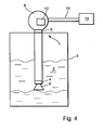
- Fig. 4 relates to an embodiment of the invention Device in which the control / evaluation unit 13 via a connection 10th from a housing 8, in which the detector unit 12 can be found, deposed is. Otherwise, the structure of this embodiment substantially corresponds the embodiment shown in Fig. 2.
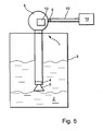
- the embodiment of the invention described in Fig. 5 Device differs from the embodiment shown in Fig. 4 only in that the second sealing stage 5 between the housing 8 with integrated detector unit 12 and the control / evaluation unit 13 is arranged is.
- the second sealing level 5 of the detector unit 12 is downstream. in the In contrast to this, in the embodiment shown in FIG. 4, the second one Preceding sealing level 5 of the detector unit 12.
- the field device 1 in Fig. 6 it is a vibration detector.
- the sensor 6 and the control / evaluation unit 13 are through the connecting pipe 9, in which the Detector unit 12 is connected to each other.
- the connecting pipe 9 is made by utilizing the bore 16 e.g. put under pressure, preferably with a protective gas such as argon. This hole will then closed by a screw plug, in addition can be welded.
- the overpressure is then passed through the Detector unit 12 - e.g. a pressure switch - monitored. Results at the first sealing step 4 a leak, the pressure drops.
- the Detection unit also consist of a mechanical switch, the no further supply lines needed. Then you can with this Switch the sensor supply lines interrupted or be shorted. Both cases are clear error conditions evaluable.
- the advantage of this solution is the simple and cheap design. But it can also separate lines for feeding the detector unit be used. This way even sophisticated solutions can be realized.
- the first sealing stage 4, the second sealing stage 5, the detector unit 12 and the Connecting pipe 9 form here the modular unit 17.
- An alternative Design is that two additional seals only part of the Connecting tube 9, in which the detector unit 12 is located, seal and that then only put this smaller modular unit 17 under pressure becomes. This will e.g. the electronics in the rule / evaluation unit 13 is not exposed to the pressure.
- a general alternative is that not one Overpressure, but a negative pressure is generated. In the case of a vacuum then it is at the detector unit 12 also to a Vacuum switch.
- Fig. 7 shows a tuning fork as a sensor 6, which via a connecting pipe 9 is connected to the transmitter 7.
- the transition of the sensor 6 to Connecting pipe 9 is over the first 4 and the transition of the Connecting pipe 9 to the transmitter 7 is via the second sealing stage. 5 locked.
- the connecting tube 9 is connected to an intermediate medium 18th filled, which is supposed to be a gas here. This goes hand in hand with that the first 4 and the second sealing stage 5 are made gas-tight.
- the second sealing step 5 be a known glass feedthrough.
- the Intermediate medium 18 is monitored by the detection unit 12. there For example, it is an optical MEMS gas sensor.
- One Such a sensor takes advantage of the fact that most gases have a specific Have absorption line for infrared light.
- the sensor 12 measures the transmission of light through the gas.
- the wavelength of the absorbed light gives Information about the gas and the intensity of the absorbed light allows the determination of the amount of gas.
Landscapes
- Physics & Mathematics (AREA)
- Electromagnetism (AREA)
- Thermal Sciences (AREA)
- Fluid Mechanics (AREA)
- General Physics & Mathematics (AREA)
- Examining Or Testing Airtightness (AREA)
- Testing Or Calibration Of Command Recording Devices (AREA)
Abstract
Description
Bei einer konventionellen Verdrahtung mit Leitungen kommt bevorzugt, da sehr kostengünstig, eine Kabelverschraubung als zweite Dichtstufe zum Einsatz. Die Anforderungen an die zweite Dichtstufe sind dann nicht besonders groß, wenn das Gehäuse wie üblich über ein semipermeables Filter (z.B. Gore Tex) belüftet wird. Dann muß die zweite Dichtstufe, sprich die Kabelverschraubung, entsprechend den derzeitig gültigen Normen lediglich für ca. eine Minute 150 % des maximalen Drucks im Gehäuse ohne sichtbare Leckage aushalten.
Insbesondere handelt es sich bei dem Gehäuse um den Transmitter, in dem die zumindest eine elektrische und/oder die elektronische Komponente des Feldgeräts angeordnet ist. Darüber hinaus wird vorgeschlagen, daß die zweite Dichtstufe zwischen dem Transmitter und einer entfernten Kontrollstelle angeordnet ist. Als besonders günstig wird es im Zusammenhang mit der erfindungsgemäßen Vorrichtung angesehen, wenn die erste Dichtstufe und/oder die zweite Dichtstufe gasdicht ausgestaltet sind/ist.
- Fig. 1:
- eine schematische Darstellung einer ersten Ausführungsform der erfindungsgemäßen Vorrichtung;
- Fig. 2:
- eine schematische Darstellung einer zweiten Ausführungsform der erfindungsgemäßen Vorrichtung;
- Fig. 3:
- eine schematische Darstellung einer dritten Ausführungsform der erfindungsgemäßen Vorrichtung;
- Fig. 4:
- eine schematische Darstellung einer vierten Ausführungsform der erfindungsgemäßen Vorrichtung;
- Fig. 5:
- eine schematische Darstellung einer fünften Ausführungsform der erfindungsgemäßen Vorrichtung;
- Fig. 6:
- eine schematische Darstellung einer sechsten Ausführungsform der erfindungsgemäßen Vorrichtung; und
- Fig. 7:
- eine schematische Darstellung einer siebten Ausführungsform der erfindungsgemäßen Vorrichtung.
- 1
- Feldgerät
- 2
- Prozeßmedium
- 3
- Behälter
- 4
- Erste Dichtstufe
- 5
- Zweite Dichtstufe
- 6
- Sensor
- 7
- Transmitter
- 8
- Gehäuse
- 9
- Verbindungsrohr
- 10
- Verbindungsleitung
- 11
- Entfernte Kontrollstelle
- 12
- Detektoreinheit
- 13
- Regel-/Auswerteeinheit
- 14
- Oberfläche des Prozeßmediums
- 15
- Zusatzmodul
- 16
- Bohrung
- 17
- Modulare Einheit
- 18
- Zwischenmedium
Claims (16)
- Vorrichtung zur Überwachung eines Feldgeräts (1) zur Bestimmung und/oder Überwachung einer physikalischen und/oder chemischen Prozeßgröße eines Prozeßmediums (2) mit einer ersten dem Prozeß zugewandten Dichtstufe (4) und zumindest einem Gehäuse (7; 8; 9) mit einem vorgegebenen Innenvolumen, das auf der vom Prozeß abgewandten Seite der ersten Dichtstufe (4) vorgesehen ist, wobei Energie über die erste Dichtstufe (4) in Richtung des Prozeßmediums (2) übertragbar ist, wobei diese Energie mit dem Prozeßmedium (2) in Wechselwirkung tritt, wobei in dem Gehäuse (7; 8; 9) zumindest eine Detektoreinheit (12) vorgesehen ist, die zumindest eine Zustandsgröße des Innenvolumens des Gehäuses (7; 8; 9) überwacht, wobei eine Regel- /Auswerteeinheit (13) anhand der mit dem Prozeßmedium (2) wechselwirkenden Energie die physikalische und/oder chemische Prozeßgröße bestimmt, und wobei die Regel-/Auswerteeinheit (13) und/oder eine anderweitige Überwachungseinheit anhand der überwachten Zustandsgröße in dem Innenvolumen des Gehäuses (7; 8; 9) erkennt und/oder anzeigt, ob die Dichtstufe (4) das Gehäuse (7; 8; 9) gegen den Prozeß hin abdichtet und/oder einen Alarm ausgibt, sobald die überwachte Zustandsgröße in dem Innenvolumen des Gehäuses (7; 8; 9) einen vorgegebenen Grenzwert erreicht.
- Vorrichtung nach Anspruch 1,
wobei das Gehäuse (8; 9) zwischen der ersten Dichtstufe (4) und einem Transmitter (7) vorgesehen ist, in dem zumindest eine elektrische und/oder elektronische Komponente des Feldgeräts (1) angeordnet ist. - Vorrichtung nach Anspruch 1,
wobei das Gehäuse (8) und der Transmitter (7) zur Aufnahme der zumindest einen elektrischen und/oder elektronischen Komponente des Feldgeräts (1) über eine Verbindungsleitung (10) miteinander verbunden sind. - Vorrichtung nach Anspruch 1,
wobei das Gehäuse (8) den Transmitter (7) von dem Sensor (6) zur Erfassung der physikalischen und/oder chemischen Prozeßgröße bzw. vom Prozeß trennt bzw. absetzt. - Vorrichtung nach Anspruch 4,
wobei die erste Dichtstufe (4) in dem Endbereich des Gehäuses (9) angeordnet ist, der dem Prozeß zugewandt ist, und wobei eine zweite Dichtstufe (5) in dem Endbereich des Gehäuses (9) vorgesehen ist, der vom Prozeß abgewandt ist. - Vorrichtung nach Anspruch 1,
wobei es sich bei dem Gehäuse (8) um den Transmitter (7) handelt, in dem die zumindest eine elektrische und/oder die elektronische Komponente des Feldgeräts (1) angeordnet ist. - Vorrichtung nach Anspruch 1 oder 6,
wobei die zweite Dichtstufe (5) zwischen dem Transmitter (7) und einer entfernten Kontrollstelle (11) angeordnet ist. - Vorrichtung nach Anspruch 1, 4 und 5,
wobei die erste Dichtstufe (4) und/oder die zweite Dichtstufe (5) gasdicht ausgestaltet sind/ist. - Vorrichtung nach Anspruch 1,
wobei die Detektoreinheit (12) in das Gehäuse (8), in den Transmitter (8) oder in das Verbindungsrohr (9) integriert ist - Vorrichtung nach Anspruch 1,
wobei die Detektoreinheit (12) als Zusatzmodul (15) ausgebildet ist, das an das Gehäuse (8), an den Transmitter (7) oder an das Verbindungsrohr (9) adaptierbar ist. - Vorrichtung nach einem oder mehreren der Ansprüche 1, 9 oder 10,
wobei mindestens ein Teil des Transmitters (7), des Gehäuses (8) oder des Verbindungsrohrs (9) unter Unterdruck steht, und wobei die Detektoreinheit (12) ein Druckmeßgerät, ein Vakuumschalter und/oder ein Druckschalter ist. - Vorrichtung nach einem oder mehreren der Ansprüche 1, 9 oder 10,
wobei mindestens ein Teil des Transmitters (7), des Gehäuses (8) oder des Verbindungsrohrs (9) unter Überdruck steht, und wobei die Detektoreinheit (12) ein Druckmeßgerät und/oder ein Druckschalter ist. - Vorrichtung nach einem oder mehreren der Ansprüche 1, 9 oder 10,
wobei in der Detektoreinheit (12) eine bewegliche Einheit vorgesehen ist, die sich aus einer Ruhelage herausbewegt, sobald die überwachte Zustandsgröße in dem Innenvolumen des Transmitters (7), des Gehäuses (8) oder des Verbindungsrohrs (9) einen vorgegebenen Grenzwert erreicht. - Vorrichtung nach Anspruch 11, 12 oder 13,
wobei ein Teil des Transmitters (7), des Gehäuses (8) oder des Verbindungsrohrs (9) und die Detektoreinheit (12) eine modulare Einheit (17) bilden. - Vorrichtung nach mindestens einem der vorhergehenden Ansprüche,
wobei mindestens in einem Teil des Transmitters (7), des Gehäuses (8) und/oder des Verbindungsrohrs (9) ein Zwischenmedium (18) befindlich ist, welches sich von innerhalb des Behälters (3) befindlichen Medien, insbesondere dem Prozessmedium (2) unterscheidet, und wobei die Detektoreinheit (12) derartig ausgestaltet ist, dass sie das Zwischenmedium (18) überwacht. - Vorrichtung nach Anspruch 15,
wobei es sich bei dem Zwischenmedium (18) um ein Gas handelt, und wobei es sich bei der Detektoreinheit (12) um einen entsprechenden Gassensor handelt.
Applications Claiming Priority (4)
| Application Number | Priority Date | Filing Date | Title |
|---|---|---|---|
| DE10327499 | 2003-06-17 | ||
| DE10327499 | 2003-06-17 | ||
| DE10355784A DE10355784A1 (de) | 2003-06-17 | 2003-11-26 | Vorrichtung zur Überwachung eines Feldgeräts |
| DE10355784 | 2003-11-26 |
Publications (3)
| Publication Number | Publication Date |
|---|---|
| EP1507133A2 true EP1507133A2 (de) | 2005-02-16 |
| EP1507133A3 EP1507133A3 (de) | 2007-02-14 |
| EP1507133B1 EP1507133B1 (de) | 2016-06-29 |
Family
ID=33566005
Family Applications (1)
| Application Number | Title | Priority Date | Filing Date |
|---|---|---|---|
| EP04012545.2A Expired - Lifetime EP1507133B1 (de) | 2003-06-17 | 2004-05-27 | Vorrichtung zur Überwachung eines Feldgeräts |
Country Status (2)
| Country | Link |
|---|---|
| US (1) | US7095365B2 (de) |
| EP (1) | EP1507133B1 (de) |
Cited By (5)
| Publication number | Priority date | Publication date | Assignee | Title |
|---|---|---|---|---|
| WO2005093375A3 (de) * | 2004-03-23 | 2005-11-10 | Endress & Hauser Gmbh & Co Kg | Sicherheitsmodul und messanordnung mit sicherheitsmodul |
| US7251985B2 (en) | 2004-03-23 | 2007-08-07 | Endress + Hauser Flowtec Ag | Safety module and measuring arrangement with safety module |
| DE102007049525A1 (de) | 2007-10-15 | 2009-04-16 | Endress + Hauser Wetzer Gmbh + Co. Kg | Feldgerät der Prozessautomatisierung |
| EP2067008A1 (de) * | 2006-09-29 | 2009-06-10 | Vega Grieshaber KG | Silo-inhaltsmessungssystem |
| DE102021134449A1 (de) | 2021-12-23 | 2023-06-29 | Endress+Hauser SE+Co. KG | Montageanordnung mit einem vibronischen Sensor |
Families Citing this family (28)
| Publication number | Priority date | Publication date | Assignee | Title |
|---|---|---|---|---|
| US7319401B2 (en) * | 2004-08-27 | 2008-01-15 | Rosemount Tank Radar Ab | Radar level gauge system with variable alarm limits |
| US7259712B1 (en) * | 2004-09-30 | 2007-08-21 | Siemens Milltronics Process Instruments Inc. | Antenna with integral sealing member for a radar-based level measurement system |
| US7453393B2 (en) * | 2005-01-18 | 2008-11-18 | Siemens Milltronics Process Instruments Inc. | Coupler with waveguide transition for an antenna in a radar-based level measurement system |
| US7363811B2 (en) * | 2005-04-07 | 2008-04-29 | Endress + Hauser Flowtec Ag | Measurement pickup |
| EP1710545A1 (de) * | 2005-04-07 | 2006-10-11 | Endress + Hauser Flowtec AG | Messaufnehmer mit Überdruckschutzvorrichtung |
| DE602005020434D1 (de) * | 2005-06-13 | 2010-05-20 | Siemens Milltronics Proc Instr | Hornantenne mit Verbundwerkstoffstrahler |
| US7467548B2 (en) * | 2005-10-14 | 2008-12-23 | Rosemount Tank Radar Ab | Radar level gauge system and coupling |
| US20070090992A1 (en) * | 2005-10-21 | 2007-04-26 | Olov Edvardsson | Radar level gauge system and transmission line probe for use in such a system |
| US7994796B2 (en) * | 2006-03-01 | 2011-08-09 | Vega Grieshaber Kg | Circuit arrangement and method for monitoring the function of a vibration level switch and/or a fill level measuring apparautus |
| US20100007444A1 (en) * | 2006-04-20 | 2010-01-14 | Anis Nurashikin Nordin | GHz Surface Acoustic Resonators in RF-CMOS |
| US8143681B2 (en) * | 2006-04-20 | 2012-03-27 | The George Washington University | Saw devices, processes for making them, and methods of use |
| DE102006032250B4 (de) * | 2006-07-12 | 2008-08-14 | Vega Grieshaber Kg | Sensoren mit integrierter Solarenergieerzeugung |
| US20090124513A1 (en) * | 2007-04-20 | 2009-05-14 | Patricia Berg | Multiplex Biosensor |
| US7855676B2 (en) * | 2009-03-10 | 2010-12-21 | Rosemount Tank Radar Ab | Radar level gauge system with leakage detection |
| DE102010040866A1 (de) * | 2010-09-16 | 2012-03-22 | Endress + Hauser Gmbh + Co. Kg | Feldgerät zur Bestimmung und/oder Überwachung einer chemischen oder physikalischen Prozessgröße in der Automatisierungstechnik |
| US8960004B2 (en) | 2010-09-29 | 2015-02-24 | The George Washington University | Synchronous one-pole surface acoustic wave resonator |
| DE102011078060A1 (de) * | 2011-06-24 | 2012-12-27 | Endress + Hauser Gmbh + Co. Kg | Vorrichtung zur Bestimmung oder Überwachung des Füllstandes eines Füllguts in einem Behälter |
| DE102012014267B4 (de) | 2012-07-19 | 2020-12-24 | Krohne S.A. | Nach dem Radar-Prinzip arbeitendes Füllstandmessgerät |
| DE102013112025A1 (de) * | 2013-10-31 | 2015-04-30 | Endress + Hauser Gmbh + Co. Kg | Vorrichtung zur Bestimmung oder Überwachung des Füllstands eines Mediums in einem Behälter |
| DE102013113766A1 (de) * | 2013-12-10 | 2015-06-11 | Endress + Hauser Gmbh + Co. Kg | Vorrichtung zur Messung des Füllstands eines Füllguts in einem Behälter |
| US9488511B2 (en) * | 2014-09-30 | 2016-11-08 | Rosemount Inc. | Magnetic flowmeter with vapor permeation sensor |
| EP3029433A1 (de) * | 2014-12-01 | 2016-06-08 | Honeywell International Inc. | Diagnosesignal zur Ankündigung des Versagens der primären Dichtung in einem Füllstandmesser |
| DE102015100415A1 (de) * | 2015-01-13 | 2016-07-14 | Krohne Messtechnik Gmbh | Vorrichtung zur Bestimmung des Füllstands eines Mediums |
| EP3067711B1 (de) | 2015-03-13 | 2019-12-18 | Honeywell International Inc. | Vorrichtung und Verfahren zur Einstellung geführter Wellenradarimpulsbreite zur Optimierung von Messungen |
| JP6384382B2 (ja) * | 2015-03-30 | 2018-09-05 | 日本精機株式会社 | 液面位置検出装置 |
| US10634542B2 (en) | 2016-06-22 | 2020-04-28 | Honeywell International Inc. | Adaptive sync control in radar level sensors |
| DE102019112933A1 (de) | 2019-05-16 | 2020-11-19 | Endress+Hauser SE+Co. KG | Feldgerät der Automatisierungstechnik für einen Einsatz in explosionsgefährdeten Bereichen, Verfahren zur Überwachung der Gasdichtheit in einem Feldgerät und Verfahren zur Herstellung eines ebensolchen Feldgeräts |
| LU102493B1 (de) * | 2021-01-18 | 2022-07-18 | Mecorad Gmbh | Messvorrichtung und Verfahren zur Messung elektromagnetischer Wellen |
Family Cites Families (17)
| Publication number | Priority date | Publication date | Assignee | Title |
|---|---|---|---|---|
| US4670754A (en) * | 1985-12-30 | 1987-06-02 | Transamerica Delaval, Inc. | Microwave tank-contents level measuring assembly with a phase controlled lens |
| DE9005509U1 (de) | 1990-05-15 | 1990-07-19 | ELB-Füllstandsgeräte Bundschuh GmbH + Co, 6140 Bensheim | Leckagesonde für Flüssigkeiten |
| DE4042235A1 (de) * | 1990-06-28 | 1992-01-02 | Urich Manfred | Fuellstandsmessvorrichtung |
| US5351036A (en) * | 1991-12-10 | 1994-09-27 | Clark-Reliance Corporation | Microwave-based point liquid level monitoring system |
| DE9219100U1 (de) * | 1992-04-14 | 1997-11-27 | Kistner, Rolf, 83607 Holzkirchen | Vorrichtung zur Überprüfung der Dichtigkeit |
| US5406842A (en) * | 1993-10-07 | 1995-04-18 | Motorola, Inc. | Method and apparatus for material level measurement using stepped frequency microwave signals |
| DE4336494C2 (de) * | 1993-10-26 | 1995-11-02 | Endress Hauser Gmbh Co | Vorrichtung zur Füllstandsmessung in Behältern |
| US5588461A (en) * | 1994-04-08 | 1996-12-31 | Philipp Brothers Chemicals, Inc. | Hazardous material containment system |
| US5872494A (en) * | 1997-06-27 | 1999-02-16 | Rosemount Inc. | Level gage waveguide process seal having wavelength-based dimensions |
| EP0887658B1 (de) * | 1997-06-27 | 2004-08-25 | EADS Deutschland GmbH | Füllstandmessradargerät |
| DE19916953A1 (de) | 1999-04-15 | 2000-11-02 | Fluidtech Gmbh | Vorrichtung zum Anzeigen und/oder Kontrollieren von Fluiden |
| DE19925185C2 (de) | 1999-05-26 | 2002-11-28 | Fafnir Gmbh | Füllstand-Meßvorrichtung |
| US6310574B1 (en) * | 1999-08-05 | 2001-10-30 | Vega Grieshaber Kg | Level transmitter |
| US6337655B1 (en) * | 2000-01-26 | 2002-01-08 | Ohmart Vega Corporation | Apparatus and method for liquid level measurement in a sounding tube |
| EP1217352A1 (de) * | 2000-12-20 | 2002-06-26 | ABBPATENT GmbH | Verfahren und Einrichtung zur Ermittlung von Leckagen an der Dichtung eines Ventils |
| AT5410U1 (de) | 2001-04-27 | 2002-06-25 | Steyr Powertrain Ag & Co Kg | Verfahren und vorrichtung zur ermittlung des füllzustandes einer einheit |
| US6935173B2 (en) * | 2002-06-25 | 2005-08-30 | Maxima Technologies & Systems, Inc. | Liquid level sensing device |
-
2004
- 2004-05-27 EP EP04012545.2A patent/EP1507133B1/de not_active Expired - Lifetime
- 2004-06-17 US US10/868,950 patent/US7095365B2/en not_active Expired - Lifetime
Cited By (6)
| Publication number | Priority date | Publication date | Assignee | Title |
|---|---|---|---|---|
| WO2005093375A3 (de) * | 2004-03-23 | 2005-11-10 | Endress & Hauser Gmbh & Co Kg | Sicherheitsmodul und messanordnung mit sicherheitsmodul |
| US7251985B2 (en) | 2004-03-23 | 2007-08-07 | Endress + Hauser Flowtec Ag | Safety module and measuring arrangement with safety module |
| EP2067008A1 (de) * | 2006-09-29 | 2009-06-10 | Vega Grieshaber KG | Silo-inhaltsmessungssystem |
| DE102007049525A1 (de) | 2007-10-15 | 2009-04-16 | Endress + Hauser Wetzer Gmbh + Co. Kg | Feldgerät der Prozessautomatisierung |
| DE102021134449A1 (de) | 2021-12-23 | 2023-06-29 | Endress+Hauser SE+Co. KG | Montageanordnung mit einem vibronischen Sensor |
| US12326420B2 (en) | 2021-12-23 | 2025-06-10 | Endress+Hauser SE+Co. KG | Mounting arrangement with a vibronic sensor |
Also Published As
| Publication number | Publication date |
|---|---|
| US7095365B2 (en) | 2006-08-22 |
| US20050017896A1 (en) | 2005-01-27 |
| EP1507133B1 (de) | 2016-06-29 |
| EP1507133A3 (de) | 2007-02-14 |
Similar Documents
| Publication | Publication Date | Title |
|---|---|---|
| EP1507133B1 (de) | Vorrichtung zur Überwachung eines Feldgeräts | |
| DE10355784A1 (de) | Vorrichtung zur Überwachung eines Feldgeräts | |
| EP1891343B1 (de) | Kugelgelenk mit sensoreinrichtung und verfahren zur dichtigkeitserkennung | |
| CN107810388B (zh) | 具有故障检测单元的模块化密封设备 | |
| EP0637713A1 (de) | Diagnose-System für Regel- und Absperrventile | |
| EP3198251B1 (de) | Vorrichtung und verfahren zum kalibrieren einer folienkammer zur leckdetektion | |
| WO2014195076A2 (de) | Messgerät | |
| EP1065488B1 (de) | Relativdrucksensor | |
| WO2014170332A2 (de) | Explosionsgeschütze gehäuse und verfahren zur überwachung einer ausreichenden dichtigkeit des explosionsgeschützten gehäuses | |
| DE102008014801A1 (de) | Leckageüberwachung bei zylindrischen Anordnungen | |
| EP1953517B1 (de) | Anordnung zur Überwachung der Dichtigkeit eines evakuierten Raums | |
| DE102012104412A1 (de) | Wechselarmatur | |
| EP1621863A2 (de) | Vorrichtung zur Erfassung einer Leckage | |
| WO2004048915A1 (de) | Messumformer mit lecküberwachung | |
| DE102013020896B4 (de) | Vorrichtung und Verfahren zur Überwachung eines Objektes in einem explosionsgeschützten Bereich mittels Ultraschall | |
| EP1728049B1 (de) | Sicherheitsmodul und messanordnung mit sicherheitsmodul | |
| DE102011084906A1 (de) | Verfahren zur Überwachung einer Pumpe für Flüssigkeiten und Pumpe | |
| EP4040064A1 (de) | Verfahren und anordnung zur feststellung von kältemittelleckagen in einem kältekreislauf, der in einem geschlossenen gehäuse angeordnet ist | |
| US7143636B2 (en) | Field device for determining and/or monitoring a process variable | |
| DE102021119081A1 (de) | Druckmittler mit Überwachungsfunktion | |
| DE4028883A1 (de) | Verfahren und einrichtung zur anzeige eines ungewoehnlichen betriebszustandes einer maschine oder betriebseinrichtung, insbesondere leckanzeige bzw. leckmelder | |
| WO2009050160A2 (de) | Feldgerät der prozessautomatisierung | |
| CN208240177U (zh) | 一种高精度的可燃气体报警仪 | |
| CN107560806A (zh) | 一种屏蔽泵流体泄漏的检测系统和方法 | |
| DE10325799B3 (de) | Verfahren zur Überprüfung der Vakuumfestigkeit einer Druckübertragungsflüssigkeit in einem Druckmessumformer sowie Einrichtung zur Durchführung des Verfahrens |
Legal Events
| Date | Code | Title | Description |
|---|---|---|---|
| PUAI | Public reference made under article 153(3) epc to a published international application that has entered the european phase |
Free format text: ORIGINAL CODE: 0009012 |
|
| AK | Designated contracting states |
Kind code of ref document: A2 Designated state(s): AT BE BG CH CY CZ DE DK EE ES FI FR GB GR HU IE IT LI LU MC NL PL PT RO SE SI SK TR |
|
| AX | Request for extension of the european patent |
Extension state: AL HR LT LV MK |
|
| PUAL | Search report despatched |
Free format text: ORIGINAL CODE: 0009013 |
|
| AK | Designated contracting states |
Kind code of ref document: A3 Designated state(s): AT BE BG CH CY CZ DE DK EE ES FI FR GB GR HU IE IT LI LU MC NL PL PT RO SE SI SK TR |
|
| AX | Request for extension of the european patent |
Extension state: AL HR LT LV MK |
|
| 17P | Request for examination filed |
Effective date: 20070303 |
|
| 17Q | First examination report despatched |
Effective date: 20070801 |
|
| AKX | Designation fees paid |
Designated state(s): AT BE BG CH CY CZ DE DK EE ES FI FR GB GR HU IE IT LI LU MC NL PL PT RO SE SI SK TR |
|
| REG | Reference to a national code |
Ref country code: DE Ref legal event code: R079 Ref document number: 502004015236 Country of ref document: DE Free format text: PREVIOUS MAIN CLASS: G01F0023000000 Ipc: G01F0023284000 |
|
| GRAP | Despatch of communication of intention to grant a patent |
Free format text: ORIGINAL CODE: EPIDOSNIGR1 |
|
| RIC1 | Information provided on ipc code assigned before grant |
Ipc: G01F 23/284 20060101AFI20160111BHEP |
|
| INTG | Intention to grant announced |
Effective date: 20160126 |
|
| GRAS | Grant fee paid |
Free format text: ORIGINAL CODE: EPIDOSNIGR3 |
|
| GRAA | (expected) grant |
Free format text: ORIGINAL CODE: 0009210 |
|
| AK | Designated contracting states |
Kind code of ref document: B1 Designated state(s): AT BE BG CH CY CZ DE DK EE ES FI FR GB GR HU IE IT LI LU MC NL PL PT RO SE SI SK TR |
|
| REG | Reference to a national code |
Ref country code: GB Ref legal event code: FG4D Free format text: NOT ENGLISH |
|
| REG | Reference to a national code |
Ref country code: CH Ref legal event code: EP |
|
| REG | Reference to a national code |
Ref country code: DE Ref legal event code: R081 Ref document number: 502004015236 Country of ref document: DE Owner name: ENDRESS+HAUSER SE+CO. KG, DE Free format text: FORMER OWNER: ENDRESS + HAUSER GMBH + CO. KG, 79689 MAULBURG, DE |
|
| REG | Reference to a national code |
Ref country code: AT Ref legal event code: REF Ref document number: 809476 Country of ref document: AT Kind code of ref document: T Effective date: 20160715 |
|
| REG | Reference to a national code |
Ref country code: IE Ref legal event code: FG4D Free format text: LANGUAGE OF EP DOCUMENT: GERMAN |
|
| REG | Reference to a national code |
Ref country code: DE Ref legal event code: R096 Ref document number: 502004015236 Country of ref document: DE |
|
| PG25 | Lapsed in a contracting state [announced via postgrant information from national office to epo] |
Ref country code: FI Free format text: LAPSE BECAUSE OF FAILURE TO SUBMIT A TRANSLATION OF THE DESCRIPTION OR TO PAY THE FEE WITHIN THE PRESCRIBED TIME-LIMIT Effective date: 20160629 |
|
| REG | Reference to a national code |
Ref country code: NL Ref legal event code: MP Effective date: 20160629 |
|
| PG25 | Lapsed in a contracting state [announced via postgrant information from national office to epo] |
Ref country code: GR Free format text: LAPSE BECAUSE OF FAILURE TO SUBMIT A TRANSLATION OF THE DESCRIPTION OR TO PAY THE FEE WITHIN THE PRESCRIBED TIME-LIMIT Effective date: 20160930 Ref country code: NL Free format text: LAPSE BECAUSE OF FAILURE TO SUBMIT A TRANSLATION OF THE DESCRIPTION OR TO PAY THE FEE WITHIN THE PRESCRIBED TIME-LIMIT Effective date: 20160629 Ref country code: SE Free format text: LAPSE BECAUSE OF FAILURE TO SUBMIT A TRANSLATION OF THE DESCRIPTION OR TO PAY THE FEE WITHIN THE PRESCRIBED TIME-LIMIT Effective date: 20160629 |
|
| PG25 | Lapsed in a contracting state [announced via postgrant information from national office to epo] |
Ref country code: SK Free format text: LAPSE BECAUSE OF FAILURE TO SUBMIT A TRANSLATION OF THE DESCRIPTION OR TO PAY THE FEE WITHIN THE PRESCRIBED TIME-LIMIT Effective date: 20160629 Ref country code: RO Free format text: LAPSE BECAUSE OF FAILURE TO SUBMIT A TRANSLATION OF THE DESCRIPTION OR TO PAY THE FEE WITHIN THE PRESCRIBED TIME-LIMIT Effective date: 20160629 Ref country code: EE Free format text: LAPSE BECAUSE OF FAILURE TO SUBMIT A TRANSLATION OF THE DESCRIPTION OR TO PAY THE FEE WITHIN THE PRESCRIBED TIME-LIMIT Effective date: 20160629 Ref country code: CZ Free format text: LAPSE BECAUSE OF FAILURE TO SUBMIT A TRANSLATION OF THE DESCRIPTION OR TO PAY THE FEE WITHIN THE PRESCRIBED TIME-LIMIT Effective date: 20160629 |
|
| PG25 | Lapsed in a contracting state [announced via postgrant information from national office to epo] |
Ref country code: ES Free format text: LAPSE BECAUSE OF FAILURE TO SUBMIT A TRANSLATION OF THE DESCRIPTION OR TO PAY THE FEE WITHIN THE PRESCRIBED TIME-LIMIT Effective date: 20160629 Ref country code: PL Free format text: LAPSE BECAUSE OF FAILURE TO SUBMIT A TRANSLATION OF THE DESCRIPTION OR TO PAY THE FEE WITHIN THE PRESCRIBED TIME-LIMIT Effective date: 20160629 Ref country code: PT Free format text: LAPSE BECAUSE OF FAILURE TO SUBMIT A TRANSLATION OF THE DESCRIPTION OR TO PAY THE FEE WITHIN THE PRESCRIBED TIME-LIMIT Effective date: 20161031 |
|
| REG | Reference to a national code |
Ref country code: DE Ref legal event code: R097 Ref document number: 502004015236 Country of ref document: DE |
|
| PLBE | No opposition filed within time limit |
Free format text: ORIGINAL CODE: 0009261 |
|
| STAA | Information on the status of an ep patent application or granted ep patent |
Free format text: STATUS: NO OPPOSITION FILED WITHIN TIME LIMIT |
|
| REG | Reference to a national code |
Ref country code: FR Ref legal event code: PLFP Year of fee payment: 14 |
|
| PG25 | Lapsed in a contracting state [announced via postgrant information from national office to epo] |
Ref country code: DK Free format text: LAPSE BECAUSE OF FAILURE TO SUBMIT A TRANSLATION OF THE DESCRIPTION OR TO PAY THE FEE WITHIN THE PRESCRIBED TIME-LIMIT Effective date: 20160629 |
|
| 26N | No opposition filed |
Effective date: 20170330 |
|
| PG25 | Lapsed in a contracting state [announced via postgrant information from national office to epo] |
Ref country code: BG Free format text: LAPSE BECAUSE OF FAILURE TO SUBMIT A TRANSLATION OF THE DESCRIPTION OR TO PAY THE FEE WITHIN THE PRESCRIBED TIME-LIMIT Effective date: 20160929 Ref country code: SI Free format text: LAPSE BECAUSE OF FAILURE TO SUBMIT A TRANSLATION OF THE DESCRIPTION OR TO PAY THE FEE WITHIN THE PRESCRIBED TIME-LIMIT Effective date: 20160629 Ref country code: LU Free format text: LAPSE BECAUSE OF NON-PAYMENT OF DUE FEES Effective date: 20170531 |
|
| REG | Reference to a national code |
Ref country code: CH Ref legal event code: PL |
|
| PG25 | Lapsed in a contracting state [announced via postgrant information from national office to epo] |
Ref country code: MC Free format text: LAPSE BECAUSE OF FAILURE TO SUBMIT A TRANSLATION OF THE DESCRIPTION OR TO PAY THE FEE WITHIN THE PRESCRIBED TIME-LIMIT Effective date: 20160629 |
|
| REG | Reference to a national code |
Ref country code: IE Ref legal event code: MM4A |
|
| PG25 | Lapsed in a contracting state [announced via postgrant information from national office to epo] |
Ref country code: CH Free format text: LAPSE BECAUSE OF NON-PAYMENT OF DUE FEES Effective date: 20170531 Ref country code: LI Free format text: LAPSE BECAUSE OF NON-PAYMENT OF DUE FEES Effective date: 20170531 |
|
| REG | Reference to a national code |
Ref country code: DE Ref legal event code: R081 Ref document number: 502004015236 Country of ref document: DE Owner name: ENDRESS+HAUSER SE+CO. KG, DE Free format text: FORMER OWNER: ENDRESS + HAUSER GMBH + CO. KG, 79689 MAULBURG, DE |
|
| PG25 | Lapsed in a contracting state [announced via postgrant information from national office to epo] |
Ref country code: LU Free format text: LAPSE BECAUSE OF NON-PAYMENT OF DUE FEES Effective date: 20170527 |
|
| REG | Reference to a national code |
Ref country code: BE Ref legal event code: MM Effective date: 20170531 |
|
| PG25 | Lapsed in a contracting state [announced via postgrant information from national office to epo] |
Ref country code: IE Free format text: LAPSE BECAUSE OF NON-PAYMENT OF DUE FEES Effective date: 20170527 |
|
| REG | Reference to a national code |
Ref country code: FR Ref legal event code: PLFP Year of fee payment: 15 |
|
| REG | Reference to a national code |
Ref country code: AT Ref legal event code: MM01 Ref document number: 809476 Country of ref document: AT Kind code of ref document: T Effective date: 20170527 |
|
| PG25 | Lapsed in a contracting state [announced via postgrant information from national office to epo] |
Ref country code: BE Free format text: LAPSE BECAUSE OF NON-PAYMENT OF DUE FEES Effective date: 20170531 Ref country code: AT Free format text: LAPSE BECAUSE OF NON-PAYMENT OF DUE FEES Effective date: 20170527 |
|
| PG25 | Lapsed in a contracting state [announced via postgrant information from national office to epo] |
Ref country code: HU Free format text: LAPSE BECAUSE OF FAILURE TO SUBMIT A TRANSLATION OF THE DESCRIPTION OR TO PAY THE FEE WITHIN THE PRESCRIBED TIME-LIMIT; INVALID AB INITIO Effective date: 20040527 |
|
| PG25 | Lapsed in a contracting state [announced via postgrant information from national office to epo] |
Ref country code: CY Free format text: LAPSE BECAUSE OF NON-PAYMENT OF DUE FEES Effective date: 20160629 |
|
| PG25 | Lapsed in a contracting state [announced via postgrant information from national office to epo] |
Ref country code: TR Free format text: LAPSE BECAUSE OF FAILURE TO SUBMIT A TRANSLATION OF THE DESCRIPTION OR TO PAY THE FEE WITHIN THE PRESCRIBED TIME-LIMIT Effective date: 20160629 |
|
| P01 | Opt-out of the competence of the unified patent court (upc) registered |
Effective date: 20230601 |
|
| PGFP | Annual fee paid to national office [announced via postgrant information from national office to epo] |
Ref country code: IT Payment date: 20230526 Year of fee payment: 20 Ref country code: FR Payment date: 20230525 Year of fee payment: 20 Ref country code: DE Payment date: 20230519 Year of fee payment: 20 |
|
| PGFP | Annual fee paid to national office [announced via postgrant information from national office to epo] |
Ref country code: GB Payment date: 20230522 Year of fee payment: 20 |
|
| REG | Reference to a national code |
Ref country code: DE Ref legal event code: R071 Ref document number: 502004015236 Country of ref document: DE |
|
| REG | Reference to a national code |
Ref country code: GB Ref legal event code: PE20 Expiry date: 20240526 |
|
| PG25 | Lapsed in a contracting state [announced via postgrant information from national office to epo] |
Ref country code: GB Free format text: LAPSE BECAUSE OF EXPIRATION OF PROTECTION Effective date: 20240526 |
|
| PG25 | Lapsed in a contracting state [announced via postgrant information from national office to epo] |
Ref country code: GB Free format text: LAPSE BECAUSE OF EXPIRATION OF PROTECTION Effective date: 20240526 |