EP1506825A1 - Device and method for the continous casting of a bimetallic strip through a twin roll casting machine - Google Patents
Device and method for the continous casting of a bimetallic strip through a twin roll casting machine Download PDFInfo
- Publication number
- EP1506825A1 EP1506825A1 EP03017502A EP03017502A EP1506825A1 EP 1506825 A1 EP1506825 A1 EP 1506825A1 EP 03017502 A EP03017502 A EP 03017502A EP 03017502 A EP03017502 A EP 03017502A EP 1506825 A1 EP1506825 A1 EP 1506825A1
- Authority
- EP
- European Patent Office
- Prior art keywords
- wall
- meniscus
- chamber
- lateral
- molten metal
- Prior art date
- Legal status (The legal status is an assumption and is not a legal conclusion. Google has not performed a legal analysis and makes no representation as to the accuracy of the status listed.)
- Granted
Links
Images


Classifications
-
- B—PERFORMING OPERATIONS; TRANSPORTING
- B22—CASTING; POWDER METALLURGY
- B22D—CASTING OF METALS; CASTING OF OTHER SUBSTANCES BY THE SAME PROCESSES OR DEVICES
- B22D11/00—Continuous casting of metals, i.e. casting in indefinite lengths
- B22D11/06—Continuous casting of metals, i.e. casting in indefinite lengths into moulds with travelling walls, e.g. with rolls, plates, belts, caterpillars
- B22D11/0622—Continuous casting of metals, i.e. casting in indefinite lengths into moulds with travelling walls, e.g. with rolls, plates, belts, caterpillars formed by two casting wheels
-
- B—PERFORMING OPERATIONS; TRANSPORTING
- B22—CASTING; POWDER METALLURGY
- B22D—CASTING OF METALS; CASTING OF OTHER SUBSTANCES BY THE SAME PROCESSES OR DEVICES
- B22D11/00—Continuous casting of metals, i.e. casting in indefinite lengths
- B22D11/007—Continuous casting of metals, i.e. casting in indefinite lengths of composite ingots, i.e. two or more molten metals of different compositions being used to integrally cast the ingots
Definitions
- the invention refers to continuous casting of a bimetallic strip through a twin roll casting machine.
- the invention deals with a distributor device of the molten metal components on the crystallizing rolls and the corresponding utilization method, in order to prevent the mixing of the above mentioned metals, to keep separated and distinguished their respective meniscuses and thus to ensure a clear separation at the metals interface in the cast product.
- Patent JP 5277661 is an attempt at solving these inconveniences. It considers a separation wall to keep the two molten metals separated. This solution, however, has big limitations as well: as a matter of fact, there is nothing to prevent the liquid under the wall from flowing through the gaps between the same wall and the rolls into the bath above and vice versa. There are therefore the same inconveniences as with JP '659.
- Patent JP 4009251 on the contrary, describes a device to plate the strip on one side only and considers two nozzles of the same length which discharge their respective molten metals at a higher level than the roll's profile. Moreover, a vertical separation wall, placed on the centre line of the two rolls, should ensure the separation between the two liquid baths. Not even this patent, however, can give any guarantee to prevent the liquids from getting mixed. It furthermore does not allow to plate both sides of the strip. To avoid these inconveniences, the Applicant has studied, designed and constructed the device as described hereinafter.
- the main object is to construct a distributor device for the molten metals in association with a method of utilization which can guarantee a clear separation interface between the inner and the outer layers, as well as the absence of any defects in the cast strip.
- Another object of the present invention is to cast a strip plated on one side only or on both sides.
- a device for continuous casting a metallic strip through a twin roll casting machine said metallic strip having a metallic coating on at least one side thereof, according to the characterising features of claim 1. Further advantageous embodiments are subject matter of dependent claims. Further, the invention provides a method of continuous casting a metal strip through a twin roll casting machine, said metallic strip having a metallic coating on at least one side thereof by using a distributor device, according to claim 9.
- the production of a strip having a low carbon core coated on both sides with stainless steel has remarkable advantages mainly for the automotive and the electrical appliances industry.
- the galvanizing process of the steel sheet is indeed no longer necessary, and this facilitates above all the pressing of the steel sheet itself.
- a thinner layer of protective paint is required with a resulting reduction in costs and in terms of environmental impact of the galvanizing and painting process.
- the device and method according to the present invention allows to cast a bi-metallic strip with a total thickness in the of 1-5 mm range through a twin roll continuous casting machine, whose width can range from 500 - 1500 mm starting from the molten component metals as e.g. carbon steel and stainless steel.
- the stainless steel coating in the cast strip can vary from 5 % to 25 % of the total strip thickness.
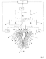
- Fig. 1 shows partly and schematically crystallizing rolls 1 a and 1 b of a twin roll casting machine for continuous casting a metallic strip. Arrows D and E indicate their turning directions, respectively.
- a distributor means 5 which distributes molten metals A through a nozzle or pipe 6 from a central under-tundish 3 and molten metals B and C through a nozzle or pipe 4a, 4b from under-tundishes 2a or 2b, respectively, on the crystallizing rolls 1 a, 1 b to provide a metallic strip 18 made of three metals A, B and C.
- the crystallizing rolls 1 a, 1 b are arranged parallel to each other at a given distance d which substantially defines the starting thickness of the cast product or strip.
- the rolls 1 a and 1 b define a substantially V-shaped top space, and the distributor device 5 is placed in this substantially V-shaped top space and mounted between a non-shown front wall and the rear wall 40 perpendicular to the axis of the crystallizing rolls 1 a, 1 b.
- the strip 18 is coated on both sides.
- the strip core contains metal A, e.g. low carbon steel, while the two lateral sides contain metals B and C which may be e.g. stainless steel to form the strip coatings on both sides.
- the distributor device 5 is made up of two spaced vertical walls 7a, 7b, which define a centre chamber 30 for the molten metal A, intermediate walls 8a, 8b, which define with the two spaced vertical walls 7a, 7b, two lateral chambers 31 for the molten metal B and C, respectively, and side walls 9a, 9b, which define with said intermediate walls 8a, 8b, two small spaces 33, respectively, which communicate with said lateral chambers 31 through openings 10a, 10b, respectively, provided close to a bottom portion 35.
- the side walls 9a, 9b are shorter than the intermediate walls 8a, 8b and define a passage for liquid metal B or C, discharged into the lateral chambers 31.
- the liquid metal B and C forms a meniscus 21a, 21b, respectively, in the substantially V-shaped top space.
- the intermediate walls 8a, 8b with bottom openings 10a, 10b and the side walls 9a, 9b are suitable to reduce the kinetic energy of the molten metal B, C coming from the under-tundishes 2a, 2b, respectively, thus ensuring a substantially flat and turbulence-free "lateral" meniscus 21a, 21b.
- a meniscus 20 is formed in the centre chamber 30, containing the molten metal A.
- the level of the meniscus 20 of the centre chamber 30 is monitored by a sensor means 38. Further, there are sensor means 38a for the meniscus 21a and 38b for the meniscus 21b.
- the sensor means 38, 38a and 38b are connected to a control unit 39 for individually feeding molten metals A, Band C to the centre chamber 30 and the lateral chambers 31 in response to signals of said sensor means 38, 38a, 38b to maintain the meniscus 30 and 21a, 21b on a predetermined level.
- ⁇ h there is a level difference ⁇ h between the said meniscus 20 of the centre chamber 30 and the meniscus 21a of the lateral chamber 31, which is kept constant through the sensor means 38 and the control unit 39 as described above.
- the difference ⁇ h depends on casting parameters, e.
- the levels of the three meniscus 20, 21a, 21b are individually controllable through the above mentioned sensor means 38, 38a, 38b and the control unit.
- FIG 2 shows only half of the device 5 and casting machine of figure 1, i. e. the right portion.
- molten metal B which is confined between the vertical wall 7a and its respective crystallizing roll 1a, comes into contact with a cool surface of the roll 1a itself and starts to solidify forming a semi-skin S 1a .
- the semi-skin S 1a formation takes place in the circumference arc, which extends from a contact point P 1 of the lateral meniscus 21a with said roll 1a up to the point P 2 which corresponds to the vertical downward extension of the vertical wall 7a.
- the point P 2 is called “double point", and above the double point P 2 only the formation of the semi-skin S 1a takes place until reaching its maximum thickness at P 2 .
- the solidification of molten metal A, contained in the centre chamber 30 starts, and semi-skin S 2a begins to form over the semi-skin S 1a .
- a point of minimum distance between the rolls 1a, 1b is called the "kissing point”.
- the semi-skins S 2a , S 2b which have been previously formed on the two rotating crystallizing rolls 1a, 1b, combine to form the desired plated strip 18, which is made of the metal A in its core or centre part and, in figure 2, of metal B on its right surface.
- the width of the centre chamber 30 determines the position of the double point P 2 , and the position of the double point P 2 defines the final thickness of the semi-skin S 1a and therefore the thickness of the strip coating.
- a gap 19 is formed between the vertical wall 7a and the casting roll 1a.
- the rotation of said roll 1a causes the dragging of the molten metal B contained in the side space 37 below the bottom portion 35. This creates a dynamic pressure on said metal B in said passage gap 19. Owing to this additional pressure, a none desired passage of molten metal B from said lateral space 37 into the centre chamber 30 might take place through said gap 19 resulting into a mixing with the molten metal A.
- the level of the centre meniscus 20 is kept higher than the side meniscus 21a by the amount ⁇ h, as mentioned above.
- a hat of metal A which determines a ferrostatic pressure on the gap 19, which is sufficient to compensate the total pressure determined by the molten metal B in the same zone. Therefore, the passage of metal B through the gap 19 is prevented, and the semi-skin S 2a , which is formed below the point P 2 , does not contain any unwanted traces of the other metal.
- Figure 3 corresponds essentially to figure 2.
- the distributor device 5 is modified to have no side wall 9a.
- Figure 4 is similar to figure 3, however with a further modified distributor means 5, wherein the side wall 9a and a part of the bottom portion 35 outside the lateral chamber 31 are omitted.
- the distributor device as shown in figure 2, 3 and 4 can be used only for a half for strip coating on one side only.
- the upstream feeding system includes only two under-tundishes 2a or 2b, 3 with their respective nozzles 4a or 4b, 6.
Landscapes
- Engineering & Computer Science (AREA)
- Mechanical Engineering (AREA)
- Continuous Casting (AREA)
Abstract
Description
- The invention refers to continuous casting of a bimetallic strip through a twin roll casting machine.
In particular the invention deals with a distributor device of the molten metal components on the crystallizing rolls and the corresponding utilization method, in order to prevent the mixing of the above mentioned metals, to keep separated and distinguished their respective meniscuses and thus to ensure a clear separation at the metals interface in the cast product. - The methods used for the continuous casting of bimetallic strip through a twin roll casting machine, starting from different molten metals, are known from the technique.
The solutions in which two pouring nozzles, one for each type of metal, are used to obtain a strip plated either on both sides or on one side only, are particularly well known.
More precisely, patent JP 5277659 describes a method to plate the strip on both sides and considers two pouring nozzles of different lengths which discharge the molten metals at different levels into their respective baths between crystallizing rolls and the containment side plates. An evident disadvantage of this solution is the unavoidable mixing of the two liquids and therefore the fact that it is not possible to have a distinct start of solidification for each molten metal, or a semi-skin for each metal, and thus to obtain a clear separation interface between the two metals in the cast product.
Patent JP 5277661 is an attempt at solving these inconveniences. It considers a separation wall to keep the two molten metals separated. This solution, however, has big limitations as well: as a matter of fact, there is nothing to prevent the liquid under the wall from flowing through the gaps between the same wall and the rolls into the bath above and vice versa. There are therefore the same inconveniences as with JP '659.
Patent JP 4009251, on the contrary, describes a device to plate the strip on one side only and considers two nozzles of the same length which discharge their respective molten metals at a higher level than the roll's profile. Moreover, a vertical separation wall, placed on the centre line of the two rolls, should ensure the separation between the two liquid baths. Not even this patent, however, can give any guarantee to prevent the liquids from getting mixed. It furthermore does not allow to plate both sides of the strip.
To avoid these inconveniences, the Applicant has studied, designed and constructed the device as described hereinafter. - The main object is to construct a distributor device for the molten metals in association with a method of utilization which can guarantee a clear separation interface between the inner and the outer layers, as well as the absence of any defects in the cast strip.
- Another object of the present invention is to cast a strip plated on one side only or on both sides.
- According to the invention there is provided a device for continuous casting a metallic strip through a twin roll casting machine, said metallic strip having a metallic coating on at least one side thereof, according to the characterising features of claim 1. Further advantageous embodiments are subject matter of dependent claims. Further, the invention provides a method of continuous casting a metal strip through a twin roll casting machine, said metallic strip having a metallic coating on at least one side thereof by using a distributor device, according to claim 9.
- With the device and the method according to the invention the production of a strip having a low carbon core coated on both sides with stainless steel has remarkable advantages mainly for the automotive and the electrical appliances industry. For this type of steel strip the galvanizing process of the steel sheet is indeed no longer necessary, and this facilitates above all the pressing of the steel sheet itself. Also, a thinner layer of protective paint is required with a resulting reduction in costs and in terms of environmental impact of the galvanizing and painting process.
- The device and method according to the present invention allows to cast a bi-metallic strip with a total thickness in the of 1-5 mm range through a twin roll continuous casting machine, whose width can range from 500 - 1500 mm starting from the molten component metals as e.g. carbon steel and stainless steel. The stainless steel coating in the cast strip can vary from 5 % to 25 % of the total strip thickness.
-
- Fig. 1:
- shows schematically a vertical section through the crystallizing rolls and the distributor means and features of the cast control;
- Fig. 2:
- shows an enlarged vertical section through one crystallizing roll and the associated half distributor means;
- Fig. 3:
- shows a section similar to Fig. 1, however with a modified distributor means without a side-wall; and
- Fig. 4:
- shows a view similar to Fig. 3 with a further embodiment of distributor means.
- Fig. 1 shows partly and schematically crystallizing
rolls 1 a and 1 b of a twin roll casting machine for continuous casting a metallic strip. Arrows D and E indicate their turning directions, respectively. Above the crystallizing orcasting rolls 1 a, 1 b there is provided a distributor means 5, which distributes molten metals A through a nozzle orpipe 6 from a central under-tundish 3 and molten metals B and C through a nozzle orpipe tundishes rolls 1 a, 1 b to provide ametallic strip 18 made of three metals A, B and C. - The crystallizing
rolls 1 a, 1 b are arranged parallel to each other at a given distance d which substantially defines the starting thickness of the cast product or strip. Therolls 1 a and 1 b define a substantially V-shaped top space, and the distributor device 5 is placed in this substantially V-shaped top space and mounted between a non-shown front wall and therear wall 40 perpendicular to the axis of the crystallizingrolls 1 a, 1 b. - With the arrangement of fig. 1 the
strip 18 is coated on both sides. The strip core contains metal A, e.g. low carbon steel, while the two lateral sides contain metals B and C which may be e.g. stainless steel to form the strip coatings on both sides. - In the first embodiment shown in figure 1, the distributor device 5 is made up of two spaced
vertical walls 7a, 7b, which define acentre chamber 30 for the molten metal A,intermediate walls 8a, 8b, which define with the two spacedvertical walls 7a, 7b, twolateral chambers 31 for the molten metal B and C, respectively, andside walls intermediate walls 8a, 8b, twosmall spaces 33, respectively, which communicate with saidlateral chambers 31 throughopenings 10a, 10b, respectively, provided close to abottom portion 35. Theside walls intermediate walls 8a, 8b and define a passage for liquid metal B or C, discharged into thelateral chambers 31. - The liquid metal B and C forms a
meniscus 21a, 21b, respectively, in the substantially V-shaped top space. Theintermediate walls 8a, 8b withbottom openings 10a, 10b and theside walls tundishes meniscus 21a, 21b. Ameniscus 20 is formed in thecentre chamber 30, containing the molten metal A. - The level of the
meniscus 20 of thecentre chamber 30 is monitored by a sensor means 38. Further, there are sensor means 38a for themeniscus 21a and 38b for the meniscus 21b. The sensor means 38, 38a and 38b are connected to acontrol unit 39 for individually feeding molten metals A, Band C to thecentre chamber 30 and thelateral chambers 31 in response to signals of said sensor means 38, 38a, 38b to maintain themeniscus meniscus 20 of thecentre chamber 30 and themeniscus 21a of thelateral chamber 31, which is kept constant through the sensor means 38 and thecontrol unit 39 as described above. The difference Δh depends on casting parameters, e. g. speed, etc., and on the properties of the metals to be matched, e. g. density, viscosity, etc. The levels of the threemeniscus - The casting of the
metallic strip 18 by using the distributor means 5 for different molten metals is now described with reference to figure 2, which shows only half of the device 5 and casting machine of figure 1, i. e. the right portion. According to figure 2, molten metal B which is confined between thevertical wall 7a and its respective crystallizingroll 1a, comes into contact with a cool surface of theroll 1a itself and starts to solidify forming a semi-skin S1a. The semi-skin S1a formation takes place in the circumference arc, which extends from a contact point P1 of thelateral meniscus 21a with saidroll 1a up to the point P2 which corresponds to the vertical downward extension of thevertical wall 7a. - The point P2 is called "double point", and above the double point P2 only the formation of the semi-skin S1a takes place until reaching its maximum thickness at P2. Below the point P2 the solidification of molten metal A, contained in the
centre chamber 30 starts, and semi-skin S2a begins to form over the semi-skin S1a. A point of minimum distance between therolls 1a, 1b is called the "kissing point". In correspondence with this point, the semi-skins S2a, S2b, which have been previously formed on the two rotating crystallizingrolls 1a, 1b, combine to form the desiredplated strip 18, which is made of the metal A in its core or centre part and, in figure 2, of metal B on its right surface. - The width of the
centre chamber 30 determines the position of the double point P2, and the position of the double point P2 defines the final thickness of the semi-skin S1a and therefore the thickness of the strip coating. In correspondence with the double point P2, agap 19 is formed between thevertical wall 7a and thecasting roll 1a. The rotation of saidroll 1a causes the dragging of the molten metal B contained in theside space 37 below thebottom portion 35. This creates a dynamic pressure on said metal B in saidpassage gap 19. Owing to this additional pressure, a none desired passage of molten metal B from saidlateral space 37 into thecentre chamber 30 might take place through saidgap 19 resulting into a mixing with the molten metal A. In order to avoid such drawback, the level of thecentre meniscus 20 is kept higher than theside meniscus 21a by the amount Δh, as mentioned above. In this way, there is provided a hat of metal A which determines a ferrostatic pressure on thegap 19, which is sufficient to compensate the total pressure determined by the molten metal B in the same zone. Therefore, the passage of metal B through thegap 19 is prevented, and the semi-skin S2a, which is formed below the point P2, does not contain any unwanted traces of the other metal. - Figure 3 corresponds essentially to figure 2. However, the distributor device 5 is modified to have no
side wall 9a. Figure 4 is similar to figure 3, however with a further modified distributor means 5, wherein theside wall 9a and a part of thebottom portion 35 outside thelateral chamber 31 are omitted. - The distributor device as shown in figure 2, 3 and 4 can be used only for a half for strip coating on one side only. In this case, the upstream feeding system includes only two under-
tundishes respective nozzles
Claims (10)
- A device for continuos casting a metallic strip through a twin roll casting machine, said metallic strip having a metallic coating on at least one side thereof, characterised by
a distributor means (5) for different molten metals (A, B, C), said distributor means (5) being provided between the crystallizing rolls (1a, 1b) above their kissing point, said distributor means (5) comprising:a front wall and a rear wall (40) perpendicular to the axis of the crystallizing rolls (1a, 1b);two spaced vertical walls (7a) defining together with the front and rear wall and the surfaces of said crystallizing rolls (1a, 1b) a centre chamber (30) for receiving a first molten metal (A); andat least one intermediate wall (8a) extending outside one of the vertical walls (7a) from a bottom portion (35) to define with the associated vertical wall (7a) a lateral chamber (31) for a second or a second and a third molten metal (B, C), respectively,each intermediate wall (8a) comprising at least one opening (10a). - The device according to claim 1, wherein each opening (10a) is provided close to the bottom portion (35).
- The device according to claim 1, wherein the front wall (40) and the rear wall (41) are side plates.
- The device according to a proceeding claim, comprising at least one side wall (9a) extending outside said at least one intermediate wall (8a) from said bottom portion (35) close to the casting rolls (1a, 1b) to form a small chamber (33), respectively.
- The device according to claim 4, wherein each side wall (9a) is shorter than each intermediate wall (8a) and defines a lateral passage for the second or third molten metal (B, C) contained in the lateral chamber (31) once the side wall (9a) has been passed.
- The device according to a proceeding claim, wherein a lower end of each vertical wall (7a) defines a gap (19) with respect to the crystallizing roll (1a), said gap (19) linking said centre chamber (30) with a lateral space (37) formed beneath the bottom portion (35) receiving molten metal having passed the side walls (9a).
- The device according to a proceeding claim, characterised by providing a meniscus (21a) formed in an even manner in the lateral space (33) between the outside of the crystallizing roll (1a) and the intermediate wall (8a) by the second or third molten metal (B, C), once a side wall (9a) has been passed.
- The device according to a proceeding claim, characterised by providing a level of the meniscus (21a, 21b), which is lower (Δh) than the level of a meniscus (20) of the centre chamber (30).
- The device according to a proceeding claim, characterised by sensor means (38) for the level of the meniscus (20) of the centre chamber (30) and sensor means (38a, 38b) for the level of a meniscus (21a) in at least one lateral space (33), and a control unit (39) for individually feeding molten metals to the centre chamber (30) and at least one lateral chamber (31) in response to signals of said sensor means (38, 38a, 38b).
- A method of continuos casting a metallic strip through a twin roll casting machine, said metal strip having a metallic coating on at least one side thereof by using a distributor device according to claim 1, comprising the following steps:feeding a first molten metal to the centre chamber to obtaining a central meniscus;feeding a second or a second and a third molten metal, respectively, to a lateral chamber, respectively, to obtain at least one lateral meniscus; andmaintaining the level of the central meniscus compared to the level of at least one lateral meniscus by an amount Δh higher, which is determined by casting parameters and properties of the metals to be matched.
Priority Applications (3)
| Application Number | Priority Date | Filing Date | Title |
|---|---|---|---|
| AT03017502T ATE318192T1 (en) | 2003-08-04 | 2003-08-04 | DEVICE AND METHOD FOR PRODUCING THIN BIMETAL STRIP USING A 2-ROLL CASTING DEVICE |
| DE60303630T DE60303630T2 (en) | 2003-08-04 | 2003-08-04 | Apparatus and method for producing thin bimetallic strip with a 2-roll casting apparatus |
| EP03017502A EP1506825B1 (en) | 2003-08-04 | 2003-08-04 | Device and method for the continous casting of a bimetallic strip through a twin roll casting machine |
Applications Claiming Priority (1)
| Application Number | Priority Date | Filing Date | Title |
|---|---|---|---|
| EP03017502A EP1506825B1 (en) | 2003-08-04 | 2003-08-04 | Device and method for the continous casting of a bimetallic strip through a twin roll casting machine |
Publications (2)
| Publication Number | Publication Date |
|---|---|
| EP1506825A1 true EP1506825A1 (en) | 2005-02-16 |
| EP1506825B1 EP1506825B1 (en) | 2006-02-22 |
Family
ID=33560763
Family Applications (1)
| Application Number | Title | Priority Date | Filing Date |
|---|---|---|---|
| EP03017502A Expired - Lifetime EP1506825B1 (en) | 2003-08-04 | 2003-08-04 | Device and method for the continous casting of a bimetallic strip through a twin roll casting machine |
Country Status (3)
| Country | Link |
|---|---|
| EP (1) | EP1506825B1 (en) |
| AT (1) | ATE318192T1 (en) |
| DE (1) | DE60303630T2 (en) |
Cited By (1)
| Publication number | Priority date | Publication date | Assignee | Title |
|---|---|---|---|---|
| CN102120255A (en) * | 2010-12-30 | 2011-07-13 | 中国第一重型机械股份公司 | Manufacturing equipment of laminated composite steel plate and working method thereof |
Citations (7)
| Publication number | Priority date | Publication date | Assignee | Title |
|---|---|---|---|---|
| JPS62259641A (en) * | 1986-05-02 | 1987-11-12 | Mitsubishi Heavy Ind Ltd | Production of clad steel plate |
| JPH038538A (en) * | 1989-06-06 | 1991-01-16 | Mitsubishi Electric Corp | Manufacture of clad material |
| JPH03297542A (en) * | 1990-04-18 | 1991-12-27 | Nisshin Steel Co Ltd | Twin roll type continuous casting method and intermediate vessel for pouring molten metal used for same |
| JPH049251A (en) * | 1990-04-26 | 1992-01-14 | Toshiba Corp | Apparatus for continuously casting cladded plate |
| JPH04138847A (en) * | 1990-09-28 | 1992-05-13 | Nippon Steel Corp | Quench solidified clad foil composed of metal and alloy and production thereof |
| JPH0768349A (en) * | 1993-09-01 | 1995-03-14 | Nippon Steel Corp | Method and apparatus for continuously casting clad thin cast sheet |
| DE19815010C1 (en) * | 1998-01-23 | 1999-05-06 | Schloemann Siemag Ag | Continuous casting of one- or two-side clad thin metal strip |
-
2003
- 2003-08-04 EP EP03017502A patent/EP1506825B1/en not_active Expired - Lifetime
- 2003-08-04 AT AT03017502T patent/ATE318192T1/en not_active IP Right Cessation
- 2003-08-04 DE DE60303630T patent/DE60303630T2/en not_active Expired - Fee Related
Patent Citations (7)
| Publication number | Priority date | Publication date | Assignee | Title |
|---|---|---|---|---|
| JPS62259641A (en) * | 1986-05-02 | 1987-11-12 | Mitsubishi Heavy Ind Ltd | Production of clad steel plate |
| JPH038538A (en) * | 1989-06-06 | 1991-01-16 | Mitsubishi Electric Corp | Manufacture of clad material |
| JPH03297542A (en) * | 1990-04-18 | 1991-12-27 | Nisshin Steel Co Ltd | Twin roll type continuous casting method and intermediate vessel for pouring molten metal used for same |
| JPH049251A (en) * | 1990-04-26 | 1992-01-14 | Toshiba Corp | Apparatus for continuously casting cladded plate |
| JPH04138847A (en) * | 1990-09-28 | 1992-05-13 | Nippon Steel Corp | Quench solidified clad foil composed of metal and alloy and production thereof |
| JPH0768349A (en) * | 1993-09-01 | 1995-03-14 | Nippon Steel Corp | Method and apparatus for continuously casting clad thin cast sheet |
| DE19815010C1 (en) * | 1998-01-23 | 1999-05-06 | Schloemann Siemag Ag | Continuous casting of one- or two-side clad thin metal strip |
Non-Patent Citations (6)
| Title |
|---|
| PATENT ABSTRACTS OF JAPAN vol. 012, no. 137 (M - 690) 26 April 1988 (1988-04-26) * |
| PATENT ABSTRACTS OF JAPAN vol. 015, no. 117 (M - 1095) 20 March 1991 (1991-03-20) * |
| PATENT ABSTRACTS OF JAPAN vol. 016, no. 137 (M - 1231) 7 April 1992 (1992-04-07) * |
| PATENT ABSTRACTS OF JAPAN vol. 016, no. 157 (M - 1236) 16 April 1992 (1992-04-16) * |
| PATENT ABSTRACTS OF JAPAN vol. 016, no. 414 (M - 1303) 2 September 1992 (1992-09-02) * |
| PATENT ABSTRACTS OF JAPAN vol. 1995, no. 06 31 July 1995 (1995-07-31) * |
Cited By (1)
| Publication number | Priority date | Publication date | Assignee | Title |
|---|---|---|---|---|
| CN102120255A (en) * | 2010-12-30 | 2011-07-13 | 中国第一重型机械股份公司 | Manufacturing equipment of laminated composite steel plate and working method thereof |
Also Published As
| Publication number | Publication date |
|---|---|
| DE60303630D1 (en) | 2006-04-27 |
| EP1506825B1 (en) | 2006-02-22 |
| DE60303630T2 (en) | 2006-09-21 |
| ATE318192T1 (en) | 2006-03-15 |
Similar Documents
| Publication | Publication Date | Title |
|---|---|---|
| US8646513B2 (en) | Casting delivery nozzle | |
| US5716538A (en) | Discharge nozzle for continuous casting | |
| US6557623B2 (en) | Production method for continuous casting cast billet | |
| EP2017365B1 (en) | Method for manufacturing molten-metal plated steel band | |
| EP1506825B1 (en) | Device and method for the continous casting of a bimetallic strip through a twin roll casting machine | |
| JP2002316245A (en) | Method and apparatus for continuously casting cast strip | |
| JP2790781B2 (en) | Injection nozzle for continuous casting of wide thin slab | |
| KR100960322B1 (en) | The entry nozzle for twill roll strip caster | |
| EP0387006A2 (en) | Dual plate strip caster | |
| JPH06198397A (en) | Method and device of continuous casting of thin thickness dual layer sheet | |
| JP2001347348A (en) | Immersion nozzle for continuous casting | |
| KR100617254B1 (en) | Entry nozzle for twin-roll strip caster | |
| JP4673719B2 (en) | Dipping nozzle for continuous casting and method for continuous casting of steel | |
| JP2005125337A (en) | Immersion nozzle for thin cast slab continuous casting equipment and casting method | |
| JP2983400B2 (en) | Casting nozzle for twin belt continuous casting machine | |
| JPH06304704A (en) | Method for continuously casting double layer cast billet | |
| JPH07115125B2 (en) | Continuous casting method for multi-layer slab | |
| WO1990014906A1 (en) | Side feed tundish apparatus for the alloying and rapid solidification of molten materials | |
| JP3263482B2 (en) | Submerged floater for strip material | |
| JPH05329591A (en) | Method for preventing drift of molten steel poured in continuous casting mold | |
| JP2856959B2 (en) | Continuous casting method of steel slab using traveling magnetic field and static magnetic field | |
| JPH1128553A (en) | Method for supplying molten metal into continuous casting | |
| JPH07100605A (en) | Method for preventing narrowing and clogging of tundish nozzle in continuous casting | |
| JP2002113560A (en) | Continuous casting method | |
| JPH09253807A (en) | Method for continuously casting aluminum killed steel cast billet having small cross section |
Legal Events
| Date | Code | Title | Description |
|---|---|---|---|
| PUAI | Public reference made under article 153(3) epc to a published international application that has entered the european phase |
Free format text: ORIGINAL CODE: 0009012 |
|
| AK | Designated contracting states |
Kind code of ref document: A1 Designated state(s): AT BE BG CH CY CZ DE DK EE ES FI FR GB GR HU IE IT LI LU MC NL PT RO SE SI SK TR |
|
| AX | Request for extension of the european patent |
Extension state: AL LT LV MK |
|
| 17P | Request for examination filed |
Effective date: 20050520 |
|
| GRAP | Despatch of communication of intention to grant a patent |
Free format text: ORIGINAL CODE: EPIDOSNIGR1 |
|
| AKX | Designation fees paid |
Designated state(s): AT BE BG CH CY CZ DE DK EE ES FI FR GB GR HU IE IT LI LU MC NL PT RO SE SI SK TR |
|
| GRAS | Grant fee paid |
Free format text: ORIGINAL CODE: EPIDOSNIGR3 |
|
| GRAA | (expected) grant |
Free format text: ORIGINAL CODE: 0009210 |
|
| AK | Designated contracting states |
Kind code of ref document: B1 Designated state(s): AT BE BG CH CY CZ DE DK EE ES FI FR GB GR HU IE IT LI LU MC NL PT RO SE SI SK TR |
|
| PG25 | Lapsed in a contracting state [announced via postgrant information from national office to epo] |
Ref country code: SI Free format text: LAPSE BECAUSE OF FAILURE TO SUBMIT A TRANSLATION OF THE DESCRIPTION OR TO PAY THE FEE WITHIN THE PRESCRIBED TIME-LIMIT Effective date: 20060222 Ref country code: LI Free format text: LAPSE BECAUSE OF FAILURE TO SUBMIT A TRANSLATION OF THE DESCRIPTION OR TO PAY THE FEE WITHIN THE PRESCRIBED TIME-LIMIT Effective date: 20060222 Ref country code: BE Free format text: LAPSE BECAUSE OF FAILURE TO SUBMIT A TRANSLATION OF THE DESCRIPTION OR TO PAY THE FEE WITHIN THE PRESCRIBED TIME-LIMIT Effective date: 20060222 Ref country code: SK Free format text: LAPSE BECAUSE OF FAILURE TO SUBMIT A TRANSLATION OF THE DESCRIPTION OR TO PAY THE FEE WITHIN THE PRESCRIBED TIME-LIMIT Effective date: 20060222 Ref country code: RO Free format text: LAPSE BECAUSE OF FAILURE TO SUBMIT A TRANSLATION OF THE DESCRIPTION OR TO PAY THE FEE WITHIN THE PRESCRIBED TIME-LIMIT Effective date: 20060222 Ref country code: NL Free format text: LAPSE BECAUSE OF FAILURE TO SUBMIT A TRANSLATION OF THE DESCRIPTION OR TO PAY THE FEE WITHIN THE PRESCRIBED TIME-LIMIT Effective date: 20060222 Ref country code: FI Free format text: LAPSE BECAUSE OF FAILURE TO SUBMIT A TRANSLATION OF THE DESCRIPTION OR TO PAY THE FEE WITHIN THE PRESCRIBED TIME-LIMIT Effective date: 20060222 Ref country code: CH Free format text: LAPSE BECAUSE OF FAILURE TO SUBMIT A TRANSLATION OF THE DESCRIPTION OR TO PAY THE FEE WITHIN THE PRESCRIBED TIME-LIMIT Effective date: 20060222 |
|
| REG | Reference to a national code |
Ref country code: GB Ref legal event code: FG4D |
|
| REG | Reference to a national code |
Ref country code: CH Ref legal event code: EP |
|
| REG | Reference to a national code |
Ref country code: IE Ref legal event code: FG4D |
|
| REF | Corresponds to: |
Ref document number: 60303630 Country of ref document: DE Date of ref document: 20060427 Kind code of ref document: P |
|
| PG25 | Lapsed in a contracting state [announced via postgrant information from national office to epo] |
Ref country code: SE Free format text: LAPSE BECAUSE OF FAILURE TO SUBMIT A TRANSLATION OF THE DESCRIPTION OR TO PAY THE FEE WITHIN THE PRESCRIBED TIME-LIMIT Effective date: 20060522 Ref country code: DK Free format text: LAPSE BECAUSE OF FAILURE TO SUBMIT A TRANSLATION OF THE DESCRIPTION OR TO PAY THE FEE WITHIN THE PRESCRIBED TIME-LIMIT Effective date: 20060522 Ref country code: BG Free format text: LAPSE BECAUSE OF FAILURE TO SUBMIT A TRANSLATION OF THE DESCRIPTION OR TO PAY THE FEE WITHIN THE PRESCRIBED TIME-LIMIT Effective date: 20060522 |
|
| PG25 | Lapsed in a contracting state [announced via postgrant information from national office to epo] |
Ref country code: ES Free format text: LAPSE BECAUSE OF FAILURE TO SUBMIT A TRANSLATION OF THE DESCRIPTION OR TO PAY THE FEE WITHIN THE PRESCRIBED TIME-LIMIT Effective date: 20060602 |
|
| PG25 | Lapsed in a contracting state [announced via postgrant information from national office to epo] |
Ref country code: PT Free format text: LAPSE BECAUSE OF FAILURE TO SUBMIT A TRANSLATION OF THE DESCRIPTION OR TO PAY THE FEE WITHIN THE PRESCRIBED TIME-LIMIT Effective date: 20060724 |
|
| NLV1 | Nl: lapsed or annulled due to failure to fulfill the requirements of art. 29p and 29m of the patents act | ||
| PG25 | Lapsed in a contracting state [announced via postgrant information from national office to epo] |
Ref country code: IE Free format text: LAPSE BECAUSE OF NON-PAYMENT OF DUE FEES Effective date: 20060804 |
|
| PG25 | Lapsed in a contracting state [announced via postgrant information from national office to epo] |
Ref country code: MC Free format text: LAPSE BECAUSE OF NON-PAYMENT OF DUE FEES Effective date: 20060831 |
|
| REG | Reference to a national code |
Ref country code: CH Ref legal event code: PL |
|
| ET | Fr: translation filed | ||
| PLBE | No opposition filed within time limit |
Free format text: ORIGINAL CODE: 0009261 |
|
| STAA | Information on the status of an ep patent application or granted ep patent |
Free format text: STATUS: NO OPPOSITION FILED WITHIN TIME LIMIT |
|
| 26N | No opposition filed |
Effective date: 20061123 |
|
| GBPC | Gb: european patent ceased through non-payment of renewal fee |
Effective date: 20070804 |
|
| PG25 | Lapsed in a contracting state [announced via postgrant information from national office to epo] |
Ref country code: GR Free format text: LAPSE BECAUSE OF FAILURE TO SUBMIT A TRANSLATION OF THE DESCRIPTION OR TO PAY THE FEE WITHIN THE PRESCRIBED TIME-LIMIT Effective date: 20060523 Ref country code: CZ Free format text: LAPSE BECAUSE OF FAILURE TO SUBMIT A TRANSLATION OF THE DESCRIPTION OR TO PAY THE FEE WITHIN THE PRESCRIBED TIME-LIMIT Effective date: 20060222 |
|
| PG25 | Lapsed in a contracting state [announced via postgrant information from national office to epo] |
Ref country code: EE Free format text: LAPSE BECAUSE OF FAILURE TO SUBMIT A TRANSLATION OF THE DESCRIPTION OR TO PAY THE FEE WITHIN THE PRESCRIBED TIME-LIMIT Effective date: 20060222 |
|
| PG25 | Lapsed in a contracting state [announced via postgrant information from national office to epo] |
Ref country code: HU Free format text: LAPSE BECAUSE OF FAILURE TO SUBMIT A TRANSLATION OF THE DESCRIPTION OR TO PAY THE FEE WITHIN THE PRESCRIBED TIME-LIMIT Effective date: 20060823 Ref country code: LU Free format text: LAPSE BECAUSE OF NON-PAYMENT OF DUE FEES Effective date: 20060804 Ref country code: TR Free format text: LAPSE BECAUSE OF FAILURE TO SUBMIT A TRANSLATION OF THE DESCRIPTION OR TO PAY THE FEE WITHIN THE PRESCRIBED TIME-LIMIT Effective date: 20060222 |
|
| PGFP | Annual fee paid to national office [announced via postgrant information from national office to epo] |
Ref country code: DE Payment date: 20080901 Year of fee payment: 6 |
|
| PG25 | Lapsed in a contracting state [announced via postgrant information from national office to epo] |
Ref country code: CY Free format text: LAPSE BECAUSE OF FAILURE TO SUBMIT A TRANSLATION OF THE DESCRIPTION OR TO PAY THE FEE WITHIN THE PRESCRIBED TIME-LIMIT Effective date: 20060222 Ref country code: GB Free format text: LAPSE BECAUSE OF NON-PAYMENT OF DUE FEES Effective date: 20070804 |
|
| PGFP | Annual fee paid to national office [announced via postgrant information from national office to epo] |
Ref country code: AT Payment date: 20080725 Year of fee payment: 6 Ref country code: FR Payment date: 20080828 Year of fee payment: 6 Ref country code: IT Payment date: 20080812 Year of fee payment: 6 |
|
| REG | Reference to a national code |
Ref country code: FR Ref legal event code: ST Effective date: 20100430 |
|
| PG25 | Lapsed in a contracting state [announced via postgrant information from national office to epo] |
Ref country code: AT Free format text: LAPSE BECAUSE OF NON-PAYMENT OF DUE FEES Effective date: 20090804 |
|
| PG25 | Lapsed in a contracting state [announced via postgrant information from national office to epo] |
Ref country code: FR Free format text: LAPSE BECAUSE OF NON-PAYMENT OF DUE FEES Effective date: 20090831 Ref country code: DE Free format text: LAPSE BECAUSE OF NON-PAYMENT OF DUE FEES Effective date: 20100302 |
|
| PG25 | Lapsed in a contracting state [announced via postgrant information from national office to epo] |
Ref country code: IT Free format text: LAPSE BECAUSE OF NON-PAYMENT OF DUE FEES Effective date: 20090804 |