EP1506798A2 - Übungsgerät - Google Patents
Übungsgerät Download PDFInfo
- Publication number
- EP1506798A2 EP1506798A2 EP04018345A EP04018345A EP1506798A2 EP 1506798 A2 EP1506798 A2 EP 1506798A2 EP 04018345 A EP04018345 A EP 04018345A EP 04018345 A EP04018345 A EP 04018345A EP 1506798 A2 EP1506798 A2 EP 1506798A2
- Authority
- EP
- European Patent Office
- Prior art keywords
- machine
- panel
- given
- training
- zone
- Prior art date
- Legal status (The legal status is an assumption and is not a legal conclusion. Google has not performed a legal analysis and makes no representation as to the accuracy of the status listed.)
- Withdrawn
Links
Images


Classifications
-
- A—HUMAN NECESSITIES
- A63—SPORTS; GAMES; AMUSEMENTS
- A63B—APPARATUS FOR PHYSICAL TRAINING, GYMNASTICS, SWIMMING, CLIMBING, OR FENCING; BALL GAMES; TRAINING EQUIPMENT
- A63B24/00—Electric or electronic controls for exercising apparatus of preceding groups; Controlling or monitoring of exercises, sportive games, training or athletic performances
- A63B24/0003—Analysing the course of a movement or motion sequences during an exercise or trainings sequence, e.g. swing for golf or tennis
-
- A—HUMAN NECESSITIES
- A63—SPORTS; GAMES; AMUSEMENTS
- A63B—APPARATUS FOR PHYSICAL TRAINING, GYMNASTICS, SWIMMING, CLIMBING, OR FENCING; BALL GAMES; TRAINING EQUIPMENT
- A63B21/00—Exercising apparatus for developing or strengthening the muscles or joints of the body by working against a counterforce, with or without measuring devices
-
- A—HUMAN NECESSITIES
- A63—SPORTS; GAMES; AMUSEMENTS
- A63B—APPARATUS FOR PHYSICAL TRAINING, GYMNASTICS, SWIMMING, CLIMBING, OR FENCING; BALL GAMES; TRAINING EQUIPMENT
- A63B21/00—Exercising apparatus for developing or strengthening the muscles or joints of the body by working against a counterforce, with or without measuring devices
- A63B21/06—User-manipulated weights
- A63B21/062—User-manipulated weights including guide for vertical or non-vertical weights or array of weights to move against gravity forces
- A63B21/0626—User-manipulated weights including guide for vertical or non-vertical weights or array of weights to move against gravity forces with substantially vertical guiding means
- A63B21/0628—User-manipulated weights including guide for vertical or non-vertical weights or array of weights to move against gravity forces with substantially vertical guiding means for vertical array of weights
-
- A—HUMAN NECESSITIES
- A63—SPORTS; GAMES; AMUSEMENTS
- A63B—APPARATUS FOR PHYSICAL TRAINING, GYMNASTICS, SWIMMING, CLIMBING, OR FENCING; BALL GAMES; TRAINING EQUIPMENT
- A63B71/00—Games or sports accessories not covered in groups A63B1/00 - A63B69/00
- A63B71/0054—Features for injury prevention on an apparatus, e.g. shock absorbers
- A63B2071/009—Protective housings covering the working parts of the apparatus
-
- A—HUMAN NECESSITIES
- A63—SPORTS; GAMES; AMUSEMENTS
- A63B—APPARATUS FOR PHYSICAL TRAINING, GYMNASTICS, SWIMMING, CLIMBING, OR FENCING; BALL GAMES; TRAINING EQUIPMENT
- A63B2225/00—Miscellaneous features of sport apparatus, devices or equipment
- A63B2225/10—Multi-station exercising machines
- A63B2225/105—Multi-station exercising machines each station having its own resisting device, e.g. for training multiple users simultaneously
-
- A—HUMAN NECESSITIES
- A63—SPORTS; GAMES; AMUSEMENTS
- A63B—APPARATUS FOR PHYSICAL TRAINING, GYMNASTICS, SWIMMING, CLIMBING, OR FENCING; BALL GAMES; TRAINING EQUIPMENT
- A63B2225/00—Miscellaneous features of sport apparatus, devices or equipment
- A63B2225/12—Miscellaneous features of sport apparatus, devices or equipment with mirrors
Definitions
- the present invention relates to an exercise machine for performing anaerobic or aerobic exercises, which is designed to be installed rapidly in such a way as to ensure a minimum amount of space completely available for performing a training session both in an environment equipped for sports training and in a home environment, even when the space available for the machine is limited.
- each of the machines in the three abovementioned product lines has, in addition to a considerable weight, also a respective work or training zone which is contained inside an ideal volume which has a given form and is able to assume varying proportions depending on the physical attributes of the exercising user.
- This ideal volume has a form and extension which can be easily calculated on the basis of the type of movement which the user must perform in order to carry out the exercises.
- this volume comprises the minimum working volume within which the user is able to access the machine freely and exercise performing given movements, such that he/she is able to experience the exercising activity in a positive manner in that it is reasonably devoid of constraints. Therefore, in the case where two machines - which may also be identical - must be arranged alongside each other, the minimum training volumes of the two machines must be kept suitably separate from each other in order to avoid interference.
- the object of the present invention is to provide an exercise machine which is devoid of the abovementioned drawbacks and which comprises a work zone or work volume of given dimensions so as to ensure a minimum space completely available for performing a training session in accordance with the medical/sports program in question.
- a further object of the present invention is that the said equipment should be low-cost and allow installation of the machine rapidly by a person with little or no experience in installing gym equipment, also without the need for measuring instruments.
- a further object of the present invention is to provide a machine in which the abovementioned equipment should be able to separate the said work zone from a service zone comprising a load unit, so as to prevent unintentional interference with the latter in a simple and inexpensive manner.
- the said equipment is able to allow association of electrical equipment of varying nature with the said machine.
- an exercise machine is provided, the characteristic features of said machine being described in Claim 1.
- the present invention also relates to a multi-station exercise machine, comprising a plurality of training modules, each of which can be arranged with respect to the other modules depending on the requirements for management of the space within the environment in which the machine is installed.
- An object of the present invention is to provide a multi-station exercise machine, equipped with a plurality of exercise machines, each of which is devoid of the abovementioned drawbacks and which for this purpose is equipped with low-cost equipment able to ensure that the machine in question can be easily installed in keeping with the respective work zone/volume, so that the latter, within each station of the multi-station machine, can be freely accessed and used by a user during training and both before and after training.
- a further object of the present invention is that the said equipment should be such that the machine can be easily incorporated in the corresponding multi-station machine, that the multi-station machine may be regarded as a set of minimum training modules which can be combined in a modular manner, that it is low-cost and that the machine itself can be easily and rapidly installed in such a manner as to ensure that the spaces occupied by the machine are sufficient for performing training sessions correctly in accordance with the medical/sports program in question.
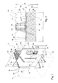
- FIG 1 denotes in its entirety, an exercise machine which comprises a frame 10, a work station or zone 20 designed to be used by a user for performing at least one exercising activity of a given type, and a service station or zone 30 situated adjacent to the work station 20 and provided with a load group 31.
- This load group 31 which can be seen partially in Figure 1 and in plan view in Figure 2, is able to exchange exercising power with the user by means of at least one interface 32, or operating device, connected to the load group 31 in a given manner so as to allow an exercise to be performed.
- the machine 1 may be equally well of the type comprising counterweights or of any other type for aerobic exercise suitable for exercising the cardiovascular system.
- the load group 31 comprises at least two load units 33 and 34 which are arranged alongside and separate from each other so that they may be operated separately by means of the interface 32 which in the case in question is a handle, which will be indicated using the same reference number.
- the handle 32 is associated with a cable 35 arranged between the two load units 33 and 34, to which it is connected by means of respective end portions which are arranged opposite to each other and act on opposite sides of the handle 32.
- the machine 1 also comprises a plurality of transmission devices which are in the form of drive pulleys 36 shown in Figure 1, each of the pulleys 36 being supported by the frame 10 between the two load units 33 and 34 along a path P, already described in Application No.
- the path P winds between the pulleys 36 and starts and terminates respectively at the load units 33 and 34.
- the two units 33 and 34 are both of the gravitational type and each of these comprises a plurality of blocks/counterweights 38 arranged on top of each other and supported by the frame 10 slidably along a vertical guide 39 for rectilinear movement.
- the operating device 32 may be equally well a handle or also a belt for clasping a heel or any other constructional form of an interface which can be operated by a user.
- the machine 1 is formed so that it is contained inside a prismatic volume V which in Figure 1 has been shown, for the sake of convenience, with a parallelepiped form and has maximum overall dimensions which depend on the type of machine 1, on the dimensions of the front section of the frame 10, on the form and arrangement of the path P, on whether the machine is a single-purpose or multifunctional machine, and therefore on the type of exercise which the user is able to perform freely on the machine 1, as well as on the build and physical attributes of the user.
- the volume V may be divided into at least two parts and in particular a work volume V L , which is arranged at the front and encloses the station 20, and a service volume V S , which is arranged at the rear and encloses the service station 30.
- the volume V L has a depth W L , which is calculated perpendicularly with respect to the direction 2
- the volume V S has a depth W S , which is also calculated perpendicularly with respect to the direction 2.
- the maximum cross-section of the volume V is inscribable inside a polygonal perimeter with a height H and width L which can be easily determined.
- the machine 1 also comprises a panel 40 supported transversely by the frame 10 in order to isolate the station 30 from the station 20.
- the panel 40 also has dimensions which are approximately equivalent to the height H and the width L of the polygonal perimeter so as to prevent a user engaged in training from voluntarily or involuntarily interacting with the service station 30 and so as to allow definition of the volume V L of the machine 1 as a minimum training module M which can be freely used during training.
- the work volume V L can be easily identified by means of direct measurement of the height H and width L of the panel 40 and the depth W, equal to W L +W S , which are indicated in Figure 2.
- the presence of the panel 40 facilitates installation of the machine in any environment since the panel 40 acts as a guide for arranging the machine 1 alongside walls or other apparatus or, even better, allows the composition of a plurality of modules M alongside each other, each of which can be freely used for training.
- This panel 40 may be formed by means of a single board 41 constructed by means of rolling or extrusion of metallic or plastic material of the opaque, transparent or translucent type so that it may be permeated by any shade of light, such that the panel 40 is more homogeneous with the environment in which the machine 1 must be installed, or so as to allow the passage of light produced by light sources of any colour, if necessary supported by the panel 40 as in the case of the apparatus which will be described more fully below.
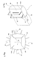
- the board 4 may be curved as in Figure 3d or also flat as in Figure 3b; moreover, the board 41 may be modular, thus obtained by means of combining transversely a plurality of elongated sheets 42, each of which may have more or less a homogeneous width 1 and extends preferably, but not exclusively, in the vertical direction in Figure 3a with a height H equal to that of the panel 40.
- the sheets 42 are joined together in pairs by means of at least one interlocking or hinged connection 43 so as to define, in the first case, a surface with a precise flat or discontinuous form and, in the second case, a discontinuous surface, the sheets 42 of which may be oriented as required with respect to each other, so as to make the panel 40 easily adaptable to the machine 1 and to the environment in which the machine 1 must be installed.
- the sheets 42 of the panel 40 may be rotated with respect to each other so as to allow a degree of personalization of the shape of the panel 40.
- At least one of the sheets 42 has a straight or curved form in plan view and sheets 42 with a straight and/or curved form in plan view may be combined together so as to obtain surface effects which may be modified if necessary over time by means of variation of the orientation, replacement in the event of damage or the like, or the addition of sheets 42 with a different profile for various reasons.
- the solution of constructing the panel 40 by means of the composition of longitudinal elements which are joined together by mean of connecting members 43 in order to form an interlocking or a hinged system is particularly interesting since it allows the formation of the panel 40 by combining sheets of limited width and with a longitudinal extension which may be defined as required.
- the sheets 42 may also be constructed by means of rolling or extrusion of metallic or plastic material of the opaque, transparent or translucent type for the reasons described above with reference to the board 41 so that the panel 40 is permeable to light, but could also be constructed of other material, for example wood.
- the possibility of producing panels 40 by means of the assembly of sheets 42 allows the formation of panels with any longitudinal extension, minimization of the end product stocks and an increase in the flexibility of production, favouring the optimized management of the warehouse stocks with positive effects on the financial management of the production activity.
- the connecting members 43 may also be installed laterally so as to allow joining with panels 40 of other machines 1.
- the machine 1 also comprises a horizontal element 48 which is visible in the sole Figure 2 where it is shown solely in plan view.
- the element 48 which can be installed on the floor, can be realized in the form of a footplate 48 which defines the work volume V L at the bottom or also more simply a mat having dimensions which indicate the depth of the station 20 and which therefore correspond approximately to a rectangle with sides W L and L able to provide visual information as to the plan-view extension and contours of the respective minimum training module M which can be freely used.
- the machine 1 comprises a unit 40' which is visible solely in Figure 2 for the sake of convenience of illustration and which comprises the panel 40 and the footplate 48 and provides an indication as to the overall dimensions of the minimum training volume M of the machine 1.
- the horizontal element 48 could perform the respective function of an element indicating the volume also if it were mounted on the frame 10 in a position above the station 20 or the station 30, if necessary supported by an upper edge of the respective panel 40.
- the element 48 could perform, in addition to the function of facilitating the operations of installing machines 1 alongside each other in close contact and protecting the module M, a covering function as well.
- the element 48 could be used to protect the machine 1 from atmospheric agents in external installations, but also prevent the deposition of dust on the operating device 32 and/or on everything which is contained within the service zone 30. Still with the same aim, the element 48 could be validly formed with an extension such as to cover the work zone 20 and/or the service zone 30.
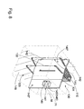
- this figure shows a non-limiting embodiment of a covering 48' which is bounded by an edge which imitates at the front and rear the form of the associated panel and which is bounded laterally by two edges 48'a and 48'b which are parallel to each other and transverse to the panel 40.
- the machine 1 has two sides 48", only one of which can be seen in Figure 4.
- the two edges 48'a and 48'b are designed to constrain the manner of installation of an additional machine 1 alongside that of Figure 4 so as to keep the two machines 1 with the respective panels 40 substantially aligned with each other.
- the additional machine 1 has been shown only partially for reasons of clarity as a dot-dash line. Obviously, this lay-out has a positive effect for the modules M of the two machines 1 arranged alongside each other in that the modules M can be freely used individually without users being able to occupy them in order to perform training sessions simultaneously.
- FIG. 5 shows four machines 1 with the respective covers 48' having their respective edges 48'a and 48'b inclined relative to each other substantially at right angles so that the four machines 1 may be arranged facing each other in pairs as if along the sides of a square.
- This angle together with other angles of the edges 48'a and 48'b are able to indicate the correct manner of installing each machine 1 with respect to the walls or other spatial constraints, including other machines 1 with which it must be interfaced. Therefore, the edges 48'a and 48'b allow the machines 1 to be arranged in given spatial configurations which for brevity's sake need not be further explained.
- the machine 1 has a device 50 for adjusting the load, the description of which is omitted (for further details refer to the abovementioned patent application RA2002A000017) and of which, for the sake of convenience, only a knob 51 is shown.
- This knob 51 is designed to determine the number of counterweights 38 to be raised during the course of execution of the exercise and is arranged at the interface between the work station 20 and the service station 30. The knob 51 therefore passes through the panel 40 which must have at least one slit 44 which establishes communication between the two stations 20 and 30. In particular, the slit 44 is vertical in Figure 1.
- any apparatus 49 which can be electrically powered may be associated with the panel 40, said apparatus being shown schematically in the form of a parallelepiped, only the contour of which is shown in the sole Figure 1 in the form of a dot-dash line.
- This apparatus 49 could comprise at least on lamp/light source of any colour, known and not shown.
- the panel 40 may have at least one housing 40 for storing objects, which could be used to house the apparatus 49 permanently or temporarily.
- this housing 45 may be of any nature, although it has been shown as having a rectangular cross-section in Figure 1, and this apparatus 49, of the known type, could comprise at least one lamp for illuminating the station 20 and/or the station 30, or for chromotherapy sessions which can be conducted, if necessary, in combination with an exercising activity, a radio, a computer, a television, a scent diffuser or any other electric household appliance.
- the housing 45 could also be closed by a door 47, which is visible only in Figure 2, or contain a drawer, known and not shown.
- the panel 40 may also have an opening 46 which is bounded by a contour of any shape and left open or closed by a sheet of transparent material, known and not shown, which may also be coloured, or a mirror, for obtaining given effects which may help incorporate better the machine 1 within the environmental context.
- housing 45 and/or the opening 46 may also be formed in at least one of the sheets of a modular panel 40, with the consequence that the panel 40 may be modified over the course of time so as to be adapted to the changing requirements of the user or in order to replace damaged portions thereof.
- each machine 1 must be modified with regard to the respective panel 40 which must have fastening members mounted on its respective side edges.
- the machine 1 thus modified will be indicated by the number 101
- the associated panel 40 will be indicated by the number 140
- the respective components which will not be explicitly numbered in a given manner may be clearly identified numerically, by adding 100 to the number with which they were indicated with reference to the machine 1, if not otherwise indicated.
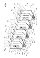
- the machine 100 comprises a plurality of machines 101 which are arranged alongside each other and each of which is equipped with at least one operating device 132, at least one panel 140 which differs from the panel 40 owing to the presence, along at least one of the respective side edges 141, of fastening members 142 of the interlocking or hinged type known and therefore shown only schematically by means of facing rectangles between the corresponding panels arranged alongside each other.
- the machines 1 and 101 differ from each other only in that the panels of the machine 101 are provided with members 142 and therefore it is particularly inexpensive and easy to perform conversion of a machine 1 into a machine 101 for a multi-station 100. Moreover, this confirms the fact already discussed, where the presence of the panel 40 means that the machine 1 may be used as a sectional module M.
- At least one of the panels 140 has at least one housing 145 which is able to house stably an apparatus which can be powered electrically and which may comprise a scent diffuser or a light source, which may be used for chromotherapy sessions, or a computer, radio or television.
- the multi-station machine 100 as illustrated above may also be regarded as a wall 160 which is equipped with exercise machines 101 which are all identical or by machines 101 of varying types and arranged alongside each other so as to define a training circuit defined by the succession of physical exercise machines, or define physical barriers 160 inside spaces assigned for training, both in order to isolate respective service stations 130 of the various machines 1 and in order to combine together the various modules M so as to form the multi-station machine 100.
- Each panel 140 may be individually formed in accordance with varying specifications and using the most varied combinations of housings 145 and openings 146, which combinations in Figure 6 have been illustrated randomly on purpose.
- the panels 140 are connected together along the sides by means of the fastening members 142 in order to keep the machines 101 at a given distance from each other, while ensuring the free use of the minimum training modules M.
- the panels 140 may be provided with housings 145 and openings 146 which may be occupied by apparatus 149, and, in a similar manner to the panels 40, may be formed as one piece or provided with a plurality of elements which are similar to the sheets 42. Therefore, the panels 140 may be joined together in pairs so that they can be oriented as required in order to define a discontinuous or, selectively, a continuous surface. Moreover, this allows the formation of panels 140 which can be easily adapted to varying spatial requirements and can be maintained easily and at a low cost in the event of damage.
- each operating device 132 is associated with a load group 131 comprising counterweights or of the electrically operated type. If the load group 131 were to be of the gravitational type it would comprise at least one load unit 131 with counterweights and an adjusting device 150 provided with at least one user interface member 151 associated with the load unit 131.
- each module M is associated laterally with at least one other module M by means of fastening members which allow the machine 101 to be arranged alongside in an arrangement which takes into account the space available, while safeguarding the free use of each module M.
- the wall 160 is formed, in plan view, in a given manner, if necessary so as to define a physical barrier inside open or closed spaces, and therefore adapt the respective training circuits to the most varied requirements.
- each machine 101 could comprise a horizontal element 148 which is substantially identical to the element 48 in Figure 2, to be installed on the floor so as to provide, in plan view, visual information as to the contours of the corresponding minimum training module M.
- the element 148 could be mounted on the frame 110 of the machine 100 or if necessary also on a top edge of the panel 140 and hence in a position raised above the zone 120 so as to act as a cover.
- each module M in a manner similar to that described above with reference to the machine 1, it is possible to combine with each module M a cover 148' which is identical to the cover 48' of the machine 1 and bounded by edges 148'a and 148'b which allow each machine 100 to be arranged in given spatial configurations which, for the sake of brevity, need not be further explained.
- each machine 101 comprises a unit 140' - visible in Figure 4 alone - which comprises a panel 140, the respective footplate 148 and indicates the dimensions of the minimum training volume M of the machine 101.
- Figure 7 shows in plan view some examples of lay-outs which may be obtained by combining modules M/machines 101 which are identical to or different from each other. It should be noted that individual panels 140 may be used also to close the spaces comprising a plurality of service stations 130 of machines 1/101 arranged alongside each other, in order to isolate the service stations 130 so that they are neither visible nor accessible, both when these stations 130 are separate from each other, as in the case of Figures 7c and 7d, and when the stations 130 are combined with each other, as shown in Figures 7a and 7b.
- the sheet 140" of larger extension could be mounted in position facing the corresponding service zone 130, assigning implicitly to this sheet 140" the function of delimiting the corresponding module M at the front; at the same time, the sheet 140" of smaller width could be formed so as to house a computer 71 or any other device which can be powered electrically, for example the so-called Wellness Expert manufactured by the Applicant, or a similar device, inside a housing 145 or an opening 146 which is suitably formed.
- the two sheets 140" corresponding to the machine 101 in question could be oriented relative to each other so as to be substantially mutually coplanar or angled depending on the requirements of the space to be furnished, without this being regarded as a constraint on the spatial arrangement of the said sheets 140".
Landscapes
- Health & Medical Sciences (AREA)
- General Health & Medical Sciences (AREA)
- Physical Education & Sports Medicine (AREA)
- Life Sciences & Earth Sciences (AREA)
- Biophysics (AREA)
- Orthopedic Medicine & Surgery (AREA)
- Rehabilitation Tools (AREA)
- Toys (AREA)
- Instructional Devices (AREA)
Applications Claiming Priority (2)
| Application Number | Priority Date | Filing Date | Title |
|---|---|---|---|
| ITRA20030024 | 2003-08-11 | ||
| IT000024A ITRA20030024A1 (it) | 2003-08-11 | 2003-08-11 | Macchina ginnica. |
Publications (2)
| Publication Number | Publication Date |
|---|---|
| EP1506798A2 true EP1506798A2 (de) | 2005-02-16 |
| EP1506798A3 EP1506798A3 (de) | 2005-09-07 |
Family
ID=33561965
Family Applications (1)
| Application Number | Title | Priority Date | Filing Date |
|---|---|---|---|
| EP04018345A Withdrawn EP1506798A3 (de) | 2003-08-11 | 2004-08-03 | Übungsgerät |
Country Status (4)
| Country | Link |
|---|---|
| US (1) | US7901340B2 (de) |
| EP (1) | EP1506798A3 (de) |
| CN (1) | CN1329094C (de) |
| IT (1) | ITRA20030024A1 (de) |
Cited By (2)
| Publication number | Priority date | Publication date | Assignee | Title |
|---|---|---|---|---|
| EP2383021A1 (de) | 2010-04-28 | 2011-11-02 | Technogym S.p.A. | Vorrichtung zur begleitenden Durchführung einer Fitnessübung |
| EP2303414A4 (de) * | 2008-07-25 | 2013-05-22 | Takashi Nishimura | Teilweise intarsiertes laufband |
Families Citing this family (8)
| Publication number | Priority date | Publication date | Assignee | Title |
|---|---|---|---|---|
| US20070049471A1 (en) * | 2005-08-29 | 2007-03-01 | Hsiao-Chung Huang | Waist twisting exercise machine |
| US7520843B1 (en) * | 2006-02-06 | 2009-04-21 | Dan Goddard | Dual lift apparatus |
| BRPI0802479A2 (pt) * | 2008-07-25 | 2010-03-23 | Brudden Equip | equipamento de ginÁstica tipo elÍptico semi-embutido |
| US9409047B2 (en) * | 2013-02-14 | 2016-08-09 | Vitalika Inc | Exercise apparatus |
| EP3115085B1 (de) | 2015-07-10 | 2023-09-27 | Kompan A/S | Fitnesssystem, fitnessanordnung und funktionale fitnesselemente |
| USD972054S1 (en) * | 2018-10-05 | 2022-12-06 | Technogym S.P.A. | Functional exercise frame |
| IT201800011070A1 (en) * | 2018-12-13 | 2020-11-11 | Technogym Spa | Gym machine with easy identification of one or more control devices of this gym machine |
| CN113457105B (zh) * | 2020-03-30 | 2022-09-13 | 乔山健身器材(上海)有限公司 | 具健身选单的智能镜子 |
Family Cites Families (23)
| Publication number | Priority date | Publication date | Assignee | Title |
|---|---|---|---|---|
| FI86032C (fi) * | 1989-02-07 | 1992-07-10 | David Fitness & Medical Ltd Oy | Traeningsanordningssystem. |
| US5853332A (en) * | 1995-08-21 | 1998-12-29 | Briggs; Rick A. | Participatory play structure having discrete play articles |
| US5056779A (en) * | 1990-07-20 | 1991-10-15 | Nautilus Acquisition Corporation | Torso exercise machine with range limiter |
| US5209223A (en) * | 1991-03-20 | 1993-05-11 | Biodex Medical Systems, Inc. | Single chair muscle exercise and rehabilitation apparatus |
| US5375641A (en) * | 1993-05-11 | 1994-12-27 | Good Impressions, Inc. | Modular panel system |
| US5537766A (en) * | 1994-02-17 | 1996-07-23 | Classic Exhibits Inc. | Trade show display panels and display panel systems and methods for interconnecting the display panel systems |
| US5620396A (en) * | 1994-08-22 | 1997-04-15 | Westphal; Mark E. | Toy tunnel structure |
| US5779601A (en) * | 1996-02-02 | 1998-07-14 | Vectra Fitness, Incorporated | Compact multi-station exercise machine |
| US5725459A (en) * | 1996-05-03 | 1998-03-10 | Rexach; Marco L. | Exercise apparatus providing simulated free weight exercises and compact stowage |
| US6910306B2 (en) * | 1996-12-24 | 2005-06-28 | Steelcase Development Corporation | Knock-down portable partition system |
| IT245809Y1 (it) * | 1998-03-13 | 2002-03-26 | Teuco Guzzini Spa | Attrezzatura per esercizi ginnici. |
| US6443877B1 (en) * | 1999-02-11 | 2002-09-03 | Dietrich Hoecht | Compact, multi-choice exercise apparatus |
| CN2428038Y (zh) * | 1999-04-12 | 2001-05-02 | 励致文仪有限公司 | 组合屏风 |
| US6447430B1 (en) * | 2000-02-10 | 2002-09-10 | Nautilus, Inc. | Exercise machine |
| US20020091043A1 (en) * | 2000-12-20 | 2002-07-11 | Rexach Marco L. | Space efficient multi-use exercise apparatus |
| USD457580S1 (en) * | 2001-01-19 | 2002-05-21 | Randall T. Webber | Multi-function exercise apparatus |
| US6740017B2 (en) * | 2001-06-26 | 2004-05-25 | Raul Pino | Indoor walking workout facility |
| DE60105827D1 (de) * | 2001-11-16 | 2004-10-28 | Kristel Combes | Struktur zur Ausübung von Acrobatik und zum Spielen |
| US7070546B1 (en) * | 2002-07-05 | 2006-07-04 | Joseph Grasso | Exercise apparatus including multiple function aspects and small footprint |
| US6984197B2 (en) * | 2002-07-08 | 2006-01-10 | Skylite Corporation | Exercise apparatus |
| WO2005000070A2 (en) * | 2003-05-30 | 2005-01-06 | Ball Douglas C | Work space management system |
| US7094189B2 (en) * | 2003-08-11 | 2006-08-22 | Thomas Fallacaro | Apparatus for fitness stretching |
| US6860836B1 (en) * | 2004-01-13 | 2005-03-01 | Yu Feng Wu | Rock climbing exerciser for indoor use |
-
2003
- 2003-08-11 IT IT000024A patent/ITRA20030024A1/it unknown
-
2004
- 2004-08-03 EP EP04018345A patent/EP1506798A3/de not_active Withdrawn
- 2004-08-06 CN CNB2004100766036A patent/CN1329094C/zh not_active Expired - Lifetime
- 2004-08-10 US US10/915,311 patent/US7901340B2/en active Active
Cited By (4)
| Publication number | Priority date | Publication date | Assignee | Title |
|---|---|---|---|---|
| EP2303414A4 (de) * | 2008-07-25 | 2013-05-22 | Takashi Nishimura | Teilweise intarsiertes laufband |
| EP2383021A1 (de) | 2010-04-28 | 2011-11-02 | Technogym S.p.A. | Vorrichtung zur begleitenden Durchführung einer Fitnessübung |
| US8911328B2 (en) | 2010-04-28 | 2014-12-16 | Technogym S.P.A. | Apparatus for the assisted performance of a fitness exercise |
| US9061170B2 (en) | 2010-04-28 | 2015-06-23 | Technogym S.P.A. | Apparatus for the assisted performance of a fitness exercise |
Also Published As
| Publication number | Publication date |
|---|---|
| US7901340B2 (en) | 2011-03-08 |
| US20050070407A1 (en) | 2005-03-31 |
| ITRA20030024A1 (it) | 2005-02-12 |
| CN1644231A (zh) | 2005-07-27 |
| CN1329094C (zh) | 2007-08-01 |
| EP1506798A3 (de) | 2005-09-07 |
Similar Documents
| Publication | Publication Date | Title |
|---|---|---|
| US7901340B2 (en) | Exercising machine | |
| US8029418B2 (en) | Partly-inlaid treadmill | |
| US8641535B2 (en) | Gaming machine cabinet construction and method | |
| US20080293470A1 (en) | Electronic outdoor game apparatus | |
| US6008784A (en) | Electronic display with curved face | |
| EP1163936A2 (de) | Mit Trainingsmitteln ausgestatteter Fussboden | |
| GB0414941D0 (en) | Gaming machine with a translatable flat panel display | |
| CN112824619A (zh) | 智能墙 | |
| CN87101770A (zh) | 多用途棋盘 | |
| US5242341A (en) | Electric climbing training device | |
| CN203591582U (zh) | 一种多功能发牌机 | |
| Lund et al. | Modularity for modulating exercises and levels-observations from cardiac, stroke, and COLD patients therapy | |
| MX2011000220A (es) | Equipo eliptico de gimnasia parcialmente empotrado. | |
| JP3533462B2 (ja) | 多缶ボイラ装置 | |
| CN215781380U (zh) | 一种羽毛球步伐训练指示器 | |
| KR200396991Y1 (ko) | 런닝머신 및 벤치프레스기구 겸용 헬스기구 | |
| CN212998174U (zh) | 一种体育健身用拉伸器材 | |
| JP2015107211A (ja) | 多人数用ロッカー | |
| CN111789996B (zh) | 家具元件和用于对家具元件的隔室进行卫生处理的方法 | |
| WO2024080958A1 (en) | A table structure | |
| KR200325250Y1 (ko) | 런닝머신 | |
| WO2026090697A1 (pt) | Sistema modular para treinamento | |
| Kroll | Structural and Functional Consideration in Designing the Facility: Part II | |
| KR200326192Y1 (ko) | 2중 지붕구조로 된 간이화장실 | |
| RU46437U1 (ru) | Корпус игрового автомата |
Legal Events
| Date | Code | Title | Description |
|---|---|---|---|
| PUAI | Public reference made under article 153(3) epc to a published international application that has entered the european phase |
Free format text: ORIGINAL CODE: 0009012 |
|
| AK | Designated contracting states |
Kind code of ref document: A2 Designated state(s): AT BE BG CH CY CZ DE DK EE ES FI FR GB GR HU IE IT LI LU MC NL PL PT RO SE SI SK TR |
|
| AX | Request for extension of the european patent |
Extension state: AL HR LT LV MK |
|
| PUAL | Search report despatched |
Free format text: ORIGINAL CODE: 0009013 |
|
| AK | Designated contracting states |
Kind code of ref document: A3 Designated state(s): AT BE BG CH CY CZ DE DK EE ES FI FR GB GR HU IE IT LI LU MC NL PL PT RO SE SI SK TR |
|
| AX | Request for extension of the european patent |
Extension state: AL HR LT LV MK |
|
| 17P | Request for examination filed |
Effective date: 20060301 |
|
| AKX | Designation fees paid |
Designated state(s): AT BE BG CH CY CZ DE DK EE ES FI FR GB GR HU IE IT LI LU MC NL PL PT RO SE SI SK TR |
|
| 17Q | First examination report despatched |
Effective date: 20071214 |
|
| STAA | Information on the status of an ep patent application or granted ep patent |
Free format text: STATUS: THE APPLICATION IS DEEMED TO BE WITHDRAWN |
|
| 18D | Application deemed to be withdrawn |
Effective date: 20080425 |