EP1505717A1 - Rotatingly driving device of construction machinery - Google Patents
Rotatingly driving device of construction machinery Download PDFInfo
- Publication number
- EP1505717A1 EP1505717A1 EP03725634A EP03725634A EP1505717A1 EP 1505717 A1 EP1505717 A1 EP 1505717A1 EP 03725634 A EP03725634 A EP 03725634A EP 03725634 A EP03725634 A EP 03725634A EP 1505717 A1 EP1505717 A1 EP 1505717A1
- Authority
- EP
- European Patent Office
- Prior art keywords
- electric motor
- driving device
- construction machine
- hydraulic
- emulation model
- Prior art date
- Legal status (The legal status is an assumption and is not a legal conclusion. Google has not performed a legal analysis and makes no representation as to the accuracy of the status listed.)
- Withdrawn
Links
- 238000010276 construction Methods 0.000 title claims abstract description 21
- 239000003990 capacitor Substances 0.000 claims description 3
- 238000000034 method Methods 0.000 description 8
- 230000004044 response Effects 0.000 description 8
- 230000004043 responsiveness Effects 0.000 description 8
- 230000009467 reduction Effects 0.000 description 7
- 230000008859 change Effects 0.000 description 4
- 230000035939 shock Effects 0.000 description 4
- 230000001133 acceleration Effects 0.000 description 3
- 108010066278 cabin-4 Proteins 0.000 description 2
- 230000000052 comparative effect Effects 0.000 description 1
- 230000000694 effects Effects 0.000 description 1
- 230000005489 elastic deformation Effects 0.000 description 1
- 230000005611 electricity Effects 0.000 description 1
- 230000005484 gravity Effects 0.000 description 1
- 230000010354 integration Effects 0.000 description 1
- 230000007246 mechanism Effects 0.000 description 1
- 230000008685 targeting Effects 0.000 description 1
- 238000011144 upstream manufacturing Methods 0.000 description 1
Images




Classifications
-
- E—FIXED CONSTRUCTIONS
- E02—HYDRAULIC ENGINEERING; FOUNDATIONS; SOIL SHIFTING
- E02F—DREDGING; SOIL-SHIFTING
- E02F9/00—Component parts of dredgers or soil-shifting machines, not restricted to one of the kinds covered by groups E02F3/00 - E02F7/00
- E02F9/08—Superstructures; Supports for superstructures
- E02F9/10—Supports for movable superstructures mounted on travelling or walking gears or on other superstructures
- E02F9/12—Slewing or traversing gears
- E02F9/121—Turntables, i.e. structure rotatable about 360°
- E02F9/123—Drives or control devices specially adapted therefor
-
- E—FIXED CONSTRUCTIONS
- E02—HYDRAULIC ENGINEERING; FOUNDATIONS; SOIL SHIFTING
- E02F—DREDGING; SOIL-SHIFTING
- E02F9/00—Component parts of dredgers or soil-shifting machines, not restricted to one of the kinds covered by groups E02F3/00 - E02F7/00
- E02F9/08—Superstructures; Supports for superstructures
- E02F9/10—Supports for movable superstructures mounted on travelling or walking gears or on other superstructures
- E02F9/12—Slewing or traversing gears
- E02F9/121—Turntables, i.e. structure rotatable about 360°
- E02F9/128—Braking systems
-
- E—FIXED CONSTRUCTIONS
- E02—HYDRAULIC ENGINEERING; FOUNDATIONS; SOIL SHIFTING
- E02F—DREDGING; SOIL-SHIFTING
- E02F9/00—Component parts of dredgers or soil-shifting machines, not restricted to one of the kinds covered by groups E02F3/00 - E02F7/00
- E02F9/20—Drives; Control devices
- E02F9/22—Hydraulic or pneumatic drives
- E02F9/2221—Control of flow rate; Load sensing arrangements
-
- H—ELECTRICITY
- H02—GENERATION; CONVERSION OR DISTRIBUTION OF ELECTRIC POWER
- H02P—CONTROL OR REGULATION OF ELECTRIC MOTORS, ELECTRIC GENERATORS OR DYNAMO-ELECTRIC CONVERTERS; CONTROLLING TRANSFORMERS, REACTORS OR CHOKE COILS
- H02P23/00—Arrangements or methods for the control of AC motors characterised by a control method other than vector control
- H02P23/16—Controlling the angular speed of one shaft
Definitions
- the present invention relates to a rotation driving device for a construction machine, which uses an electric motor to drive a rotational system.
- a hydraulic actuator is extensively adapted, in general, as an actuator of a construction machine.
- a hydraulic driving system using the hydraulic actuator has a low energy efficiency due to generation of resistance in a control valve for controlling the direction and flow rate of pressure oil discharged from a hydraulic pump, generation of a pressure loss in pipes, generation of an excessive flow in a circuit and the like.
- the electric motor is used as a rotating motor for rotating an upper rotating body.
- model follow-up control that is a known technique can be applied.
- This technique comprises controlling the actuator, for example, by use of a normal model such as a primary delay, which can provide an intended responsiveness, so as to follow up the responsiveness of the normal model.
- an object of the present invention is to provide a rotation driving device for a construction machine for driving a rotational system by use of an electric motor, which can mildly respond to operation of a lever in an intermediate range, and swiftly respond to a quick operation of the lever.
- the present invention provides a rotation driving device for a construction machine comprising an electric motor for driving a rotational system of the construction machine, an operating member for instructing an operation of the electric motor, and a controller for controlling the electric motor according to an operation command from the operating member, wherein the controller has an emulation model for simulating dynamic characteristics of a hydraulic rotation driving device in real time, and a control target value as target value for control is calculated from the emulation model according to the operation command from the operating member to control the electric motor.
- the controller when the operating member is operated, the controller simulates, as dynamic characteristics of the hydraulic rotation driving device, for example, revolving speed or driving torque, or the both thereof in real time in reference to the emulation model to compute the control target value.
- the controller controls the electric motor, targeting for the control target value, for example, by speed control or torque control, or the both thereof. Accordingly to this, even in case of driving the rotational system by the electric motor, the responsiveness to the operation of the operating member can be made almost equal to that in the hydraulic driving system.
- the emulation model preferably has specifications of a hydraulic pump, a hydraulic actuator and various valves as hydraulic equipment individually.
- an input unit is preferably connected to the controller, so that each specification in the emulation model can be changed through the input unit. Accordingly to this, the operability can be tuned delicately according to an operator's taste.
- the emulation model preferably has nonlinear characteristic of a flow control valve or pressure control valve as a valve.
- This nonlinear characteristic enables generation of a proper response delay, in case of operating a lever as an operating member in an intermediate range, to prevent generation of hunting, swing-back or shock, and also enables a quick acceleration or quick stopping, in case of quickly operating the lever, without almost generating a response delay.
- any one or two or more of an external power source, a built-in battery, an electric motor driven by an engine, and a capacitor are selected.
- the construction machine may have, as the rotational system, concretely, at least one of a rotating system with a rotating motor as driving source, a hoisting system with a winch motor as driving source, and a traveling system with a traveling motor as driving source.
- Fig. 1 shows a hydraulic excavator as a construction machine to which an actuator driving device of the present invention is applied.
- the hydraulic excavator comprises an upper rotating body 2 mounted on a lower traveling body 1, and the upper rotating body 2 is adapted to be rotatable around a rotating axis R.A.
- a front attachment 3 is provided on the front part of the upper rotating body 2.
- the front attachment 3 comprises a boom 3a, a boom cylinder 3b for raising and lowering the boom 3a, an arm 3c, an arm cylinder 3d for rotating the arm 3c, a bucket 3e and a bucket cylinder 3f for rotating the bucket 3e.
- a cabin 4 is disposed on the left side of the base end of the front attachment 3.
- An engine, hydraulic equipment, a tank and the like (not shown) are disposed in the rear of the cabin 4, and covered with an equipment cover 5.
- Denoted at 6 is an electric motor for rotating the upper rotating body 2, which is composed of an AC servomotor.
- the electric motor 6 may be composed of a DC servomotor.
- the electric motor 6 is used as the driving source of a rotating mechanism (rotating system) for rotating the upper rotating body 2.
- Fig. 2 shows the configuration of a rotation driving device unit on the hydraulic excavator.
- a reduction gear 7 is connected to the output shaft of the electric motor 6, and an inertial load (concretely, a rotator, a winch, a traveling body or the like as a rotational system) 8 is connected to the rotating shaft of the reduction gear 7.
- a controller 9 is adapted so as to give a revolution signal to an inverter 10a.
- the inverter 10a controls a rotation of the electric motor 6, and an encoder 11 detects the revolution of the electric motor 6, and feeds the detected revolution back to the controller 9 as a signal.
- Denoted at 12 is a control lever (operating member) , which is to be operated by an operator to control the revolving speed of the electric motor 6.
- a generator 13a driven by an engine 13, a battery 14, a capacitor 15 and the like are used in combination.
- Denoted at 16a is a converter for converting alternating current to direct current
- 16b and 16c are DC-DC converters for increasing or lowering the voltage.
- the configuration is adapted to mount the generator 13 on the hydraulic excavator and store electricity in the battery 14.
- the configuration can be adapted to receive supply of electric power from an external power source.
- Denoted at 3b is the boom cylinder, which is shown as one actuator of the front attachment 3.
- Denoted at 17 is a hydraulic pump for supplying pressure oil to the boom cylinder 3b, and 18 is the other electric motor for driving the hydraulic pump 17.
- Denoted at 19 is a hydraulic circuit for adjusting the speed and pressure of the boom cylinder 3b, and 10b is an inverter.
- the boom cylinder 3b is driven by the pressure oil supplied from the hydraulic circuit 19. Accordingly, the other electric motor 18 is not adapted to drive the rotational system.
- the controller 9 computes or calculates, on receipt of a manipulated variable S of a control lever 12, an actuator revolving speed ⁇ a in case of a hydraulic driving system with the manipulated variable given by use of a hydraulic driving system emulation model 9a stored therein.
- a speed target value ⁇ ref of the electric motor is determined from the computed revolving speed ⁇ a by use of the following equation.
- ⁇ ref ⁇ a ⁇ N 1 /N 2 wherein N 1 is the speed reduction ratio of the electric motor system, and N 2 is the speed reduction ratio of the hydraulic system.
- the emulation model mainly comprises a hydraulic pump 20, a hydraulic motor 21, a reduction gear 22 connected to the output shaft of the hydraulic motor 21, a rotating inertia 23 connected to the rotating shaft of the reduction gear 22, a control valve 24 for supplying the pressure oil discharged from the hydraulic pump 20 to the hydraulic motor 21 while controlling its flow rate and direction, a main relief valve 25, port relief valves 26a, 26b, check valves 27a and 27b, and a bypass valve 28.
- This figure shows a principal view for normally rotating the hydraulic motor 21.
- the control valve 24 comprises a bleed-off valve (B/O) 29, a meter-in valve (M/I) 30, and a meter-out valve (M/O) 31.
- B/O bleed-off valve
- M/I meter-in valve
- M/O meter-out valve
- Denoted at 32 is a tank.
- a bleed-off opening (the curve shown by B/O of the same figure) is throttled as the lever manipulated variable S becomes larger.
- J L inertial moment of load
- P pressure
- Q flow rate
- K oil volume elasticity
- V pipe inner capacity
- A area
- L length
- C v flow coefficient
- ⁇ oil specific gravity
- ⁇ friction coefficient of pipe
- D pipe diameter
- S lever manipulated variable
- N reduction ratio of speed
- q hydraulic motor capacity
- c check valve
- r port relief valve
- rp main relief valve
- pi pipe part
- hydraulic pump flow rate Q p is given to the equation (5).
- hydraulic motor capacity q is given to the equation (2).
- a numerical integration method for example, the Newmark- ⁇ method is applied to the system of these governing equations, whereby time history response operation is carried out.
- Fig. 5 shows, as a comparative example, a conventional general control method for determining a speed target value to the lever manipulated variable by use of a map 9c to perform a speed feedback control.
- the revolving speed ⁇ of the electric motor 6 also changes steeply to make the responsiveness too sensitive. Consequently, hunting, swing-back in stopping, or shock is generated to deteriorate the operability.
- control is performed so as to simulate the dynamic characteristic of the hydraulic driving device by use of the emulation model.
- the speed target value ⁇ ref draws a waveform as simulates the delay characteristic peculiar to the hydraulic driving device to the lever operation as shown in Fig. 8.
- the electric motor 6 mildly responds to a lever operation in the intermediate range, while the electric motor 6 can be made to rapidly respond to a quick lever operation.
- the target rotating speed ⁇ ref is compared with the rotating speed ⁇ outputted from the encoder 11.
- toques can be mutually compared by use of a hydraulic driving system emulation model 9a' shown in Fig. 11.
- a current target value i ref which is obtained by converting the torque target value ⁇ ref to current value is compared with current i determined from the inverter 10a.
- a switch or touch panel as the input unit may be connected to the controller 9, so that the specification of, for example, the control valve 24 in the emulation model can be properly changed by switching operation of the switch, an operation on the touch panel, or a change of software.
- Such a changeable configuration enables an operator to easily change the characteristic of the operability according to the operator's taste.
- the present invention is useful for a construction machine for driving a rotational system by an electric motor, and particularly suitable for a construction machine in which responsiveness equal to a hydraulic driving system is required for the responsiveness of an actuator to a lever operation.
Landscapes
- Engineering & Computer Science (AREA)
- Mining & Mineral Resources (AREA)
- Civil Engineering (AREA)
- General Engineering & Computer Science (AREA)
- Structural Engineering (AREA)
- Physics & Mathematics (AREA)
- Power Engineering (AREA)
- Fluid Mechanics (AREA)
- Operation Control Of Excavators (AREA)
- Fluid-Pressure Circuits (AREA)
- Servomotors (AREA)
- Control Of Electric Motors In General (AREA)
- Jib Cranes (AREA)
Abstract
In a construction machine comprising an electric motor
6 for driving a rotational system, an operating member for
instructing an operation of the electric motor 6, and a
controller 9 for controlling the electric motor 6 according to
an operation command from the operating member, the controller
9 has an emulation model 9a for simulating dynamic
characteristics of a hydraulic rotation driving device in real
time, and a target value for control is calculated from the
emulation model 9a according to the operation command from the
operating member to control the electric motor 6. Accordingly,
the electric motor can mildly respond to the operation of a lever
in an intermediate range and swiftly respond to a quick
operation of the lever.
Description
- The present invention relates to a rotation driving device for a construction machine, which uses an electric motor to drive a rotational system.
- Conventionally, a hydraulic actuator is extensively adapted, in general, as an actuator of a construction machine. However, a hydraulic driving system using the hydraulic actuator has a low energy efficiency due to generation of resistance in a control valve for controlling the direction and flow rate of pressure oil discharged from a hydraulic pump, generation of a pressure loss in pipes, generation of an excessive flow in a circuit and the like.
- In order to enhance the energy efficiency, thus, it is known to use an electric motor as the actuator.
- In a "turning drive device for construction machine" described in Japanese Patent Application Laid-Open No. 2001-11897, for example, the electric motor is used as a rotating motor for rotating an upper rotating body.
- However, in the use of the electric motor as the actuator of the construction machine, responsiveness of the actuator to a lever operation becomes too sensitive, compared with the hydraulic driving system, although the energy efficiency can be improved.
- When the lever is operated in an intermediate range to change the speed of the electric motor, for example, the electric motor is suddenly changed in speed, consequently causing hunting or shock.
- In case of driving a front attachment by use of the electric motor, a sudden stop of the electric motor might cause elastic deformation of the attachment, which in turn leads to a swing-back. In this way, such an excessive sensitive responsiveness of the actuator to the drive of the electric motor inconveniently deteriorates the operability rather than in the hydraulic driving system.
- To solve such a problem, model follow-up control that is a known technique can be applied. This technique comprises controlling the actuator, for example, by use of a normal model such as a primary delay, which can provide an intended responsiveness, so as to follow up the responsiveness of the normal model.
- However, in such a general model follow-up control, a fixed response delay regularly appears to a lever operation because a linear model such as a simple primary delay is used as the normal model. Consequently, there still remains the problem that a delay also accompanies a sudden operation, which disables a quick acceleration or quick stopping.
- Further, in such a simple linear model, the operability cannot be delicately tuned according to an operator's taste.
- The present invention has been attained considering the problems in a conventional actuator driving device as described above. Accordingly, an object of the present invention is to provide a rotation driving device for a construction machine for driving a rotational system by use of an electric motor, which can mildly respond to operation of a lever in an intermediate range, and swiftly respond to a quick operation of the lever.
- The present invention provides a rotation driving device for a construction machine comprising an electric motor for driving a rotational system of the construction machine, an operating member for instructing an operation of the electric motor, and a controller for controlling the electric motor according to an operation command from the operating member, wherein the controller has an emulation model for simulating dynamic characteristics of a hydraulic rotation driving device in real time, and a control target value as target value for control is calculated from the emulation model according to the operation command from the operating member to control the electric motor.
- According to the present invention, when the operating member is operated, the controller simulates, as dynamic characteristics of the hydraulic rotation driving device, for example, revolving speed or driving torque, or the both thereof in real time in reference to the emulation model to compute the control target value. The controller then controls the electric motor, targeting for the control target value, for example, by speed control or torque control, or the both thereof. Accordingly to this, even in case of driving the rotational system by the electric motor, the responsiveness to the operation of the operating member can be made almost equal to that in the hydraulic driving system.
- In the present invention, the emulation model preferably has specifications of a hydraulic pump, a hydraulic actuator and various valves as hydraulic equipment individually.
- In the present invention, an input unit is preferably connected to the controller, so that each specification in the emulation model can be changed through the input unit. Accordingly to this, the operability can be tuned delicately according to an operator's taste.
- In the present invention, the emulation model preferably has nonlinear characteristic of a flow control valve or pressure control valve as a valve.
- This nonlinear characteristic enables generation of a proper response delay, in case of operating a lever as an operating member in an intermediate range, to prevent generation of hunting, swing-back or shock, and also enables a quick acceleration or quick stopping, in case of quickly operating the lever, without almost generating a response delay.
- In the present invention, as the power source of the construction machine, any one or two or more of an external power source, a built-in battery, an electric motor driven by an engine, and a capacitor are selected.
- In the present invention, the construction machine may have, as the rotational system, concretely, at least one of a rotating system with a rotating motor as driving source, a hoisting system with a winch motor as driving source, and a traveling system with a traveling motor as driving source.
-
- Fig. 1 is an apparent view of a hydraulic excavator to which a rotation driving device of the present invention is applied;
- Fig. 2 is an illustrative view showing the configuration of the rotation driving device of the present invention;
- Fig. 3 is an illustrative view showing a control flow according to the present invention;
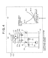
- Fig. 4 comprises (a) and (b) which are a circuit view showing the configuration of an emulation model shown in Fig. 3, and a table showing each valve characteristic in the same model, respectively;
- Fig. 5 is an illustrative view showing a conventional control flow;
- Fig. 6 is a graph showing one example of an operation pattern by a conventional control;
- Fig. 7 is a graph showing the speed response waveform of an electric motor by the conventional control;
- Fig. 8 is a graph showing the speed response characteristic of the electric motor by the control according to the present invention;
- Fig. 9 is a graph showing another example of the operation pattern by a control lever;
- Fig. 10 is a graph showing the speed response characteristic of the electric motor according to the present invention to the operation pattern of Fig. 9; and
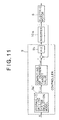
- Fig. 11 is an illustrative view showing another control flow according to the present invention.
-
- The present invention will be described below in detail based on preferred embodiments shown in the drawings.
- Fig. 1 shows a hydraulic excavator as a construction machine to which an actuator driving device of the present invention is applied.
- In this figure, the hydraulic excavator comprises an upper rotating body 2 mounted on a lower traveling body 1, and the upper rotating body 2 is adapted to be rotatable around a rotating axis R.A.
- A front attachment 3 is provided on the front part of the upper rotating body 2. The front attachment 3 comprises a boom 3a, a boom cylinder 3b for raising and lowering the boom 3a, an arm 3c, an arm cylinder 3d for rotating the arm 3c, a bucket 3e and a bucket cylinder 3f for rotating the bucket 3e.
- A cabin 4 is disposed on the left side of the base end of the front attachment 3. An engine, hydraulic equipment, a tank and the like (not shown) are disposed in the rear of the cabin 4, and covered with an equipment cover 5.
- Denoted at 6 is an electric motor for rotating the upper rotating body 2, which is composed of an AC servomotor. The electric motor 6 may be composed of a DC servomotor. The electric motor 6 is used as the driving source of a rotating mechanism (rotating system) for rotating the upper rotating body 2.
- Fig. 2 shows the configuration of a rotation driving device unit on the hydraulic excavator.
- A reduction gear 7 is connected to the output shaft of the electric motor 6, and an inertial load (concretely, a rotator, a winch, a traveling body or the like as a rotational system) 8 is connected to the rotating shaft of the reduction gear 7.
- A controller 9 is adapted so as to give a revolution signal to an inverter 10a. The inverter 10a controls a rotation of the electric motor 6, and an encoder 11 detects the revolution of the electric motor 6, and feeds the detected revolution back to the controller 9 as a signal.
- Denoted at 12 is a control lever (operating member) , which is to be operated by an operator to control the revolving speed of the electric motor 6.
- As a power supplying source for driving the electric motor 6, a generator 13a driven by an engine 13, a battery 14, a capacitor 15 and the like are used in combination. Denoted at 16a is a converter for converting alternating current to direct current, and 16b and 16c are DC-DC converters for increasing or lowering the voltage.
- In this embodiment, the configuration is adapted to mount the generator 13 on the hydraulic excavator and store electricity in the battery 14. However, the configuration can be adapted to receive supply of electric power from an external power source.
- Denoted at 3b is the boom cylinder, which is shown as one actuator of the front attachment 3.
- Denoted at 17 is a hydraulic pump for supplying pressure oil to the boom cylinder 3b, and 18 is the other electric motor for driving the hydraulic pump 17. Denoted at 19 is a hydraulic circuit for adjusting the speed and pressure of the boom cylinder 3b, and 10b is an inverter.
- The boom cylinder 3b is driven by the pressure oil supplied from the hydraulic circuit 19. Accordingly, the other electric motor 18 is not adapted to drive the rotational system.
- A control flow in the controller 9 will be described in reference to Fig. 3.
- The controller 9 computes or calculates, on receipt of a manipulated variable S of a control lever 12, an actuator revolving speed ωa in case of a hydraulic driving system with the manipulated variable given by use of a hydraulic driving system emulation model 9a stored therein.
- A speed target value ωref of the electric motor is determined from the computed revolving speed ωa by use of the following equation.
- By using this ωref as the speed target value of the electric motor 6, PID control is carried out by a PID 9b followed by comparison with the revolving speed ω determined from the encoder 11, whereby speed feedback control is carried out.
- The content of the hydraulic driving system emulation model is shown in Fig. 4(a).
- In Fig. 4(a), the emulation model mainly comprises a hydraulic pump 20, a hydraulic motor 21, a reduction gear 22 connected to the output shaft of the hydraulic motor 21, a rotating inertia 23 connected to the rotating shaft of the reduction gear 22, a control valve 24 for supplying the pressure oil discharged from the hydraulic pump 20 to the hydraulic motor 21 while controlling its flow rate and direction, a main relief valve 25, port relief valves 26a, 26b, check valves 27a and 27b, and a bypass valve 28. This figure shows a principal view for normally rotating the hydraulic motor 21.
- The control valve 24 comprises a bleed-off valve (B/O) 29, a meter-in valve (M/I) 30, and a meter-out valve (M/O) 31. Denoted at 32 is a tank.
- In the emulation model, as shown in Fig. 4 (b), a bleed-off opening (the curve shown by B/O of the same figure) is throttled as the lever manipulated variable S becomes larger. Contrary to this, a meter-in opening (the curve shown by M/I of the same figure) and a meter-out opening (the curve shown by M/O of the same figure) are opened. Consequently, the pressure oil flow rate to be supplied to the hydraulic motor 21 is increased.
- The governing equations of this emulation model are shown below.
- Wherein JL: inertial moment of load, P: pressure, Q: flow rate, K: oil volume elasticity, V: pipe inner capacity, A: area, L: length, Cv: flow coefficient, γ: oil specific gravity, λ: friction coefficient of pipe, D: pipe diameter, S: lever manipulated variable, N: reduction ratio of speed, q: hydraulic motor capacity, c; check valve, r: port relief valve, rp: main relief valve, pi: pipe part, 1: upstream side, and 2: downstream side.
- In the above equations, as the specification of the hydraulic pump 20 that is the hydraulic pressure source, hydraulic pump flow rate Qp is given to the equation (5).
- As the characteristic of the actuator, hydraulic motor capacity q is given to the equation (2).
- As the characteristic of the control valve 24, the relation of each opening area Abo, Ami, Amo of the bleed-off valve 29, meter-in valve 30, and meter-out valve respectively constituting the control valve 24 with the lever manipulated variable S is given to the equation (6).
- In the emulation model of this embodiment, a numerical integration method, for example, the Newmark-β method is applied to the system of these governing equations, whereby time history response operation is carried out.
- The operation of the emulation model will be described in reference to Figs. 5-10.
- Fig. 5 shows, as a comparative example, a conventional general control method for determining a speed target value to the lever manipulated variable by use of a map 9c to perform a speed feedback control.
- In this case, as shown in the operation example of Fig. 6, the lever is operated stepwise in an intermediate range, the speed target value ωref changes steeply relative to the lever operation as shown in Fig. 7.
- Therefore, the revolving speed ω of the electric motor 6 also changes steeply to make the responsiveness too sensitive. Consequently, hunting, swing-back in stopping, or shock is generated to deteriorate the operability.
- In contrast to this, in the control method of this embodiment, the control is performed so as to simulate the dynamic characteristic of the hydraulic driving device by use of the emulation model.
- Accordingly, when the lever is operated stepwise in the intermediate range, the speed target value ωref draws a waveform as simulates the delay characteristic peculiar to the hydraulic driving device to the lever operation as shown in Fig. 8.
- Consequently, the speed change of the electric motor 6 to the lever operation is moderated (refer to ω of the graph) , and the operability can be improved without causing the hunting, swing-back in stoppage, or shock.
- On the other hand, in case of a quick accelerating or quick decelerating operation, the response delay appears in a conventional model follow-up control using primary delay, as shown in Fig. 10, similarly to the lever operation in the intermediate range (refer to L1).
- In contrast, in the control method of this embodiment, since the relief valves 26a, 26b (refer to Fig. 4 (a) ) for keeping the circuit pressure constant are included in the emulation model, acceleration and deceleration are carried out at the maximum torque similarly to the case of the hydraulic driving device (refer to L2) .
- According to the control method of this embodiment, thus, the electric motor 6 mildly responds to a lever operation in the intermediate range, while the electric motor 6 can be made to rapidly respond to a quick lever operation.
- In the emulation model described above, the target rotating speed ωref is compared with the rotating speed ω outputted from the encoder 11. However, without being limited to this, toques can be mutually compared by use of a hydraulic driving system emulation model 9a' shown in Fig. 11.
- Namely, the driving torque of the hydraulic actuator with a lever manipulated variable given is as follows:
- The same effect as the above embodiment can be obtained by performing a feedback control using the control rule of the PID control with the τref as the torque target value of the electric motor 6. Concretely, a current target value iref, which is obtained by converting the torque target value τref to current value is compared with current i determined from the inverter 10a.
- A switch or touch panel as the input unit may be connected to the controller 9, so that the specification of, for example, the control valve 24 in the emulation model can be properly changed by switching operation of the switch, an operation on the touch panel, or a change of software.
- Such a changeable configuration enables an operator to easily change the characteristic of the operability according to the operator's taste.
- The present invention is useful for a construction machine for driving a rotational system by an electric motor, and particularly suitable for a construction machine in which responsiveness equal to a hydraulic driving system is required for the responsiveness of an actuator to a lever operation.
Claims (6)
- A rotation driving device for a construction machine comprising an electric motor for driving a rotational system of said construction machine, an operating member for instructing an operation of said electric motor, and a controller for controlling said electric motor according to an operation command from said operating member,
wherein said controller has an emulation model for simulating dynamic characteristics of a hydraulic rotational driving device in real time, and a target value for control is calculated by use of said emulation model according to the operation command from said operating member to control said electric motor. - The rotation driving device for the construction machine according to claim 1, wherein said emulation model individually has specifications of a hydraulic pump, a hydraulic actuator and various valves as hydraulic equipment.
- The rotation driving device for the construction machine according to claim 2, wherein an input unit is connected to said controller, so that each of said specifications in said emulation model is changed through said input unit.
- The rotation driving device for the construction machine according to claim 2, wherein said emulation model has nonlinear characteristic of a flow control valve or pressure control valve as said valve.
- The rotation driving device for the construction machine according to claim 1, wherein either one or two or more of an external power source, a built-in battery, a generator driven by an engine and a capacitor are selected as a power source of said electric motor.
- The rotation driving device for the construction machine according to claim 1, wherein said rotational system includes at least one of a rotating system having a rotating motor as driving source, a hoisting system with a winch motor as driving source, and a traveling system with a traveling motor as driving source.
Applications Claiming Priority (3)
| Application Number | Priority Date | Filing Date | Title |
|---|---|---|---|
| JP2002136967A JP4099006B2 (en) | 2002-05-13 | 2002-05-13 | Rotation drive device for construction machinery |
| JP2002136967 | 2002-05-13 | ||
| PCT/JP2003/005138 WO2003096522A1 (en) | 2002-05-13 | 2003-04-23 | Rotatingly driving device of construction machinery |
Publications (1)
| Publication Number | Publication Date |
|---|---|
| EP1505717A1 true EP1505717A1 (en) | 2005-02-09 |
Family
ID=29416801
Family Applications (1)
| Application Number | Title | Priority Date | Filing Date |
|---|---|---|---|
| EP03725634A Withdrawn EP1505717A1 (en) | 2002-05-13 | 2003-04-23 | Rotatingly driving device of construction machinery |
Country Status (6)
| Country | Link |
|---|---|
| US (1) | US20050237021A1 (en) |
| EP (1) | EP1505717A1 (en) |
| JP (1) | JP4099006B2 (en) |
| KR (1) | KR20050000530A (en) |
| CN (1) | CN1653680A (en) |
| WO (1) | WO2003096522A1 (en) |
Cited By (8)
| Publication number | Priority date | Publication date | Assignee | Title |
|---|---|---|---|---|
| WO2007081277A1 (en) * | 2006-01-16 | 2007-07-19 | Volvo Construction Equipment Ab | Method for controlling a hydraulic machine in a control system |
| WO2007088688A1 (en) | 2006-02-01 | 2007-08-09 | Hitachi Construction Machinery Co., Ltd. | Rotation drive device for construction machine |
| WO2008041892A1 (en) * | 2006-10-06 | 2008-04-10 | Volvo Construction Equipment Ab | A method for operating a working machine and a working machine |
| WO2008041890A1 (en) * | 2006-10-06 | 2008-04-10 | Volvo Construction Equipment Ab | A method for operating a working machine and a working machine with an improved ability to meet transient loads |
| WO2008041891A1 (en) * | 2006-10-06 | 2008-04-10 | Volvo Construction Equipment Ab | A method for operating a working machine and a working machine with an improved transmission line |
| EP1961869A1 (en) * | 2007-02-21 | 2008-08-27 | Kobelco Construction Machinery Co., Ltd. | Rotation control device and working machine therewith |
| WO2009145681A1 (en) * | 2008-05-27 | 2009-12-03 | Volvo Construction Equipment Ab | A method and a system for operating a working machine |
| WO2021247095A1 (en) * | 2020-06-03 | 2021-12-09 | Parker-Hannifin Corporation | Sensing and control of a rapidly-commanded hydraulic actuator |
Families Citing this family (20)
| Publication number | Priority date | Publication date | Assignee | Title |
|---|---|---|---|---|
| US7378808B2 (en) * | 2004-05-25 | 2008-05-27 | Caterpillar Inc. | Electric drive system having DC bus voltage control |
| KR101117533B1 (en) * | 2004-07-05 | 2012-03-08 | 가부시키가이샤 고마쓰 세이사쿠쇼 | Rotation control device, rotation control method, and construction machine |
| JP4788246B2 (en) * | 2005-08-31 | 2011-10-05 | ソニー株式会社 | Input device and input method |
| CN101033748B (en) * | 2006-03-08 | 2013-07-24 | Itt制造企业公司 | Method for determining pump flow without the use of traditional sensors |
| US7925385B2 (en) * | 2006-03-08 | 2011-04-12 | Itt Manufacturing Enterprises, Inc | Method for optimizing valve position and pump speed in a PID control valve system without the use of external signals |
| US7945411B2 (en) | 2006-03-08 | 2011-05-17 | Itt Manufacturing Enterprises, Inc | Method for determining pump flow without the use of traditional sensors |
| US7467514B2 (en) * | 2006-07-17 | 2008-12-23 | Caterpillar Inc. | System and method for controlling shakability of a work tool |
| JP5125048B2 (en) * | 2006-09-29 | 2013-01-23 | コベルコ建機株式会社 | Swing control device for work machine |
| JP4770807B2 (en) * | 2007-07-23 | 2011-09-14 | ダイキン工業株式会社 | Rotating body drive control device |
| JP2010006591A (en) * | 2008-06-30 | 2010-01-14 | Sekigahara Seisakusho:Kk | Crane device for marine vessel |
| JP5062128B2 (en) * | 2008-09-29 | 2012-10-31 | コベルコ建機株式会社 | Swing drive device for work machine |
| KR101112135B1 (en) | 2009-07-28 | 2012-02-22 | 볼보 컨스트럭션 이큅먼트 에이비 | Swing Control System and Method Of Construction Machine Using Electric Motor |
| JP5511316B2 (en) * | 2009-11-02 | 2014-06-04 | 住友建機株式会社 | Excavator swivel control device |
| KR102015141B1 (en) * | 2013-03-29 | 2019-08-27 | 두산인프라코어 주식회사 | Control system and method of Hydraulic Pump for Construction Machinery |
| US9484602B1 (en) | 2013-08-22 | 2016-11-01 | OSC Manufacturing & Equipment Services, Inc. | Light tower having a battery housing |
| JP6362900B2 (en) * | 2014-03-31 | 2018-07-25 | 住友重機械工業株式会社 | Electric swivel device and controller |
| JP6564272B2 (en) * | 2014-08-12 | 2019-08-21 | 株式会社神戸製鋼所 | HIL simulation system and HIL simulation method |
| US10749224B2 (en) | 2015-08-17 | 2020-08-18 | OSC Manufacturing & Equipment Services, Inc. | Rechargeable battery power system having a battery with multiple uses |
| EP3754837B1 (en) * | 2019-06-17 | 2024-01-17 | Schneider Electric Industries SAS | Method for monitoring a machine |
| CN114835019B (en) * | 2022-04-02 | 2025-09-02 | 江苏徐工工程机械研究院有限公司 | Track change control system and rescue crane |
Family Cites Families (11)
| Publication number | Priority date | Publication date | Assignee | Title |
|---|---|---|---|---|
| US5953977A (en) * | 1997-12-19 | 1999-09-21 | Carnegie Mellon University | Simulation modeling of non-linear hydraulic actuator response |
| JP3987199B2 (en) * | 1998-03-31 | 2007-10-03 | マツダ株式会社 | Simulation device, simulation method, and storage medium |
| US6326758B1 (en) * | 1999-12-15 | 2001-12-04 | Reliance Electric Technologies, Llc | Integrated diagnostics and control systems |
| US6464464B2 (en) * | 1999-03-24 | 2002-10-15 | Itt Manufacturing Enterprises, Inc. | Apparatus and method for controlling a pump system |
| JP3877909B2 (en) * | 1999-06-30 | 2007-02-07 | 株式会社神戸製鋼所 | Swivel drive device for construction machinery |
| AU2001253503A1 (en) * | 2000-04-14 | 2001-10-30 | Actuant Corporation | Variable speed hydraulic pump |
| AU2001281851A1 (en) * | 2000-07-17 | 2002-01-30 | Abm Greiffenberger Antriebstechnik Gmbh | Method for sensorless drive control of an electric vehicle and drive control operating according to said method |
| JP2002062230A (en) * | 2000-08-21 | 2002-02-28 | Saginomiya Seisakusho Inc | Load test method |
| JP3529042B2 (en) * | 2000-10-02 | 2004-05-24 | 日産自動車株式会社 | Lane tracking controller |
| US6585041B2 (en) * | 2001-07-23 | 2003-07-01 | Baker Hughes Incorporated | Virtual sensors to provide expanded downhole instrumentation for electrical submersible pumps (ESPs) |
| US6682669B2 (en) * | 2001-09-29 | 2004-01-27 | Van Dorn Demag Corporation | Model predictive control apparatus and methods for motion and/or pressure control of injection molding machines |
-
2002
- 2002-05-13 JP JP2002136967A patent/JP4099006B2/en not_active Expired - Fee Related
-
2003
- 2003-04-23 US US10/512,088 patent/US20050237021A1/en not_active Abandoned
- 2003-04-23 WO PCT/JP2003/005138 patent/WO2003096522A1/en not_active Ceased
- 2003-04-23 CN CNA038109271A patent/CN1653680A/en active Pending
- 2003-04-23 KR KR10-2004-7018238A patent/KR20050000530A/en not_active Abandoned
- 2003-04-23 EP EP03725634A patent/EP1505717A1/en not_active Withdrawn
Non-Patent Citations (1)
| Title |
|---|
| See references of WO03096522A1 * |
Cited By (19)
| Publication number | Priority date | Publication date | Assignee | Title |
|---|---|---|---|---|
| US8240144B2 (en) | 2006-01-16 | 2012-08-14 | Volvo Construction Equipment Ab | Method for controlling a hydraulic machine in a control system |
| WO2007081277A1 (en) * | 2006-01-16 | 2007-07-19 | Volvo Construction Equipment Ab | Method for controlling a hydraulic machine in a control system |
| CN101370988B (en) * | 2006-01-16 | 2011-05-25 | 沃尔沃建筑设备公司 | Method for controlling a hydraulic machine in a control system |
| EP1988221A4 (en) * | 2006-02-01 | 2011-03-02 | Hitachi Construction Machinery | Rotation drive device for construction machine |
| WO2007088688A1 (en) | 2006-02-01 | 2007-08-09 | Hitachi Construction Machinery Co., Ltd. | Rotation drive device for construction machine |
| US7979182B2 (en) | 2006-02-01 | 2011-07-12 | Hitachi Construction Machinery Co., Ltd. | Swing drive system for construction machine |
| US8200400B2 (en) | 2006-10-06 | 2012-06-12 | VolvoConstruction Equipment AB | Method for operating a working machine and a working machine with an improved ability to meet transient loads |
| WO2008041891A1 (en) * | 2006-10-06 | 2008-04-10 | Volvo Construction Equipment Ab | A method for operating a working machine and a working machine with an improved transmission line |
| CN101522997B (en) * | 2006-10-06 | 2011-07-27 | 沃尔沃建筑设备公司 | A method for operating a working machine and a working machine with an improved ability to meet transient loads |
| WO2008041890A1 (en) * | 2006-10-06 | 2008-04-10 | Volvo Construction Equipment Ab | A method for operating a working machine and a working machine with an improved ability to meet transient loads |
| CN101542048B (en) * | 2006-10-06 | 2012-06-13 | 沃尔沃建筑设备公司 | A method for operating a working machine and a working machine |
| WO2008041892A1 (en) * | 2006-10-06 | 2008-04-10 | Volvo Construction Equipment Ab | A method for operating a working machine and a working machine |
| US8447483B2 (en) | 2006-10-06 | 2013-05-21 | Volvo Construction Equipment Ab | Method for operating a working machine and a working machine with an improved transmission line |
| US9032725B2 (en) | 2006-10-06 | 2015-05-19 | Volvo Construction Equipment Ab | Method for operating a working machine and a working machine |
| EP2275606A3 (en) * | 2007-02-21 | 2011-04-06 | Kobelco Construction Machinery Co., Ltd. | Rotation control device and working machine therewith |
| EP1961869A1 (en) * | 2007-02-21 | 2008-08-27 | Kobelco Construction Machinery Co., Ltd. | Rotation control device and working machine therewith |
| WO2009145681A1 (en) * | 2008-05-27 | 2009-12-03 | Volvo Construction Equipment Ab | A method and a system for operating a working machine |
| US8606471B2 (en) | 2008-05-27 | 2013-12-10 | Volvo Construction Equipment Ab | Method and a system for operating a working machine |
| WO2021247095A1 (en) * | 2020-06-03 | 2021-12-09 | Parker-Hannifin Corporation | Sensing and control of a rapidly-commanded hydraulic actuator |
Also Published As
| Publication number | Publication date |
|---|---|
| JP4099006B2 (en) | 2008-06-11 |
| WO2003096522A1 (en) | 2003-11-20 |
| JP2003333876A (en) | 2003-11-21 |
| KR20050000530A (en) | 2005-01-05 |
| US20050237021A1 (en) | 2005-10-27 |
| CN1653680A (en) | 2005-08-10 |
Similar Documents
| Publication | Publication Date | Title |
|---|---|---|
| US20050237021A1 (en) | Rotatingly driving device of construction machinery | |
| JP7058783B2 (en) | Hydraulic drive for electric hydraulic work machines | |
| JP4082935B2 (en) | Hybrid construction machine | |
| JP5203434B2 (en) | Hybrid construction machinery | |
| JP5828481B2 (en) | Construction machine control equipment | |
| KR20100137421A (en) | Hybrid Construction Machine Control | |
| WO2012050028A1 (en) | Construction machine having rotary element | |
| US8538612B2 (en) | Device for controlling hybrid construction machine | |
| KR20110009079A (en) | Hybrid Construction Machine Control | |
| KR20100124721A (en) | Control apparatus of hybrid-construction machine | |
| CA2296156C (en) | Control and hydraulic system for a liftcrane | |
| JP2001011899A (en) | Hydraulic circuit for work machine and hybrid work machine | |
| JP2007205032A (en) | Revolving driving device for construction machine | |
| JP4294086B2 (en) | Electric motor control device | |
| KR20110009149A (en) | Hybrid Construction Machine Control | |
| JP6214327B2 (en) | Hybrid construction machine | |
| JP2004360216A (en) | Swing driving device for construction machinery | |
| JP2010095906A (en) | Construction machine and slewing controlling device | |
| JP2001012418A (en) | Hybrid working machine | |
| JP3594680B2 (en) | Hydraulic regenerator of hydraulic machine | |
| JP2007010064A (en) | Hydraulic control equipment for construction machinery | |
| JP2014141993A (en) | Construction machine hydraulic transmission | |
| JP4725903B2 (en) | Electric motor control device | |
| JP2011001736A (en) | Turning control device for construction machine | |
| JP2001012406A (en) | Hydraulic circuit for working machine and hybrid working machine |
Legal Events
| Date | Code | Title | Description |
|---|---|---|---|
| PUAI | Public reference made under article 153(3) epc to a published international application that has entered the european phase |
Free format text: ORIGINAL CODE: 0009012 |
|
| 17P | Request for examination filed |
Effective date: 20041109 |
|
| AK | Designated contracting states |
Kind code of ref document: A1 Designated state(s): AT BE BG CH CY CZ DE DK EE ES FI FR GB GR HU IE IT LI LU MC NL PT RO SE SI SK TR |
|
| STAA | Information on the status of an ep patent application or granted ep patent |
Free format text: STATUS: THE APPLICATION HAS BEEN WITHDRAWN |
|
| 18W | Application withdrawn |
Effective date: 20060821 |