EP1505604B1 - Positionieranordnung mit Aufsaugungsfilter und Plattenantrieb mit einer solchen Anordnung - Google Patents
Positionieranordnung mit Aufsaugungsfilter und Plattenantrieb mit einer solchen Anordnung Download PDFInfo
- Publication number
- EP1505604B1 EP1505604B1 EP04016588A EP04016588A EP1505604B1 EP 1505604 B1 EP1505604 B1 EP 1505604B1 EP 04016588 A EP04016588 A EP 04016588A EP 04016588 A EP04016588 A EP 04016588A EP 1505604 B1 EP1505604 B1 EP 1505604B1
- Authority
- EP
- European Patent Office
- Prior art keywords
- absorption filter
- actuator
- disk
- swing arm
- airflow
- Prior art date
- Legal status (The legal status is an assumption and is not a legal conclusion. Google has not performed a legal analysis and makes no representation as to the accuracy of the status listed.)
- Expired - Lifetime
Links
Images


Classifications
-
- G—PHYSICS
- G11—INFORMATION STORAGE
- G11B—INFORMATION STORAGE BASED ON RELATIVE MOVEMENT BETWEEN RECORD CARRIER AND TRANSDUCER
- G11B21/00—Head arrangements not specific to the method of recording or reproducing
- G11B21/16—Supporting the heads; Supporting the sockets for plug-in heads
- G11B21/20—Supporting the heads; Supporting the sockets for plug-in heads while the head is in operative position but stationary or permitting minor movements to follow irregularities in surface of record carrier
- G11B21/21—Supporting the heads; Supporting the sockets for plug-in heads while the head is in operative position but stationary or permitting minor movements to follow irregularities in surface of record carrier with provision for maintaining desired spacing of head from record carrier, e.g. fluid-dynamic spacing, slider
-
- G—PHYSICS
- G11—INFORMATION STORAGE
- G11B—INFORMATION STORAGE BASED ON RELATIVE MOVEMENT BETWEEN RECORD CARRIER AND TRANSDUCER
- G11B5/00—Recording by magnetisation or demagnetisation of a record carrier; Reproducing by magnetic means; Record carriers therefor
- G11B5/48—Disposition or mounting of heads or head supports relative to record carriers ; arrangements of heads, e.g. for scanning the record carrier to increase the relative speed
-
- G—PHYSICS
- G11—INFORMATION STORAGE
- G11B—INFORMATION STORAGE BASED ON RELATIVE MOVEMENT BETWEEN RECORD CARRIER AND TRANSDUCER
- G11B33/00—Constructional parts, details or accessories not provided for in the other groups of this subclass
- G11B33/14—Reducing influence of physical parameters, e.g. temperature change, moisture, dust
- G11B33/1446—Reducing contamination, e.g. by dust, debris
- G11B33/146—Reducing contamination, e.g. by dust, debris constructional details of filters
-
- G—PHYSICS
- G11—INFORMATION STORAGE
- G11B—INFORMATION STORAGE BASED ON RELATIVE MOVEMENT BETWEEN RECORD CARRIER AND TRANSDUCER
- G11B25/00—Apparatus characterised by the shape of record carrier employed but not specific to the method of recording or reproducing, e.g. dictating apparatus; Combinations of such apparatus
- G11B25/04—Apparatus characterised by the shape of record carrier employed but not specific to the method of recording or reproducing, e.g. dictating apparatus; Combinations of such apparatus using flat record carriers, e.g. disc, card
- G11B25/043—Apparatus characterised by the shape of record carrier employed but not specific to the method of recording or reproducing, e.g. dictating apparatus; Combinations of such apparatus using flat record carriers, e.g. disc, card using rotating discs
-
- G—PHYSICS
- G11—INFORMATION STORAGE
- G11B—INFORMATION STORAGE BASED ON RELATIVE MOVEMENT BETWEEN RECORD CARRIER AND TRANSDUCER
- G11B33/00—Constructional parts, details or accessories not provided for in the other groups of this subclass
- G11B33/14—Reducing influence of physical parameters, e.g. temperature change, moisture, dust
- G11B33/1446—Reducing contamination, e.g. by dust, debris
Definitions
- the invention relates to a disk drive, and more particularly, to an actuator having an absorption filter absorbing foreign materials in a disk drive and a disk drive having the same.
- HDDs Hard disk drives
- the read/write head performs its functions while being moved by an actuator to a desired position, wherein the read/write head is lifted to a predetermined height from a recording surface of a rotating disk.
- FIG. 1 is a plan view illustrating the configuration of a conventional hard disk drive.
- FIG. 2 is a magnified perspective view illustrating a ramp and a suspension portion of the actuator shown in FIG. 1 .
- a conventional hard disk drive includes a spindle motor 12 installed on a base plate 10.
- a disk 20, which is one or more disks, is installed on the spindle motor 12.
- An actuator 30 is installed to move a read/write head (not shown) for reproducing and recording data to a predetermined position on the disk 20.
- the actuator 30 includes a swing arm 32 rotatably coupled to a pivot bearing 31 installed on the base plate 10, a suspension 33 installed at one end portion of the swing arm 32 and supporting a slider 34, on which the head is mounted, toward a surface of the disk 20 to be elastically biased, and a voice coil motor (VCM) to rotate the swing arm 32.
- the voice coil motor includes a VCM coil 36 coupled to the other end portion of the swing arm 32, a lower yoke 37 installed below the VCM coil 36, and a magnet 38 attached to an upper surface of the lower yoke 37.
- the voice coil motor may further include an upper yoke installed above the VCM coil 36 and a magnet attached to a lower surface of the upper yoke.
- the voice coil motor having the above configuration is controlled by a servo control system to rotate the swing arm 32 in a direction following the Fleming's left hand rule by the interaction between current applied to the VCM coil 36 and a magnetic field formed by the magnet 38. That is, when the power of the hard disk drive is on and the disk 20 starts to rotate in a direction D, the voice coil motor rotates the swing arm 32 counterclockwise, that is, in a direction A, to move the slider 34 on which the head is mounted toward a position above the recording surface of the disk 20.
- the slider 34 is lifted to a predetermined height, for example, about 13 nm, from the surface of the disk 20 by a lift force generated by the rotating disk 20. In this state, the read/write head mounted on the slider 34 reproduces or records data with respect to the recording surface of the disk 20.
- the head parking system may be employed using a contact start stop (CSS) method or a ramp loading method.
- CSS contact start stop
- a parking zone where data is not recorded is provided at or near an inner circumferential side of the disk 20 and the head is parked in the parking zone in a contact or near contact manner.
- a head parking system adopting the CSS method since the parking zone needs to be provided at or near the inner circumferential side of the disk 20, data storage space is reduced.
- a head parking system adopting the ramp loading method is widely used because it can secure a larger data storage space.
- a ramp 40 is installed at the outside of the disk 20 and the head is parked on the ramp 40.
- the suspension 33 has an end-tab 35 extended therefrom, which contacts a support surface 41 of the ramp 40.
- the end-tab 35 generally has a shape convex toward the support surface 41 to reduce a contact area between the end-tab 35 and the support surface 41 of the ramp 40.
- the voice coil motor rotates the swing arm 32 clockwise, (that is, in a direction B). Accordingly, the end-tab 35 is unloaded from the disk 20 and moved to the support surface 41 of the ramp 40. In contrast, when the power of the hard disk drive is on and the disk 20 starts to rotate, the end-tab 35 is unloaded from the support surface 41 of the ramp 40 and moved above the disk 20 by the rotation of the swing arm 32.
- the actuator 30 rotates and moves toward the recording surface of the disk 20 from the ramp 40. In this case, the head contacts the recording surface of the disk 20 so that the read/write head and the recording surface of the disk 20 may be damaged.
- the actuator 30 should be locked at a predetermined position so as to not rotate.
- an actuator latch 50 is provided.
- FIG. 3 shows particles adhering on and around the end-tab 35.
- the hard disk drive has many parts that are electrodeposition-coated or nickel-coated and made of plastic, such as the ramp 40.
- the disk drive In a bum-in process to prove servo compensation, defect free, and head performance, or when a particular time passes after the disk drive operates, the disk drive is in a high temperature state. In the high temperature state, gas is generated from the parts of the disk drive. Gas molecules perform Brownian motions in the disk drive and chemically react with one another or collide against one another, such that particles having a size of several hundred nanometers may be formed.
- the particles flow in the hard disk drive following the airflow generated by the rotation of the disk 20.
- the size of the flowing particle varies from several nanometers to several hundred nanometers.
- a particle larger than an interval between the head and the disk 20, that is, a flying height of the head collides with the head and changes the posture of the head. Accordingly, the head contacting the disk 20 scratches the recording surface of the disk 20 and damages a magnetic signal.
- a read/write sensor of the head is damaged by the collision between the particle and the head, thereby causing the read/write sensor not to function properly.
- particles having a size smaller than the flying height of the head intrude between the head and the surface of the disk 20, thereby damaging the head or scratching the surface of the disk.
- the storage capacity of a disk is greatly increased.
- a circulation filter 60 is provided at a comer of the base plate 10 to filter foreign materials, such as particles, included in the airflow in the hard disk drive.
- the circulation filter 60 does not have a satisfactory filtering effect.
- FIG. 4 shows the result of simulation of the distribution of flow speed of particles on and around the surface of a rotating disk in the conventional hard disk drive shown in FIG. 1 .
- an airflow is formed by the rotation of a disk in the disk drive. Particles in the disk drive are moved together with the airflow.
- the flow speed of the particles is proportional to the flow speed of the air. Accordingly, the flow speed of the particles is faster as the particles are located closer to the outer circumferential side of the disk while the flow speed of the particles is slower as the particles are located closer to the inner circumferential side of the disk.
- the conventional circulation filter 60 there is nearly no flow of the particles and the particles hardly exist in a region R where the conventional circulation filter 60 is disposed. Such low speed or non-flow of the particles at the region R indicates that the air is hardly input to the-circulation filter 60. Therefore, the conventional circulation filter does not work property in collecting the particles.
- the circulation filter 60 In order for the circulation filter 60 to exert its maximum function of collecting the particles, there needs to be provided a structure to guide the airflow toward the circulation filter or move the position of the circulation filter 60.
- the interval between the base plate 10 and the disk 20 needs to be increased such that the air reaches the circulation filter 60.
- such a change causes a change in the airflow speed in a circumferential direction and up/down directions of the disk 20, thereby altering a pressure applied to the surface of the disk 20, causing the disk 20 to vibrate.
- the vibration increases the track misregistration (TMR) so that performance of the hard disk drive is negatively affected.
- TMR track misregistration
- FIG. 5 shows an actuator of a magnetic disk apparatus disclosed in Japanese Patent Application Publication No. 2001-76478 which is reflecting the preamble of claim 1.
- a slider 72 on which a head is mounted and a gas absorption member 80 are attached to a swing arm 71 of an actuator 70.
- the gas absorption member 80 is attached to a surface of the swing arm 71 facing the disk 20 to absorb contaminants on a surface of the hard disk.
- the thickness of the gas absorption member 80 is limited since it is attached to the surface of the swing arm 71 facing the disk 20. That is, the thickness of the gas absorption member 80 cannot be greater than the interval between the swing arm 71 and the disk 20 and thicker than the thickness of the slider 72.
- the gas absorption member 80 adhering to the surface of the swing arm 71 facing the disk has a very small thickness, it can collect gas having a size of several nanometers but cannot easily collect particles having a size of several hundred nanometers. Also, since the gas absorption member 80 is arranged parallel to a direction of airflow, an efficiency in collecting gas and particles is low.
- the gas absorption member 80 can be applied to only the actuator 70 having a structure in which a plurality of swing arms having a shape of a thin plate are stacked.
- a plurality of swing arms constitute a signal block having an "E" shape, since the interval between the swing arms is narrow, it is difficult to attach the gas absorption member on the surface of the swing arm facing the disk.
- Document US 6,362,937 B1 refers to an air vane windage accelerator apparatus for.a disc drive.
- the apparatus includes a stationary air vane member mounted on the disc drive base plate beneath a bottom disc.
- the air vane member preferably has a rib with an upper edge in a plane parallel to the plane of rotation of the disc adjacent a bottom surface of the disc and curves from the inner diameter of the disc to the outer diameter in the direction of rotation of the disc.
- the rib terminates adjacent a wind actuated pivoting air filter latch which holds an actuator assembly in a parked position when the drive is de-energized. This arrangement accelerates and concentrates the wind at the latch apparatus to increase wind force on the pivoting air filter latch to move the latch to an unlatched position when the rotating discs reach normal operating speed to permit the actuator to move from the parked position.
- Document US 5,418,666 refers to a half-height magnetic disc drive that has a lead wire retaining groove in the actuator arm.
- the magnetic disc drive of half-height type comprises a base, four magnetic discs disposed one above the other on the base, five head arms rotatable about a pivot for seeking motion on both surfaces of each magnetic disc, eight magnetic heads each attached to an end of the head arm through springs facing a surface of each disc, a rotational drive unit for swinging the head arms, a main printed circuit board disposed on a rear side of the base, and a cover which covers an upper surface of the base.
- Document US 6,208,484 B1 refers to a recirculation filter for use in a disk drive.
- the recirculation filter is optimally placed within a disk drive to achieve enhanced filtration performance.
- the recirculation filter is located in a corner of the disk drive proximate to the pivot point of the actuator arm assembly. The air flows through the recirculation filter then travels through the voice coil motor, providing a source of clean air for cooling the voice coil motor during disk drive operation.
- the object of the invention is to provide an actuator having an absorption filter arranged to confront, or impede, the airflow in a certain direction and effectively absorbing foreign materials in a disk drive, and a disk drive having the same.
- an actuator of a disk drive to move a read/write head for recording and reproducing data to a predetermined position on a disk comprises a swing arm rotatably installed inside the disk drive, a suspension coupled to a leading end portion of the swing arm and supporting a slider on which the head is mounted, and an absorption filter attached to one side of the swing arm to confront an airflow in a predetermined direction according to rotation of the disk, to absorb foreign materials in the airflow.
- the absorption filter adheres to one side surface of the swing arm.
- a support portion attached to at least one of upper and lower surfaces of the swing arm and supporting the absorption filter protrudes on a rear surface of the absorption filter, and the height of the absorption filter is greater than that of the side surface of the swing arm.
- a surface of the absorption filter confronting the airflow in the direction is either perpendicular to a surface of the disk, inclined with respect to a surface of the disk, or streamlined and curved.
- a disk drive having a spindle motor, at least one disk installed on the spindle motor, an actuator to move a read/write head for recording and reproducing data to a predetermined position on the disk, and a voice coil motor to rotate the actuator comprises a swing arm rotatably installed inside the disk drive, a suspension coupled to a leading end portion of the swing arm and supporting a slider on which the head is mounted, and an absorption filter attached to one side of the swing arm to confront an airflow in a predetermined direction according to rotation of the disk, to absorb foreign materials in the airflow.
- a hard disk drive includes a spindle motor 112, at least one disk 120, an actuator 130 having an absorption filter 170, and a voice coil motor.
- the spindle motor 112 is installed on a base plate 110 of the hard disk drive.
- At least one disk 120 is installed on a hub of the spindle motor 112 and rotated with the hub.
- the actuator 130 moves a read/write head for recording and reproducing data to a predetermined position on the disk 120, and includes a swing arm 132, a slider 134 on which the head is mounted, a suspension 133, and an absorption filter 170.
- the swing arm 132 is rotatably coupled to a pivot bearing 131 installed on the base plate 110.
- the suspension 133 is coupled with a leading end portion of the swing arm 132 and supports the slider 134 toward a surface of the disk 120 to be elastically biased.
- the absorption filter 170 is attached with one side of the swing arm 122 to confront the airflow in a direction F according to the rotation of the disk 120 and absorbs foreign materials in the airflow therein. Thus, the absorption filter 170 is impacted by the airflow moving in a direction parallel to a recording surface of the disk 120. As shown, the absorption filter 170 is on a side that does not face the disk 120 (i.e., the absorption filter 170 is not entirely parallel to a surface of the disk 120).
- the voice coil motor provides a drive force to rotate the actuator 130 and includes a VCM coil 136 coupled with a rear end portion of the swing arm 132, a lower yoke 137 installed below the VCM coil 136, and a magnet 138 attached with an upper surface of the lower yoke 137.
- the voice coil motor may further include an upper yoke installed above the VCM coil 136 and a magnet attached to a lower surface of the upper yoke.
- the voice coil motor having the above configuration is controlled by a servo control system to rotate the swing arm 132 in a direction following the Fleming's left hand rule by the interaction between current applied to the VCM coil 136 and a magnetic field formed by the magnet 138.
- the disk drive has a head parking system in a ramp loading method to park the head at a position out of a recording surface of the disk 120 so that, when the rotation of the disk 120 is stopped, the head does not collide against the recording surface of the disk 120.
- a ramp 140 is installed at the outside of the disk 120 and an end-tab 135 supported on a support surface 141 of the ramp 140 by contact the same is extended from an end portion of the suspension 133 of the actuator 130.
- the actuator 130 is rotated in a direction B by the voice coil motor. Accordingly, the end-tab 135 of the actuator 130 is parked on the support surface 141 of the ramp 140.
- the end-tab of the actuator may be parked anywhere outside of the recording surface of the disk.
- the ramp 140 need not be used in all aspects of the invention.
- an actuator latch 150 is provided in the disk drive to lock the actuator 130 such that the actuator is not rotated by an external impact or vibration applied to the disk drive when the head is parked on the ramp 140 or located outside of the recording surface of the disk.
- Foreign materials such as particles or gas, are generated in or introduced to the disk drive having the above configuration.
- the foreign materials damage the surface of the disk 120 and the head and negatively impact the performance of the disk drive.
- the actuator 130 has the absorption filter 170 to absorb the foreign materials.
- the absorption filter 170 is attached with one side of the swing arm 132 of the actuator 130 to confront the airflow in the direction F according to the rotation of the disk 120.
- the absorption filter 170 may also be attached to other sides of the swing arm 132, or to multiple sides of the swing arm 132.
- the voice coil motor rotates the actuator 130 counterclockwise (that is, in a direction A). Accordingly, the swing arm 132 and the absorption filter 170 are disposed on the disk 120. Simultaneously, airflow is formed by the rotation of the disk 120 and the airflow has a component in the direction F in which the disk 120 rotates. Since the absorption filter 170 is arranged on at least one side non-parallel with the direction F to confront the airflow in the direction f, foreign materials (such as particles or gas included in the airflow) are likely to contact the surface of the absorption filter 170. Thus, collecting the foreign materials by the absorption filter 170 is more efficient.
- a plurality of the swing arms 132 can be provided according to the number of disks.
- the plurality of swing arms 132 is configured in a block having an "E" shape, as shown in FIG. 7 , but can be otherwise shaped.
- each of the swing arms 132 has a relatively large thickness of about 1 mm.
- the side surface of a portion of each of the swing arms 132 close to the pivot bearing 131 makes a relatively large plane.
- the absorption filter 170 is attached with the side surface of the swing arm 132.
- the absorption filter 170 can firmly adhere with the side surface of the swing arm 132 by using an adhesive.
- the side surface of the swing arm 132 to which the absorption filter is attached is the surface confronting the airflow in the direction F according to the rotation of the disk 120. Since the shape or configuration of the swing arm 132 does not need to be changed in order to attach the absorption filter 170, the absorption filter 170 can be applied with the existing actuator.
- the absorption filter 170 is attached with the side surface of the swing arm 132, there is no possibility of interfering with the disk 120 so that the absorption filter 170 may have a relatively large thickness of (for example, one through several millimeters).
- the absorption filter 170 has a merit of easily absorbing particles having a size of not only several nanometers, but also several hundred nanometers.
- the absorption filter 170 typically has a buffering feature. Thus, since the absorption filter 170 is attached with the swing arm 130, the vibration of the actuator 130 is further reduced by a damping action of the absorption filter 170.
- a circulation filter 160 may be provided in the disk drive, which is installed at a comer of the base plate 110 and filters particles included in the airflow inside the disk drive.
- the absorption filter 80 shown in FIG. 5 can be additionally added to account for airflows perpendicular to the disk 120.
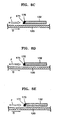
- FIGS. 8A through 8E are partially enlarged sectional views of an actuator taken along line X-X' of FIG. 7 , which show a variety of shapes of the absorption filter 170.
- a surface 171 of the absorption filter 170 confronting the airflow in the direction F is perpendicular to the surface of the disk 120.
- the surface 171 of the absorption filter 170 makes a right angle to the direction F of the airflow generated by the rotation of the disk 120, a possibility that the foreign materials included in the airflow inside the disk drive collide the surface 171 of the absorption filter 170 increases.
- the shape of the absorption filter 170 can be simply and easily manufactured.
- the surface 171 of the absorption filter 170 confronting the airflow in the direction F can be formed inclined to the surface of the disk 120.
- the side surface of the swing arm 132 to which the absorption filter 170 is attached is perpendicular to the surface of the disk 120 while only the surface 171 of the absorption filter 170 is inclined.
- the side surface of the swing arm 132 is inclined to the surface of the disk 120 while the absorption filter 170 has a uniform thickness. In this case, when the absorption filter 170 having a uniform thickness is attached to the inclined side surface of the swing arm 132, the surface 171 of the absorption filter 170 is inclined to the surface of the disk 120.
- the surface 171 of the absorption filter 170 confronting the airflow in the direction F can be formed inclined and curved to the surface of the disk 120.
- the side surface of the swing arm 132 to which the absorption filter 170 is attached is perpendicular to the surface of the disk 120 while only the surface 171 of the absorption filter 170 is inclined and curved.
- the side surface of the swing arm 132 is inclined and curved to the surface of the disk 120 while the absorption filter 170 has a uniform thickness.
- the absorption filter 170 having a uniform thickness is attached to the inclined-in-a-curve side surface of the swing arm 132, the surface 171 of the absorption filter 170 is inclined and curved to the surface of the disk 120.
- the absorption filter 170 having the shapes shown in FIGS. 8B through 8E since the air flows smoothly around the absorption filter 170, the generation of vibration of the disk 120 due to a vortex is reduced or restricted. While the absorption filter 170 is shown as being thinner as a function of distance, it is understood that the absorption filter 170 can have an increasing thickness as a function of distance from the disk 120.
- FIG. 9 is a perspective view illustrating an actuator having an absorption filter 270 according to an aspect of the invention.
- FIG. 10 is a partially magnified sectional view of the actuator taken along line Y-Y' of FIG. 9 .
- the actuator 230 includes a swing arm 232 rotatably coupled with a pivot bearing 231, a slider 234 on which a read/write head is mounted, a suspension 233 coupled to a leading end portion of the swing arm 232 and supporting the slider 234, and the absorption filter 270 to absorb foreign materials in the flowing air.
- An end-tab 235 is provided at the leading end portion of the suspension 233.
- a plurality of the swing arms 232 can be provided according to the number of the disk 220.
- Each of the swing arms 232 has a thin plate shape.
- the swing arms 232 are deposited with a spacer 239 interposed therebetween.
- the swing arm 232 may be formed of a stainless steel plate having a thin thickness of about 0.2 mm so that the height of the side surface thereof is low.
- the swing arm 232 may be formed of other materials having thin thickness and low height.
- the interval between the swing arm 232 and the disk 120 of the second aspect of the invention is larger than that in the first aspect of the invention.
- the height of the side surface of the swing arm 232 (that is, the height of the side surface confronting the airflow in the direction F according to the rotation of the disk 120) is low, attaching the absorption filter 270 to the side surface of the swing arm 232 may not provide a sufficient attachment strength.
- two support portions 272 protrude from a rear surface of the absorption filter 270 and attach to an upper surface and a lower surface of the swing arm 232 to support the absorption filter 270.
- an attachment area between the support portions 272 and the swing arm 232 is as large as possible so as to have a sufficient attachment strength to support the absorption filter 270.
- a single support portion may be formed so as to be attached to one of the upper and lower surfaces of the swing arm 232.
- the absorption filter 270 may be firmly supported by the support-portions 272 attached to the swing arm 232 in a wider area. Also, similar to the aspect of the invention shown in FIGS. 6 through 8E , since the shape or configuration of the swing arm 232 does not need to be changed to attach the absorption filter 270, the absorption filter 270 can be simply applied with the existing actuator 230. Since the interval between the swing arm 232 and the disk 120 increases, the height of the absorption filter 270 can be greater than that of the side surface of the swing arm 232. Thus, since a surface 271 of the absorption filter 270 confronting the airflow in the direction F has a sufficient height, a foreign material collecting area increases.
- the absorption filter 270 may be attached to one side of the swing arm 232 in order to confront the airflow according to the rotation of the disk 120. Thus, collecting foreign materials by the absorption filter 270 is more efficient.
- the surface 271 of the absorption filter 270 can be formed approximately perpendicular to the surface of the disk 120.
- the surface 271 of the absorption filter 270 may be formed inclined to the surface of the disk 120, inclined or curved thereto, as shown in FIGS. 8B and 8E .
- the absorption filter 270 easily absorbs relatively large particles having a size of several hundred nanometers, as in the first aspect of the invention.
- the absorption filter 270 reduces vibrations of the actuator 230 by a damping action thereof.
- the absorption filter is arranged at the side surface of the swing arm to-confront the airflow in a predetermined direction, not only is collecting foreign materials inside the disk drive by the absorption filter more efficient, but relatively large particles having a size of several hundred nanometers can also be collected. Thus, the disk surface and head can be prevented from being damaged by the foreign materials, thereby improving the performance and reliability of the disk drive.
- the vibration of the actuator can be reduced by the damping action of the absorption filter attached to the swing.
- the invention can be easily applied to an actuator in which a plurality of swing arms each having a thin plate shape are deposited.
Landscapes
- Supporting Of Heads In Record-Carrier Devices (AREA)
- Moving Of Heads (AREA)
Claims (16)
- Zugriffsarm eines Plattenlaufwerks, der umfasst:einen Schwenkarm (132, 232), der im Inneren des Plattenlaufwerks installiert ist; undeinen Lese-Schreib-Kopf, der an einem Ende des Schwenkarms (132, 232) angebracht ist, dadurch gekennzeichnet, dass der Zugriffsarm des Weiteren einen Absorptionsfilter (170, 270) zum Absorbieren von Fremdkörpern im Inneren des Plattenlaufwerks umfasst, wobei der Absorptionsfilter (170, 270) an einer Seitenfläche des Schwenkarms (132, 232) so angebracht ist, dass er einem Luftstrom in einer vorgegebenen Richtung entsprechend der Drehung der Platte (120) zugewandt ist, um die Fremdkörper zu absorbieren.
- Zugriffsarm nach Anspruch 1, wobei der Absorptionsfilter (170, 270) den Luftstrom bremst, der die Fremdkörper enthält, und annähernd senkrecht zu einer Aufzeichnungs-Wiedergabe-Fläche der Platte (120) angeordnet ist.
- Zugriffsarm nach Anspruch 1, wobei der Absorptionsfilter (170, 270) eine Fläche hat, die dem Luftstrom in der vorgegebenen Richtung zugewandt ist und sich in einem Winkel von weniger als ungefähr 90° relativ zu der Lese-Wiedergabe-Fläche der Platte (120) befindet.
- Zugriffsarm nach Anspruch 1, wobei der Absorptionsfilter (170, 270) eine Fläche hat, die dem Luftstrom in der vorgegebenen Richtung zugewandt ist und relativ zu der Oberfläche der Platte (120) gekrümmt ist.
- Zugriffsarm nach einem der Ansprüche 1 bis 4, wobei der Absorptionsfilter (170, 270) an dem Schwenkarm (132, 232) unter Verwendung eines Trageabschnitts (272) angebracht ist, der sich von einer hinteren Fläche des Absorptionsfilters (170, 270) aus erstreckt und an die seitliche Fläche des Schwenkarms (132, 232) angrenzend an einer oberen oder einer unteren Fläche angebracht ist, um den Absorptionsfilter (170, 270) zu tragen.
- Zugriffsarm nach Anspruch 5, wobei sich ein Abschnitt des Absorptionsfilters (170, 270) oberhalb der oberen oder der unteren Fläche erstreckt und damit verbunden ist.
- Zugriffsarm nach Anspruch 6, wobei der Absorptionsfilter (170, 270) eine dämpfende Struktur aufweist, um Vibration des Zugriffsarms (130, 230) in dem Plattenlaufwerk abzuschwächen.
- Zugriffsarm nach einem der Ansprüche 1 bis 7, wobei eine Oberfläche des Absorptionsfilters (170, 270) so geformt ist, dass Luft ungehindert um den Absorptionsfilter (170, 270) herum strömt, um eine Erzeugung von Vibration der Platte aufgrund von Verwirbelung zu reduzieren.
- Zugriffsarm nach Anspruch 8, wobei der Absorptionsfilter (170, 270) eine gleichmäßige Dicke hat.
- Zugriffsarm nach Anspruch 1, der des Weiteren eine Aufhängung (133, 233) umfasst, die mit einem vorderen Endabschnitt des Schwenkarms (132, 232) gekoppelt ist und ein Flugelement (slider) (134) trägt, an dem der Lese-Schreib-Kopf angebracht ist.
- Zugriffsarm nach Anspruch 10, wobei der Absorptionsfilter (170, 270) des Weiteren einen Trageabschnitt umfasst, der wenigstens an einer oberen oder einer unteren Fläche des Schwenkarms (132, 232) angebracht ist und den Absorptionsfilter (170, 270) trägt und von einer hinteren Fläche des Absorptionsfilters vorsteht.
- Zugriffsarm nach Anspruch 11, wobei eine Höhe des Absorptionsfilters (170, 270) größer ist als eine Höhe der seitlichen Fläche des Schwenkarms (132, 232).
- Zugriffsarm nach Anspruch 1, wobei eine Fläche des Absorptionsfilters (170, 270), die dem Luftstrom in der vorgegebenen Richtung zugewandt ist, senkrecht zu einer Oberfläche der Platte ist.
- Zugriffsarm nach Anspruch 1, wobei eine Fläche des Absorptionsfilters (170, 270), die dem Luftstrom in der vorgegebenen Richtung zugewandt ist, in Bezug auf eine Oberfläche der Platte (120) geneigt ist.
- Zugriffsarm nach Anspruch 14, wobei die geneigte Fläche des Absorptionsfilters (170, 270) stromlinienförmig und gekrümmt ist.
- Plattenlaufwerk, das umfasst:einen Spindelmotor (112);wenigstens eine Platte (120), die an dem Spindelmotor (112) installiert ist; undeinen Linearmotor, der einen Zugriffsarm (130, 230) nach einem der Ansprüche 1 bis 15 dreht.
Applications Claiming Priority (2)
| Application Number | Priority Date | Filing Date | Title |
|---|---|---|---|
| KR10-2003-0054784A KR100524981B1 (ko) | 2003-08-07 | 2003-08-07 | 흡착 필터를 가진 액츄에이터와 이를 구비한 디스크드라이브 |
| KR2003054784 | 2003-08-07 |
Publications (3)
| Publication Number | Publication Date |
|---|---|
| EP1505604A2 EP1505604A2 (de) | 2005-02-09 |
| EP1505604A3 EP1505604A3 (de) | 2007-08-22 |
| EP1505604B1 true EP1505604B1 (de) | 2010-09-29 |
Family
ID=33550333
Family Applications (1)
| Application Number | Title | Priority Date | Filing Date |
|---|---|---|---|
| EP04016588A Expired - Lifetime EP1505604B1 (de) | 2003-08-07 | 2004-07-14 | Positionieranordnung mit Aufsaugungsfilter und Plattenantrieb mit einer solchen Anordnung |
Country Status (5)
| Country | Link |
|---|---|
| US (1) | US7336439B2 (de) |
| EP (1) | EP1505604B1 (de) |
| JP (1) | JP2005056559A (de) |
| KR (1) | KR100524981B1 (de) |
| DE (1) | DE602004029310D1 (de) |
Families Citing this family (6)
| Publication number | Priority date | Publication date | Assignee | Title |
|---|---|---|---|---|
| US7075753B2 (en) * | 2003-12-16 | 2006-07-11 | Seagate Technology Llc | Clean suspension assembly |
| CN100501836C (zh) * | 2005-06-20 | 2009-06-17 | 新科实业有限公司 | 具有粒子过滤装置的磁头折片组合和磁盘驱动单元 |
| US20090073607A1 (en) * | 2007-09-19 | 2009-03-19 | Seagate Technology Llc | Reduction in Particle Rebound Off of Component Surfaces |
| US8159778B2 (en) | 2009-04-06 | 2012-04-17 | Hitachi Global Storage Technologies, Netherlands B.V. | Hard disk drive contamination control |
| US8427776B2 (en) * | 2010-12-29 | 2013-04-23 | HGST Netherlands B.V. | Reducing air flow exposure to conductive components of a hard disk drive |
| JP2022167569A (ja) * | 2021-04-23 | 2022-11-04 | 株式会社東芝 | 磁気ディスク装置 |
Family Cites Families (6)
| Publication number | Priority date | Publication date | Assignee | Title |
|---|---|---|---|---|
| DE3778427D1 (de) * | 1986-06-04 | 1992-05-27 | Fujitsu Ltd | Magnetplattenvorrichtung. |
| JPH09115280A (ja) | 1995-10-16 | 1997-05-02 | Hitachi Ltd | 磁気ディスク装置 |
| US6362937B1 (en) * | 1999-04-21 | 2002-03-26 | Seagate Technology Llc | Air vane windage accelerator apparatus for a disc drive |
| US6208484B1 (en) * | 1999-06-11 | 2001-03-27 | Maxtor Corporation | Recirculation filter for use in a disk drive |
| JP2001076478A (ja) | 1999-09-03 | 2001-03-23 | Hitachi Ltd | 磁気ディスク装置 |
| KR100510540B1 (ko) * | 2003-08-07 | 2005-08-26 | 삼성전자주식회사 | 순환 필터를 가진 액츄에이터와 이를 구비한 디스크드라이브 |
-
2003
- 2003-08-07 KR KR10-2003-0054784A patent/KR100524981B1/ko not_active Expired - Fee Related
-
2004
- 2004-06-17 US US10/868,958 patent/US7336439B2/en not_active Expired - Fee Related
- 2004-07-14 EP EP04016588A patent/EP1505604B1/de not_active Expired - Lifetime
- 2004-07-14 DE DE602004029310T patent/DE602004029310D1/de not_active Expired - Lifetime
- 2004-08-05 JP JP2004229294A patent/JP2005056559A/ja active Pending
Also Published As
| Publication number | Publication date |
|---|---|
| JP2005056559A (ja) | 2005-03-03 |
| EP1505604A2 (de) | 2005-02-09 |
| KR20050017711A (ko) | 2005-02-23 |
| US20050030664A1 (en) | 2005-02-10 |
| KR100524981B1 (ko) | 2005-10-31 |
| US7336439B2 (en) | 2008-02-26 |
| DE602004029310D1 (de) | 2010-11-11 |
| EP1505604A3 (de) | 2007-08-22 |
Similar Documents
| Publication | Publication Date | Title |
|---|---|---|
| KR100564612B1 (ko) | 하드 디스크 드라이브 | |
| EP0765517B1 (de) | Aerodynamische drehbetätigerverriegelung mit filter für festplattenantrieb | |
| US8432641B1 (en) | Disk drive with multi-zone arm damper | |
| JP5165252B2 (ja) | ハードディスクドライブ | |
| US7307812B2 (en) | Filtering apparatus for disk drive | |
| EP1505604B1 (de) | Positionieranordnung mit Aufsaugungsfilter und Plattenantrieb mit einer solchen Anordnung | |
| US7206165B2 (en) | Noise reducing apparatus for disk drive | |
| KR100518578B1 (ko) | 정보 저장 장치용 파티클 제거장치 및 이를 구비한 램프 | |
| US7573672B2 (en) | Cover member with air guiding portion and hard disk drive including the cover member | |
| KR100510540B1 (ko) | 순환 필터를 가진 액츄에이터와 이를 구비한 디스크드라이브 | |
| CN1941155B (zh) | 具有空气引导部的覆盖构件及硬盘驱动器 | |
| KR100555516B1 (ko) | 디스크 드라이브의 필터링 장치 | |
| KR100919246B1 (ko) | 데이터 저장매체 및 이를 구비한 하드디스크 드라이브 | |
| KR20070103878A (ko) | 램프 및 이를 구비한 하드디스크 드라이브 | |
| JP2007335072A (ja) | ディスクダンパー、ハードディスクドライブ及びディスクダンパーの製造方法 | |
| JPH1166725A (ja) | 磁気ディスク装置 | |
| KR20070034253A (ko) | 데이터 저장매체 및 이를 구비한 하드디스크 드라이브 | |
| KR20060081298A (ko) | 하드디스크 드라이브의 액츄에이터, 및 이의 제조방법 |
Legal Events
| Date | Code | Title | Description |
|---|---|---|---|
| PUAI | Public reference made under article 153(3) epc to a published international application that has entered the european phase |
Free format text: ORIGINAL CODE: 0009012 |
|
| 17P | Request for examination filed |
Effective date: 20040714 |
|
| AK | Designated contracting states |
Kind code of ref document: A2 Designated state(s): AT BE BG CH CY CZ DE DK EE ES FI FR GB GR HU IE IT LI LU MC NL PL PT RO SE SI SK TR |
|
| AX | Request for extension of the european patent |
Extension state: AL HR LT LV MK |
|
| PUAL | Search report despatched |
Free format text: ORIGINAL CODE: 0009013 |
|
| AK | Designated contracting states |
Kind code of ref document: A3 Designated state(s): AT BE BG CH CY CZ DE DK EE ES FI FR GB GR HU IE IT LI LU MC NL PL PT RO SE SI SK TR |
|
| AX | Request for extension of the european patent |
Extension state: AL HR LT LV MK |
|
| AKX | Designation fees paid |
Designated state(s): DE |
|
| 17Q | First examination report despatched |
Effective date: 20080909 |
|
| GRAP | Despatch of communication of intention to grant a patent |
Free format text: ORIGINAL CODE: EPIDOSNIGR1 |
|
| GRAS | Grant fee paid |
Free format text: ORIGINAL CODE: EPIDOSNIGR3 |
|
| GRAA | (expected) grant |
Free format text: ORIGINAL CODE: 0009210 |
|
| AK | Designated contracting states |
Kind code of ref document: B1 Designated state(s): DE |
|
| REF | Corresponds to: |
Ref document number: 602004029310 Country of ref document: DE Date of ref document: 20101111 Kind code of ref document: P |
|
| PLBE | No opposition filed within time limit |
Free format text: ORIGINAL CODE: 0009261 |
|
| STAA | Information on the status of an ep patent application or granted ep patent |
Free format text: STATUS: NO OPPOSITION FILED WITHIN TIME LIMIT |
|
| 26N | No opposition filed |
Effective date: 20110630 |
|
| REG | Reference to a national code |
Ref country code: DE Ref legal event code: R097 Ref document number: 602004029310 Country of ref document: DE Effective date: 20110630 |
|
| PGFP | Annual fee paid to national office [announced via postgrant information from national office to epo] |
Ref country code: DE Payment date: 20130729 Year of fee payment: 10 |
|
| REG | Reference to a national code |
Ref country code: DE Ref legal event code: R119 Ref document number: 602004029310 Country of ref document: DE |
|
| PG25 | Lapsed in a contracting state [announced via postgrant information from national office to epo] |
Ref country code: DE Free format text: LAPSE BECAUSE OF NON-PAYMENT OF DUE FEES Effective date: 20150203 |
|
| REG | Reference to a national code |
Ref country code: DE Ref legal event code: R119 Ref document number: 602004029310 Country of ref document: DE Effective date: 20150203 |