EP1505556A1 - Verfahren und Vorrichtung zur Erkennung eines Flughindernisses - Google Patents
Verfahren und Vorrichtung zur Erkennung eines Flughindernisses Download PDFInfo
- Publication number
- EP1505556A1 EP1505556A1 EP04018510A EP04018510A EP1505556A1 EP 1505556 A1 EP1505556 A1 EP 1505556A1 EP 04018510 A EP04018510 A EP 04018510A EP 04018510 A EP04018510 A EP 04018510A EP 1505556 A1 EP1505556 A1 EP 1505556A1
- Authority
- EP
- European Patent Office
- Prior art keywords
- obstacle
- aircraft
- ground station
- flight
- identifier
- Prior art date
- Legal status (The legal status is an assumption and is not a legal conclusion. Google has not performed a legal analysis and makes no representation as to the accuracy of the status listed.)
- Granted
Links
Images

Classifications
-
- G—PHYSICS
- G08—SIGNALLING
- G08G—TRAFFIC CONTROL SYSTEMS
- G08G5/00—Traffic control systems for aircraft
- G08G5/20—Arrangements for acquiring, generating, sharing or displaying traffic information
- G08G5/26—Transmission of traffic-related information between aircraft and ground stations
-
- G—PHYSICS
- G08—SIGNALLING
- G08G—TRAFFIC CONTROL SYSTEMS
- G08G5/00—Traffic control systems for aircraft
- G08G5/50—Navigation or guidance aids
- G08G5/55—Navigation or guidance aids for a single aircraft
-
- G—PHYSICS
- G08—SIGNALLING
- G08G—TRAFFIC CONTROL SYSTEMS
- G08G5/00—Traffic control systems for aircraft
- G08G5/50—Navigation or guidance aids
- G08G5/57—Navigation or guidance aids for unmanned aircraft
-
- G—PHYSICS
- G08—SIGNALLING
- G08G—TRAFFIC CONTROL SYSTEMS
- G08G5/00—Traffic control systems for aircraft
- G08G5/70—Arrangements for monitoring traffic-related situations or conditions
- G08G5/72—Arrangements for monitoring traffic-related situations or conditions for monitoring traffic
- G08G5/723—Arrangements for monitoring traffic-related situations or conditions for monitoring traffic from the aircraft
-
- G—PHYSICS
- G08—SIGNALLING
- G08G—TRAFFIC CONTROL SYSTEMS
- G08G5/00—Traffic control systems for aircraft
- G08G5/80—Anti-collision systems
Definitions
- the invention is based on a method for detecting a flying obstacle in an environment of an aircraft, in particular an unmanned aerial vehicle, at least two images each of at least a portion of the environment be recorded from the images the obstacle detected and with a Identification is provided and one of the identifier associated signal in a ground station is issued.
- the invention is also based on a device for detecting a Flight obstacle in an environment of an aircraft, in particular an unmanned aerial vehicle Aircraft, with at least one camera unit for recording at least a part of the environment and an evaluation device for detecting the Flight obstacle and an assignment of an identifier to the obstacle.
- a method for displaying a flying object in which an environment of an unmanned aerial vehicle with a number is captured by cameras and the images are sent to a ground station and be displayed on a display for a ground pilot.
- the ground pilot can control the aircraft based on the images shown, looking for flying objects near the aircraft by aids, such as flashing Symbols in the picture shown, is pointed.
- the constant active observation from electronically generated images in which only occasionally a flying object is recognizable, but is very tiring for a ground pilot, which he his responsibility for the safety of the aircraft with regard to a collision warning only with considerable concentration over a long period of time bill can carry.
- the invention is therefore based on the object, in particular with respect to the Handleability improved method for representing a flying obstacle specify.
- the invention is also based on the object, a device indicate that such a procedure can be initiated in a simple manner can.
- the former object is achieved by a method of the type mentioned solved, according to the invention to the detection and the assignment of the identifier Board of the aircraft are made and the identifier to the ground station is sent.
- ground pilot Information By sending the ID and possibly further detailed information to the ground station will be provided to the ground pilot Information reduced to a necessary and reasonable minimum.
- the ground pilot is therefore no longer the task, an airspace around the aircraft to actively observe images. This can increase the efficiency of Work of the ground pilot increased and thus increased safety.
- the renunciation of the transmission of moving images from the entire environment the aircraft is also transmitted by the aircraft to the ground station Data volume kept low. The remote data transmission can thus with low capacity and cost-effective.
- Airborne obstacles can be flying objects such as airplanes, helicopters, balloons or similar and ground-based objects such as towers, buildings, bridges, Masts, cables, etc. are detected. It is sufficient if the flight obstacles be recognized as such.
- the flight obstacles should be recognized, if they are in the vicinity of the aircraft, thus at a distance to maximum 3 km, advantageously up to 5 km and in particular up to 8 km, for example depending on visibility conditions and / or size and visibility of the flying obstacle.
- images of the surroundings of the aircraft are taken, are expected to be prioritized within the flight obstacles, for example in one Solid angle range of at least 110 ° in the horizontal direction on both sides Longitudinal axis of the aircraft and at least 30 ° in the vertical direction on both sides the longitudinal axis.
- the images are preferably from a passive wide-angle sensor recorded with a high resolution.
- the sensors are designed that there are sufficient environmental obstacles in the area and at a sufficient distance and with the lowest possible false alarm rate can be detected to allow sufficient time for an evasive maneuver to make available.
- the resolution of these pictures is expediently at least 2 mrad, in particular at least 0.3 mrad, which is the maximum corresponds to the foveal resolution of the human eye.
- the images, from which an evaluation device detects the obstacle can created by a continuous recording of image information be. It is also possible to take pictures in any or given temporal Record timing.
- the frame rate, the field of view and the resolution be designed so that either with one or a few rigidly mounted cameras high pixel count or with one or more cameras with smaller but sufficient Pixel count and an additional scanner system the desired environment is covered.
- two or more can be consecutive taken pictures with the help of an image processing unit aboard the Processed aircraft, for example, compared to each other.
- An image processing in itself which allows such recognition of an object from images, is known for example from Görz, Rollinger, Schneeberger: “Handbuch der Artificial Intelligence ", Oldenbourg Verlag, 2000, chapter 21.4 Detecting two or more images in a different spectral range recorded, for example in the visual and infrared Area, compared with each other.
- the Obstacle assigned an identifier.
- Such an identifier can be a signal for example, be a string.
- the ID is then sent to a Transmitter passed, which sends the identifier to the ground station.
- the transmitting device transmits the identifier directly sends to that ground station in which a signal associated with the identifier is issued.
- the identifier can indirectly via another ground station, a satellite, or via an aircraft serving as a relay station for issuing Ground station to be transmitted.
- the assigned signal is output, that the ground pilot can perceive it, for example as a visual one Object on a display means such as a screen or projection device, or as an acoustic signal or both together.
- the procedure is special suitable for use as a collision warning method.
- a classification of a Danger potential of the flying obstacle on board the aircraft made.
- Such a classification may be a control device on board the aircraft serve as a basis for decision whether an intervention in the currently flown Course carried out without a corresponding command of a ground pilot shall be.
- the classification of the risk potential sent to the ground station A ground pilot can quickly identify in this way whether a rapid intervention is necessary due to a dangerous situation.
- the danger potential can be determined from the visual line rotation speed, the apparent size of the obstacle, its rate of change in the recorded images, the elevation angle or elevation angle, the relative Height to the aircraft or a remaining response time up to a calculated Collision result.
- an unsafe detection can be one or more Categories in the classification form, so that uncertain recognized Obstacles are only reported to the ground station if they are a significant Pose danger potential for the aircraft. This can cause false alarms be kept low.
- the classification can be in the classes "high”, “medium” and “low”, in a finer or continuous division or, still more differentiated, according to different types of dangers.
- Important information about a detected obstacle can be obtained by making a measurement with respect to the flight obstacle with an active Measurement signal is performed.
- a measurement signal can be emitted by the aircraft be and is for example a laser beam or a radar signal.
- the Measurement signal can be used for a distance measurement or for a measurement of the differential speed between the flight obstacle and the aircraft used become. Such measurements may be used to calculate a remaining reaction time be used up to a possible collision.
- the won Information can be passed on to the ground pilot and / or for classification the danger potential are used. Carrying out the measurement with the active measuring signal can be controlled by the ground pilot or automatically be performed, for example, when exceeding a predetermined Hazard potential.
- any detected flight obstacle basically an active measurement, for example a distance measurement, perform these types of measurements for disregard of For example, can serve to remove flying obstacles for a ground pilots are of little or no interest.
- An active sensor has usually a limited field of view, which is why they expediently independently movable and swiveled to an interesting obstacle is.
- a Ausweichtrajektorie is determined and in particular the evasion trajectory associated Data is transmitted to the ground station.
- the avoidance trajectory on board the aircraft not only eliminates the calculation a corresponding evasion trajectory in the ground station, but it will the basic requirement for a flight of the aircraft with autopilot without one absolutely necessary radio contact to ground station created.
- This can The safety of the aircraft can be substantially increased, as in case of failure of a Radio contact between a ground station and the aircraft's capability of the aircraft is maintained to independently determine an evasion trajectory and fly along this evasion trajectory.
- a control of the aircraft With the help of an autopilot independently around an obstacle around then can make sense be when the reaction time to a calculated collision is no longer sufficient to give the ground pilot the decision-making responsibility for an evasive maneuver to hand over. With a sufficient reaction time of the Ausweichtrajektorie expediently to the ground station transmitted. For a ground pilot, the avoidance trajectory can be used as an alternative are displayed.
- the avoidance trajectory is included with on board determined information about the environment and / or the flight situation of Aircraft detected.
- Information about the environment can be further recognized Obstacles and in particular their potential danger or be the Aircraft surrounding landscape, such as mountains and valleys.
- Information about the environment and in particular about the flight situation of the aircraft are usually in one Ground station to a lesser extent than in the aircraft before. Calculating the Evasion trajectory aboard the aircraft thus allows for inclusion much more complete information than is usually the case in a calculation would be possible in the ground station.
- a ground pilot will fly over on an evasion trajectory decide and initiate such an evasive maneuver.
- a very low Reaction time may be beneficial to the safety of the aircraft Decide if the aircraft should fly on an evasion trajectory a control device is taken on board the aircraft.
- a control device is taken on board the aircraft.
- such automatic from ground pilots manual disengageable so that the aircraft does not have unforeseen evasive maneuvers performs, which are explicitly not wanted by the ground pilot.
- the ground pilot can as a basis for decision, whether an evasive maneuver should be initiated, meaningful additional information offered by a sent the flying obstacle performing detail image to the ground station and there is shown.
- Such a detail picture shows only a detail of the overall picture of the monitored room.
- the ground pilot will also use this detail image for information in the form of a symbol a real image, for example in the infrared or in the visual spectral range, by which it detects the object of the flight outgoing danger potential can better estimate.
- This detail picture, the obstacle and preferably a small section of the environment of Flying obstacle represents, at the request of the ground pilot or automatically be sent with the identifier to the ground station. It is also possible, that the detail image automatically starts from a preset hazard potential of Aircraft is transmitted to the ground station.
- the detail image can be arranged by a movable in the aircraft and on the Airborne detectable detail camera be recorded.
- the detail image expediently optically zoomable, causing the ground pilots the easy recognition of the flying obstacle is facilitated.
- the detail image is a picture detail of a recognition of the obstacle used. It may be on an additional shot the detail image is omitted and the detail image very quickly from existing Data are selected and transmitted to the ground station. It is also possible that the detail image first selected from existing artwork and is sent to the ground station, for example automatically with the identifier, and in addition to a special request of the ground pilot in addition a detail camera directed to the specified obstacle.
- An infrared camera unit can be based on a line scanner or a wide-angle scanning method be conceived.
- the Ground pilots For the estimation of the danger potential important additional information for the Ground pilots can be obtained by taking the detail image in a spectral range which is different from the spectral range for detection of the obstacle used distinguishes images. In the dark or Twilight, for example, used to detect the obstacle Be included in the infrared spectral range, the Detail image taken for easier interpretation in the visible spectral range becomes. Conversely, it is also possible that the detection of the flying problem taken pictures in the visible spectral range and the ground pilot requests a detail image in the infrared spectral range, for example, to assess the risk potential of the flying obstacle.
- the detail image may be a single image that is similar to the flying obstacle Photo shows. Also possible is an image processed by image processing e.g. only contours. Appropriately, a moving image of the flying obstacle sent to the ground station, for example in the manner of a video, whereby the Ground pilots additional information about the movement of the flying obstacle can be delivered.
- the object related to the device is achieved by a device of the initially solved type mentioned, in the present invention, the evaluation device electrically with the camera and a transmitting device for sending the identifier connected to a ground station.
- the evaluation device electrically with the camera and a transmitting device for sending the identifier connected to a ground station.
- the electrical connection of the evaluation device with the camera and the transmitting device eliminates the need the data transmission of complete images and thus large amounts of data from the aircraft to the ground station.
- the aircraft may be in a dangerous situation be guided independently of a radio contact to the ground station.
- the information offered to the ground pilot is essential Minimum limited.
- the electrical connection can, for example via a wire or indirectly via an electrical circuit can be achieved.
- the electrical connection is also a mechanical connection between the evaluation device and the camera and transmitting device possible, for example, by these devices for common arrangement in the aircraft are provided.
- a detail image can be transmitted to a ground pilot quickly and with little effort be when the device is a detail image unit for the extraction of a the flight obstacle imaging detail image and passing on the detail image to Transmitting device has.
- the device expediently comprises a first camera unit for recording an overall image in a first spectral range and a second camera unit for capturing an image, in particular a detail image, in one of first different spectral range.
- the picture can be a full picture or a Detail picture, wherein the second camera unit for recording in the visual or infrared spectral range or for recording reflected laser or Radar beams is provided.
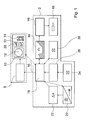
- FIG. 1 shows a block diagram of a device 2 for detecting and for guiding an aircraft 4 (FIG. 2) completely on board the aircraft 4 is arranged.
- the aircraft 4 is an unmanned aerial vehicle 4, for example a reconnaissance plane or transport plane.
- a ground station 6 In a ground station 6 are a device 8 for graphical representation and a device 10 for Communication with a ground pilot to work with the device 2 arranged.
- the device 10 for communication with a ground pilot comprises a display means 12 in the form of a screen, two further screens for displaying detail images 38, another screen 13 for written advertisements of additional information and a number of tax credits 14 for input of control commands.
- the dashed arrows 16 is a radio contact between the ground station. 6 and a control device 18 of the device 2 indicated.
- To communication via remote data transmission with the ground station 6 comprises the control device 18 a transmitting device for the transmission of identifiers and a Receiving device.
- the control device 18 is electrically connected to a unit 20 for emitting and receiving laser light and a unit 22 for distance calculation.
- Also with the control device 18 electrically connected is a camera unit 24 for recording an overall image in the spectral range of visible light.
- an evaluation device 26 is arranged, which is a Image processing unit includes.
- the evaluation device 26 is for detection an obstacle 28, 30, 32, 34 ( Figure 2) and to assign an identifier to the obstacle 28, 30, 32, 34 is provided.
- the device includes 2, a second camera unit 36, which is provided for receiving a detail image 38 is.
- the control device 18 is, inter alia, for the calculation of an evasion trajectory 42 ( Figure 3) and is for this purpose in a data connection with a flight information unit 44.
- the flight information unit 44 comprises Data about the immediate environment of the aircraft 4, such as the Scenic environment and data about the flight situation of the aircraft 4, such as For example, the current airspeed and the orientation of the Aircraft 4 in the room. Also electrically with the control device 18 connected to a flight control unit 46, which is used to control a Flugaktorik 48 with Engines and hydraulic devices is provided.
- a method for visualizing flight obstacles 28, 30, 32, 34 in the environment of the aircraft 4 and for guiding the aircraft 4 is based on the schematic Representation in Figures 2 and 3 explained in more detail below.
- the camera unit 24 for capturing an overall image becomes an environment 50 of the aircraft 4 recorded in one or more images.
- This overall picture is arranged symmetrically about the direction of flight 52 of the aircraft 4 and covers a solid angle range of 220 ° in the horizontal and 60 ° in the Vertical.
- the camera unit 24 comprises four Cameras, each with a sensor array with an image resolution of 1 mrad. After taking a first overall picture of the environment 50 is of the Camera unit 24 a second and possibly other overall images of the environment 50 recorded.
- the overall images become the evaluation device 26 passed and there with the help of image processing methods on flying obstacles 28, 30, 32, 34 in the environment 50 examined.
- flying obstacles 28, 30, 32, 34 are recognized directly and two more objects are considered as possible candidates detected for further flight obstacles 32, 34.
- the evaluation device 26 Based on the following from the Camera unit 24 recorded and processed by the evaluation device 26 Images, the flight obstacles 28, 30, 32, 34 further processed and Information about them stored in the evaluation device 26. In addition, will the flight obstacles 28, 30, 32, 34 each provided with an identifier and This total information is forwarded to the control device 18.
- the control device 18 calculates a danger potential that can be developed from the images the flight obstacles 28, 30, 32, 34 for the aircraft 4 with the help of Line of sight rotation speed and distance of the flying obstacles 28, 30, 32, 34, a shape and size changing from image to image, as well as the relative Height of flight obstacles 28, 30, 32, 34.
- the two flying obstacles 28, 30 are considered to be on a trajectory 54 or 56 moving aircraft detected.
- the obstacle obstacle 28th No danger to the aircraft 4, because the flying obstacle 28 much lower flies as the aircraft 4.
- the danger potential of the flying obstacle 28 is therefore classified as low.
- the obstacle 30 is considered to be on a collision course calculated with the aircraft 4 flying. This can also be an expected Collision point 60 are determined.
- the danger potential of the flying matter 30 is therefore classified as very high. Due to this high classification a calculation of the avoidance trajectory 42 is automatically initiated. The calculation is included by the control device 18 of information about the environment 50 and the flight situation of the aircraft 4, which are stored in the flight information unit 44 performed.
- the ID associated with the flight obstacles 28, 30 is used together with the determined classification of the hazard potential of the flight obstacles 28, 30 of the Ground station 6 transmitted by radio, where these data using the device. 8 prepared for graphical representation and displayed on the display means 12 become.
- a possible representation on the display means 12 is shown in FIG.
- the display means 12 comprises a screen 62 on which an aircraft icon 64 is shown, with which the position of the aircraft 4 are shown should.
- On screen 62 is also the obstacle 28 through an object 66 and the trajectory 54 of the flying obstacle 28.
- an object 68 In another and more conspicuous color and / or shape is an object 68 that represents the position of the flying obstacle 30.
- the objects 66, 68 are common, in TCAS (Traffic Collision Avoiding System) used symbols.
- the Ground pilot with a synthetic voice on all flight obstacles 30, 34 attentive made that exceed a given hazard class. It is also possible, the transmitted from the aircraft 4 identifier only in the form of an acoustic Output signals such as a voice or a tone sequence.
- a ground pilot can directly detect the potential danger of flight obstacles 28, 30 recognize.
- the trajectories 54, 56 serve him and the possible collision point 60.
- further additional information such as the remaining reaction time until reaching the collision point 60 and information about the Flight situation of the aircraft and possibly on the environment of the aircraft 4, displayed.
- the ground pilot can initiate an evasive maneuver, whereby he is free, the fallback proposal to follow along evasion trajectory 42 or another Route to choose. If the remaining reaction time is below the preset one Time value, then the flying of an evasive maneuver is automatically by the Control device 18 initiated. In this case, the control device act 18, the flight information unit 44, the flight control unit 46 and the flight actuator 48 in such a way that the aircraft 4 along the evasion trajectory 42 to be led.
- the two of the evaluation device 26 not identified as aircraft Flight obstacles 32, 34 are examined on the basis of further pictures. This is detected by the evaluation device 26 that the flying obstacle 32 a very small Airspeed on a trajectory 72 has. This trajectory 72 is coming not near the trajectory 58 of the aircraft 4. In addition, it is recognized that the obstacle 32 is far away from the aircraft 4. The obstacle 32 associated hazard potential is therefore used by the control device 18 as classified so low that the ID assigned to the flight obstacle 32 is not the ground station 6 is transmitted. The decision as to the potential danger Flight obstacles displayed on the display means 12 of the ground station 6 can be set by a ground pilot by means of the control means 14 become.
- the also not identifiable as aircraft aircraft obstacle 34 has a very low visual line rotation speed, so that the flying obstacle 34 a hazard potential is assigned, which is set by the ground pilot Display threshold exceeds. Because the object size in the sequence of recorded images does not grow, but the obstacle 34 can not be assigned more or less exact distance, with only detectable is that the flight obstacle is due to the non-growing object size in a relatively large distance. The the obstacle 34 associated Identification is thus transmitted to the ground station 6 and it becomes a possible Stay area 74 of the flying obstacle 34 34 displayed on the screen.
- the ground pilot can use the second camera unit 36 for taking a detail image in the visible spectral range sensitive to the obstacles 28, 30, 34.
- the camera unit 36 is an optically zoomable to a maximum of 10 ° by 10 ° detail image with a resolution of not more than 0.1 mrad recorded, the control device 18 passed, the ground station 6 transmitted and on the device 10 (FIG 1).
- the ground pilot can see on these detail images 38 that it is at the obstacle 30 to a traffic machine and the obstacle 28 is about a helicopter.
- the detail screens 38 are constantly updated, so that the ground pilot in each case a moving image of the flight obstacles 28, 30 is shown.
- the evaluation device 26 comprises a detail image unit for extracting a an obstacle obstacle 28, 30, 34 depicting detail image 38 and for passing the Detail picture 38 to the transmitting device.
- the Ground pilot on a representation of the flying obstacle 34 in a further detail image Dispense on the flying obstacle 34 as a small weather balloon would have been recognized.
- the unit 20 for transmission and be activated to receive laser light and with the help of the unit 22 the Removal of the flying obstacle 34 are determined.
- the determined distance is passed from the unit 22 of the control device 18, which is the Flugindemis If necessary, assign a new hazard potential and this together with the identifier of the flying obstacle 34 sends to the ground station 6.
- the residence area 74 on the screen 62 by another Object replaces the distance of the flying obstacle 34 reproduces.
- the color and shape of the object is the classification of the hazard potential of the flying obstacle 34 adjusted.
- the four cameras of the camera unit 24 for taking a complete picture are in visible spectral range sensitive. As well it is possible that these four Cameras in the infrared spectral range are sensitive, creating a night vision capability could be reached. As described above, the recognition of the Obstacles 28, 30, 32, 34 also in this case using one of the camera unit 24 recorded image sequence made. As another variant it is possible to equip the camera unit 24 with a number of cameras, from some in the infrared spectral range and others in the visual spectral range are sensitive. Detection of the flight obstacles 28, 30, 32, 34 can in this case, based on a sequence of images or comparing images be performed in different spectral ranges.
Landscapes
- Engineering & Computer Science (AREA)
- Aviation & Aerospace Engineering (AREA)
- Physics & Mathematics (AREA)
- General Physics & Mathematics (AREA)
- Traffic Control Systems (AREA)
- Radar Systems Or Details Thereof (AREA)
- Measurement Of Velocity Or Position Using Acoustic Or Ultrasonic Waves (AREA)
Abstract
Description
- Fig. 1
- ein schematisches Blockdiagramm einer Vorrichtung zur Erkennung und zum Führen eines Fluggeräts,
- Fig. 2
- eine schematische Darstellung einer Umgebung eines Fluggeräts und
- Fig. 3
- eine Bildschirmdarstellung der Umgebung aus Fig. 2.
- 2
- Vorrichtung
- 4
- Fluggerät
- 6
- Bodenstation
- 8
- Vorrichtung
- 10
- Vorrichtung
- 12
- Anzeigemittel
- 13
- Bildschirm
- 14
- Steuermittel
- 16
- Pfeil
- 18
- Steuerungsvorrichtung
- 20
- Einheit
- 22
- Einheit
- 24
- Kameraeinheit
- 26
- Auswertevorrichtung
- 28
- Flughindernis
- 30
- Flughindernis
- 32
- Flughindernis
- 34
- Flughindernis
- 36
- Kameraeinheit
- 38
- Detailbild
- 42
- Ausweichtrajektorie
- 44
- Fluginformationseinheit
- 46
- Flugregeleinheit
- 48
- Flugaktorik
- 50
- Umgebung
- 52
- Flugrichtung
- 54
- Flugbahn
- 56
- Flugbahn
- 58
- Flugbahn
- 60
- Kollisionspunkt
- 62
- Bildschirm
- 64
- Fluggerätsymbol
- 66
- Objekt
- 68
- Objekt
- 72
- Flugbahn
- 74
- Aufenthaltsbereich
Claims (14)
- Verfahren zur Erkennung eines Flughindernisses (28, 30, 32, 34) in einer Umgebung (50) eines Fluggeräts (4), insbesondere eines unbemannten Fluggeräts (4), bei dem mindestens zwei Bilder jeweils zumindest eines Teils der Umgebung (50) aufgenommen werden, aus den Bildern das Flughindernis (28, 30, 32, 34) erkannt und mit einer Kennung versehen wird und ein der Kennung zugeordnetes Signal (66, 68, 76) in einer Bodenstation (6) ausgegeben wird,
dadurch gekennzeichnet, dass
die Erkennung und die Vergabe der Kennung an Bord des Fluggeräts (4) vorgenommen werden und die Kennung an die Bodenstation (6) gesendet wird. - Verfahren nach Anspruch 1,
dadurch gekennzeichnet, dass
eine Klassifizierung eines Gefahrenpotentials des Flughindernisses (28, 30, 32, 34) an Bord des Fluggeräts (4) vorgenommen und insbesondere an die Bodenstation (6) gesendet wird. - Verfahren nach Anspruch 1 oder 2,
dadurch gekennzeichnet, dass
eine Messung mit Bezug auf das Flughindernis (28, 30, 32, 34) mit einem aktiven Messsignal durchgeführt wird. - Verfahren nach einem der vorhergehenden Ansprüche,
dadurch gekennzeichnet, dass
an Bord eine Ausweichtrajektorie (42) ermittelt und insbesondere der Ausweichtrajektorie (42) zugeordnete Daten an die Bodenstation (6) übermittelt werden. - Verfahren nach Anspruch 4,
dadurch gekennzeichnet, dass
die Ausweichtrajektorie (42) unter Einbeziehung von an Bord ermittelten Informationen über die Umgebung (50) und/oder die Flugsituation des Fluggeräts (4) ermittelt wird. - Verfahren nach Anspruch 4 oder 5,
dadurch gekennzeichnet, dass
eine Entscheidung, ob das Fluggerät (4) auf der Ausweichtrajektorie (42) fliegen soll, von einer Steuerungsvorrichtung (18) an Bord des Fluggeräts (4) getroffen wird. - Verfahren nach einem der vorhergehenden Ansprüche,
dadurch gekennzeichnet, dass
ein das Flughindernis (28, 30) darstellendes Detailbild (38) zur Bodenstation (6) gesendet und dort angezeigt wird. - Verfahren nach Anspruch 7,
dadurch gekennzeichnet, dass
als Detailbild (38) ein Bildausschnitt eines zur Erkennung des Flughindernisses (28, 30) verwendeten Bilds verwendet wird. - Verfahren nach Anspruch 7 oder 8,
dadurch gekennzeichnet, dass
das Detailbild (38) in einem Spektralbereich aufgenommen wird, der sich von dem Spektralbereich der zur Erkennung des Flughindernisses (28, 30, 32, 34) verwendeten Bilder unterscheidet. - Verfahren nach einem der vorhergehenden Ansprüche,
dadurch gekennzeichnet, dass
die Bilder, aus denen das Flughindernis (28, 30, 32, 34) erkannt wird, im infraroten Spektralbereich aufgenommen werden. - Verfahren nach einem der vorhergehenden Ansprüche,
dadurch gekennzeichnet, dass
ein Bewegtbild des Flughindernisses (28, 30) zur Bodenstation (6) gesendet wird. - Vorrichtung zur Erkennung eines Flughindernisses (28, 30, 32, 34) in einer Umgebung (50) eines Fluggeräts (4), insbesondere eines unbemannten Fluggeräts (4), mit mindestens einer Kameraeinheit (24) zur Aufnahme zumindest eines Teils der Umgebung (50) und einer Auswertevorrichtung (26) zur Erkennung des Flughindernisses (28, 30, 32, 34) und einer Zuordnung einer Kennung zum Flughindernis (28, 30, 32, 34),
dadurch gekennzeichnet, dass
die Auswertevorrichtung (26) elektrisch mit der Kameraeinheit (24) und einer Sendeeinrichtung zur Sendung der Kennung an eine Bodenstation (6) verbunden ist. - Vorrichtung nach Anspruch 12,
gekennzeichnet durch
eine Detailbildeinheit zur Extraktion eines das Flughindernis (28, 30) abbildenden Detailbilds (38) und zur Weitergabe des Detailbilds (38) an die Sendeeinrichtung. - Vorrichtung nach Anspruch 12 oder 13,
gekennzeichnet durch eine erste Kameraeinheit (24) zur Aufnahme eines Gesamtbilds in einem ersten Spektralbereich und eine zweiten Kameraeinheit (36) zur Aufnahme eines Bilds, insbesondere eines Detailbilds (38), in einem vom ersten unterschiedlichen Spektralbereich.
Applications Claiming Priority (2)
| Application Number | Priority Date | Filing Date | Title |
|---|---|---|---|
| DE10336928 | 2003-08-07 | ||
| DE10336928 | 2003-08-07 |
Publications (2)
| Publication Number | Publication Date |
|---|---|
| EP1505556A1 true EP1505556A1 (de) | 2005-02-09 |
| EP1505556B1 EP1505556B1 (de) | 2005-10-05 |
Family
ID=33547187
Family Applications (1)
| Application Number | Title | Priority Date | Filing Date |
|---|---|---|---|
| EP04018510A Expired - Lifetime EP1505556B1 (de) | 2003-08-07 | 2004-08-05 | Verfahren und Vorrichtung zur Erkennung eines Flughindernisses |
Country Status (4)
| Country | Link |
|---|---|
| US (1) | US7061401B2 (de) |
| EP (1) | EP1505556B1 (de) |
| AT (1) | ATE306112T1 (de) |
| DE (1) | DE502004000085D1 (de) |
Cited By (4)
| Publication number | Priority date | Publication date | Assignee | Title |
|---|---|---|---|---|
| WO2008020889A3 (en) * | 2006-03-13 | 2008-04-03 | Boeing Co | Aircraft collision sense and avoidance system and method |
| DE102011016964A1 (de) | 2011-04-13 | 2012-10-18 | Diehl Bgt Defence Gmbh & Co. Kg | Verfahren zum Überwachen eines Luftraums um ein Luftfahrzeug |
| EP2485107A3 (de) * | 2011-02-08 | 2013-03-13 | EADS Deutschland GmbH | Unbemanntes Luftfahrzeug mit eingebautem Kollisionswarnsystem |
| CN105868835A (zh) * | 2016-04-01 | 2016-08-17 | 北京飞蝠科技有限公司 | 一种无人机在线预约服务平台的评价系统及方法 |
Families Citing this family (55)
| Publication number | Priority date | Publication date | Assignee | Title |
|---|---|---|---|---|
| JP4376653B2 (ja) * | 2004-02-17 | 2009-12-02 | 富士重工業株式会社 | 車外監視装置 |
| US7228232B2 (en) * | 2005-01-24 | 2007-06-05 | International Business Machines Corporation | Navigating a UAV with obstacle avoidance algorithms |
| US20060235584A1 (en) * | 2005-04-14 | 2006-10-19 | Honeywell International Inc. | Decentralized maneuver control in heterogeneous autonomous vehicle networks |
| DE102005047273B4 (de) * | 2005-10-01 | 2008-01-03 | Eads Deutschland Gmbh | Verfahren zur Unterstützung von Tiefflügen |
| US8855846B2 (en) * | 2005-10-20 | 2014-10-07 | Jason W. Grzywna | System and method for onboard vision processing |
| US20100121575A1 (en) * | 2006-04-04 | 2010-05-13 | Arinc Inc. | Systems and methods for aerial system collision avoidance |
| FR2913800B1 (fr) * | 2007-03-13 | 2010-08-20 | Thales Sa | Dispositifs et procedes de filtrage d'alertes anti-collision de terrain et d'obstacles pour aeronef |
| EP2153245A1 (de) * | 2007-05-04 | 2010-02-17 | Teledyne Australia Pty Ltd. | Kollisionsvermeidungssystem und verfahren |
| DE102007032084A1 (de) * | 2007-07-09 | 2009-01-22 | Eads Deutschland Gmbh | Kollisions- und Konfliktvermeidungssystem für autonome unbemannte Flugzeuge (UAV) |
| US8868787B2 (en) * | 2007-12-26 | 2014-10-21 | Honeywell International Inc. | Incremental downlink of flight information |
| DE102008024308B4 (de) * | 2008-05-20 | 2010-12-09 | Eads Deutschland Gmbh | Verfahren zur Detektion nichtkooperativen Luftverkehrs an Bord eines Luftfahrzeugs |
| FR2933523B1 (fr) * | 2008-07-01 | 2014-04-18 | Airbus France | Procede et dispositif d'aide a la conduite d'un vehicule,en particulier d'un aeronef, pour l'evitement d'obstacles |
| EP2159779B1 (de) * | 2008-08-27 | 2013-01-16 | Saab Ab | Verwendung von Bildsensor und Nachlauffilter für verbleibende Zeit, um Kollisionen in der Luft zu vermeiden |
| US8543265B2 (en) * | 2008-10-20 | 2013-09-24 | Honeywell International Inc. | Systems and methods for unmanned aerial vehicle navigation |
| US8626361B2 (en) * | 2008-11-25 | 2014-01-07 | Honeywell International Inc. | System and methods for unmanned aerial vehicle navigation |
| US8570211B1 (en) * | 2009-01-22 | 2013-10-29 | Gregory Hubert Piesinger | Aircraft bird strike avoidance method and apparatus |
| US8380367B2 (en) * | 2009-03-26 | 2013-02-19 | The University Of North Dakota | Adaptive surveillance and guidance system for vehicle collision avoidance and interception |
| US8494760B2 (en) * | 2009-12-14 | 2013-07-23 | American Aerospace Advisors, Inc. | Airborne widefield airspace imaging and monitoring |
| US9355565B2 (en) * | 2010-06-23 | 2016-05-31 | Honeywell International Inc. | Crossing traffic depiction in an ITP display |
| US8626428B2 (en) * | 2011-06-28 | 2014-01-07 | Honeywell International Inc. | Selectable display of aircraft traffic on tracks |
| DE102011121616A1 (de) * | 2011-12-20 | 2013-06-20 | Audi Ag | Verfahren zur Ansteuerung einerAnzeigeeinrichtung eines Kraftfahrzeugs |
| EP2808455B1 (de) * | 2012-01-27 | 2018-05-30 | Doosan Infracore Co., Ltd. | Vorrichtung zur erhöhung der betriebsstabilität einer baumaschine |
| US9002719B2 (en) | 2012-10-08 | 2015-04-07 | State Farm Mutual Automobile Insurance Company | Device and method for building claim assessment |
| CA2833985C (en) * | 2012-11-19 | 2020-07-07 | Rosemount Aerospace, Inc. | Collision avoidance system for aircraft ground operations |
| US10502584B1 (en) | 2012-12-28 | 2019-12-10 | Sean Patrick Suiter | Mission monitor and controller for autonomous unmanned vehicles |
| US20140343765A1 (en) | 2012-12-28 | 2014-11-20 | Sean Patrick Suiter | Flight Assistant with Automatic Configuration and Landing Site Selection |
| US11657721B1 (en) | 2013-08-26 | 2023-05-23 | Otto Aero Company | Aircraft with flight assistant |
| US12260769B1 (en) | 2012-12-28 | 2025-03-25 | Otto Aero Company | System and apparatus for reducing the urgency of a flight condition |
| US9821910B1 (en) * | 2015-05-19 | 2017-11-21 | uAvionix Corporation | Unmanned vehicle control system and apparatus |
| US8872818B2 (en) | 2013-03-15 | 2014-10-28 | State Farm Mutual Automobile Insurance Company | Methods and systems for capturing the condition of a physical structure |
| US8818572B1 (en) | 2013-03-15 | 2014-08-26 | State Farm Mutual Automobile Insurance Company | System and method for controlling a remote aerial device for up-close inspection |
| US9082015B2 (en) | 2013-03-15 | 2015-07-14 | State Farm Mutual Automobile Insurance Company | Automatic building assessment |
| US9674490B2 (en) * | 2013-04-18 | 2017-06-06 | Magna Electronics Inc. | Vision system for vehicle with adjustable cameras |
| JP6329642B2 (ja) | 2013-12-10 | 2018-05-23 | エスゼット ディージェイアイ テクノロジー カンパニー リミテッドSz Dji Technology Co.,Ltd | センサ融合 |
| US9562773B2 (en) | 2014-03-15 | 2017-02-07 | Aurora Flight Sciences Corporation | Autonomous vehicle navigation system and method |
| US9875661B2 (en) | 2014-05-10 | 2018-01-23 | Aurora Flight Sciences Corporation | Dynamic collision-avoidance system and method |
| CN114675671B (zh) | 2014-09-05 | 2025-10-21 | 深圳市大疆创新科技有限公司 | 多传感器环境地图构建 |
| JP6181300B2 (ja) | 2014-09-05 | 2017-08-16 | エスゼット ディージェイアイ テクノロジー カンパニー リミテッドSz Dji Technology Co.,Ltd | 無人航空機の速度を制御するシステム |
| EP3399381A1 (de) | 2014-09-05 | 2018-11-07 | SZ DJI Technology Co., Ltd. | Kontextbasierte flugmodusauswahl |
| US9583011B2 (en) * | 2015-01-28 | 2017-02-28 | Airbus Helicopters | Aircraft system for signaling the presence of an obstacle, an aircraft equipped with this system, and method for the detection of an obstacle |
| US9607447B2 (en) * | 2015-03-31 | 2017-03-28 | Honeywell International Inc. | Automated transmission of aircraft anomalous incident data via preferred transmission modes |
| RU2661269C2 (ru) * | 2015-08-04 | 2018-07-13 | Акционерное общество "Концерн радиостроения "Вега" | Способ траекторного управления беспилотным летательным аппаратом для облета городской застройки в вертикальной плоскости |
| US9787951B2 (en) * | 2015-12-18 | 2017-10-10 | Serge Kannon | Vehicle proximity warning system |
| US10176527B1 (en) | 2016-04-27 | 2019-01-08 | State Farm Mutual Automobile Insurance Company | Providing shade for optical detection of structural features |
| US10332409B2 (en) * | 2016-09-27 | 2019-06-25 | Rockwell Collins, Inc. | Midair collision threat detection and assessment using visual information |
| RU2757549C2 (ru) | 2017-01-06 | 2021-10-18 | Аурора Флайт Сайенсиз Корпорейшн | Система и способ для предупреждения столкновений беспилотного летательного аппарата |
| US10243647B2 (en) * | 2017-05-30 | 2019-03-26 | Bell Helicopter Textron Inc. | Aircraft visual sensor system |
| US11119212B2 (en) | 2018-08-10 | 2021-09-14 | Aurora Flight Sciences Corporation | System and method to reduce DVE effect on lidar return |
| US11037453B2 (en) | 2018-10-12 | 2021-06-15 | Aurora Flight Sciences Corporation | Adaptive sense and avoid system |
| US11738746B2 (en) | 2019-06-19 | 2023-08-29 | Ted JEWELL | Lifeform transmission system for collision avoidance |
| CN111813137B (zh) * | 2020-07-15 | 2024-02-02 | 江西洪都航空工业集团有限责任公司 | 一种靶机人在环控制方法 |
| DE102021115139B4 (de) * | 2021-06-11 | 2023-01-19 | Spleenlab GmbH | Verfahren zum Steuern einer Flugbewegung eines Fluggeräts sowie Fluggerät |
| CN114964265B (zh) * | 2022-07-19 | 2022-10-25 | 山东亿华天产业发展集团有限公司 | 一种用于微型无人机的室内自主导航系统及导航方法 |
| US12406348B2 (en) * | 2023-06-16 | 2025-09-02 | Rtx Corporation | Neuromorphic foreign object detection |
| CN117649785B (zh) * | 2023-11-28 | 2024-06-07 | 中国民航管理干部学院 | 一种无人机多运行人分布式协同冲突化解方法及系统 |
Citations (4)
| Publication number | Priority date | Publication date | Assignee | Title |
|---|---|---|---|---|
| US4918442A (en) * | 1988-10-03 | 1990-04-17 | Bogart Jr Donald W | Airplane collision avoidance system |
| US5581250A (en) * | 1995-02-24 | 1996-12-03 | Khvilivitzky; Alexander | Visual collision avoidance system for unmanned aerial vehicles |
| US5883586A (en) * | 1996-07-25 | 1999-03-16 | Honeywell Inc. | Embedded mission avionics data link system |
| US20020069019A1 (en) * | 2000-12-04 | 2002-06-06 | Ching-Fang Lin | Positioning and proximity warning method and system thereof for vehicle |
Family Cites Families (9)
| Publication number | Priority date | Publication date | Assignee | Title |
|---|---|---|---|---|
| US3992707A (en) | 1974-09-13 | 1976-11-16 | Vereinigte Flugtechnische Werke-Fokker Gesellschaft Mit Beschrankter Haftung | Reproduction of a field of view as scanned by a remote controlled aircraft |
| US4405943A (en) * | 1981-08-19 | 1983-09-20 | Harris Corporation | Low bandwidth closed loop imagery control and communication system for remotely piloted vehicle |
| DE4240789C2 (de) | 1992-12-04 | 2003-08-28 | Bodenseewerk Geraetetech | Verfahren zur Identifizierung von Objekten |
| US5414439A (en) | 1994-06-09 | 1995-05-09 | Delco Electronics Corporation | Head up display with night vision enhancement |
| DE19741896C2 (de) | 1997-09-23 | 1999-08-12 | Opel Adam Ag | Vorrichtung zur bildlichen Darstellung von Bereichen der Umgebung eines Kraftfahrzeugs |
| US6400831B2 (en) * | 1998-04-02 | 2002-06-04 | Microsoft Corporation | Semantic video object segmentation and tracking |
| DE10065180A1 (de) | 2000-12-23 | 2002-07-11 | Eads Deutschland Gmbh | Sensorsystem mit optischen sensoren zur Kollisionsvermeidung von Flugzeugen sowie ein Verfahren zu deren Durchführung |
| US6804607B1 (en) * | 2001-04-17 | 2004-10-12 | Derek Wood | Collision avoidance system and method utilizing variable surveillance envelope |
| DE10146514A1 (de) | 2001-09-21 | 2003-04-10 | Emt Ingenieurbuero Fuer Elektr | Verfahren und Vorrichtung zum Führen eines unbemannten Fluggerätes |
-
2004
- 2004-07-12 US US10/889,449 patent/US7061401B2/en not_active Expired - Lifetime
- 2004-08-05 EP EP04018510A patent/EP1505556B1/de not_active Expired - Lifetime
- 2004-08-05 DE DE502004000085T patent/DE502004000085D1/de not_active Expired - Lifetime
- 2004-08-05 AT AT04018510T patent/ATE306112T1/de not_active IP Right Cessation
Patent Citations (4)
| Publication number | Priority date | Publication date | Assignee | Title |
|---|---|---|---|---|
| US4918442A (en) * | 1988-10-03 | 1990-04-17 | Bogart Jr Donald W | Airplane collision avoidance system |
| US5581250A (en) * | 1995-02-24 | 1996-12-03 | Khvilivitzky; Alexander | Visual collision avoidance system for unmanned aerial vehicles |
| US5883586A (en) * | 1996-07-25 | 1999-03-16 | Honeywell Inc. | Embedded mission avionics data link system |
| US20020069019A1 (en) * | 2000-12-04 | 2002-06-06 | Ching-Fang Lin | Positioning and proximity warning method and system thereof for vehicle |
Cited By (6)
| Publication number | Priority date | Publication date | Assignee | Title |
|---|---|---|---|---|
| WO2008020889A3 (en) * | 2006-03-13 | 2008-04-03 | Boeing Co | Aircraft collision sense and avoidance system and method |
| CN101385059B (zh) * | 2006-03-13 | 2010-09-29 | 波音公司 | 检测和规避目标碰撞的图像询问器及其方法和包括该图像询问器的飞机 |
| EP2485107A3 (de) * | 2011-02-08 | 2013-03-13 | EADS Deutschland GmbH | Unbemanntes Luftfahrzeug mit eingebautem Kollisionswarnsystem |
| US9037391B2 (en) | 2011-02-08 | 2015-05-19 | Eads Deutschland Gmbh | Unmanned aircraft with built-in collision warning system |
| DE102011016964A1 (de) | 2011-04-13 | 2012-10-18 | Diehl Bgt Defence Gmbh & Co. Kg | Verfahren zum Überwachen eines Luftraums um ein Luftfahrzeug |
| CN105868835A (zh) * | 2016-04-01 | 2016-08-17 | 北京飞蝠科技有限公司 | 一种无人机在线预约服务平台的评价系统及方法 |
Also Published As
| Publication number | Publication date |
|---|---|
| US7061401B2 (en) | 2006-06-13 |
| EP1505556B1 (de) | 2005-10-05 |
| DE502004000085D1 (de) | 2006-02-16 |
| ATE306112T1 (de) | 2005-10-15 |
| US20050109872A1 (en) | 2005-05-26 |
Similar Documents
| Publication | Publication Date | Title |
|---|---|---|
| EP1505556B1 (de) | Verfahren und Vorrichtung zur Erkennung eines Flughindernisses | |
| DE60130517T2 (de) | Integriertes Sichtsystem | |
| DE112015006458B4 (de) | Anzeigesteuervorrichtung, Anzeigesystem, Anzeigesteuerverfahren und Anzeigesteuerprogramm | |
| EP2427855B1 (de) | Verfahren zur darstellung von objekten aus der umgebung eines fahrzeugs auf der anzeige einer anzeigevorrichtung | |
| EP2266314B9 (de) | Überwachungsverfahren und -vorrichtung für flugkorridore oder teile von flugkorridoren von flughäfen | |
| DE102009009896B4 (de) | Verfahren und Vorrichtung zur Erfassung von Zielobjekten | |
| DE102019101464A1 (de) | System zur entdeckung und überwachung von und zur reaktion auf flächenbrände unter verwendung von privatfahrzeugen | |
| DE102018105045A1 (de) | Luftlageinformations- und Verkehrsmanagementsystem für unbemannte und bemannte Luftfahrzeuge | |
| EP1381879B1 (de) | Verfahren zur erkennung und identifizierung von objekten | |
| DE112021006402T5 (de) | Schätzung von Automatikbelichtungswerten einer Kamera durch Priorisieren eines Objekts von Interesse auf Basis von kontextuellen Eingaben aus 3D-Karten | |
| DE102016008553B4 (de) | System umfassend ein Kraftfahrzeug und ein unbemanntes Luftfahrzeug und Verfahren zum Erfassen von Gegebenheiten in einer Umgebung eines Kraftfahrzeugs | |
| DE102017124583A1 (de) | System zum Überwachen des Zutritts zu einem Fahrzeug | |
| EP4102486B1 (de) | Verfahren zum steuern einer flugbewegung eines fluggeräts sowie fluggerät | |
| DE4140406C2 (de) | Verfahren zur Orientierung, Navigation, Führung und Überwachung von Flugzeugen | |
| WO2023186350A1 (de) | Unbemanntes fluggerät zur optischen gebietserfassung | |
| EP1791364B1 (de) | Flugverkehr-Leiteinrichtung | |
| EP0290633B1 (de) | Verfahren zum Erkennen von Änderungen in Fahrraum eines unbemannten Fahrzeuges | |
| EP2511894B1 (de) | Verfahren zum Überwachen eines Luftraums um ein Luftfahrzeug | |
| DE102018211858B4 (de) | Verfahren zum Betreiben eines Fahrzeugverbundes | |
| WO2011157723A1 (de) | System und verfahren zur kollisionsvermeidung | |
| DE10015164A1 (de) | Kommunikations-Verfahren mit einem ROSAR-Gerät | |
| DE102016203725A1 (de) | Informationssystem für ein Kraftfahrzeug | |
| DE102023200568A1 (de) | Verfahren zum Unterstützen eines UAV mittels eines Kraftfahrzeugs | |
| DE102019209558B4 (de) | Verfahren zur Nachrichtenübermittlung im Straßenverkehr | |
| DE19709097C2 (de) | Flugführungssystem für tieffliegende Fluggeräte |
Legal Events
| Date | Code | Title | Description |
|---|---|---|---|
| PUAI | Public reference made under article 153(3) epc to a published international application that has entered the european phase |
Free format text: ORIGINAL CODE: 0009012 |
|
| AK | Designated contracting states |
Kind code of ref document: A1 Designated state(s): AT BE BG CH CY CZ DE DK EE ES FI FR GB GR HU IE IT LI LU MC NL PL PT RO SE SI SK TR |
|
| AX | Request for extension of the european patent |
Extension state: AL HR LT LV MK |
|
| RAP1 | Party data changed (applicant data changed or rights of an application transferred) |
Owner name: DIEHL BGT DEFENCE GMBH & CO.KG |
|
| 17P | Request for examination filed |
Effective date: 20050122 |
|
| GRAP | Despatch of communication of intention to grant a patent |
Free format text: ORIGINAL CODE: EPIDOSNIGR1 |
|
| GRAS | Grant fee paid |
Free format text: ORIGINAL CODE: EPIDOSNIGR3 |
|
| GRAA | (expected) grant |
Free format text: ORIGINAL CODE: 0009210 |
|
| AK | Designated contracting states |
Kind code of ref document: B1 Designated state(s): AT BE BG CH CY CZ DE DK EE ES FI FR GB GR HU IE IT LI LU MC NL PL PT RO SE SI SK TR |
|
| AX | Request for extension of the european patent |
Extension state: AL HR LT LV MK |
|
| PG25 | Lapsed in a contracting state [announced via postgrant information from national office to epo] |
Ref country code: IE Free format text: LAPSE BECAUSE OF FAILURE TO SUBMIT A TRANSLATION OF THE DESCRIPTION OR TO PAY THE FEE WITHIN THE PRESCRIBED TIME-LIMIT Effective date: 20051005 Ref country code: SK Free format text: LAPSE BECAUSE OF FAILURE TO SUBMIT A TRANSLATION OF THE DESCRIPTION OR TO PAY THE FEE WITHIN THE PRESCRIBED TIME-LIMIT Effective date: 20051005 Ref country code: PL Free format text: LAPSE BECAUSE OF FAILURE TO SUBMIT A TRANSLATION OF THE DESCRIPTION OR TO PAY THE FEE WITHIN THE PRESCRIBED TIME-LIMIT Effective date: 20051005 Ref country code: FI Free format text: LAPSE BECAUSE OF FAILURE TO SUBMIT A TRANSLATION OF THE DESCRIPTION OR TO PAY THE FEE WITHIN THE PRESCRIBED TIME-LIMIT Effective date: 20051005 Ref country code: SI Free format text: LAPSE BECAUSE OF FAILURE TO SUBMIT A TRANSLATION OF THE DESCRIPTION OR TO PAY THE FEE WITHIN THE PRESCRIBED TIME-LIMIT Effective date: 20051005 Ref country code: RO Free format text: LAPSE BECAUSE OF FAILURE TO SUBMIT A TRANSLATION OF THE DESCRIPTION OR TO PAY THE FEE WITHIN THE PRESCRIBED TIME-LIMIT Effective date: 20051005 Ref country code: CZ Free format text: LAPSE BECAUSE OF FAILURE TO SUBMIT A TRANSLATION OF THE DESCRIPTION OR TO PAY THE FEE WITHIN THE PRESCRIBED TIME-LIMIT Effective date: 20051005 |
|
| REG | Reference to a national code |
Ref country code: GB Ref legal event code: FG4D Free format text: NOT ENGLISH |
|
| REG | Reference to a national code |
Ref country code: CH Ref legal event code: EP |
|
| AKX | Designation fees paid |
Designated state(s): AT BE BG CH CY CZ DE DK EE ES FI FR GB GR HU IE IT LI LU MC NL PL PT RO SE SI SK TR |
|
| REG | Reference to a national code |
Ref country code: IE Ref legal event code: FG4D Free format text: LANGUAGE OF EP DOCUMENT: GERMAN |
|
| GBT | Gb: translation of ep patent filed (gb section 77(6)(a)/1977) | ||
| PG25 | Lapsed in a contracting state [announced via postgrant information from national office to epo] |
Ref country code: DK Free format text: LAPSE BECAUSE OF FAILURE TO SUBMIT A TRANSLATION OF THE DESCRIPTION OR TO PAY THE FEE WITHIN THE PRESCRIBED TIME-LIMIT Effective date: 20060105 Ref country code: GR Free format text: LAPSE BECAUSE OF FAILURE TO SUBMIT A TRANSLATION OF THE DESCRIPTION OR TO PAY THE FEE WITHIN THE PRESCRIBED TIME-LIMIT Effective date: 20060105 Ref country code: BG Free format text: LAPSE BECAUSE OF FAILURE TO SUBMIT A TRANSLATION OF THE DESCRIPTION OR TO PAY THE FEE WITHIN THE PRESCRIBED TIME-LIMIT Effective date: 20060105 |
|
| PG25 | Lapsed in a contracting state [announced via postgrant information from national office to epo] |
Ref country code: ES Free format text: LAPSE BECAUSE OF FAILURE TO SUBMIT A TRANSLATION OF THE DESCRIPTION OR TO PAY THE FEE WITHIN THE PRESCRIBED TIME-LIMIT Effective date: 20060116 |
|
| REG | Reference to a national code |
Ref country code: SE Ref legal event code: TRGR |
|
| REF | Corresponds to: |
Ref document number: 502004000085 Country of ref document: DE Date of ref document: 20060216 Kind code of ref document: P |
|
| PG25 | Lapsed in a contracting state [announced via postgrant information from national office to epo] |
Ref country code: PT Free format text: LAPSE BECAUSE OF FAILURE TO SUBMIT A TRANSLATION OF THE DESCRIPTION OR TO PAY THE FEE WITHIN THE PRESCRIBED TIME-LIMIT Effective date: 20060306 |
|
| PG25 | Lapsed in a contracting state [announced via postgrant information from national office to epo] |
Ref country code: HU Free format text: LAPSE BECAUSE OF FAILURE TO SUBMIT A TRANSLATION OF THE DESCRIPTION OR TO PAY THE FEE WITHIN THE PRESCRIBED TIME-LIMIT Effective date: 20060406 |
|
| REG | Reference to a national code |
Ref country code: IE Ref legal event code: FD4D |
|
| ET | Fr: translation filed | ||
| PLBE | No opposition filed within time limit |
Free format text: ORIGINAL CODE: 0009261 |
|
| STAA | Information on the status of an ep patent application or granted ep patent |
Free format text: STATUS: NO OPPOSITION FILED WITHIN TIME LIMIT |
|
| PG25 | Lapsed in a contracting state [announced via postgrant information from national office to epo] |
Ref country code: MC Free format text: LAPSE BECAUSE OF NON-PAYMENT OF DUE FEES Effective date: 20060831 Ref country code: BE Free format text: LAPSE BECAUSE OF NON-PAYMENT OF DUE FEES Effective date: 20060831 |
|
| 26N | No opposition filed |
Effective date: 20060706 |
|
| PG25 | Lapsed in a contracting state [announced via postgrant information from national office to epo] |
Ref country code: AT Free format text: LAPSE BECAUSE OF NON-PAYMENT OF DUE FEES Effective date: 20060805 |
|
| BERE | Be: lapsed |
Owner name: DIEHL BGT DEFENCE G.M.B.H. & CO.KG Effective date: 20060831 |
|
| PG25 | Lapsed in a contracting state [announced via postgrant information from national office to epo] |
Ref country code: EE Free format text: LAPSE BECAUSE OF FAILURE TO SUBMIT A TRANSLATION OF THE DESCRIPTION OR TO PAY THE FEE WITHIN THE PRESCRIBED TIME-LIMIT Effective date: 20051005 |
|
| PG25 | Lapsed in a contracting state [announced via postgrant information from national office to epo] |
Ref country code: LU Free format text: LAPSE BECAUSE OF NON-PAYMENT OF DUE FEES Effective date: 20060805 |
|
| PG25 | Lapsed in a contracting state [announced via postgrant information from national office to epo] |
Ref country code: CY Free format text: LAPSE BECAUSE OF FAILURE TO SUBMIT A TRANSLATION OF THE DESCRIPTION OR TO PAY THE FEE WITHIN THE PRESCRIBED TIME-LIMIT Effective date: 20051005 |
|
| REG | Reference to a national code |
Ref country code: FR Ref legal event code: PLFP Year of fee payment: 12 |
|
| REG | Reference to a national code |
Ref country code: FR Ref legal event code: PLFP Year of fee payment: 13 |
|
| REG | Reference to a national code |
Ref country code: DE Ref legal event code: R081 Ref document number: 502004000085 Country of ref document: DE Owner name: DIEHL DEFENCE GMBH & CO. KG, DE Free format text: FORMER OWNER: DIEHL BGT DEFENCE GMBH & CO. KG, 88662 UEBERLINGEN, DE |
|
| REG | Reference to a national code |
Ref country code: FR Ref legal event code: PLFP Year of fee payment: 14 |
|
| PGFP | Annual fee paid to national office [announced via postgrant information from national office to epo] |
Ref country code: NL Payment date: 20170821 Year of fee payment: 14 |
|
| PGFP | Annual fee paid to national office [announced via postgrant information from national office to epo] |
Ref country code: GB Payment date: 20170822 Year of fee payment: 14 Ref country code: FR Payment date: 20170822 Year of fee payment: 14 Ref country code: IT Payment date: 20170828 Year of fee payment: 14 |
|
| PGFP | Annual fee paid to national office [announced via postgrant information from national office to epo] |
Ref country code: TR Payment date: 20170726 Year of fee payment: 14 |
|
| REG | Reference to a national code |
Ref country code: NL Ref legal event code: MM Effective date: 20180901 |
|
| GBPC | Gb: european patent ceased through non-payment of renewal fee |
Effective date: 20180805 |
|
| PG25 | Lapsed in a contracting state [announced via postgrant information from national office to epo] |
Ref country code: NL Free format text: LAPSE BECAUSE OF NON-PAYMENT OF DUE FEES Effective date: 20180901 |
|
| PG25 | Lapsed in a contracting state [announced via postgrant information from national office to epo] |
Ref country code: IT Free format text: LAPSE BECAUSE OF NON-PAYMENT OF DUE FEES Effective date: 20180805 |
|
| PG25 | Lapsed in a contracting state [announced via postgrant information from national office to epo] |
Ref country code: FR Free format text: LAPSE BECAUSE OF NON-PAYMENT OF DUE FEES Effective date: 20180831 |
|
| PG25 | Lapsed in a contracting state [announced via postgrant information from national office to epo] |
Ref country code: GB Free format text: LAPSE BECAUSE OF NON-PAYMENT OF DUE FEES Effective date: 20180805 |
|
| PGFP | Annual fee paid to national office [announced via postgrant information from national office to epo] |
Ref country code: SE Payment date: 20190821 Year of fee payment: 16 |
|
| PGFP | Annual fee paid to national office [announced via postgrant information from national office to epo] |
Ref country code: CH Payment date: 20190821 Year of fee payment: 16 Ref country code: DE Payment date: 20191016 Year of fee payment: 16 |
|
| REG | Reference to a national code |
Ref country code: DE Ref legal event code: R119 Ref document number: 502004000085 Country of ref document: DE |
|
| REG | Reference to a national code |
Ref country code: SE Ref legal event code: EUG |
|
| REG | Reference to a national code |
Ref country code: CH Ref legal event code: PL |
|
| PG25 | Lapsed in a contracting state [announced via postgrant information from national office to epo] |
Ref country code: CH Free format text: LAPSE BECAUSE OF NON-PAYMENT OF DUE FEES Effective date: 20200831 Ref country code: LI Free format text: LAPSE BECAUSE OF NON-PAYMENT OF DUE FEES Effective date: 20200831 |
|
| PG25 | Lapsed in a contracting state [announced via postgrant information from national office to epo] |
Ref country code: SE Free format text: LAPSE BECAUSE OF NON-PAYMENT OF DUE FEES Effective date: 20200806 |
|
| PG25 | Lapsed in a contracting state [announced via postgrant information from national office to epo] |
Ref country code: DE Free format text: LAPSE BECAUSE OF NON-PAYMENT OF DUE FEES Effective date: 20210302 |
|
| PG25 | Lapsed in a contracting state [announced via postgrant information from national office to epo] |
Ref country code: TR Free format text: LAPSE BECAUSE OF NON-PAYMENT OF DUE FEES Effective date: 20180805 |