EP1505541A2 - Self-testing method for an image processing system - Google Patents
Self-testing method for an image processing system Download PDFInfo
- Publication number
- EP1505541A2 EP1505541A2 EP04013429A EP04013429A EP1505541A2 EP 1505541 A2 EP1505541 A2 EP 1505541A2 EP 04013429 A EP04013429 A EP 04013429A EP 04013429 A EP04013429 A EP 04013429A EP 1505541 A2 EP1505541 A2 EP 1505541A2
- Authority
- EP
- European Patent Office
- Prior art keywords
- surf
- bgrd
- max
- brightness
- edge
- Prior art date
- Legal status (The legal status is an assumption and is not a legal conclusion. Google has not performed a legal analysis and makes no representation as to the accuracy of the status listed.)
- Withdrawn
Links
Images
Classifications
-
- G—PHYSICS
- G06—COMPUTING; CALCULATING OR COUNTING
- G06T—IMAGE DATA PROCESSING OR GENERATION, IN GENERAL
- G06T7/00—Image analysis
- G06T7/0002—Inspection of images, e.g. flaw detection
-
- G—PHYSICS
- G06—COMPUTING; CALCULATING OR COUNTING
- G06T—IMAGE DATA PROCESSING OR GENERATION, IN GENERAL
- G06T7/00—Image analysis
- G06T7/40—Analysis of texture
- G06T7/41—Analysis of texture based on statistical description of texture
- G06T7/44—Analysis of texture based on statistical description of texture using image operators, e.g. filters, edge density metrics or local histograms
-
- G—PHYSICS
- G06—COMPUTING; CALCULATING OR COUNTING
- G06T—IMAGE DATA PROCESSING OR GENERATION, IN GENERAL
- G06T2207/00—Indexing scheme for image analysis or image enhancement
- G06T2207/30—Subject of image; Context of image processing
- G06T2207/30168—Image quality inspection
Abstract
Description
Die Erfindung betrifft ein Verfahren gemäß dem Oberbegriff des Anspruchs 1.The invention relates to a method according to the preamble of claim 1.
Insbesondere bezieht sich die Erfindung auf den Selbsttest der Beleuchtung und der Schärfe eines mit einem Kamerasensor aufgenommenen Licht-und-Schatten-Bildes, das mindestens eine Kante enthält. Das Verfahren gewährleistet dabei eine einwandfreie Erkennung aller auf dem Objekt vorhandenen Kanten, wobei die aus dem zu untersuchenden Bild dynamisch ermittelten Testwerte miteinander bzw. mit den u.a. aus den kameracharakteristischen Daten berechneten Referenzwerten, verglichen werden sollen.In particular, the invention relates to the self-test of the lighting and the Sharpness of a light-and-shade image taken with a camera sensor contains at least one edge. The process ensures a perfect recognition all of the edges present on the object, with the image being dynamically examined determined test values with each other or with the u.a. from the camera-characteristic data calculated reference values to be compared.
Es ist Stand der Technik, dass man für den Selbsttest eines Bildverarbeitungssystem einen Helligkeitswert, z.B. maximaler, minimaler oder mittlerer Helligkeitswert, aus einem Testbereich sowie einen Kontrastwert entlang einer Suchlinie aus einem zu untersuchenden Bild benutzt (Industrielle Bildverarbeitung / Christian Demant, Bernd Streicher-Abel, Peter Waszkewitz. - Berlin; Heidelberg: Springer, 1998).It is state of the art that one for the self-test of an image processing system Brightness value, e.g. maximum, minimum or average brightness value from a test area and a contrast value along a search line from an image to be examined (Industrial image processing / Christian Demant, Bernd Streicher Abel, Peter Waszke joke -. Berlin; Heidelberg: Springer, 1998).
Derartige Verfahren beziehen sich jedoch auf Referenzwerte, die vom Rauschen und lokalen Störungen stark beeinflusst werden und damit für eine gute Beleuchtung und eine ausreichende Schärfe eines zu untersuchenden Bildes nicht geeignet sind. Deswegen erlauben sie keine sichere Aussage über die Beleuchtung und die Schärfe des zu untersuchenden Bildes und können bei weitem nicht gewährleisten, dass alle auf dem Objekt vorhandenen Kanten erkannt werden.However, such methods relate to reference values other than noise and local disturbances are strongly influenced and therefore good lighting and a sufficient sharpness of an image to be examined are not suitable. That's why they allow no reliable statement about the lighting and the sharpness of the image to be examined and can by no means guarantee that all edges present on the object are detected become.
Die Erkennung einer Kante ist eine notwendige Voraussetzung für alle Verfahren, die die Detektierung, Vermessung oder Be- bzw. Verarbeitung eines Objektes beinhalten. Die Kantenerkennung ist die Basis dieser Verfahren und ist daher von erheblicher wirtschaftlicher Bedeutung.The detection of an edge is a necessary prerequisite for all procedures that the Detecting, surveying or processing an object include. The Edge detection is the basis of these methods and is therefore considerably more economical Importance.
Deshalb soll das Verfahren zum Selbsttest eines Bildverarbeitungssystem in Form einer Auswertung kantenspezifischer Merkmale durchgeführt werden, welche an einer typischen Kante dynamisch gewonnenen wurden und für die Erkennung weiterer Kanten ebenso verwendet werden können.Therefore, the method for self-test of an image processing system in the form of a Evaluation of edge-specific features are performed, which on a typical edge were obtained dynamically and used for the detection of other edges as well can be.
Es ist Stand der Technik, dass man für die generelle Kantensuche eine Umwandlung des gesamten Bildes in ein Kantenbild mit Hilfe verschiedener Kantenfilter (Digitale Bildverarbeitung / Bernd Jähne. - 4. Aufl. - Berlin, Heidelberg, etc.: Springer, 1997) benutzt. Neben dem erheblichen Rechenaufwand hat diese Methode den Nachteil, dass das Bild durch eine Filterung bearbeitet, d.h. geändert wird, was die Kantenerkennung selbst beeinflusst und damit das Ergebnis verfälscht. Dabei können manche Kanten wegen mangelhaften Kontrasts überhaupt nicht erkannt bzw. zufällige Stellen, die einen ausreichenden Beleuchtungsgradient aufweisen, fälschlicherweise als Kanten erkannt werden.It is state of the art that one for the general edge search a conversion of the entire image into an edge image using various edge filters (Digital Image processing / Bernd Jähne. - 4th edition - Berlin, Heidelberg, etc .: Springer, 1997) used. In addition to the considerable computational complexity, this method has the disadvantage that the image through processing a filtering, i. is changed, which affects the edge detection itself and thus falsifying the result. Some edges may be due to poor contrast not recognized at all or random spots that provide sufficient illumination gradient have been erroneously recognized as edges.
Ein weiteres Verfahren (DE 19902401 C2) sieht zuerst eine Binarisierung des Bildes vor. Nach der Binarisierung wird eine Kantendetektion vorgenommen. Um eine Binarisierung durchzuführen, muss ein Schwellwert gebildet werden. Dieser kann entweder vorgegeben oder aus dem Bildinhalt dynamisch ermittelt werden.Another method (DE 19902401 C2) provides first for a binarization of the image. After the binarization, an edge detection is performed. To a binarization to perform a threshold value must be formed. This can either default or be determined dynamically from the image content.
Der vorgegebene Schwellwert (DE 4131778 C2) berücksichtigt aber keine Abweichungen, z.B. Beleuchtungsschwankungen, die auf einer Serie von aufeinander folgenden Aufnahmen bzw. auf unterschiedlichen Bereichen des aktuellen Bildes vorhanden sind. Dabei kann das zu untersuchende Bild nicht sauber binarisiert werden, was ebenso eine falsche Erkennung der Kanten verursacht.However, the predetermined threshold (DE 4131778 C2) does not take into account Deviations, e.g. Illumination variations that occur on a series of consecutive Recordings or on different areas of the current image are present. there the image to be examined can not be binarized clean, which is also a wrong one Detection of the edges caused.
Den Schwellwert direkt aus dem Inhalt des aktuellen Bildes zu ermitteln, ist eine Möglichkeit das Kantendetektierungsverfahren an das zu untersuchende Bild anzupassen. Dafür benutzt man z.B. ein Histogramm (EP 0750272 B1, EP 0807297 B1), das die Häufigkeit von einzelnen, im Bild auftretenden Grauwerten darstellt. Aus dem absoluten oder lokalen Maximum bzw. Minimum des Histogramms kann ein Binarisierungsschwellwert entnommen werden.Determining the threshold directly from the content of the current image is one Ability to adapt the edge detection method to the image to be examined. Therefore one uses e.g. a histogram (EP 0750272 B1, EP 0807297 B1) showing the frequency of represents individual gray values occurring in the picture. From the absolute or local maximum or minimum of the histogram, a binarization threshold can be taken.
Wenn das Histogramm jedoch für große Bildbereiche bestimmt wird, neigen Kanten dazu, verschmiert oder sogar zerstört zu werden. Wenn umgekehrt der zu binarisierende Bereich zu klein ist, kann dieser Bereich nicht sauber binarisiert werden. Das Verfahren, den zu binarisierenden Bildbereich in geeignete Teilstücke zu unterteilen (EP 0750272 B1), ist wiederum auf vorgegebene Parameter angewiesen. Damit verliert das Verfahren seine Flexibilität.However, when the histogram is determined for large image areas, edges tend to be to be smeared or even destroyed. If, conversely, the area to be binarized too small, this area can not be binarized clean. The procedure to binarizing image area into appropriate sections to divide (EP 0750272 B1), is again dependent on given parameters. Thus the procedure loses its Flexibility.
Eine Reihe von Kandidatenbinärbilder aufzunehmen und auszuwerten, welche mit fallenden bzw. mit steigenden Schwellwerten erzeugt wurden, um den bestmöglichen Binarisierungsschwellwert zu finden (EP 0807297 B1), ist sehr aufwändig und zeitraubend und ist vor allem nur in einer sehr beschränkten Anzahl vom Fällen möglich.To record and evaluate a series of candidate binary images, which can be combined with falling or generated with increasing thresholds to the best possible Binarisierungsschwellwert to find (EP 0807297 B1), is very complex and time-consuming and Above all, it is only possible in a very limited number of cases.
Darüber hinaus beeinflusst eine Binarisierung des Bildes die Kantenerkennung und damit verfälscht sie, genauso wie jede andere Bildfilterung das Ergebnis der Kantendetektierung. Deswegen soll die Kantenerkennung am besten auf dem Originalgrauwertbild erfolgen.In addition, a binarization of the image affects the edge detection and thus falsifies it, just like any other image filtering the result of edge detection. Therefore, the edge detection is best done on the original gray value image.
Es ist ferner bekannt, dass man eine Kante aus einem Grauwertbild direkt mittels eines Kantenmodells ermitteln kann (Industrielle Bildverarbeitung / Christian Demant, Bernd Streicher-Abel, Peter Waszkewitz. - Berlin; Heidelberg: Springer, 1998). Das betrifft besonders den Fall, wenn der Ort der Kante bereits bekannt ist. Die Suche nach Kanten mit einem Kantenmodell erfolgt normalerweise auf Suchlinien in einer bestimmten Richtung.It is also known that one edge from a gray value image directly by means of a Edge model can determine (Industrial image processing / Christian Demant, Bernd Streicher-Abel, Peter Waszkewitz. - Berlin; Heidelberg: Springer, 1998). That's especially true the case when the location of the edge is already known. Finding edges with one Edge model is usually on search lines in a certain direction.
Die Kriterien für die Detektierung einer Kante ergeben sich aus dem Grauwertprofil entlang dieser Suchlinie.The criteria for detecting an edge result from the gray value profile along this search line.
Dabei unterscheidet man zwei Kantenrichtungen: ansteigende und abfallende Kanten. Von einer abfallenden Kante spricht man, wenn das Grauwertprofil von hell nach dunkel verläuft, im umgekehrten Fall hat man eine ansteigende Kante vor sich.A distinction is made between two edge directions: rising and falling edges. A falling edge is when the gray level profile changes from bright to dark runs, in the opposite case, one has a rising edge in front of him.
Ein typisches Verfahren benutzt folgende Parameter:
- Kantenhöhe: Zur Detektierung einer gültigen Kante fordert man, dass eine bestimmte Mindestdifferenz der Grauwerte entlang der Suchlinie auftritt. Dies bezeichnet man als Kantenhöhe.
- Kantenlänge: Die Kantenlänge gibt an, auf welcher Strecke die durch die Kantenhöhe festgestellte Mindestdifferenz der Grauwerte auftreten muss.
- Edge height: To detect a valid edge, it is required that a certain minimum difference of the gray values occur along the search line. This is called edge height.
- Edge length: The edge length indicates at which distance the minimum difference of the gray values determined by the edge height must occur.
An diesem Verfahren, das als Stand der Technik gilt, ist nachteilig, dass die vorgegebene Kantenhöhe und Kantenlänge bei jedem zu untersuchenden Bild unverändert bleiben müssen, und damit keine dynamische Anpassung an das aktuelle Bild angeboten wird.In this method, which is considered as prior art, is disadvantageous that the given Edge height and edge length must remain unchanged for each image to be examined, and thus no dynamic adaptation to the current image is offered.
Eine andere Lösung ist vom DE 4435796 C1 bekannt, in dem ein Verfahren zur automatischen Erkennung von Kanten und Durchmessern in Bildern beschrieben ist. Mit dessen Hilfe kann eine Kante nach einem vorgegebenen Profil und nach einem vorgegebenen prozentualen Schwellwert, der eine Ähnlichkeitsquote, z.B. mehr als 75%, erreicht hat, ermittelt werden.Another solution is known from DE 4435796 C1, in which a method for automatic detection of edges and diameters in pictures is described. With which Help can be an edge according to a given profile and according to a predetermined percentage threshold having a similarity rate, e.g. has reached more than 75%, determined become.
Dabei benötigt man aber eine Musterkante, deren Profil weiter benutzt werden soll, und ebenso einen prozentualen Schwellwert als vorgegebenen Parameter. Deswegen bleibt dieses Verfahren vollständig objektspezifisch und bietet keine Anpassung an das zu untersuchende Bild.But you need a pattern edge whose profile is to be used, and as well as a percentage threshold as a default parameter. That's why it stays that way Method completely object-specific and does not match the image to be examined.
Zusammenfassend können die obengenannten Methoden keine flexible und gleichzeitig explizite Kantenerkennung auf einem zu untersuchenden Bild gewährleisten und deswegen auch nicht für einen Selbsttest eines Bildverarbeitungssystem benutzt werden.In summary, the above methods can not be flexible and at the same time ensure explicit edge detection on an image to be examined and therefore not be used for a self-test of an image processing system.
Der Erfindung liegt die Aufgabe zugrunde, ein Verfahren zum Selbsttest eines Bildverarbeitungssystems zu schaffen, das auf eine einfache und sichere Weise überprüft, ob die Beleuchtung und Schärfe der Bildaufnahme ausreichend sind, um die auf dem zu untersuchenden Bild vorhandenen Kanten zu erkennen.The invention is based on the object, a method for self-test of To create an image processing system that checks in an easy and secure way whether the Lighting and sharpness of the image capture are sufficient to those on the examined Image to recognize existing edges.
Die Lösung des technischen Problems ergibt sich durch die Merkmale der Patentansprüche 1 bis 10. The solution of the technical problem results from the characteristics of Claims 1 to 10.
Erfindungsgemäß soll aus einem Testbereich, der den Hintergrund enthält, und aus einem weiteren anderem Testbereich, der das Objekt enthält, jeweils ein Histogramm sowie entlang einer Suchlinie, die quer zur zu untersuchenden Kante verläuft, ein Grauwertprofil gewonnen werden.According to the invention of a test area containing the background, and from a another test area, which contains the object, in each case a histogram and along a search line, which runs transversely to the edge to be examined, a gray value profile obtained become.
Dabei geht man davon aus, dass das Objekt beispielsweise immer heller als der Hintergrund ist. Ansonsten sollen die Rollen des Objektes und des Hintergrunds vertauscht werden.It is assumed that the object, for example, always brighter than the Background is. Otherwise, the roles of the object and the background are reversed become.
Desweiteren geht man davon aus, dass das Objekt und der Hintergrund homogen sind.Furthermore, it is assumed that the object and the background are homogeneous.
Gemäß Anspruch 1 sollen das Histogramm und das Grauwertprofil als Gaußverteilungen behandelt und als Ausgangsdaten für den Selbsttest verwendet werden, aus denen die Objekthelligkeit Isurf (surface), die Hintergrundhelligkeit Ibgrd (background) sowie die Standardabweichung σ f (focus) des Grauwertprofils als kantenspezifische Merkmale ermittelt werden. According to claim 1 , the histogram and the gray scale profile are to be treated as Gaussian distributions and used as output data for the self-test, from which the object brightness I surf (surface), the background brightness I bgrd (background) and the standard deviation σ f (focus) of the gray scale profile are edge-specific Characteristics are determined.
Es ist bekannt, dass die Intensitätsverteilung eines Strahles ein Gaußsches Profil aufweist (Technische Optik: Grundlagen und Anwendungen / Gottfried Schröder. - 7.Aufl. -Würzburg: Vogel, 1990 (Kamprath-Reihe), S. 88). Da eine Oberfläche wegen ihrer Reflexion als Strahlquelle betrachtet werden kann, darf eine Helligkeitsverteilung, die von der Oberfläche über die Kante zum Hintergrund geht, mit einer Gaußverteilung beschrieben werden (Digitale Bildverarbeitung / Bernd Jähne. - 4. Aufl. - Berlin, Heidelberg, etc.: Springer, 1997). Dieses Modell hat sich auch als das Beste für die genaue Berechnung der Kantenposition mit Subpixel-Genauigkeit erwiesen (A Comparison of Algorithms for Sub-pixel Peak Detection / D. K. Naidu, R. B. Fisher. Department of Artifical Intelligence, University of Edinburgh, Scotland, U.K., DAI Research Paper No. 553, Oktober 17, 1991). Deshalb kann für die Beschreibung des Grauwertprofils ein Gaußsches Profil angenommen werden.It is known that the intensity distribution of a beam has a Gaussian profile (Technical Optics: Fundamentals and Applications / Gottfried Schröder.) - 7.Aufl. -Würzburg: Vogel, 1990 (Kamprath series), p. 88). Because a surface because of their reflection as Beam source can be considered to have a brightness distribution from the surface above the edge goes to the background, be described with a Gaussian distribution (Digital Image processing / Bernd Jähne. - 4th edition - Berlin, Heidelberg, etc .: Springer, 1997). This Model has also proved to be the best for accurate calculation of edge position with subpixel accuracy A Comparison of Algorithms for Subpixel Peak Detection / D.K. Naidu, R. B. Fisher. Department of Artifical Intelligence, University of Edinburgh, Scotland, U.K., DAI Research Paper no. 553, October 17, 1991). Therefore, for the description of the Grayscale profile Gaussian profile.
Ein Histogramm ist eine Häufigkeitsverteilung der Helligkeit auf einem Objekt bzw. seinem Hintergrund. In natürlichen Bildern hat der Bildinhalt meistens ein mit der Ortsfrequenz abfallendes Amplitudenspektrum, wogegen das Rauschen ein im Frequenzbereich etwa konstantes Spektrum aufweist. Daraus folgt, dass das Histogramm sowie das Grauwertprofil auch ein Gaußsches Profil (Methoden der digitalen Bildsignalverarbeitung / Piero Zamperoni. - Braunschweig / Wiesbaden: Friedr. Vieweg & Sohn, 1989) bzw. ein aus mehreren Gaußverteilungen resultierendes Profil (Digitale Bildverarbeitung / Bernd Jähne. - 4. Aufl. - Berlin, Heidelberg, etc.: Springer, 1997) aufweisen. A histogram is a frequency distribution of the brightness on an object or his background. In natural images, the image content usually has one with the spatial frequency sloping amplitude spectrum, whereas the noise in the frequency range about has constant spectrum. It follows that the histogram and the gray value profile also a Gaussian profile (methods of digital image signal processing / Piero Zamperoni. Brunswick / Wiesbaden: Friedr. Vieweg & Sohn, 1989) or one of several Gaussian Distributions Resulting Profile (Digital Image Processing / Bernd Jähne - 4th Ed. Berlin, Heidelberg, etc .: Springer, 1997).
Der Helligkeitswert, der am häufigsten an der Oberfläche eines Objektes aufgetreten ist, kann als Helligkeit dieses Objektes definiert werden. Dieses Verfahren weist der zu untersuchenden Oberfläche eine objektive Objekthelligkeit Isurf zu, solange eine Störung mit einem bestimmten Helligkeitswert nicht eine größere oder vergleichbare Häufigkeit aufweist, wie die der Objekthelligkeit Isurf . Dann ist es nicht mehr möglich zwischen der Störung und der Hauptoberfläche selbst zu unterscheiden (z.B. Schachbrett). Das gleiche gilt auch für den Hintergrund, der eine Hintergrundhelligkeit Ibgrd aufweist.The brightness value that has occurred most frequently on the surface of an object can be defined as the brightness of this object. This method assigns an objective object brightness I surf to the surface to be examined, as long as a disturbance with a certain brightness value does not have a greater or comparable frequency than that of the object brightness I surf . Then it is no longer possible to differentiate between the disturbance and the main surface itself (eg chessboard). The same applies to the background, which has a background brightness I bgrd .
Aus dem Histogramm des ersten zu untersuchenden Testbereiches findet man die Hintergrundhelligkeit Ibgrd und aus dem Histogramm des zweiten zu untersuchenden Testbereiches - die Objekthelligkeit Isurf. Für diese Helligkeiten soll der am häufigsten vorkommende Wert des entsprechenden Histogramms genommen werden.From the histogram of the first test area to be examined, one finds the background brightness I bgrd and from the histogram of the second test area to be examined - the object brightness I surf . For these brightnesses, the most frequently occurring value of the corresponding histogram should be taken.
Anhand dieser gewonnenen Merkmale soll zuerst die Beleuchtung der Aufnahme
kontrolliert werden, wobei die Helligkeitswerte Ibgrd und Isurf nach folgenden Bedingungen
überprüft werden:
- I surf_min -
- die untere Grenze des zulässigen Helligkeitsbereiches des Objektes:
- I max_abs -
- die absolut maximale Helligkeit (z.B. 255 bei Vollaussteuerung und 8-bit Quantisiereung), die ein Aufnahmesensor aufweisen kann;
- I surf_max-
- die obere Grenze des zulässigen Helligkeitsbereiches des Objektes, die der
oberen Grenze des Linearitätsbereiches des Aufnahmesensor I lin (z.B. 220)
entspricht:
- I bgrd_max -
- die obere Grenze des zulässigen Helligkeitsbereiches des Hintergrundes, die
dynamisch berechnet werden soll:
- η0 -
- der Helligkeitsfaktor, der eine allgemeine grundlegenden Konstante für
die Kantenerkennung darstellt:
- ξ1 -
- der Wendepunktkoeffizient, der die Intensität eines Strahles am Wendepunkt
seiner Intensitätsverteilung bestimmt:
- ξ2 -
- der Randpunktkoeffizient, der die Intensität eines Strahles an seinem Rand
bestimmt:
- I surf _min -
- the lower limit of the permitted brightness range of the object:
- I max_ abs -
- the absolute maximum brightness (eg 255 at full scale and 8-bit quantization) that a pickup sensor can have;
- I surf _max -
- the upper limit of the permissible brightness range of the object, which corresponds to the upper limit of the linearity range of the recording sensor I lin (eg 220):
- I bgrd _max -
- the upper limit of the allowable brightness range of the background, which should be calculated dynamically:
- η 0 -
- the brightness factor, which is a general basic constant for edge detection:
- ξ 1 -
- the inflection point coefficient, which determines the intensity of a ray at the inflection point of its intensity distribution:
- ξ 2 -
- the edge point coefficient, which determines the intensity of a beam at its edge:
Falls die obengenannten Bedingungen nicht erfüllt sind, ist das aufgenommene Bild nicht korrekt beleuchtet. Damit sind weder Schärfenkontrolle noch weitere Verarbeitungsschritte des Bildes sinnvoll.If the above conditions are not met, the captured image is not properly lit. Thus, neither sharpness control nor further processing steps of the Picture makes sense.
Ansonsten ist die Beleuchtung der Aufnahme ausreichend, um eine Kante auf dem zu untersuchenden Bild sicher zu erkennen. Dann darf der Selbsttest des Bildverarbeitungssystems weiter fortgeführt werden, wobei die Schärfe der Aufnahme kontrolliert werden soll.Otherwise, the lighting of the picture is sufficient to add an edge to the picture safely recognize the examining image. Then may the self-test of the image processing system be continued, the sharpness of the recording should be controlled.
Aus dem Grauwertprofil kann mit Hilfe bekannter konventioneller Rechenmethoden, z.B. die Methode der kleinsten Quadrate, die Standardabweichung σ f des Gaußschen Profils ermittelt werden.From the gray value profile, the standard deviation σ f of the Gaussian profile can be determined by means of known conventional calculation methods, for example the method of the least squares.
Diese Standardabweichung σ f ist eine eindeutige Charakteristik der Kante, an der das
Grauwertprofil gewonnen wurde, und weist bei dem am schärfsten aufgenommenen Bild einen
minimalen Wert σ f_min auf. Der Wert σ f kann auch als Mittelwert σ f gewonnen werden, der
aus mehreren Stellen der zu untersuchenden Kante ermittelt wurde. Aus dem Wert σ f_min kann
ein kantenspezifischer zulässiger maximaler Wert σ f_max berechnet werden, der als
Referenzwert für eine weitere Schärfenkontrolle verwendet werden darf:
- Δσ f -
- die zulässige Abweichung der Standardabweichung σ f von dem minimalen Wert σ f _min, die nach Erfahrungswerten festgestellt werden muss.
- Δσ f -
- the permissible deviation of the standard deviation σ f from the minimum value σ f _min , which must be determined according to empirical values.
Da sich die zu untersuchende Kante sowohl genau zwischen zwei Pixeln als auch
innerhalb eines Pixels befinden könnte, wird die maximale zulässige Standardabweichung
σ f_max beispielweise um 0.5 Pixel erhöht (Δσf = 0.5) und damit als
Erfindungsgemäß soll die ermittelte Ständardabweichung σ f mit der maximal zulässigen
Standardabweichung σ f_max verglichen werden, die im Voraus berechnet werden muss. Falls
gilt:
Gemäß Anspruch 2 kann der Selbsttest für ein homogenes Objekt und ein homogener
Hintergrund mit:
Die Art der zu untersuchenden Kante soll im Voraus bekannt sein, da diese Kante speziell für den Selbsttest ausgewählt wird und den Erwartungen entsprechen soll.The type of edge to be examined should be known in advance, as this edge is special is selected for the self-test and should meet the expectations.
Normalerweise weist keine Oberfläche bzw. kein Hintergrund eine 100%-ige
Homogenität auf. Der Selbsttest kann bei einem inhomogenen Objekt und einem inhomogenen
Hintergrund durchgeführt werden, falls ihre Homogenitäten H surf und H bgrd gemäß Anspruch 3
eine minimale Homogenität H min nicht unterschreiten, wobei:
- σ I
surf - - die Standardabweichung der Gaußförmigen Histogrammkurve des Objektes;
- σ I
bgrd - - die Standardabweichung der Gaußförmigen Histogrammkurve des
Hintergrundes;
- σ I
surf - - the standard deviation of the Gaussian histogram curve of the object;
- σ I
bgrd - - the standard deviation of the Gaussian histogram curve of the background;
Dabei verschärfen sich die Testbedingungen für die Beleuchtung, die man
erfindungsgemäß entweder mit den dynamisch korrigierten Grenzwerten
Gemäß Anspruch 4 kann der Selbsttest an einer schwacherkennbaren Kante 3 zwischen einem inhomogenen Objekt 2 und einem inhomogenen Hintergrund 1 mit:
- falls die Beleuchtung mit einem dynamisch korrigierten Grenzwert kontrolliert wird:
- falls die Beleuchtung mit einem Grenzwert kontrolliert wird, der mit einem festen
Koeffizienten korrigiert ist:
- falls die Beleuchtung mit einem dynamisch korrigierten Grenzwert kontrolliert wird:
- falls die Beleuchtung mit einem Grenzwert kontrolliert wird, der mit einem festen
Koeffizienten korrigiert ist:
- if the lighting is controlled with a dynamically corrected threshold:
- if the lighting is controlled with a threshold corrected with a fixed coefficient:
- if the lighting is controlled with a dynamically corrected threshold:
- if the lighting is controlled with a threshold corrected with a fixed coefficient:
Die Art der zu untersuchenden Kante soll im Voraus bekannt sein, da diese Kante speziell für den Selbsttest ausgewählt wird und den Erwartungen entsprechen soll.The type of edge to be examined should be known in advance, as this edge is special is selected for the self-test and should meet the expectations.
Gemäß Anspruch 5 können die untere und die obere Grenze des zulässigen Helligkeitsbereiches des Objektes I surf_min und I surf_max sowie die obere Grenze des zulässigen Helligkeitsbereiches des Hintergrundes I bgrd_max, die unter konkreten Aufnahmebedingungen ganz spezifisch aussehen können, nach Erfahrungswerten festgestellt und im weiteren als Referenzwerte verwendet werden. According to claim 5 , the lower and upper limits of the allowable brightness range of the object I surf _min and I surf _max and the upper limit of the allowable brightness range of the background I bgrd _max , which can look very specific under specific conditions of capture , determined by empirical values and further used as reference values.
Gemäß Anspruch 6 kann der Wert I surf , falls die entsprechenden Bedingungen für die
Beleuchtungskontrolle erfüllt sind, dazu benutzt werden, um den unteren Helligkeitsschwellwert
Gemäß Anspruch 7 soll die Hilfsteststrecke l 0, die man als Abstand zwischen den
Positionen auf dem Grauwertprofil ermittelt, an denen das Profil zuerst den Wert I sprt_dark und
zuerst den Wert I sprt_light aufweist, ohne einen Verallgemeinerungsverlust als
Standardabweichung σ f des Gaußförmigen Grauwertprofils angenommen werden:
Gemäß Anspruch 8 soll die Suchlinie, entlang der ein Grauwertprofil gebildet wird, die auch mehrmals angelegt werden kann, quer zur gesuchten Kante, jedoch innerhalb des Testbereiches liegen. Somit wird eine wesentlich präzisere Erkennung der Kante gewährleistet, da das Grauwertprofil und das Histogramm aus der gleichen Pixelmenge gewonnen werden. Weiterhin kann das Grauwertprofil sowohl aus einer einzelnen Pixelreihe als auch als Mittelwertkurve aus mehreren parallel zur Suchlinie liegenden benachbarten Pixelreihen gebildet werden. Die Anzahl der parallel zur Suchlinie liegenden benachbarten Pixelreihen, die zur Bildung des Grauwertprofils hinzugezogen werden, kann z.B. mit drei belegt werden. Damit wird eine sichere und genaue Ermittlung der Standardabweichung σ f gewährleistet. According to claim 8 , the search line along which a gray value profile is formed, which can also be applied several times, transverse to the searched edge, but within the test area. Thus, a much more precise detection of the edge is ensured since the gray value profile and the histogram are obtained from the same amount of pixels. Furthermore, the gray value profile can be formed both from a single pixel row and as an average value curve from a plurality of adjacent pixel rows lying parallel to the search line. The number of neighboring adjacent pixel rows parallel to the search line, which are used to form the gray scale profile, can be occupied by three, for example. This ensures a safe and accurate determination of the standard deviation σ f .
Gemäß Anspruch 9 soll nur jede einzelne zu untersuchende Kurve aber nicht das Bild selbst geglättet werden. Damit werden die zu untersuchenden Kurven aus original Werten gebildet und nicht schon im Voraus verfälscht. According to claim 9 only each individual curve to be examined but not the image itself should be smoothed. Thus, the curves to be examined are formed from original values and not falsified in advance.
Gemäß Anspruch 10 soll eine morphologische Filterung für die Glättung der zu untersuchenden Kurve verwendet werden. Diese verursacht keine Verfälschung der zu untersuchenden Kurve, wie beim Einsatz konventioneller Filtermethoden, und erlaubt damit eine fehlerfreie Kurvendiskussion. According to claim 10 , a morphological filtering is to be used for the smoothing of the curve to be examined. This causes no distortion of the curve to be examined, as with the use of conventional filter methods, and thus allows a correct curve discussion.
Durch das hier genannte Verfahren zum Selbsttest eines Bildverarbeitungssystems kann auf den, aus dem Stand der Technik bekannten, Selbsttest anhand der Ermittlung eines maximalen, minimalen oder mittleren Helligkeitswertes sowie eines Helligkeitsgradienten verzichtet werden.By the method mentioned here for self-test of an image processing system can on the, known from the prior art, self-test based on the determination of a maximum, minimum or average brightness value and a brightness gradient be waived.
Die Einzelheiten der Erfindung werden in den nachfolgenden Ausführungsbeispielen anhand der Fig. 1 - 3 erläutern.The details of the invention will be explained in the following embodiments with reference to FIGS. 1-3 .
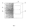
Als Beispiel kann angenommen werden, dass eine einfache Kante 3 eines hellen Objektes 2 auf einem dunklen Hintergrund 1 entlang der Suchlinie 6 (Fig. 1) untersucht werden soll.By way of example, it may be assumed that a simple edge 3 of a bright object 2 is to be examined on a dark background 1 along the search line 6 (FIG. 1) .
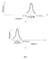
Mit Hilfe eines Histogramms (Fig. 2) kann sowohl die Objekthelligkeit I surf (Fig. 2, a) aus dem Testbereich 5 (Fig. 1) als auch die Hintergrundhelligkeit I bgrd (Fig. 2, b) aus dem Testbereich 4 (Fig. 1) ermittelt werden. By means of a histogram (Fig. 2) may be formed of the test area 5 (Fig. 1) both the object brightness I surf (Fig. 2, a) and the background brightness I bgrd (Fig. 2, b) from the test area 4 (Fig 1) .
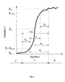
Die Standardabweichung σ f des Grauwertprofils, das entlang einer Suchlinie 6 beispielsweise von dem dunklen Hintergrundbereich 1 zum hellen Objektbereich 2 gewonnen wurde (Fig. 3), kann z.B. mit Hilfe der Methode der kleinsten Quadraten ermittelt werden.The standard deviation σ f of the gray value profile obtained along a search line 6, for example, from the dark background region 1 to the bright object region 2 ( FIG. 3 ), can be determined, for example, by means of the least squares method.
Um die Grenzwerte für die Objekt- und Hintergrundhelligkeit sowie für die Schärfe des Verfahrens, das an einer typischen Kante durchgeführt werden kann, zum Selbsttest eines Bildverarbeitungssystems zu definieren, soll zuerst ein Verfahren zur Kantensuche beschrieben werden, das dem Selbsttest zugrunde liegt.To set the limits for the subject and background brightness as well as the sharpness of the Method that can be performed on a typical edge, to self-test one To define an image processing system, a method for edge search will first be described that underlies the self-test.
Wie bereits oben begründet wurde, weist das Histogramm sowie das Grauwertprofil ein Gaußsches bzw. ein aus mehreren Gaußverteilungen resultierendes Profil auf. Das bedeutet, dass diese Kurven eine Normalverteilung nach Gauß und damit eine exponentielle Funktion darstellen und deshalb bestimmte Verhältnisse zwischen charakteristischen Punkten besitzen.As already explained above, the histogram and the gray-scale profile have one Gaussian or a profile resulting from several Gaussian distributions. It means that these curves represent a Gaussian normal distribution and thus an exponential function and therefore have certain relationships between characteristic points.
Das Grauwertprofil kann als Gaußsches Profil folgendermaßen beschrieben werden:
- I(x) -
- aktuelle Helligkeit, die der zu untersuchende Punkt auf der Kante aufweist, der sich in der Entfernung x vom Profilmaximum befindet;
- I surf -
- Objekthelligkeit, die auf dem Profilmaximum erstmalig und sicher auftritt;
- x -
- die Entfernung des zu untersuchenden Punktes von dem Punkt, der das Profilmaximum aufweist.
- I ( x ) -
- actual brightness of the point to be examined on the edge located at the distance x from the profile maximum;
- I surf -
- Object brightness, which occurs for the first time and safely on the profile maximum;
- x -
- the distance of the point to be examined from the point having the profile maximum.
Die einfache Standardabweichung σ f ausgehend vom Maximum des Profils zeigt auf
einen Punkt, an dem das Grauwertprofil einen Wendepunkt I turn (turn point) besitzt. Hier kann
sich damit theoretisch eine Kante 3 befinden:
- I surf -
- die Objekthelligkeit;
- ξ1 -
- der Wendepunktkoeffizient:
- I surf -
- the object brightness;
- ξ 1 -
- the turning point coefficient:
Die zweifache Standardabweichung 2 σ f ausgehend vom Maximum des Profils zeigt auf
einen Punkt, an dem das Grauwertprofil die Intensität von dem Strahlrand hat und sich damit der
Hintergrund 1 befindet:
- ξ2 -
- der Randpunktkoeffizient:
- ξ 2 -
- the boundary point coefficient:
Der Abstand zwischen den Punkten, welche die Werte I turn und I bgrd aufweisen,
entspricht ebenso der Standardabweichung σ f und ist vom jeweiligen Grauwertprofil (Fig. 3)
streng abhängig. Das Verhältnis zwischen diesen Werten ist jedoch für alle möglichen
Grauwertprofile, die über eine Kante 3 verlaufen, konstant und stellt einen minimalen
Helligkeitsfaktor η0 dar. Nach (2) bis (5) gilt:
Damit stellt der Helligkeitsfaktor η0 ein minimales Verhältnis zwischen den Helligkeiten der erst möglichen Kantenposition 3 und dem Hintergrund 1 dar.Thus, the brightness factor η 0 represents a minimum ratio between the brightnesses of the first possible edge position 3 and the background 1 .
Um die Position der zu untersuchenden Kante 3 auf dem Grauwertprofil zu finden, soll eine Teststrecke definiert werden, mit der das Grauwertprofil abgesucht wird.In order to find the position of the edge 3 to be examined on the gray scale profile, a test section is to be defined with which the gray scale profile is searched.
Die Länge der Teststrecke L 0 darf dabei nicht kleiner als der Abstand zwischen dem
Wendepunkt I turn und dem Randpunkt (Hintergrundhelligkeit I bgrd ) sein, was der
Standardabweichung σ f des Grauwertprofils entspricht. Gleichzeitig darf die Teststrecke L 0
die doppelte Größe der Standardabweichung σ f nicht überschreiten. Sonst wird die Teststrecke
größer als der gesamte Übergangsbereich 7 zwischen dem Hintergrund 1 und dem Objekt 2
(Fig. 3). Dann kann die Kantensuche nur nach der kantenspezifischen minimalen
Helligkeitssteigung ΔI 0, ohne Berücksichtigung der kantenspezifischen minimalen Helligkeit
I 0, die eine wichtige Bedingung für die adaptive Kantenerkennung darstellt, durchgeführt
werden. Deshalb soll folgende Bedingung erfüllt werden:
Dies bedeutet, dass eine Kante 3 anwesend ist, solange die folgenden Bedingungen
innerhalb der Teststrecke L 0 erfüllt sind:
- I max -
- die lokale maximale Helligkeit innerhalb der Teststrecke L 0 ;
- I min -
- die lokale minimale Helligkeit innerhalb der Teststrecke L 0 ;
- ΔI
- die lokale Helligkeitssteigung innerhalb der Teststrecke L 0 ;
- η -
- der lokale Helligkeitsfaktor innerhalb der Teststrecke L 0 .
- I max -
- the local maximum brightness within the test distance L 0 ;
- I min -
- the local minimum brightness within the test distance L 0 ;
- Δ I
- the local brightness gradient within the test track L 0 ;
- η -
- the local brightness factor within the test distance L 0 .
Zur Bestimmung der Parameter I 0 und ΔI 0 werden folgende Grenzfälle betrachtet. Wenn
der Endpunkt der Teststrecke L 0 bereits die Objektoberfläche 2 erreicht hat:
Die lokale minimale Helligkeit I min entspricht dabei noch nicht der Objekthelligkeit
(I min < I surf ) aber nicht mehr der Hintergrundhelligkeit (I min > I bgrd ). Sie weist nun auf einen
Übergangsbereich 7 zwischen dem Hintergrund 1 und dem Objekt 2, in dem sich eine Kante 3
befinden kann, und bestimmt damit die minimale Helligkeit I 0. Die kantenspezifische minimale
Helligkeit I 0 kann dann mit Hilfe von (12) und (11) folgendermaßen berechnet werden:
Befindet sich der Endpunkt der Teststrecke L 0 bereits in einer Position, die der Helligkeit
I 0 entspricht, und der Startpunkt noch auf dem Hintergrund 1 , soll im Falle einer wirklichen
Kante erst die Bedingung (9) erfüllt sein. D.h. die Suche nach einer Kante darf nur dann
angefangen werden, wenn die lokale Helligkeitssteigung ΔI innerhalb der Teststrecke L 0 die
kantenspezifische minimale Helligkeitssteigung ΔI 0 erreicht. Unter der Annahme, dass der
Startpunkt der Teststrecke L 0 sich im günstigsten Fall in einer Position befindet, die den
Helligkeitswert null aufweist, kann die kantenspezifische minimale Helligkeitssteigung ΔI 0, die
die Startbedingungen für die Kantensuche bestimmt, folgendermaßen definiert werden:
Damit kann eine Kante 3 zwischen den zwei folgenden Positionen und nur dort vorhanden sein. Die erste Position entspricht dem Endpunkt der Teststrecke L 0, wenn die Bedingungen (8) und (9) zum ersten Mal innerhalb der Teststrecke L 0 gleichzeitig erfüllt sind. Die zweite Position entspricht dem Startpunkt der Teststrecke L 0, wenn die Bedingungen (8) und (9) zum letzten Mal innerhalb der Teststrecke L 0 gleichzeitig erfüllt sind.Thus, an edge 3 between the two following positions and only exist there. The first position corresponds to the end point of the test track L 0 when the conditions (8) and (9) are fulfilled simultaneously for the first time within the test track L 0 . The second position corresponds to the starting point of the test track L 0 when the conditions (8) and (9) for the last time within the test track L 0 are fulfilled simultaneously.
Da das Grauwertprofil eine Gaußsche Funktion darstellt, folgt aus (13) und (1) unter der
Annahme, dass der Endpunkt der Teststrecke L 0 die Helligkeit I surf und der Startpunkt die
Helligkeit I 0 besitzt:
Aus dem Grauwertprofil (Fig. 3) kann mit Hilfe bekannter konventioneller Rechenmethoden, z.B. die Methode der kleinsten Quadrate, die Standardabweichung σ f dieses Profils als Gaußschen Profils ermittelt werden.From the gray value profile (FIG. 3) , the standard deviation σ f of this profile can be determined as Gaussian profile using known conventional calculation methods, for example the method of least squares.
Eine weitere Möglichkeit die Standardabweichung σ f des Grauwertprofils mit einer größeren Sicherheit und Genauigkeit zu ermitteln, besteht darin, zusätzliche Parameter des Grauwertprofils zu benutzen. Zu diesen Parametern gehören der untere Helligkeitsschwellwert I sprt_dark und der obere Helligkeitsschwellwert I sprt_light sowie der untere Sicherheitsabstand δ dark und der obere Sicherheitsabstand δ light (Fig. 3), die diese Helligkeitsschwellwerte bestimmen.Another possibility to determine the standard deviation σ f of the gray value profile with greater reliability and accuracy is to use additional parameters of the gray value profile. These parameters include the lower brightness threshold value I sprt_dark and the upper brightness threshold value I sprt_light as well as the lower safety distance δ dark and the upper safety distance δ light ( FIG. 3 ) which determine these brightness threshold values .
Der untere Helligkeitsschwellwert I sprt_dark und der obere Helligkeitsschwellwert I sprt_light trennen den Übergangsbereich 7 zwischen dem Objekt 2 und dem Hintergrund 1 auf dem Grauwertprofil (Fig. 3) von den restlichen Bereichen, die mit möglichen Störungen belastet sein können. Dies erlaubt eine sichere Kurvendiskussion, die beispielsweise für die Ermittlung der Standardabweichung σ f der Kurve benötigt wird. The lower brightness threshold value I sprt_dark and the upper brightness threshold value I sprt_light separate the transitional area 7 between the object 2 and the background 1 on the gray value profile (FIG. 3) from the remaining areas that may be subject to potential interference. This allows a safe curve discussion, which is needed, for example, to determine the standard deviation σ f of the curve.
Die Schwellwerte I sprt_dark und I spr_light können folgendermaßen definiert werden. Die
kantenspezifische minimale Helligkeit I 0 soll größer sein als die möglichen Abweichungen von
der Hintergrundhelligkeit I bgrd nach oben, die vom Rauschen verursacht werden können (Fig. 3),
und gleichzeitig die kantenspezifische minimale Helligkeitssteigung ΔI 0 gewährleisten, die vom
minimalen Helligkeitsfaktor η0 und von der Objekthelligkeit I surf abhängig ist. Deswegen kann
der untere Helligkeitsschwellwert I sprt_dark als die kantenspezifische minimale Helligkeit I 0
(Fig. 3) angenommen werden. Nach (13) gilt:
Der Wertbereich [I bgrd - I sprt_dark ] kann als Sicherheitszone im Hintergrundbereich mit dem Sicherheitsabstand δ dark zwischen dem Hintergrund 1 und der Stelle, ab der eine Kante 3 vorhanden sein kann, für die Kurvendiskussion des Grauwertprofils (Fig. 3) dienen.The value range [I bgrd - I sprt_dark] can as a safety zone in the background region with the safety distance δ dark between the background 1 and the location may be provided from the one edge 3, for the curve discussion of the gray value profile (Fig. 3) are used.
Der Wertbereich [I sprt_light - I surf ] kann analog dazu als Sicherheitszone im Objektbereich
mit dem Sicherheitsabstand δ light zwischen der Stelle, ab der eine Kante 3 nicht mehr vorhanden
sein kann, und dem Objekt 2 für die Kurvendiskussion des Grauwertprofils (Fig. 3) dienen.
Dabei kann die kantenspezifische minimale Helligkeitssteigung ΔI 0 den notwendigen
Unterschied zwischen der Objekthelligkeit I surf und dem oberen Helligkeitsschwellwert I sprt_light
gewährleisten:
Die Standardabweichung σ f kann auch durch eine Hilfstrecke l 0 berechnet werden, die
dem Abstand zwischen den Positionen entspricht, an denen das Profil zuerst den Wert I sprt_dark
und zuerst den Wert I sprt_light aufweist. Da das Grauwertprofil eine Gaußsche Funktion darstellt,
gilt nach (19) und (1):
Nun können die Grenzwerte für die Objekthelligkeit I surf und Hintergrundhelligkeit I bgrd sowie für die Objekthomogenität H surf und die Schärfe σ f des Verfahrens zu einem Selbsttest eines Bildverarbeitungssystems definiert werden.Now, the limits for the object brightness I surf and the background brightness I bgrd and for the object homogeneity H surf and the sharpness σ f of the method to a self-test of an image processing system can be defined.
Falls die Bedingung (10) für die Objekthelligkeit I surf und Hintergrundhelligkeit I bgrd erfüllt ist, unterscheidet sich die Objekthelligkeit I surf von der Hintergrundhelligkeit I bgrd genügend, um eine zwischen dem Objekt 2 und dem Hintergrund 1 entstehende Kante 3 sicher erkennen zu können. Dann darf das zu untersuchende Objekt 2 als eine strahlende Quelle angenommen werden.If the condition (10) for the object brightness I surf and the background brightness I bgrd is satisfied, the object brightness I surf differs from the background brightness I bgrd sufficiently to reliably detect an edge 3 arising between the object 2 and the background 1 . Then the object 2 to be examined may be assumed to be a radiating source.
Daraus folgt, dass die dynamische obere Grenze der Hintergrundhelligkeit I bgrd_max nach
(10), (15) und (16) folgendermaßen definiert werden kann:
Falls aber:
Aus (27) und (14) folgt:
Damit kann ein zulässiger maximaler Wert I bgrd_max für die Hintergrundhelligkeit
folgendermaßen definiert werden:
Die absolut maximale Helligkeit des Objektes 2 wird allerdings durch den Wert I max_abs begrenzt, den ein Aufnahmesensor maximal aufweisen kann (z.B. 255 bei Vollaussteuerung und 8-bit Quantisiereung des Sensors).However, the absolute maximum brightness of the object 2 is limited by the value I max_ abs , which a recording sensor can maximally have (eg 255 with full modulation and 8-bit quantization of the sensor).
Nach (26) weist die entsprechende Hintergrundhelligkeit I bgrd_max einen Wert auf, der
gleichzeitig die Objekthelligkeit I surf von unten begrenzt. Damit kann die absolut minimale
zulässige Objekthelligkeit I surf_min, die nie erreicht werden darf, folgendermaßen definiert
werden:
Dementsprechend kann die Objekthomogenität H surf und die Hintergrundhomogenität
H bgrd definiert werden:
- σ I
surf - - die Standardabweichung der Gaußförmigen Histogrammkurve des Objektes;
- σ I
bgrd - - die Standardabweichung der Gaußförmigen Histogrammkurve des Hintergrundes.
- σ I
surf - - the standard deviation of the Gaussian histogram curve of the object;
- σ I
bgrd - - the standard deviation of the Gaussian histogram curve of the background.
Die obengenannten Bedingungen für einen Selbsttest wurden für ein Objekt 2 und einen
Hintergrund 1 definiert, die eine homogene Oberfläche aufweisen und damit eine absolut
maximale Homogenität haben:
Falls aber das Objekt 2 und der Hintergrund 1 keine homogene Oberfläche aufweisen, soll eine minimale Grenze der Oberflächenhomogenität H min definiert werden, die noch eine Kantenerkennung gewährleisten kann.If, however, the object 2 and the background 1 do not have a homogeneous surface, a minimum limit of the surface homogeneity H min should be defined which can still guarantee edge detection.
Die untere Grenze des Homogenitätsbereiches des Objektes [I surf - 2 * σ I
Aufgrund des normierten Charakters der Homogenität kann für die Hintergrundhomogenität H bgrd ebenfalls denselben Wert nach (38) als minimale zulässige Homogenität H min angenommen werden.Because of the normalized character of the homogeneity, the same value according to (38) can also be assumed for the background homogeneity H bgrd as the minimum permissible homogeneity H min .
Die Standardabweichung σ I
Für inhomogenen Oberflächen verschärfen sich die Testbedingungen für die Beleuchtung,
weil bei der Definition des zulässigen Bereiches der Helligkeit sowohl des Objektes 2 als auch
des Hintergrundes 1 der entsprechende Homogenitätsbereich [I Gauss - 2 * σ I
Erfindungsgemäß können die entsprechenden Grenzwerte für I surf nach (32) und (31)
sowie für I bgrd nach (26) mit Berücksichtigung des Wertes 2 * σ I
Diese Grenzwerte können und sollen dynamisch aus dem zu untersuchenden Bild ermittelt und zur Kontrolle benutzt werden.These limits can and should be dynamic from the image to be examined determined and used for control.
Allerdings kann eine wesentlich größere Sicherheit erreicht werden, falls man für den
Selbsttest die minimale zulässige Homogenität H min als maßgebend vorgibt. Dabei soll der
Korrekturterm (+ 2 * σ I
Für I bgrd sieht die Bedingung (26) mit Berücksichtigung der maximalen
Homogenitätsbereiche (Fig. 2) folgendermaßen aus:
Damit kann der entsprechende maximale Grenzwert I bgrd_max nach (44) fest definiert
werden:
- für ein homogenes Objekt 2 und einen homogenen Hintergrund 1 nach (26):
- für ein inhomogenes Objekt 2 und einen inhomogenen Hintergrund 1 nach (41):
- for a homogeneous object 2 and a homogeneous background 1 according to (26):
- for an inhomogeneous object 2 and an inhomogeneous background 1 according to (41):
Daraus folgt:
- für ein homogenes Objekt 2 und einen homogenen Hintergrund 1 nach (28)-(30):
- für ein inhomogenes Objekt 2 und einen inhomogenen Hintergrund 1:
- falls die Beleuchtung mit einem dynamisch korrigierten Grenzwert kontrolliert
wird, nach (14), (27), (35) und (37):
- falls die Beleuchtung mit einem Grenzwert kontrolliert wird, der mit einem festen
Koeffizient korrigiert ist, nach (27) mit Berücksichtigung (14) und der maximalen
Homogenitätsbereiche (Fig. 2):
- falls die Beleuchtung mit einem dynamisch korrigierten Grenzwert kontrolliert
wird, nach (14), (27), (35) und (37):
- for a homogeneous object 2 and a homogeneous background 1 according to (28) - (30):
- for an inhomogeneous object 2 and an inhomogeneous background 1 :
- if the illumination is controlled with a dynamically corrected threshold, according to (14), (27), (35) and (37):
- if the illumination is controlled with a threshold value corrected with a fixed coefficient, according to (27) with consideration (14) and the maximum homogeneity ranges (Figure 2):
- if the illumination is controlled with a dynamically corrected threshold, according to (14), (27), (35) and (37):
Daraus folgt:
Desweiteren soll überprüft werden, ob die zu untersuchende Musterkante scharf genug abgebildet ist. Die Standardabweichung σ f des Grauwertprofils (Fig. 3), die mit Hilfe bekannter konventioneller Rechenmethoden, z.B. die Methode der kleinsten Quadrate, ermittelt werden soll, kann für die Schärfenkontrolle benutzt werden.Furthermore, it should be checked whether the sample edge to be examined is shown sharp enough. The standard deviation σ f of the gray value profile (FIG. 3), which is to be determined by means of known conventional calculation methods, eg the method of the least squares, can be used for the sharpness control.
Solange gilt:
Allerdings kann die Hilfsteststrecke l 0, die man als Abstand zwischen den Positionen auf dem Grauwertprofil (Fig. 3) ermittelt, an denen das Profil zuerst den Wert I sprt_dark und zuerst den Wert I sprt_light aufweist, nach (25) ohne einen Verallgemeinerungsverlust als Standardabweichung σ f des Gaußförmigen Grauwertprofils angenommen werden.However, the auxiliary test distance l 0 , which is obtained as the distance between the positions on the gray scale profile (Figure 3) , where the profile first has the value I sprt_dark and first the value I sprt_light , according to (25) without a generalization loss as the standard deviation σ f of the Gaussian grayscale profile.
Die Werte I sprt_light und I sprt_dark können ebenso benutzt werden, um auf dem
Helligkeitshistogramm des Objektes (Fig. 2, a) bzw. des Hintergrundes (Fig. 2, b) einen Bereich
abzutrennen, auf dem die Standardabweichung σ I
Damit lässt sich ein Selbsttest, der eine sichere und flexible Beleuchtungs- und Schärfenkontrolle eines Bildes gewährleistet, so durchführen dass die auf dem Bild vorhandenen Kanten explizit erkannt werden können. This allows a self-test that provides a safe and flexible lighting and Ensuring sharpness control of an image, so perform that on the image Edges can be recognized explicitly.
- 11
- Hintergrundbackground
- 22
- Objektobject
- 33
- Kante zwischen dem Hintergrund und dem ObjektEdge between the background and the object
- 44
- Testbereich auf dem HintergrundTest area on the background
- 55
- Testbereich auf dem ObjektTest area on the object
- 66
- Suchliniesearch line
- 77
- Übergangsbereich zwischen dem Hintergrund und dem ObjektTransition area between the background and the object
Claims (10)
Patentgemäß ist der Selbsttest folgendermaßen durchzuführen.
Aus dem Histogramm des zu untersuchenden Testbereiches 4 findet man die Hintergrundhelligkeit I bgrd und aus dem Histogramm des zu untersuchenden Testbereiches 5 -die Objekthelligkeit I surf , wobei diese Helligkeiten als der am häufigsten vorkommende Wert des entsprechenden Histogramms ermittelt werden sollen.
Dabei geht man davon aus, dass das Objekt 2 beispielsweise immer heller als der Hintergrund 1 ist. Ansonsten sollen die Rollen des Objektes und des Hintergrundes vertauscht werden.
Desweiteren geht man davon aus, dass das Objekt 2 und der Hintergrund 1 homogen sind.
Anhand dieser gewonnenen Merkmale soll zuerst die Beleuchtung des aufgenommenen Bildes kontrolliert werden, wobei die Helligkeitswerte I bgrd und I surf nach folgenden Bedingungen überprüft werden:
- I surf_min -
- die untere Grenze des zulässigen Helligkeitsbereiches des Objektes:
- I max_abs -
- die absolut maximale Helligkeit (z.B. 255 bei Vollaussteuerung und 8-bit Quantisiereung), die ein Sensor aufweisen kann;
- I surf_max -
- die obere Grenze des zulässigen Helligkeitsbereiches des Objektes, die der
oberen Grenze des Linearitätsbereiches der Kamera I lin (z.B. 220)
entspricht:
- I bgrd_max -
- die obere Grenze des zulässigen Helligkeitsbereiches des Hintergrundes, die
dynamisch ermittelt werden soll:
- η0 -
- der Helligkeitsfaktor, der eine allgemeine grundlegenden Konstante für
die Kantenerkennung darstellt:
- ξ1 -
- der Wendepunktkoeffizient, der die Intensität eines Strahles am Wendepunkt
seiner Intensitätsverteilung bestimmt:
- ξ2 -
- der Randpunktkoeffizient, der die Intensität eines Strahles an seinem Rand
bestimmt:
Aus dem Grauwertprofil kann mit Hilfe bekannter konventioneller Rechenmethoden, z.B. die Methode der kleinsten Quadrate, die Standardabweichung σ f ermittelt werden.
Erfindungsgemäß soll diese mit der maximalen zulässigen Standardabweichung σ f_max verglichen werden, die im Voraus folgendermaßen berechnet wird:
- σ f_min -
- die Standardabweichung des Grauwertprofils an der Kante 3 bei einem am
schärfsten aufgenommenen Bild, die auch aus dem Mittelwert der an
mehreren Stellen der zu untersuchenden Kante 3 ermittelten Werte
σ f berechnet werden kann; - Δσ f -
- zulässige Abweichung der Standardabweichung σ f von minimalem Wert σ f_min, z.B. 0.5, die nach Erfahrungswerten festgestellt werden muss.
According to the patent, the self-test is to be carried out as follows.
From the histogram of the test area 4 to be examined, one finds the background brightness I bgrd and from the histogram of the test area 5 to be examined-the object brightness I surf , whereby these brightnesses are to be determined as the most frequently occurring value of the corresponding histogram.
It is assumed that the object 2 is always brighter than the background 1 , for example. Otherwise, the roles of the object and the background should be reversed.
Furthermore, it is assumed that the object 2 and the background 1 are homogeneous.
On the basis of these characteristics, the illumination of the recorded image should first be checked, whereby the brightness values I bgrd and I surf are checked according to the following conditions:
- I surf _min -
- the lower limit of the permitted brightness range of the object:
- I max_ abs -
- the absolute maximum brightness (eg 255 at full scale and 8-bit quantization) that a sensor can have;
- I surf _max -
- the upper limit of the permissible brightness range of the object, which corresponds to the upper limit of the linearity range of the camera I lin (eg 220):
- I bgrd _max -
- the upper limit of the permitted brightness range of the background, which should be determined dynamically:
- η 0 -
- the brightness factor, which is a general basic constant for edge detection:
- ξ 1 -
- the inflection point coefficient, which determines the intensity of a ray at the inflection point of its intensity distribution:
- ξ 2 -
- the edge point coefficient, which determines the intensity of a beam at its edge:
From the gray value profile, the standard deviation σ f can be determined by means of known conventional calculation methods, eg the method of the least squares.
According to the invention, this is to be compared with the maximum permissible standard deviation σ f _max , which is calculated in advance as follows:
- σ f _min -
- the standard deviation of the gray value profile at the edge 3 in the case of the most sharply recorded image, which also includes the mean value of the values determined at several points of the edge 3 to be examined
σ f can be calculated; - Δσ f -
- permissible deviation of the standard deviation σ f from minimum value σ f _min , eg 0.5, which must be determined according to empirical values.
- σ I
surf - - die Standardabweichung der Gaußförmigen Histogrammkurve des Objektes;
- σ I
bgrd - - die Standardabweichung der Gaußförmigen Histogrammkurve des Hintergrundes;
- σ I
surf - - the standard deviation of the Gaussian histogram curve of the object;
- σ I
bgrd - - the standard deviation of the Gaussian histogram curve of the background;
Applications Claiming Priority (2)
| Application Number | Priority Date | Filing Date | Title |
|---|---|---|---|
| DE10326032 | 2003-06-10 | ||
| DE10326032A DE10326032B4 (en) | 2003-06-10 | 2003-06-10 | Method for self-testing an image processing system |
Publications (2)
| Publication Number | Publication Date |
|---|---|
| EP1505541A2 true EP1505541A2 (en) | 2005-02-09 |
| EP1505541A3 EP1505541A3 (en) | 2006-04-05 |
Family
ID=33520515
Family Applications (1)
| Application Number | Title | Priority Date | Filing Date |
|---|---|---|---|
| EP04013429A Withdrawn EP1505541A3 (en) | 2003-06-10 | 2004-06-08 | Self-testing method for an image processing system |
Country Status (2)
| Country | Link |
|---|---|
| EP (1) | EP1505541A3 (en) |
| DE (1) | DE10326032B4 (en) |
Cited By (2)
| Publication number | Priority date | Publication date | Assignee | Title |
|---|---|---|---|---|
| WO2010124667A1 (en) * | 2009-04-28 | 2010-11-04 | Emin Luis Aksoy | Apparatus for detecting a maximum resolution of the details of a digital image |
| CN109919969A (en) * | 2019-01-22 | 2019-06-21 | 广东工业大学 | A method of realizing that visual movement controls using depth convolutional neural networks |
Families Citing this family (3)
| Publication number | Priority date | Publication date | Assignee | Title |
|---|---|---|---|---|
| DE102006048767B4 (en) * | 2006-10-12 | 2008-10-02 | Thermosensorik Gmbh | Device for adjusting and calibrating an infrared system |
| DE102007045277A1 (en) * | 2007-09-18 | 2009-04-02 | Technische Universität Ilmenau | Method for determining the edge location when probing in reflected light in optical length measuring technology |
| DE102008025896A1 (en) * | 2008-05-23 | 2009-11-26 | Landesamt für Mess- und Eichwesen Thüringen | Method for determining the measurement uncertainty in geometry measurement |
Citations (2)
| Publication number | Priority date | Publication date | Assignee | Title |
|---|---|---|---|---|
| US4859850A (en) * | 1987-01-12 | 1989-08-22 | Fuji Photo Film Co., Ltd. | Irradiation field recognizing method, and method of adjusting image processing conditions using the same |
| US20020114015A1 (en) * | 2000-12-21 | 2002-08-22 | Shinichi Fujii | Apparatus and method for controlling optical system |
Family Cites Families (5)
| Publication number | Priority date | Publication date | Assignee | Title |
|---|---|---|---|---|
| KR940007346B1 (en) * | 1991-03-28 | 1994-08-13 | 삼성전자 주식회사 | Edge detection apparatus for image processing system |
| DE4435796C1 (en) * | 1994-10-06 | 1995-12-07 | Siemens Ag | Automatic digital detection of edges and diameter in pref. X=ray images |
| CA2211258C (en) * | 1995-01-31 | 2000-12-26 | United Parcel Service Of America, Inc. | Method and apparatus for separating foreground from background in images containing text |
| JPH096957A (en) * | 1995-06-23 | 1997-01-10 | Toshiba Corp | Binarization method for density image and image binarization device |
| DE19902401C2 (en) * | 1999-01-22 | 2001-02-01 | Wohlenberg Schneidesysteme Gmb | Method and device for determining the geometry of sheet-like material or stacks thereof |
-
2003
- 2003-06-10 DE DE10326032A patent/DE10326032B4/en not_active Withdrawn - After Issue
-
2004
- 2004-06-08 EP EP04013429A patent/EP1505541A3/en not_active Withdrawn
Patent Citations (2)
| Publication number | Priority date | Publication date | Assignee | Title |
|---|---|---|---|---|
| US4859850A (en) * | 1987-01-12 | 1989-08-22 | Fuji Photo Film Co., Ltd. | Irradiation field recognizing method, and method of adjusting image processing conditions using the same |
| US20020114015A1 (en) * | 2000-12-21 | 2002-08-22 | Shinichi Fujii | Apparatus and method for controlling optical system |
Non-Patent Citations (2)
| Title |
|---|
| MURINO V ET AL: "ADAPTIVE CAMERA REGULATION FOR INVESTIGATION OF REAL SCENES" IEEE TRANSACTIONS ON INDUSTRIAL ELECTRONICS, IEEE SERVICE CENTER, PISCATAWAY, NJ, US, Bd. 43, Nr. 5, Oktober 1996 (1996-10), Seiten 588-599, XP000643558 ISSN: 0278-0046 * |
| MURINO V ET AL: "Real-time adaptive regulation of a visual camera for automatic investigation of changing environments" INDUSTRIAL ELECTRONICS, CONTROL, AND INSTRUMENTATION, 1993. PROCEEDINGS OF THE IECON '93., INTERNATIONAL CONFERENCE ON MAUI, HI, USA 15-19 NOV. 1993, NEW YORK, NY, USA,IEEE, 15. November 1993 (1993-11-15), Seiten 1633-1638, XP010109265 ISBN: 0-7803-0891-3 * |
Cited By (3)
| Publication number | Priority date | Publication date | Assignee | Title |
|---|---|---|---|---|
| WO2010124667A1 (en) * | 2009-04-28 | 2010-11-04 | Emin Luis Aksoy | Apparatus for detecting a maximum resolution of the details of a digital image |
| CN109919969A (en) * | 2019-01-22 | 2019-06-21 | 广东工业大学 | A method of realizing that visual movement controls using depth convolutional neural networks |
| CN109919969B (en) * | 2019-01-22 | 2022-11-22 | 广东工业大学 | Method for realizing visual motion control by utilizing deep convolutional neural network |
Also Published As
| Publication number | Publication date |
|---|---|
| DE10326032B4 (en) | 2006-08-31 |
| EP1505541A3 (en) | 2006-04-05 |
| DE10326032A1 (en) | 2005-01-13 |
Similar Documents
| Publication | Publication Date | Title |
|---|---|---|
| DE10326035B4 (en) | Method for adaptive error detection on a structured surface | |
| DE102011081668B4 (en) | Apparatus and method for determining the shape of the end of a weld | |
| DE19521346C2 (en) | Image examination / recognition method, method used therein for generating reference data and devices therefor | |
| DE3047490C2 (en) | ||
| DE3937950A1 (en) | METHOD FOR CHECKING OPTICAL SURFACES | |
| EP1609119A2 (en) | Methods for qualitative evaluation of a material with at least one identification characteristic | |
| DE10326033B4 (en) | Method for adaptive error detection on an inhomogeneous surface | |
| DE10326032B4 (en) | Method for self-testing an image processing system | |
| DE4105516A1 (en) | METHOD AND DEVICE FOR FILTERING SIGNALS | |
| EP3655920B1 (en) | Method and device for analysing image sections for a correspondence calculation | |
| DE19636864C1 (en) | Video signal processing device for length detection of transverse scratches | |
| DE10326031B4 (en) | Method for adaptive edge detection | |
| DE69923120T2 (en) | Apparatus and method for detecting light or dark spots | |
| DE19636865C1 (en) | Processing device for detecting inclined scratches in video signals from film scanner | |
| EP3142068B1 (en) | Method for three-dimensional recording of objects | |
| EP1139285B1 (en) | Method and apparatus for testing or inspection of articles | |
| DE10066189B4 (en) | Detecting stationary or moving objects such as images or texts by selecting search section within search window | |
| DE102021200821B3 (en) | Generation of training data for two-dimensional scans of a ground radar system | |
| DE10024559B4 (en) | Object recognition method | |
| EP1567991B1 (en) | Method and device for verifying valuable documents | |
| DE3406694C2 (en) | ||
| EP3516634B1 (en) | Method and device for detecting color fading on a banknote, and value-document processing system | |
| DE102018103861B3 (en) | Method for determining an evaluation area in an image of a vehicle camera by means of line-based image processing | |
| DD298158A5 (en) | METHOD FOR THE FAST AUTOMATIC DETECTION OF ERRORS IN UNIFORM, UNMANNED OR LOW PATTERNED TRAINS | |
| DE19810162C2 (en) | Process for image analysis according to stochastic properties |
Legal Events
| Date | Code | Title | Description |
|---|---|---|---|
| PUAI | Public reference made under article 153(3) epc to a published international application that has entered the european phase |
Free format text: ORIGINAL CODE: 0009012 |
|
| 17P | Request for examination filed |
Effective date: 20040701 |
|
| AK | Designated contracting states |
Kind code of ref document: A2 Designated state(s): AT BE BG CH CY CZ DE DK EE ES FI FR GB GR HU IE IT LI LU MC NL PL PT RO SE SI SK TR |
|
| AX | Request for extension of the european patent |
Extension state: AL HR LT LV MK |
|
| PUAL | Search report despatched |
Free format text: ORIGINAL CODE: 0009013 |
|
| AK | Designated contracting states |
Kind code of ref document: A3 Designated state(s): AT BE BG CH CY CZ DE DK EE ES FI FR GB GR HU IE IT LI LU MC NL PL PT RO SE SI SK TR |
|
| AX | Request for extension of the european patent |
Extension state: AL HR LT LV MK |
|
| AKX | Designation fees paid |
Designated state(s): AT BE BG CH CY CZ DE DK EE ES FI FR GB GR HU IE IT LI LU MC NL PL PT RO SE SI SK TR |
|
| 17Q | First examination report despatched |
Effective date: 20090316 |
|
| STAA | Information on the status of an ep patent application or granted ep patent |
Free format text: STATUS: EXAMINATION IS IN PROGRESS |
|
| STAA | Information on the status of an ep patent application or granted ep patent |
Free format text: STATUS: THE APPLICATION IS DEEMED TO BE WITHDRAWN |
|
| 18D | Application deemed to be withdrawn |
Effective date: 20090929 |