DE10326033B4 - Method for adaptive error detection on an inhomogeneous surface - Google Patents
Method for adaptive error detection on an inhomogeneous surface Download PDFInfo
- Publication number
- DE10326033B4 DE10326033B4 DE10326033A DE10326033A DE10326033B4 DE 10326033 B4 DE10326033 B4 DE 10326033B4 DE 10326033 A DE10326033 A DE 10326033A DE 10326033 A DE10326033 A DE 10326033A DE 10326033 B4 DE10326033 B4 DE 10326033B4
- Authority
- DE
- Germany
- Prior art keywords
- loc
- edge
- error
- brightness
- maximum
- Prior art date
- Legal status (The legal status is an assumption and is not a legal conclusion. Google has not performed a legal analysis and makes no representation as to the accuracy of the status listed.)
- Withdrawn - After Issue
Links
Classifications
-
- G—PHYSICS
- G06—COMPUTING; CALCULATING OR COUNTING
- G06T—IMAGE DATA PROCESSING OR GENERATION, IN GENERAL
- G06T7/00—Image analysis
- G06T7/0002—Inspection of images, e.g. flaw detection
- G06T7/0004—Industrial image inspection
-
- G—PHYSICS
- G06—COMPUTING; CALCULATING OR COUNTING
- G06T—IMAGE DATA PROCESSING OR GENERATION, IN GENERAL
- G06T7/00—Image analysis
- G06T7/10—Segmentation; Edge detection
- G06T7/13—Edge detection
-
- G—PHYSICS
- G06—COMPUTING; CALCULATING OR COUNTING
- G06T—IMAGE DATA PROCESSING OR GENERATION, IN GENERAL
- G06T2207/00—Indexing scheme for image analysis or image enhancement
- G06T2207/20—Special algorithmic details
- G06T2207/20004—Adaptive image processing
- G06T2207/20012—Locally adaptive
-
- G—PHYSICS
- G06—COMPUTING; CALCULATING OR COUNTING
- G06T—IMAGE DATA PROCESSING OR GENERATION, IN GENERAL
- G06T2207/00—Indexing scheme for image analysis or image enhancement
- G06T2207/30—Subject of image; Context of image processing
- G06T2207/30108—Industrial image inspection
- G06T2207/30136—Metal
Abstract
Verfahren
zur adaptiven Erkennung eines Fehlers 6 auf einer inhomogenen Oberfläche 2, z.B. einer
Metalloberfläche,
der auf einem mit einem Kamerasensor aufgenommenen Bild in einem
Testbereich 4 mit Hilfe kantenbasierender Segmentierungsmethoden
gesucht wird, dadurch gekennzeichnet, dass, falls im Grauwertprofil,
das entlang einer Suchlinie 5 gewonnen wurde, mit der ein Testbereich
4 abgetastet werden soll, eine Strecke vorhanden ist, die von links
und von rechts mit einer Kante (Maximum-Minimum- bzw. Minimum-Maximum-Paar) abgegrenzt
ist, an deren die folgenden Bedingungen gleichzeitig erfüllt sind:
Imin_loc_left die
Helligkeit, die das lokale Minimum links aufweist;
Iedge_loc_left die maximale Helligkeit, die
ein Fehler an der linken Kante aufweisen darf:
I min_loc_left the brightness that has the local minimum left;
I edge_loc_left the maximum brightness that may have a left edge error:

Description
Die Erfindung betrifft ein Verfahren gemäß dem Oberbegriff des Anspruchs 1.The The invention relates to a method according to the preamble of the claim 1.
Insbesondere bezieht sich die Erfindung auf die Erkennung eines Fehlers auf einer inhomogenen Oberfläche, z.B. einer Metalloberfläche, die als Licht-und-Schatten-Bild mittels eines Bildverarbeitungssystems gewonnen wird. Unabhängig von den aufgetretenen globalen und lokalen Oberflächenhelligkeitsschwankungen gewährleistet das Verfahren eine einwandfreie Erkennung aller vorhandenen Fehler, wobei alle benötigten Parameter angepasst zu lokalen Helligkeitsbedingungen aus dem zu untersuchenden Bild dynamisch ermittelt werden.Especially The invention relates to the detection of a fault on a inhomogeneous surface, e.g. a metal surface, as a light-and-shade image using an image processing system is won. Independently from the occurred global and local surface brightness variations guaranteed the procedure is a perfect recognition of all existing errors, where all needed Parameters adapted to local brightness conditions from be determined dynamically.
Eine der bekanntesten Methoden der Bildverarbeitung, einen bestimmten Objekttyp auf einer Oberfläche zu erkennen, ist die Strukturanalyse (Frei konfigurierbare regionalbasierte Farbtexturanalyse zur automatischen Auswertung von Bild-Stichproben/A. Burmeister. – Arbeit zur Erlangung des Grades „Doktor-Ingenieur" – Der Technischen Fakultät der Universität Erlangen-Nürnberg; Erlangen, 1999). Sie stellt Hunderte, wenn nicht Tausende statistische Merkmale zur Verfügung, um ein Objekt zu beschreiben und damit wiedererkennen zu können.A the best known methods of image processing, a specific one Object type on a surface is the structural analysis (freely configurable regional based Color texture analysis for the automatic evaluation of image samples / A. Burmeister. - Job to obtain the degree "Doctor-Ingenieur" - The Technical Faculty of the University Erlangen-Nürnberg; Erlangen, 1999). It provides hundreds, if not thousands, statistical Features available, to describe an object and recognize it.
Diese
Merkmale berechnet man beispielsweise direkt aus dem zu untersuchenden
Bild oder aus einem Histogramm bzw. einem Gradientbild (
Bei allen solchen Methoden werden jedoch die zu suchenden Objekte (Fehler) rein formalistisch behandelt, ohne ihre reellen Eigenschaften zu berücksichtigen. Deswegen versagt sie bei der Erkennung von nicht künstlichen Objekten, die nie identisch zum Referenz-Objekt sind und sich in einer imhomogenen Umgebung befinden. Dabei werden so genannte Pseudo-Fehler (reguläre Objekte als Fehler) massiv erkannt.at however, all such methods will cause the objects to be searched (errors) purely formalistically treated, without their real qualities consider. Therefore, it fails in the detection of non-artificial Objects that are never identical to the reference object and are in an imhomogeneous environment. In doing so, so-called pseudo-errors (regular objects as a mistake) massively recognized.
Darüber hinaus vergrößert sich die Anzahl der Merkmale, die man dabei verwendet, um die zu suchenden Objekte zu erkennen, so gewaltig, dass die Steuerung solcher Erkennungssysteme fast unmöglich ist. Mittlerweise werden bekanntermaßen schon über etwa anderthalbtausend Texturmerkmale zur Fehlererkennung verwendet (Automatische Extraktion von Festigkeits und optisch relevanten Merkmalen aus Farbbildern von Schnittholzflächen. – DGfH-Nr. F-98/01, Projektleitung: Prof. Dr.-Ing. Habil. S. Fuchs, Universität Dresden, Fakultät Informatik, Institut für künstliche Intelligenz, 2002).Furthermore increases the number of features you use to find the one you are looking for Recognizing objects so vast that controlling such recognition systems almost impossible is. In the meantime, as is well known, already over one and a half thousand Texture features used for error detection (Automatic Extraction of strength and optically relevant features from color images of sawn timber surfaces. - DGfH no. F-98/01, project leader: Prof. Dr.-Ing. Habil, S. Fuchs, University of Dresden, Faculty Computer Science, Institute of artificial Intelligence, 2002).
Die Unterstützung von neuronalen Netzen hilft dabei sehr wenig. Sie führt nur dazu, dass die sogenannten Merkmalswolken in einem mehrdimensionalen Merkmalsraum mit steigender Anzahl eingelernter Objekte immer mehr verschwimmen und die Fehlererkennungsleistung bzw. Pseudo-Fehler- die Erkennung der Pseudo-Fehler eines Bildverarbeitungssystems sich nur verschlechtert.The support of neural networks helps very little. It only leads to the fact that the so-called feature clouds in a multi-dimensional Feature space with increasing number of learned objects more and more and the error detection performance or pseudo-error the detection of pseudo-errors of an image processing system itself only worsened.
Eine andere Methode verwendet für die Erkennung eines Fehlers auf einem zu untersuchendem Bild die kantenbasierte Segmentierung (Digitale Bildverarbeitung/Bernd Jähre. – 4. Aufl. – Berlin, Heidelberg, etc.: Springer, 1997). Dabei spielt die Kantenerkennung eines Objektes eine zentrale Rolle.A other method used for the detection of an error on a picture to be examined the edge-based segmentation (Digital Image Processing / Bernd Jahre - 4th edition - Berlin, Heidelberg, etc .: Springer, 1997). The edge detection plays here an object a central role.
Es ist Stand der Technik, dass man für die generelle Kantensuche eine Umwandlung des gesamten Bildes in ein Kantenbild mit Hilfe verschiedener Kantenfilter (Digitale Bildverarbeitung/Bernd Jähne. – 4. Aufl. – Berlin, Heidelberg, etc.: Springer, 1997) benutzt.It is state of the art, that one for the general edge search a conversion of the whole picture into an edge picture with help various edge filters (Digital Image Processing / Bernd Jähne - 4th edition - Berlin, Heidelberg, etc .: Springer, 1997).
Neben dem erheblichen Rechenaufwand hat diese Methode den Nachteil, dass das Bild durch eine Filterung bearbeitet, d.h. geändert wird, was die Kantenerkennung selbst beeinflusst und damit das Ergebnis verfälscht. Dabei können manche Kanten wegen mangelhaften Kontrasts überhaupt nicht erkannt bzw. zufällige Stellen, die einen ausreichenden Beleuchtungsgradienten aufweisen, fälschlicherweise als Kanten erkannt werden.Next the considerable computational effort, this method has the disadvantage that the image is processed by filtering, i. will be changed, which affects the edge detection itself and thus falsifies the result. there can some edges because of poor contrast not recognized or random Locations that have sufficient illumination gradient, falsely be recognized as edges.
Ein
weiteres Verfahren (
Der
vorgegebene Schwellwert (
Den Schwellwert direkt aus dem Inhalt des aktuellen Bildes zu ermitteln, ist eine Möglichkeit, um das Verfahren für Objektsuche an das zu untersuchende Bild anzupassen.The Threshold value directly from the content of the current image, is a way to the procedure for Adjust the object search to the image to be examined.
Dafür benutzt
man z.B. ein Histogramm (
Wenn
das Histogramm jedoch für
große
Bildbereiche bestimmt wird, neigen Kanten dazu, verschmiert zu werden
oder sogar überhaupt
zu verschwinden. Umgekehrt, wenn der aufgeteilte Bereich zu klein
ist, kann er nicht sauber binarisiert werden. Der Prozess, mit dem
der binarisierende Bildbereich in geeignete Stücke zu unterteilen (
Eine
Reihe von Kandidatenbinärbilder
aufzunehmen und auszuwerten, welche mit fallenden bzw. mit steigenden
Schwellwerten erzeugt wurden, um den bestmöglichen Binarisierungsschwellwert
zu finden (
Darüber hinaus beeinflusst eine Binarisierung des Bildes die Objekterkennung und damit verfälscht sie, genauso wie jede andere Bildfilterung. Außerdem verursacht dieses Verfahren, bei dem es sich nur nach dem Grauwertunterschied handelt, eine massive Erkennung der Pseudo-Fehler. Deswegen soll die Kanten- sowie Objekterkennung am besten auf dem Originalgrauwertbild erfolgen.Furthermore a binarization of the image affects the object recognition and it falsifies it, just like any other image filtering. In addition, this process causes which is only after the gray value difference, a massive Detection of pseudo-errors. Therefore, the edge and object detection is best on the Original gray value image done.
Es ist ferner bekannt, dass man eine Kante aus einem Grauwertbild direkt mittels eines Kantenmodells ermitteln kann (Industrielle Bildverarbeitung/Christian Demant, Bernd Streicher-Abel, Peter Waszkewitz. – Berlin; Heidelberg: Springer, 1998). Das betrifft besonders den Fall, in dem der Ort der Kante bereits bekannt ist. Die Suche nach Kanten mit einem Kantenmodell erfolgt normalerweise auf Suchlinien in einer bestimmten Richtung.It It is also known that one edge from a gray scale image directly can determine by means of an edge model (Industrial image processing / Christian Demant, Bernd Streicher-Abel, Peter Waszkewitz. - Berlin; Heidelberg: Springer, 1998). This particularly concerns the case in which the place of the edge already known. The search for edges with an edge model is usually done on search lines in a particular direction.
Die Kriterien für die Detektierung einer Kante ergeben sich aus dem Grauwertprofil entlang dieser Suchlinie.The Criteria for the detection of an edge results from the gray value profile along this search line.
Dabei unterscheidet man zwei Kantenrichtungen: ansteigende und abfallende Kanten. Von einer abfallenden Kante spricht man, wenn das Grauwertprofil von hell nach dunkel verläuft, im umgekehrten Fall hat man eine ansteigende Kante vor sich.there a distinction is made between two edge directions: rising and falling Edge. A falling edge is called if the gray value profile from light to dark, in the opposite case you have a rising edge in front of you.
Ein typisches Verfahren benutzt folgende Parameter:
- • Kantenhöhe: Zur Detektierung einer gültigen Kante fordert man, dass eine bestimmte Mindestdifferenz der Grauwerte entlang der Suchlinie auftritt. Dies bezeichnet man als Kantenhöhe.
- • Kantenlänge: Die Kantenlänge gibt an, auf welcher Strecke die durch die Kantenhöhe festgestellte Mindestdifferenz der Grauwerte auftreten muss.
- • Edge height: To detect a valid edge, it is required that a certain minimum difference of gray values occur along the search line. This is called edge height.
- • Edge length: The edge length indicates at which distance the minimum difference of the gray values determined by the edge height must occur.
An diesem Verfahren, das als Stand der Technik gilt, ist nachteilig, dass die vorgegebene Kantenhöhe und Kantenlänge bei jedem zu untersuchenden Bild unverändert bleiben müssen, und damit keine dynamische Anpassung an das aktuelle Bild angeboten wird.At This method, which is considered as prior art, is disadvantageous, that the given edge height and edge length must remain unchanged for each image to be examined, and thus no dynamic adaptation to the current picture offered becomes.
Eine
andere Lösung
ist vom
Dabei benötigt man aber eine Musterkante, deren Profil weiter benutzt werden soll, und ebenso einen prozentualen Schwellwert als vorgegebenen Parameter. Deswegen bleibt dieses Verfahren vollständig objektspezifisch und bietet keine Anpassung an das zu untersuchende Bild.there needed but you have a pattern edge whose profile is to be used, and also a percentage threshold as the default parameter. Therefore, this procedure remains completely object specific and offers no adaptation to the image to be examined.
Zusammenfassend können die obengenannten Methoden keine flexible und gleichzeitig explizite Kantenerkennung auf einem zu untersuchenden Bild gewährleisten und deswegen auch nicht für eine sichere Fehlererkennung auf einer inhomogenen Oberfläche benutzt werden, auf der sowohl globale als auch lokale Oberflächenhelligkeitsschwankungen auftreten. Darüber hinaus führt eine pauschale Hervorhebung der Kanten zur Erkennung von so genannten Pseudo-Fehlern (reguläre Objekte werden als Fehler erkannt).In summary can the above methods are not flexible and at the same time explicit Ensure edge detection on an image to be examined and therefore not for used a safe fault detection on an inhomogeneous surface be on the both global and local surface brightness variations occur. About that leads out a blanket highlighting of the edges for detection of so-called Pseudo-errors (regular objects are recognized as errors).
Der Erfindung liegt die Aufgabe zugrunde, ein Verfahren zur adaptiven Fehlererkennung auf einer inhomogenen Oberfläche zu schaffen, das eine einfache, sichere und gleichzeitig explizite Erkennung der Fehler erlaubt. Alle dafür benötigten Merkmale sollen angepasst zu lokalen Helligkeitsbedingungen aus dem zu untersuchenden Bild dynamisch ermittelt und nur für dieses Bild verwendet werden. Ein solches Verfahren ist z.B. bei Reglern („adaptive Regler") seit langem Stand der Technik. Analog dazu kann das hier beschriebene Verfahren auch als Verfahren zur adaptiven Fehlererkennung genannt werden.Of the Invention is based on the object, a method for adaptive Error detection on an inhomogeneous surface creating a simple, secure and at the same time explicit detection of errors allowed. All for it required Characteristics should be adapted to local brightness conditions the image to be examined determined dynamically and only for this Image to be used. Such a method is e.g. at controllers ( "Adaptive Regulator ") for a long time State of the art. Similarly, the method described here also be referred to as a method for adaptive error detection.
Die Losung des technischen Problems ergibt sich durch die Merkmale der Patentansprüche 1 bis 11.The The solution to the technical problem is given by the characteristics of claims 1 to 11.
Erfindungsgemäß wird die Erkennung eines Fehlers auf einem Bild in einem Testbereich durchgeführt, wobei der Testbereich entlang einer Suchlinie abgetastet werden soll, die in einer angegebenen Richtung, z.B. von oben nach unten, durch den Testbereich verschoben wird.According to the invention Detecting an error on an image performed in a test area, where the test area should be scanned along a search line, which are in a specified direction, e.g. from top to bottom, through the test area is moved.
Der Fehler soll genauso wie der Hintergrund immer dunkler als die Oberfläche sein. Ansonsten sollen die Rollen der Oberfläche, des Hintergrundes sowie des Fehlers vertauscht werden.Of the Mistakes should always be darker than the surface just like the background. Otherwise, the roles of the surface, the background as well of the error are reversed.
Gemäß Anspruch 1 werden alle für die Erkennung eines Fehlers benötigten lokalen Merkmale dynamisch aus dem Grauwertprofil ermittelt, das entlang einer Suchlinie gewonnen wird, mit der ein Testbereich abgetastet werden muss, wobei das Grauwertprofil als Gaußverteilung behandelt wird. Diese Merkmale sollen weiter genutzt werden, um die Parameter für die Detektierung des gesuchten Fehlers zu ermitteln.According to claim 1 are all for needed the detection of an error local features dynamically determined from the gray value profile, the is obtained along a search line with which a test area is scanned must be, where the gray value profile is treated as Gaussian distribution. These features should be further used to determine the parameters for detection of the fault sought.
Es ist bekannt, dass die Intensitätsverteilung eines Strahles ein Gaußsches Profil aufweist (Technische Optik: Grundlagen und Anwendungen/Gottfried Schröder. – 7. Aufl. – Würzburg: Vogel, 1990 (Kamprath-Reihe), S. 88). Da eine Oberfläche wegen ihrer Reflexion als Strahlquelle betrachtet werden kann, darf eine Helligkeitsverteilung, die von der Oberfläche über die Kante zum Hintergrund geht, mit einer Gaußverteilung beschrieben werden (Digitale Bildverarbeitung/Bernd Jähne. – 4. Aufl. – Berlin, Heidelberg, etc.: Springer, 1997). Dieses Modell hat sich auch als das Beste für die genaue Berechnung der Kantenposition mit Subpixel-Genauigkeit erwiesen (A Comparison of Algorithms for Sub-pixel Peak Detection/D. K. Naidu, R. B. Fisher. Department of Artifical Intelligence, University of Edinburgh, Scotland, U.K., DAI Research Paper No. 553, Oktober 17, 1991). Deshalb kann für die Beschreibung des Grauwertprofils einer Kante ein Gaußsches Profil angenommen werden.It is known that the intensity distribution a ray of a Gaussian Profile (Technical Optics: Basics and Applications / Gottfried Schröder. - 7th edition - Würzburg: bird, 1990 (Kamprath series), p. 88). Because a surface because of their reflection as Beam source, a brightness distribution, from the surface over the Edge goes to the background, to be described with a Gaussian distribution (Digital Image Processing / Bernd Jähne - 4th edition - Berlin, Heidelberg, etc .: Springer, 1997). This model has also proved to be the best for the exact one Calculation of the edge position with subpixel accuracy proved (A Comparison of Algorithms for Sub-pixel Peak Detection / D. K. Naidu, R. B. Fisher. Department of Artifical Intelligence, University of Edinburgh, Scotland, U.K. DAI Research Paper No. 553, October 17, 1991). Therefore, for the description of the gray value profile of an edge, a Gaussian profile can be assumed.
Aus dem Grauwertprofil, das an einer typischen Kante gewonnen wurde, kann mit Hilfe bekannter konventioneller Rechenmethoden, z.B. die Methode der kleinsten Quadrate, die maximale Standardabweichung σ des Gaußschen Profils ermittelt werden. Diese ist eine eindeutige Charakteristik der Kante, die erfindungsgemäß als kantencharakteristischer und helligkeitsunabhängiger Parameter für die Erkennung eines Fehlers dienen wird.Out the gray value profile obtained on a typical edge, can be determined by known conventional calculation methods, e.g. the Least squares method, the maximum standard deviation σ of the Gaussian profile be determined. This is a unique characteristic of the edge, the invention as edge-characteristic and brightness-independent Parameters for the detection of an error will serve.
Dann kann die Fehlererkennung im Testbereich folgendermaßen durchgeführt werden.Then The error detection in the test area can be performed as follows.
Ein
Grauwertprofil, das entlang der Suchlinie im Testbereich gewonnen
wurde, soll nach lokalen Minima und Maxima abgesucht werden. Zwischen
jedem Maximum-Minimum- bzw. Minimum-Maximum-Paar, das eine Kante
darstellen und damit einen Fehler abgrenzen kann, wird es überprüft, ob die
folgenden Bedingungen gleichzeitig erfüllt sind:
- Imin_loc_left
- die Helligkeit, die das lokale Minimum links aufweist;
- Iedge_loc_left
- die maximale Helligkeit,
die ein Fehler and der linken Kante (edge) aufweisen darf
- Imax_loc_left
- die Helligkeit, die das linke lokale Maximum aufweist;
- Imin_loc_right
- die Helligkeit, die das lokale Minimum rechts aufweist;
- Iedge_loc_right
- die maximale Helligkeit,
die ein Fehler and der rechten Kante (edge) aufweisen darf
- Imax_loc_right
- die Helligkeit, die das rechte lokale Maximum aufweist;
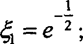
- ξ1
- der Wendepunktkoeffizient,
der die Intensität
eines Strahles am Wendepunkt seiner Intensitätsverteilung (Gaußverteilung)
bestimmt, der vom Zentrum (Maximum) dieser Verteilung um die Standardabweichung σ entfernt
ist:
- Imin_loc_abs
- das absolute Minimum zwischen den beiden lokalen Maxima;
- Idef_loc
- der lokale maximale
zulässige
Helligkeitswert eines Fehlers (defect):
- Imax_loc
- je nach Fehlerart der größere, kleinere oder mittlere von den beiden lokalen Maxima Imax_loc_left und Imax_loc_right;
- η0
- der Helligkeitsfaktor,
der eine allgemeine grundlegende Konstante für die Kantenerkennung darstellt:

- ξ2
- der Randpunktkoeffizient,
der die Intensität
eines Strahles am Rand seiner Intensitätsverteilung (Gaußverteilung)
bestimmt, der vom Zentrum (Maximum) dieser Verteilung um die zweifache Standardabweichung
2·σ entfernt
ist:
- I min_loc_left
- the brightness that the local minimum has left;
- I edge_loc_left
- the maximum brightness that an error may have on the left edge
- I max_loc_left
- the brightness having the left local maximum;
- I min_loc_right
- the brightness that the local minimum has on the right;
- I edge_loc_right
- the maximum brightness that an error may have on the right edge
- I max_loc_right
- the brightness having the right local maximum;
- ξ 1
- the inflection point coefficient, which determines the intensity of a ray at the inflection point of its intensity distribution (Gaussian distribution), which is distant from the center (maximum) of this distribution by the standard deviation σ:
- I min_loc_abs
- the absolute minimum between the two local maxima;
- I def_loc
- the local maximum permissible brightness value of a defect (defect):
- I max_loc
- depending on the type of error, the larger, smaller or medium of the two local maxima I max_loc_left and I max_loc_right ;
- η 0
- the brightness factor, which is a general basic constant for edge detection:
- ξ 2
- the boundary point coefficient, which determines the intensity of a ray at the edge of its intensity distribution (Gaussian distribution), which is distant from the center (maximum) of this distribution by twice the standard deviation 2 · σ:
Sofern alle oben genannten Bedingungen erfüllt sind, gehört die zu untersuchende Strecke zwischen den beiden gefundenen Kanten zu dem gesuchten Fehler.Provided all of the above conditions are met, that belongs to investigating distance between the two edges found to the searched errors.
Die genauen Positionen der gefundenen Kanten können dann nach unterschiedlichen bekannten Verfahren ermittelt werden.The exact positions of the found edges can then be different known methods are determined.
Auf diese Art und Weise muss das ganze Testbereich untersucht werden, wobei die Suchlinie in einer angegebenen Richtung, z.B. von oben nach unten, durch den Testbereich verschoben wird. Alle gefundene Strecken, die zu einem Fehler gehören, sollen dabei markiert werden. Damit werden sämtliche Fehler partiell markiert und mit Hilfe bekannter konventioneller Konturverfolgungsmethoden segmentiert und analysiert.On this way the whole test area needs to be examined wherein the search line is in a specified direction, e.g. from above down, is moved through the test area. All routes found, that belong to a mistake, should be marked. This will mark all errors partially and by known conventional contour tracking methods segmented and analyzed.
Gemäß Anspruch
2 kann ein Fehler erkannt werden kann, indem die minimale Helligkeit,
die er and der linken Kante Iedge_loc_left bzw.
rechten Kante Iedge_loc_right aufweisen
soll, sowie der lokale maximale zulässige Helligkeitswert eines
Fehlers Idef_loc folgendermaßen berechnet
werden:
Gemäß Anspruch 3 kann eine Beschädigung der Oberfläche (z.B. ein Riss) von einem anderem Objekttyp (z.B. eine Verschmutzung), der als Pseudo-Fehler bezeichnet werden kann, unterschieden werden und wird sicher als Fehler identifiziert. Dafür sollen zusätzliche lokale Merkmale wie das Auftreten eines Wulstes (bulge) und einer Rinne (hollow) für die Fehlererkennung benutzt werden, die aufgrund des Zerreißens und Entspannens eines Materials an jeder Kante eines Fehlers entstanden sind. In dem äußeren Bereich einer Kante schließt dabei das Grauwertprofil und der waagerechten Achse, die dem Niveau der lokalen Oberflächenhelligkeit Isurf_loc entspricht, einen Wulst, der eine Schnittflächen Abul aufweist. In dem inneren Bereichen schließt das Grauwertprofil und der waagerechten Achse, die dem Niveau der lokalen Oberflächenhelligkeit Isurf_loc entspricht, und der senkrechten Achse, die durch das absolute Minimum des Fehlers verläuft, eine Rinne, die eine Schnittfläche Aholl aufweist. Die Oberflächenhelligkeit Isurf_loc kann aus der lokalen Umgebung vor dem Wulst mit Hilfe konventioneller Methoden, z.B. Geradeapproximation, ermittelt werden.According to claim 3, damage to the surface (eg, a crack) of another type of object (eg, soiling), which may be called a pseudo-defect, can be discriminated and is surely identified as a defect. For this purpose, additional local features such as the appearance of a bead (bulge) and a groove (hollow) are used for the error detection, which have arisen due to the rupture and relaxation of a material at each edge of a fault. In the outer region of an edge, the gray value profile and the horizontal axis, which corresponds to the level of the local surface brightness I surf_loc , conclude a bead which has an intersection surface A bul . In the inner regions, the gray value profile and the horizontal axis corresponding to the local surface brightness level I surf_loc , and the vertical axis passing through the absolute minimum of the error, includes a groove having an intersection A holl . The surface brightness I surf_loc can be determined from the local environment in front of the bead using conventional methods, eg straight approximation.
Patentgemäß müssen diese
Flächen
miteinander verglichen werden. Sofern für einen ein lokaler Verhältniswert ![]()
![]()
Der minimale Fehlerschwellwert ϑdef kann je nach Fehlerart festgestellt und als Referenzwert verwendet werden.The minimum error threshold value θ def can be determined depending on the type of error and used as a reference value.
Gemäß Anspruch 4 kann eine Blase auf einer rauen Oberfläche als Fehler auf die gleiche Art und Weise wie eine Beschädigung erkannt werden kann, wobei vor dem oben beschriebenen Verfahren eine Invertierung der Parameter bei der Extremwertsuche oder eine Invertierung des gesamten Grauwertbildes durchgeführt werden muss.According to claim 4 may have a bubble on a rough surface as an error on the same Way like damage can be detected, taking before the method described above an inversion of the parameters in the extreme value search or a Inverting the entire gray scale image are performed got to.
Diese Fehlerform geht an die Oberflächenumformung beim Entstehen einer Blase zurück. Dabei wird die Oberfläche an der Blase heller und in der näheren Blasenumgebung dunkler, was auf eine Erhöhung und Vertiefung der Oberfläche zurückzuführen ist.These Error form goes to the surface deformation when a bubble comes up. In doing so, the surface becomes lighter at the bladder and closer Bubble environment darker, which is due to an increase and depression of the surface.
Gemäß Anspruch 5 kann das Grauwertprofil, das entlang einer Suchlinie gewonnen wird, die quer zu einer typischen Kante verläuft und evtl. mehrmals angelegt werden kann, sowohl aus einer einzelnen Pixelreihe als auch als Mittelwertkurve aus mehreren parallel zur Suchlinie liegenden benachbarten Pixelreihen gebildet werden. Die Anzahl der parallel zur Suchlinie liegenden benachbarten Pixelreihen, die jeweils zur Bildung des Grauwertprofils hinzugezogenen werden, kann z.B. als drei festgelegt werden. Diese wird eine sichere und genaue Ermittlung der maximalen Standardabweichung σ und damit der Fehlererkennung gewährleistet.According to claim 5, the gray value profile that is obtained along a search line which runs across a typical edge and possibly created several times can be, both from a single row of pixels as well as Mean value curve of several adjacent to the search line adjacent Pixel rows are formed. The number of parallel to the search line lying adjacent pixel rows, each for forming the Gray level profiles can be used, e.g. set as three become. This will be a safe and accurate determination of the maximum Standard deviation σ and thus ensuring error detection.
Gemäß Anspruch 6 kann der typische Wert für die maximale Standardabweichung σ an der Kante eines Fehlers, die unter konkreten Aufnahmebedingungen ganz spezifisch aussehen kann, nach Erfahrungswerten festgelegt werden.According to claim 6 can be the typical value for the maximum standard deviation σ the edge of a mistake under specific shooting conditions can look very specific, based on experience become.
Das beschriebene adaptive Verfahren erlaubt die Erkennung eines Fehlers, dessem Helligkeit sich von der Oberflächenhelligkeit beispielsweise geringfügig unterscheidet, indem gemäß Anspruch 7 für die Berechnung der minimalen Helligkeit, die ein Fehlerkandidat and der linken Kante Iedge_loc_left bzw. an der rechten Kante Iedge_loc_right aufweisen soll, anstatt der Konstante ξ1 für das Wendepunktkoeffizient ein Kantenfaktor ζ verwendet wird, dessen Größe im Bereich [0 – 1] liegt und nach Erfahrungswerten festgestellt werden kann.The described adaptive method allows the detection of an error whose brightness differs slightly from the surface brightness, for example, according to claim 7 for the calculation of the minimum brightness which an error candidate on the left edge I edge_loc_left or on the right edge I edge_loc_right should have , instead of the constant ξ 1 for the turning point coefficient, an edge factor ζ is used, whose size is in the range [0 - 1] and can be determined based on experience.
Gemäß Anspruch 8 kann ein solcher Fehler ebenso erkannt werden, indem für die Berechnung der minimalen Helligkeit, die ein Fehler and der linken Kante Iedge_loc_left bzw. an der rechten Kante Iedge_loc_right aufweisen soll, sowie des lokalen maximalen zulässigen Helligkeitswertes eines Fehlers Idef_loc anstatt des Randpunktkoeffizientes ξ2 ein Hintergrundfaktor ξ verwendet wird, dessen Größe im Bereich [0 – 1] liegt und nach Erfahrungswerten festgestellt werden kann.According to claim 8 such an error can also be detected by using for the calculation of the minimum brightness, which should have an error on the left edge I edge_loc_left or on the right edge I edge_loc_right , as well as the local maximum allowable brightness value of an error I def_loc instead of the boundary point coefficient ξ 2 a background factor ξ is used whose size is in the range [0 - 1] and can be determined according to empirical values.
Gemäß Anspruch 9 kann ein solcher Fehler ebenso erkannt werden, indem für die Berechnung des lokalen maximalen zulässigen Helligkeitswertes eines Fehlers Idef_loc anstatt der Konstante η0 für die Kantenerkennung ein Fehlerfaktor η verwendet wird, dessen Größe im Bereich [0 – 1] liegt und nach Erfahrungswerten festgestellt werden kann.According to claim 9, such an error can also be detected by using an error factor η whose magnitude is in the range [0-1] and after, instead of the constant η 0 for edge detection, for calculating the local maximum permissible brightness value of an error I def_loc Experience can be determined.
Gemäß Anspruch 10 soll nur jede einzelne zu untersuchende Kurve wie beispielsweise einen Grauwertverlauf aber nicht das Bild selbst geglättet werden. Damit werden die zu untersuchenden Kurven von originalen Bildwerten gebildet und nicht schon im Voraus verfälscht.According to claim 10 should only every single curve to be examined such as a gray level gradient but not the image itself will be smoothed. This turns the curves to be examined from original image values formed and not falsified in advance.
Gemäß Anspruch 11 soll eine morphologische Filterung für die Glättung der zu untersuchenden Kurven verwendet werden. Diese verursacht keine Verfälschung der zu untersuchenden Kurven, wie beim Einsatz konventioneller Filterungsmethoden, und erlaubt damit eine fehlerfreie Kurvendiskussion.According to claim 11 is a morphological filtering for the smoothing of the examined Curves are used. This does not cause adulteration the curves to be examined, as in the case of conventional filtering methods, and thus allows a faultless curve discussion.
Durch das hier genannte Verfahren zur adaptiven Fehlererkennung kann auf die Erkennung eines Fehlers auf einer inhomogenen Oberfläche anhand der Strukturanalyse-Methoden sowie der traditionellen kantenbasierten Segmentierungsmethoden verzichtet werden.By the method mentioned here for adaptive error detection can detecting an error on an inhomogeneous surface the structural analysis methods and traditional edge-based segmentation methods be waived.
Die
Einzelheiten der Erfindung werden in den nachfolgenden Ausführungsbeispielen
anhand der
Als
Beispiel kann angenommen werden, dass ein dunkler Fehler
Die
Standardabweichung σ0 des Grauwertprofils (
Um alle Merkmale zu definieren, die für eine adaptive Fehlererkennung benötigt werden, soll zuerst ein Verfahren zur adaptiven Kantensuche beschrieben werden, das der Fehlererkennung zugrunde liegt.Around Define all features necessary for adaptive error detection needed will first describe an adaptive edge search method that underlies error detection.
Wie bereits oben begründet wurde, weist das Grauwertprofil ein Gaußsches bzw. ein aus mehreren Gaußverteilungen resultierendes Profil auf. Das bedeutet, dass diese Kurven eine Normalverteilung nach Gauß und damit eine exponentielle Funktion darstellen und somit bestimmte Verhältnisse zwischen charakteristischen Punkten besitzen.As already justified above has, the gray value profile has a Gaussian or one of several Gaussian distributions resulting profile. That means that these curves are one Normal distribution according to Gauss and thus represent an exponential function and thus certain conditions between characteristic points.
Das
Grauwertprofil kann als Gaußsches
Profil folgendermaßen
berechnet werden: ![]()
- I(x)
- aktuelle Helligkeit, die der zu untersuchende Punkt auf der Kante aufweist, der sich in der Entfernung x vom Profilmaximum befindet;
- Isurf
- Oberflächenhelligkeit, die auf dem Profilmaximum erstmalig und sicher auftritt;
- x
- die Entfernung des zu untersuchenden Punktes von dem Punkt, der das Profilmaximum aufweist.
- I (x)
- actual brightness of the point to be examined on the edge located at the distance x from the profile maximum;
- I surf
- Surface brightness which occurs for the first time and safely on the profile maximum;
- x
- the distance of the point to be examined from the point having the profile maximum.
Die
wichtigsten Punkte auf dem Grauwertprofil für das vorliegenden Verfahren
sind Stellen, die eine Entfernung von dem Maximum des Profils haben,
die der einfachen und der zweifachen Standardabweichung des Gaußschen Profils
entsprechen (
Die
einfache Standardabweichung σ ausgehend
vom Maximum des Profils zeigt auf einen Punkt, an dem das Grauwertprofil
einen Wendepunkt Iturn (turn point) besitzt.
Hier kann sich damit theoretisch eine Kante
- Isurf
- die Oberflächenhelligkeit;
- ξ1
- der Wendepunktkoeffizient:

- I surf
- the surface brightness;
- ξ 1
- the turning point coefficient:
Die
zweifache Standardabweichung 2·σ ausgehend
vom Maximum des Profils zeigt auf einen Punkt, an dem das Grauwertprofil
die Intensität
des Strahlrands hat und sich damit der Hintergrund
Der
Abstand zwischen den beiden Punkten, welche die Werte Iturn und
Ibgrd aufweisen, entspricht ebenso der Standardabweichung σ und ist
vom jeweiligen Grauwertprofil (![]()
![]()
Damit
stellt der Helligkeitsfaktor η0 ein minimales Verhältnis zwischen den Helligkeiten
der frühest möglichen
Kantenposition
Aus
dem Grauwertprofil (
Einer
der wichtigsten Parameter des Grauwertprofils ist die Teststrecke,
mit der das Grauwertprofil abgesucht werden soll, um die Position
der zu untersuchenden Kante
Die
Länge dieser
Teststrecke L0 darf dabei nicht kleiner
als der Abstand zwischen dem Wendepunkt Iturn und
dem Randpunkt (Hintergrundhelligkeit Ibgrd)
sein, was genau der Standardabweichung σ des Grauwertprofils entspricht.
Gleichzeitig darf die Teststrecke L0 die
doppelte Größe der Standardabweichung σ nicht überschreiten.
Sonst wird die Teststrecke größer als
der gesamte Übergangsbereich
Dies
bedeutet, dass eine Kante ![]()
- Imax
- die lokale maximale Helligkeit innerhalb der Teststrecke L0;
- Imin
- die lokale minimale Helligkeit innerhalb der Teststrecke L0;
- ΔI
- die lokale Helligkeitssteigung innerhalb der Teststrecke L0;
- η
- der lokale Helligkeitsfaktor innerhalb der Teststrecke L0.
- I max
- the local maximum brightness within the test distance L 0 ;
- I min
- the local minimum brightness within the test distance L 0 ;
- .DELTA.I
- the local brightness gradient within the test track L 0 ;
- η
- the local brightness factor within the test distance L 0 .
Zur
Bestimmung der Parameter I0 und ΔI0 werden folgende Grenzfälle betrachtet. Wenn der Endpunkt der
Teststrecke L0 bereits die Oberfläche
Die
lokale minimale Helligkeit Imin entspricht
dabei noch nicht der Oberflächenhelligkeit
(Imin < Isurf) aber nicht mehr der Hintergrundhelligkeit
(Imin > Ibgrd). Sie weist nun auf einen Übergangsbereich
Befindet
sich der Endpunkt der Teststrecke L0 bereits
in einer Position, die der Helligkeit I0 entspricht, und
der Startpunkt noch auf dem Hintergrund
Damit
kann eine Kante
Nun
können
die Bedingungen für
die Erkennung eines Fehlers
Ein
Grauwertprofil, das entlang der Suchlinie
Diese
Bedingung für
eine existierende Kante soll sowohl an der linken als auch an der
rechten Seite eines Fehlers
Erfindungsgemäß wird dabei
das Grauwertprofil untersucht, das quer zu einer Kante verläuft. Die
lokale minimale Helligkeit Imin_loc, die
möglicherweise
noch nicht das absolute Minimum des zu suchenden Fehlers
- Imin_loc_left
- die Helligkeit, die das lokale Minimum links aufweist;
- Iedge_loc_left
- die maximale Helligkeit,
die ein Fehler and der linken Kante aufweisen darf:
- Imax_loc_left
- die Helligkeit, die das linke lokale Maximum aufweist;
- Imin_loc_right
- die Helligkeit, die das lokale Minimum rechts aufweist;
- Iedge_loc_right
- die maximale Helligkeit,
die ein Fehler and der rechten Kante aufweisen darf
- Imax_loc_right
- die Helligkeit, die das rechte lokale Maximum aufweist;
- ξ1
- der Wendepunktkoeffizient, der die Intensität eines Strahles am Wendepunkt seiner Intensitätsverteilung (Gaußverteilung) bestimmt, der vom Zentrum (Maximum) dieser Verteilung um die Standardabweichung σ0 entfernt ist.
- I min_loc_left
- the brightness that the local minimum has left;
- I edge_loc_left
- the maximum brightness that an error can have on the left edge:
- I max_loc_left
- the brightness having the left local maximum;
- I min_loc_right
- the brightness that the local minimum has on the right;
- I edge_loc_right
- the maximum brightness that an error may have on the right edge
- I max_loc_right
- the brightness having the right local maximum;
- ξ 1
- the inflection point coefficient, which determines the intensity of a ray at the inflection point of its intensity distribution (Gaussian distribution), which is distant from the center (maximum) of this distribution by the standard deviation σ 0 .
Die weitere Untersuchung des Grauwertprofils zwischen den beiden erkannten Kanten eines möglichen Fehlers besteht darin, dass das dort ermittelte Helligkeitsminimum Imin_loc_abs, welches das absolute Minimum zwischen den beiden lokalen Maxima darstellt, mit dem lokalen maximalen zulässigen Helligkeitswert eines Fehlers Idef_loc (defect) verglichen werden muss.The further investigation of the gray value profile between the two recognized edges of a possible error consists in comparing the minimum brightness I min_loc_abs determined there, which represents the absolute minimum between the two local maxima, with the local maximum permissible brightness value of an error I def_loc (defect) got to.
Nach
(13) kann der Helligkeitswert Idef_loc folgendermaßen definiert
werden:
- Imax_loc
- der Helligkeitswert, der je nach Fehlerart der größere, kleinere oder mittlere von den beiden lokalen Maxima Imax_loc_left und Imax_loc_right entspricht.
- I max_loc
- the brightness value which, depending on the type of error, corresponds to the larger, smaller or medium of the two local maxima I max_loc_left and I max_loc_right .
Sofern
gilt:
Die exakten Positionen der Kanten können nach unterschiedlichen bekannten Verfahren (Methoden der digitalen Bildsignalverarbeitung/Piero Zamperoni. – Braunschweig/Wiesbaden: Friedr. Vieweg & Sohn, 1989; Digitale Bildverarbeitung/Bernd Jähne. – 4. Aufl. – Berlin, Heidelberg, etc.: Springer, 1997), u.a. mit Subpixel-Genauigkeit (A Comparison of Algorithms for Sub-pixel Peak Detection/D. K. Naidu, R. B. Fisher. Department of Artifical Intelligence, – University of Edinburgh, Scotland, U.K., DAI Research Paper No. 553, Oktober 17, 1991) ermittelt werden.The exact positions of the edges can according to different known methods (methods of digital Image signal processing / Piero Zamperoni. - Brunswick / Wiesbaden: Friedr. Vieweg & Son, 1989; Digital Image Processing / Bernd Jähne. - 4th edition - Berlin, Heidelberg, etc .: Springer, 1997), et al. with subpixel accuracy (A Comparison of Algorithms for Sub-pixel Peak Detection / D. K. Naidu, R. B. Fisher. Department of Artifical Intelligence, - University of Edinburgh, Scotland, U.K., DAI Research Paper no. 553, October 17, 1991) become.
Auf diese Art und Weise muss der gesamte Testbereich 4 untersucht werden. Alle gefundene Strecken, die zu einem Fehler gehören, sollen dabei markiert werden. Damit werden sämtliche Fehler partiell markiert und mit Hilfe bekannter konventioneller Konturverfolgungsmethoden (Handbuch der Operatoren für die Bildverarbeitung/Reinhard Klette, Piero Zamperoni. -Braunschweig/Wiesbaden: Friedr. Vieweg & Sohn, 1995) segmentiert und analisiert.On this way, the entire test area 4 must be examined. All found routes that belong to an error should be marked become. This will be all Errors partially marked and using known conventional Contour Tracing Methods (Handbook of Operators for Image Processing / Reinhard Burdock, Piero Zamperoni. -Braunschweig / Wiesbaden: Friedr. Vieweg & Sohn, 1995) and analized.
Die
Schwellwerte Imax_loc_left, Imax_loc_right und
Idef_loc, die für die Detektierung des Fehlers
Nach
(4) und (24)–(26):
Falls
eine Beschädigung
der Oberfläche
(z.B. ein Riss
Das
Grauwertprofil schließt
in dem äußeren Bereich
einer Kante mit der waagerechten Achse
Patentgemäß müssen diesen
Flächen
mit einander verglichen werden. Sofern ein lokaler Verhältniswert ![]()
![]()
Der minimale Fehlerschwellwert ϑdef kann je nach Fehlerart nach Erfahrungswerten festgestellt und im weiteren als Referenzwert verwendet werden.Depending on the type of error, the minimum error threshold value θ def can be determined on the basis of empirical values and used subsequently as the reference value.
Eine
Blase
Damit lässt das oben beschriebene adaptive Verfahren einen auf einer inhomogenen Oberfläche vorhandenen Fehler explizit erkennen.In order to lets that go The adaptive method described above is one on an inhomogeneous one surface Explicitly recognize existing errors.
Literaturliterature
- 1. Frei konfigurierbare regionalbasierte Farbtexturanalyse zur automatischen Auswertung von Bild-Stichproben/A. Burmeister. – Arbeit zur Erlangung des Grades „Doktor- Ingenieur" – Der Technischen Fakultät der Universität Erlangen-Nürnberg: Erlangen, 1999.1. Freely configurable regional based color texture analysis for automatic evaluation of image samples / A. Burmeister. - Job to obtain the degree "Doctor-Ingenieur" - The Technical Faculty of the University Erlangen-Nürnberg: Erlangen, 1999.
-
2. Patent
DE 29521937 U1 DE 29521937 U1 -
3. Patent
DE 19549216 A1 DE 19549216 A1 - 4. Automatische Extraktion von Festigkeits und optisch relevanten Merkmalen aus Farbbildern von Schnittholzflächen. – DGfH-Nr. F-98/01, Projektleitung: Prof. Dr.-Ing. Habil. S. Fuchs, Universität Dresden, Fakultät Informatik, Institut für künstliche Intelligenz, 2002.4. Automatic extraction of strength and visually relevant Characteristics of color images of sawn timber surfaces. - DGfH no. F-98/01, project leader: Prof. Dr.-Ing. Habil, S. Fuchs, University of Dresden, Faculty of Computer Science, Institute for artificial Intelligence, 2002.
- 5. Digitale Bildverarbeitung/Bernd Jähne. – 4. Aufl. – Berlin, Hedelberg, etc.: Springer, 1997.5. Digital Image Processing / Bernd Jähne. - 4th edition - Berlin, Hedelberg, etc .: Springer, 1997.
-
6. Patent
DE 19902401 C2 DE 19902401 C2 -
7. Patent
DE 4131778 C2 DE 4131778 C2 -
8. Patent
EP 0750272 B1 EP 0750272 B1 -
9. Patent
EP 0807297 B1 EP 0807297 B1 - 10. Patent US 203/0063802 A1.10. Patent US 203/0063802 A1.
- 11. Industrielle Bildverarbeitung/Christian Demant, Bernd Streicher-Abel, Peter Waszkewitz. – Berlin; Heidelberg: Springer, 1998.11. Industrial Image Processing / Christian Demant, Bernd Streicher-Abel, Peter Waszkewitz. - Berlin; Heidelberg: Springer, 1998.
-
12. Patent
DE 4435796 C1 DE 4435796 C1 - 13. Technische Optik: Grundlagen und Anwendungen/Gottfried Schröder. – 7. Aufl. – Würzburg: Vogel, 1990 (Kamprath-Reihe), S. 88.13. Technical Optics: Fundamentals and Applications / Gottfried Schröder. - 7th edition - Würzburg: Vogel, 1990 (Kamprath Series), p. 88.
- 14. A Comparison of Algorithms for Sub-pixel Peak Detection/D. K. Naidu, R. B. Fisher. Department of Artifical Intelligence, University of Edinburgh, Scotland, U.K., DAI Research Paper No. 553, Oktober 17, 1991.14. A Comparison of Algorithms for Sub-pixel Peak Detection / D. K. Naidu, R. B. Fisher. Department of Artifical Intelligence, University of Edinburgh, Scotland, U.K., DAI Research Paper no. 553, October 17, 1991.
- 15. Methoden der digitalen Bildsignalverarbeitung/Piero Zamperoni. – Braunschweig/ Wiesbaden: Friedr. Vieweg & Sohn, 1989.15. Methods of digital image signal processing / Piero Zamperoni. - Brunswick / Wiesbaden: Friedr. Vieweg & Son, 1989th
- 16. Handbuch der Operatoren für die Bildverarbeitung/Reinhard Klette, Piero Zamperoni. – Braunschweig/Wiesbaden: Friedr. Vieweg & Sohn, 1995.16. Manual of Operators for Image Processing / Reinhard Burdock, Piero Zamperoni. - Brunswick / Wiesbaden: Friedr. Vieweg & Son, 1995th
- 11
- Hintergrundbackground
- 22
- Oberflächesurface
- 33
- Kante zwischen dem Hintergrund und der Oberfächeedge between the background and the surface
- 44
- Testbereich auf der Oberflächetest area on the surface
- 55
- Suchlinie im Testbereich auf der Oberflächesearch line in the test area on the surface
- 66
- Fehler auf der Oberflächeerror on the surface
- 77
- Suchlinie quer zur Kante zwischen dem Hintergrund und der Oberflächesearch line across the edge between the background and the surface
- 88th
- Übergangsbereich zwischen dem Hintergrund und der OberflächeTransition area between the background and the surface
- 99
- Wulst an einem Fehlerbead at a mistake
- 1010
- Rinne an einem Fehlergutter at a mistake
- 1111
- Waagerechte Achse, die dem Niveau der lokalen Oberflächenhelligkeit entsprichthorizontal Axis that corresponds to the level of local surface brightness
- 1212
- Senkrechte Achse, die durch das absolute Minimum (Riss) bzw. Maximum (Blase) des Fehlers verläuftvertical Axis defined by the absolute minimum (crack) or maximum (bubble) the error proceeds
- 1313
- Grauwertprofil quer zu einem RissGray scale profile across to a crack
- 1414
- Grauwertprofil quer zu einer BlaseGray scale profile across to a bubble
Claims (11)
Priority Applications (2)
| Application Number | Priority Date | Filing Date | Title |
|---|---|---|---|
| DE10326033A DE10326033B4 (en) | 2003-06-10 | 2003-06-10 | Method for adaptive error detection on an inhomogeneous surface |
| EP04013430A EP1486918A3 (en) | 2003-06-10 | 2004-06-08 | Method for adaptive flawdetection on an inhomogeneous surface |
Applications Claiming Priority (1)
| Application Number | Priority Date | Filing Date | Title |
|---|---|---|---|
| DE10326033A DE10326033B4 (en) | 2003-06-10 | 2003-06-10 | Method for adaptive error detection on an inhomogeneous surface |
Publications (2)
| Publication Number | Publication Date |
|---|---|
| DE10326033A1 DE10326033A1 (en) | 2005-01-13 |
| DE10326033B4 true DE10326033B4 (en) | 2005-12-22 |
Family
ID=33185727
Family Applications (1)
| Application Number | Title | Priority Date | Filing Date |
|---|---|---|---|
| DE10326033A Withdrawn - After Issue DE10326033B4 (en) | 2003-06-10 | 2003-06-10 | Method for adaptive error detection on an inhomogeneous surface |
Country Status (2)
| Country | Link |
|---|---|
| EP (1) | EP1486918A3 (en) |
| DE (1) | DE10326033B4 (en) |
Families Citing this family (10)
| Publication number | Priority date | Publication date | Assignee | Title |
|---|---|---|---|---|
| JPWO2006112466A1 (en) * | 2005-04-19 | 2008-12-11 | 松下電器産業株式会社 | Mirror surface foreign matter inspection method |
| US8013841B2 (en) * | 2006-06-16 | 2011-09-06 | Em Microelectronic-Marin S.A. | Enhanced lift detection technique for a laser illuminated optical mouse sensor |
| CN105719259B (en) * | 2016-02-19 | 2018-11-13 | 上海理工大学 | Pavement crack image detecting method |
| CN106274979B (en) * | 2016-08-30 | 2018-06-22 | 大连民族大学 | Rail wear automatic detection device |
| CN110779928B (en) * | 2019-11-19 | 2022-07-26 | 汪科道 | Defect detection device and method |
| CN111127415B (en) * | 2019-12-19 | 2023-07-25 | 信利(仁寿)高端显示科技有限公司 | Mura quantification method based on excimer laser annealing |
| CN112037126B (en) * | 2020-07-02 | 2022-11-22 | 电子科技大学 | Image synthesis method for detecting object surface crack defects based on laser scanning method |
| CN113362288B (en) * | 2021-05-24 | 2024-03-08 | 深圳明锐理想科技股份有限公司 | Golden finger scratch detection method and device and electronic equipment |
| CN115797342B (en) * | 2023-02-06 | 2023-04-21 | 深圳市鑫旭飞科技有限公司 | Industrial control capacitive touch LCD display assembly defect detection method |
| CN117593302A (en) * | 2024-01-18 | 2024-02-23 | 新西旺智能科技(深圳)有限公司 | Defective part tracing method and system |
Citations (8)
| Publication number | Priority date | Publication date | Assignee | Title |
|---|---|---|---|---|
| DE4435796C1 (en) * | 1994-10-06 | 1995-12-07 | Siemens Ag | Automatic digital detection of edges and diameter in pref. X=ray images |
| DE4131778C2 (en) * | 1991-03-28 | 1996-10-10 | Samsung Electronics Co Ltd | Method and device for edge detection for an image processing system |
| DE19549216A1 (en) * | 1995-12-30 | 1997-07-03 | Fraunhofer Ges Forschung | Camera pictures evaluation method |
| DE29521937U1 (en) * | 1995-05-10 | 1998-12-03 | Mahlo Gmbh & Co Kg | Test system for moving material |
| EP0807297B1 (en) * | 1995-01-31 | 1999-09-29 | United Parcel Service Of America, Inc. | Method and apparatus for separating foreground from background in images containing text |
| EP0750272B1 (en) * | 1995-06-23 | 2000-05-10 | Kabushiki Kaisha Toshiba | Image binarization apparatus and method |
| DE19902401C2 (en) * | 1999-01-22 | 2001-02-01 | Wohlenberg Schneidesysteme Gmb | Method and device for determining the geometry of sheet-like material or stacks thereof |
| US20030063802A1 (en) * | 2001-07-26 | 2003-04-03 | Yulin Li | Image processing method, apparatus and system |
Family Cites Families (4)
| Publication number | Priority date | Publication date | Assignee | Title |
|---|---|---|---|---|
| US4859850A (en) * | 1987-01-12 | 1989-08-22 | Fuji Photo Film Co., Ltd. | Irradiation field recognizing method, and method of adjusting image processing conditions using the same |
| AU627658B2 (en) * | 1990-06-13 | 1992-08-27 | Aluminium Company Of America | Video inspection system |
| US5440648A (en) * | 1991-11-19 | 1995-08-08 | Dalsa, Inc. | High speed defect detection apparatus having defect detection circuits mounted in the camera housing |
| JP2002189164A (en) * | 2000-12-21 | 2002-07-05 | Minolta Co Ltd | Optical system controller, optical system control method, and recording medium |
-
2003
- 2003-06-10 DE DE10326033A patent/DE10326033B4/en not_active Withdrawn - After Issue
-
2004
- 2004-06-08 EP EP04013430A patent/EP1486918A3/en not_active Withdrawn
Patent Citations (8)
| Publication number | Priority date | Publication date | Assignee | Title |
|---|---|---|---|---|
| DE4131778C2 (en) * | 1991-03-28 | 1996-10-10 | Samsung Electronics Co Ltd | Method and device for edge detection for an image processing system |
| DE4435796C1 (en) * | 1994-10-06 | 1995-12-07 | Siemens Ag | Automatic digital detection of edges and diameter in pref. X=ray images |
| EP0807297B1 (en) * | 1995-01-31 | 1999-09-29 | United Parcel Service Of America, Inc. | Method and apparatus for separating foreground from background in images containing text |
| DE29521937U1 (en) * | 1995-05-10 | 1998-12-03 | Mahlo Gmbh & Co Kg | Test system for moving material |
| EP0750272B1 (en) * | 1995-06-23 | 2000-05-10 | Kabushiki Kaisha Toshiba | Image binarization apparatus and method |
| DE19549216A1 (en) * | 1995-12-30 | 1997-07-03 | Fraunhofer Ges Forschung | Camera pictures evaluation method |
| DE19902401C2 (en) * | 1999-01-22 | 2001-02-01 | Wohlenberg Schneidesysteme Gmb | Method and device for determining the geometry of sheet-like material or stacks thereof |
| US20030063802A1 (en) * | 2001-07-26 | 2003-04-03 | Yulin Li | Image processing method, apparatus and system |
Also Published As
| Publication number | Publication date |
|---|---|
| EP1486918A3 (en) | 2006-05-31 |
| EP1486918A2 (en) | 2004-12-15 |
| DE10326033A1 (en) | 2005-01-13 |
Similar Documents
| Publication | Publication Date | Title |
|---|---|---|
| DE10326035B4 (en) | Method for adaptive error detection on a structured surface | |
| DE102011081668B4 (en) | Apparatus and method for determining the shape of the end of a weld | |
| DE3937950C2 (en) | ||
| DE19521346C2 (en) | Image examination / recognition method, method used therein for generating reference data and devices therefor | |
| DE69818438T2 (en) | METHOD FOR CONTROLLING THE SURFACE OF A CONTINUOUS MATERIAL RAIL WITH IMAGE SEGMENTATION FOR DETERMINING DEFECTIVE AREAS | |
| DE10326033B4 (en) | Method for adaptive error detection on an inhomogeneous surface | |
| WO2019166361A1 (en) | Method for splitting one or more images of a sample into image data split according to dyes, computer program product, computer-readable medium storing the computer program product and system for splitting one or more images of a sample into image data split according to dyes | |
| DE102013005489B4 (en) | Method and device for the automatic detection of defects in limp bodies | |
| DE69821225T2 (en) | METHOD FOR CONTROLLING THE SURFACE OF A CONTINUOUS MATERIAL RAIL WITH PRE-CLASSIFICATION OF DETERMINED IRREGULARITIES | |
| DE102005025220B4 (en) | Apparatus, method and program for removing pores | |
| DE102004049482A1 (en) | Device for monitoring moving objects | |
| DE10326032B4 (en) | Method for self-testing an image processing system | |
| EP3655920B1 (en) | Method and device for analysing image sections for a correspondence calculation | |
| DE112018000224B4 (en) | Method and device for determining a position of a slit in a sample to be processed | |
| DE10326031B4 (en) | Method for adaptive edge detection | |
| EP3142068B1 (en) | Method for three-dimensional recording of objects | |
| DE102017129168A1 (en) | Spectrum classification method, classification method and receiving device | |
| DE102021118209A1 (en) | System for extracting an outline of a static object and method therefor | |
| EP3214602A1 (en) | Method for three-dimensional recording of objects | |
| EP3367333B1 (en) | Method for characterising an object | |
| EP2463175B1 (en) | Method for locating surface defects | |
| AT511399B1 (en) | METHOD FOR THE AUTOMATED CLASSIFICATION OF INCLUSIONS | |
| DE10301634B4 (en) | Local-adaptive object recognition for digital image material | |
| DE102022208384A1 (en) | Method for determining a quality condition of a test object | |
| EP4285319A1 (en) | Generation of training data for two-dimensional scans of a ground radar system |
Legal Events
| Date | Code | Title | Description |
|---|---|---|---|
| OP8 | Request for examination as to paragraph 44 patent law | ||
| 8122 | Nonbinding interest in granting licences declared | ||
| 8120 | Willingness to grant licences paragraph 23 | ||
| 8127 | New person/name/address of the applicant |
Owner name: HEMA ELECTRONIC GMBH, 73431 AALEN, DE |
|
| 8364 | No opposition during term of opposition | ||
| R081 | Change of applicant/patentee |
Owner name: LOUBAN, ROMAN, DR.-ING., DE Free format text: FORMER OWNER: HEMA ELECTRONIC GMBH, 73431 AALEN, DE Effective date: 20120827 Owner name: ROMAN LOUBAN, DE Free format text: FORMER OWNER: HEMA ELECTRONIC GMBH, 73431 AALEN, DE Effective date: 20120827 |
|
| R120 | Application withdrawn or ip right abandoned |