EP1505286A2 - Vehicle-drive control system and method and program therefor - Google Patents
Vehicle-drive control system and method and program therefor Download PDFInfo
- Publication number
- EP1505286A2 EP1505286A2 EP04013173A EP04013173A EP1505286A2 EP 1505286 A2 EP1505286 A2 EP 1505286A2 EP 04013173 A EP04013173 A EP 04013173A EP 04013173 A EP04013173 A EP 04013173A EP 1505286 A2 EP1505286 A2 EP 1505286A2
- Authority
- EP
- European Patent Office
- Prior art keywords
- engine
- target
- speed
- generator
- drive
- Prior art date
- Legal status (The legal status is an assumption and is not a legal conclusion. Google has not performed a legal analysis and makes no representation as to the accuracy of the status listed.)
- Granted
Links
- 238000000034 method Methods 0.000 title claims description 262
- 230000009467 reduction Effects 0.000 claims abstract description 79
- 238000004364 calculation method Methods 0.000 claims description 115
- 230000008859 change Effects 0.000 claims description 30
- 238000004590 computer program Methods 0.000 claims description 5
- 239000003921 oil Substances 0.000 abstract description 9
- 238000001816 cooling Methods 0.000 abstract description 8
- 230000001050 lubricating effect Effects 0.000 abstract description 8
- 230000008569 process Effects 0.000 description 185
- 238000010586 diagram Methods 0.000 description 69
- 238000011946 reduction process Methods 0.000 description 23
- 239000000446 fuel Substances 0.000 description 15
- 238000006243 chemical reaction Methods 0.000 description 11
- 230000003247 decreasing effect Effects 0.000 description 10
- 238000001514 detection method Methods 0.000 description 10
- 238000002347 injection Methods 0.000 description 10
- 239000007924 injection Substances 0.000 description 10
- 230000005540 biological transmission Effects 0.000 description 9
- 238000002485 combustion reaction Methods 0.000 description 7
- 230000035939 shock Effects 0.000 description 7
- 230000001133 acceleration Effects 0.000 description 6
- 238000007906 compression Methods 0.000 description 6
- 230000007423 decrease Effects 0.000 description 6
- 101100134058 Caenorhabditis elegans nth-1 gene Proteins 0.000 description 5
- 230000006870 function Effects 0.000 description 3
- 230000007812 deficiency Effects 0.000 description 2
- 230000003111 delayed effect Effects 0.000 description 2
- 230000000994 depressogenic effect Effects 0.000 description 2
- 239000000203 mixture Substances 0.000 description 2
- 230000008929 regeneration Effects 0.000 description 2
- 238000011069 regeneration method Methods 0.000 description 2
- 230000002441 reversible effect Effects 0.000 description 2
- 239000003990 capacitor Substances 0.000 description 1
- 239000000969 carrier Substances 0.000 description 1
- 230000006835 compression Effects 0.000 description 1
- 230000005611 electricity Effects 0.000 description 1
- 238000009499 grossing Methods 0.000 description 1
- 238000005259 measurement Methods 0.000 description 1
- 230000007246 mechanism Effects 0.000 description 1
- 238000012986 modification Methods 0.000 description 1
- 230000004048 modification Effects 0.000 description 1
- 230000001360 synchronised effect Effects 0.000 description 1
- 238000011144 upstream manufacturing Methods 0.000 description 1
Images


Classifications
-
- F—MECHANICAL ENGINEERING; LIGHTING; HEATING; WEAPONS; BLASTING
- F02—COMBUSTION ENGINES; HOT-GAS OR COMBUSTION-PRODUCT ENGINE PLANTS
- F02D—CONTROLLING COMBUSTION ENGINES
- F02D35/00—Controlling engines, dependent on conditions exterior or interior to engines, not otherwise provided for
- F02D35/02—Controlling engines, dependent on conditions exterior or interior to engines, not otherwise provided for on interior conditions
-
- B—PERFORMING OPERATIONS; TRANSPORTING
- B60—VEHICLES IN GENERAL
- B60L—PROPULSION OF ELECTRICALLY-PROPELLED VEHICLES; SUPPLYING ELECTRIC POWER FOR AUXILIARY EQUIPMENT OF ELECTRICALLY-PROPELLED VEHICLES; ELECTRODYNAMIC BRAKE SYSTEMS FOR VEHICLES IN GENERAL; MAGNETIC SUSPENSION OR LEVITATION FOR VEHICLES; MONITORING OPERATING VARIABLES OF ELECTRICALLY-PROPELLED VEHICLES; ELECTRIC SAFETY DEVICES FOR ELECTRICALLY-PROPELLED VEHICLES
- B60L58/00—Methods or circuit arrangements for monitoring or controlling batteries or fuel cells, specially adapted for electric vehicles
- B60L58/10—Methods or circuit arrangements for monitoring or controlling batteries or fuel cells, specially adapted for electric vehicles for monitoring or controlling batteries
- B60L58/12—Methods or circuit arrangements for monitoring or controlling batteries or fuel cells, specially adapted for electric vehicles for monitoring or controlling batteries responding to state of charge [SoC]
-
- B—PERFORMING OPERATIONS; TRANSPORTING
- B60—VEHICLES IN GENERAL
- B60K—ARRANGEMENT OR MOUNTING OF PROPULSION UNITS OR OF TRANSMISSIONS IN VEHICLES; ARRANGEMENT OR MOUNTING OF PLURAL DIVERSE PRIME-MOVERS IN VEHICLES; AUXILIARY DRIVES FOR VEHICLES; INSTRUMENTATION OR DASHBOARDS FOR VEHICLES; ARRANGEMENTS IN CONNECTION WITH COOLING, AIR INTAKE, GAS EXHAUST OR FUEL SUPPLY OF PROPULSION UNITS IN VEHICLES
- B60K6/00—Arrangement or mounting of plural diverse prime-movers for mutual or common propulsion, e.g. hybrid propulsion systems comprising electric motors and internal combustion engines ; Control systems therefor, i.e. systems controlling two or more prime movers, or controlling one of these prime movers and any of the transmission, drive or drive units Informative references: mechanical gearings with secondary electric drive F16H3/72; arrangements for handling mechanical energy structurally associated with the dynamo-electric machine H02K7/00; machines comprising structurally interrelated motor and generator parts H02K51/00; dynamo-electric machines not otherwise provided for in H02K see H02K99/00
- B60K6/20—Arrangement or mounting of plural diverse prime-movers for mutual or common propulsion, e.g. hybrid propulsion systems comprising electric motors and internal combustion engines ; Control systems therefor, i.e. systems controlling two or more prime movers, or controlling one of these prime movers and any of the transmission, drive or drive units Informative references: mechanical gearings with secondary electric drive F16H3/72; arrangements for handling mechanical energy structurally associated with the dynamo-electric machine H02K7/00; machines comprising structurally interrelated motor and generator parts H02K51/00; dynamo-electric machines not otherwise provided for in H02K see H02K99/00 the prime-movers consisting of electric motors and internal combustion engines, e.g. HEVs
- B60K6/42—Arrangement or mounting of plural diverse prime-movers for mutual or common propulsion, e.g. hybrid propulsion systems comprising electric motors and internal combustion engines ; Control systems therefor, i.e. systems controlling two or more prime movers, or controlling one of these prime movers and any of the transmission, drive or drive units Informative references: mechanical gearings with secondary electric drive F16H3/72; arrangements for handling mechanical energy structurally associated with the dynamo-electric machine H02K7/00; machines comprising structurally interrelated motor and generator parts H02K51/00; dynamo-electric machines not otherwise provided for in H02K see H02K99/00 the prime-movers consisting of electric motors and internal combustion engines, e.g. HEVs characterised by the architecture of the hybrid electric vehicle
- B60K6/44—Series-parallel type
- B60K6/445—Differential gearing distribution type
-
- B—PERFORMING OPERATIONS; TRANSPORTING
- B60—VEHICLES IN GENERAL
- B60L—PROPULSION OF ELECTRICALLY-PROPELLED VEHICLES; SUPPLYING ELECTRIC POWER FOR AUXILIARY EQUIPMENT OF ELECTRICALLY-PROPELLED VEHICLES; ELECTRODYNAMIC BRAKE SYSTEMS FOR VEHICLES IN GENERAL; MAGNETIC SUSPENSION OR LEVITATION FOR VEHICLES; MONITORING OPERATING VARIABLES OF ELECTRICALLY-PROPELLED VEHICLES; ELECTRIC SAFETY DEVICES FOR ELECTRICALLY-PROPELLED VEHICLES
- B60L15/00—Methods, circuits, or devices for controlling the traction-motor speed of electrically-propelled vehicles
- B60L15/20—Methods, circuits, or devices for controlling the traction-motor speed of electrically-propelled vehicles for control of the vehicle or its driving motor to achieve a desired performance, e.g. speed, torque, programmed variation of speed
- B60L15/2009—Methods, circuits, or devices for controlling the traction-motor speed of electrically-propelled vehicles for control of the vehicle or its driving motor to achieve a desired performance, e.g. speed, torque, programmed variation of speed for braking
-
- B—PERFORMING OPERATIONS; TRANSPORTING
- B60—VEHICLES IN GENERAL
- B60L—PROPULSION OF ELECTRICALLY-PROPELLED VEHICLES; SUPPLYING ELECTRIC POWER FOR AUXILIARY EQUIPMENT OF ELECTRICALLY-PROPELLED VEHICLES; ELECTRODYNAMIC BRAKE SYSTEMS FOR VEHICLES IN GENERAL; MAGNETIC SUSPENSION OR LEVITATION FOR VEHICLES; MONITORING OPERATING VARIABLES OF ELECTRICALLY-PROPELLED VEHICLES; ELECTRIC SAFETY DEVICES FOR ELECTRICALLY-PROPELLED VEHICLES
- B60L50/00—Electric propulsion with power supplied within the vehicle
- B60L50/10—Electric propulsion with power supplied within the vehicle using propulsion power supplied by engine-driven generators, e.g. generators driven by combustion engines
- B60L50/16—Electric propulsion with power supplied within the vehicle using propulsion power supplied by engine-driven generators, e.g. generators driven by combustion engines with provision for separate direct mechanical propulsion
-
- B—PERFORMING OPERATIONS; TRANSPORTING
- B60—VEHICLES IN GENERAL
- B60L—PROPULSION OF ELECTRICALLY-PROPELLED VEHICLES; SUPPLYING ELECTRIC POWER FOR AUXILIARY EQUIPMENT OF ELECTRICALLY-PROPELLED VEHICLES; ELECTRODYNAMIC BRAKE SYSTEMS FOR VEHICLES IN GENERAL; MAGNETIC SUSPENSION OR LEVITATION FOR VEHICLES; MONITORING OPERATING VARIABLES OF ELECTRICALLY-PROPELLED VEHICLES; ELECTRIC SAFETY DEVICES FOR ELECTRICALLY-PROPELLED VEHICLES
- B60L50/00—Electric propulsion with power supplied within the vehicle
- B60L50/50—Electric propulsion with power supplied within the vehicle using propulsion power supplied by batteries or fuel cells
- B60L50/60—Electric propulsion with power supplied within the vehicle using propulsion power supplied by batteries or fuel cells using power supplied by batteries
- B60L50/61—Electric propulsion with power supplied within the vehicle using propulsion power supplied by batteries or fuel cells using power supplied by batteries by batteries charged by engine-driven generators, e.g. series hybrid electric vehicles
-
- B—PERFORMING OPERATIONS; TRANSPORTING
- B60—VEHICLES IN GENERAL
- B60L—PROPULSION OF ELECTRICALLY-PROPELLED VEHICLES; SUPPLYING ELECTRIC POWER FOR AUXILIARY EQUIPMENT OF ELECTRICALLY-PROPELLED VEHICLES; ELECTRODYNAMIC BRAKE SYSTEMS FOR VEHICLES IN GENERAL; MAGNETIC SUSPENSION OR LEVITATION FOR VEHICLES; MONITORING OPERATING VARIABLES OF ELECTRICALLY-PROPELLED VEHICLES; ELECTRIC SAFETY DEVICES FOR ELECTRICALLY-PROPELLED VEHICLES
- B60L7/00—Electrodynamic brake systems for vehicles in general
- B60L7/10—Dynamic electric regenerative braking
- B60L7/14—Dynamic electric regenerative braking for vehicles propelled by ac motors
-
- B—PERFORMING OPERATIONS; TRANSPORTING
- B60—VEHICLES IN GENERAL
- B60W—CONJOINT CONTROL OF VEHICLE SUB-UNITS OF DIFFERENT TYPE OR DIFFERENT FUNCTION; CONTROL SYSTEMS SPECIALLY ADAPTED FOR HYBRID VEHICLES; ROAD VEHICLE DRIVE CONTROL SYSTEMS FOR PURPOSES NOT RELATED TO THE CONTROL OF A PARTICULAR SUB-UNIT
- B60W10/00—Conjoint control of vehicle sub-units of different type or different function
- B60W10/04—Conjoint control of vehicle sub-units of different type or different function including control of propulsion units
- B60W10/06—Conjoint control of vehicle sub-units of different type or different function including control of propulsion units including control of combustion engines
-
- B—PERFORMING OPERATIONS; TRANSPORTING
- B60—VEHICLES IN GENERAL
- B60W—CONJOINT CONTROL OF VEHICLE SUB-UNITS OF DIFFERENT TYPE OR DIFFERENT FUNCTION; CONTROL SYSTEMS SPECIALLY ADAPTED FOR HYBRID VEHICLES; ROAD VEHICLE DRIVE CONTROL SYSTEMS FOR PURPOSES NOT RELATED TO THE CONTROL OF A PARTICULAR SUB-UNIT
- B60W10/00—Conjoint control of vehicle sub-units of different type or different function
- B60W10/04—Conjoint control of vehicle sub-units of different type or different function including control of propulsion units
- B60W10/08—Conjoint control of vehicle sub-units of different type or different function including control of propulsion units including control of electric propulsion units, e.g. motors or generators
-
- B—PERFORMING OPERATIONS; TRANSPORTING
- B60—VEHICLES IN GENERAL
- B60W—CONJOINT CONTROL OF VEHICLE SUB-UNITS OF DIFFERENT TYPE OR DIFFERENT FUNCTION; CONTROL SYSTEMS SPECIALLY ADAPTED FOR HYBRID VEHICLES; ROAD VEHICLE DRIVE CONTROL SYSTEMS FOR PURPOSES NOT RELATED TO THE CONTROL OF A PARTICULAR SUB-UNIT
- B60W20/00—Control systems specially adapted for hybrid vehicles
- B60W20/10—Controlling the power contribution of each of the prime movers to meet required power demand
-
- B—PERFORMING OPERATIONS; TRANSPORTING
- B60—VEHICLES IN GENERAL
- B60W—CONJOINT CONTROL OF VEHICLE SUB-UNITS OF DIFFERENT TYPE OR DIFFERENT FUNCTION; CONTROL SYSTEMS SPECIALLY ADAPTED FOR HYBRID VEHICLES; ROAD VEHICLE DRIVE CONTROL SYSTEMS FOR PURPOSES NOT RELATED TO THE CONTROL OF A PARTICULAR SUB-UNIT
- B60W30/00—Purposes of road vehicle drive control systems not related to the control of a particular sub-unit, e.g. of systems using conjoint control of vehicle sub-units, or advanced driver assistance systems for ensuring comfort, stability and safety or drive control systems for propelling or retarding the vehicle
- B60W30/18—Propelling the vehicle
- B60W30/18009—Propelling the vehicle related to particular drive situations
- B60W30/18018—Start-stop drive, e.g. in a traffic jam
-
- F—MECHANICAL ENGINEERING; LIGHTING; HEATING; WEAPONS; BLASTING
- F02—COMBUSTION ENGINES; HOT-GAS OR COMBUSTION-PRODUCT ENGINE PLANTS
- F02D—CONTROLLING COMBUSTION ENGINES
- F02D41/00—Electrical control of supply of combustible mixture or its constituents
- F02D41/009—Electrical control of supply of combustible mixture or its constituents using means for generating position or synchronisation signals
-
- F—MECHANICAL ENGINEERING; LIGHTING; HEATING; WEAPONS; BLASTING
- F02—COMBUSTION ENGINES; HOT-GAS OR COMBUSTION-PRODUCT ENGINE PLANTS
- F02D—CONTROLLING COMBUSTION ENGINES
- F02D41/00—Electrical control of supply of combustible mixture or its constituents
- F02D41/02—Circuit arrangements for generating control signals
- F02D41/04—Introducing corrections for particular operating conditions
- F02D41/042—Introducing corrections for particular operating conditions for stopping the engine
-
- B—PERFORMING OPERATIONS; TRANSPORTING
- B60—VEHICLES IN GENERAL
- B60L—PROPULSION OF ELECTRICALLY-PROPELLED VEHICLES; SUPPLYING ELECTRIC POWER FOR AUXILIARY EQUIPMENT OF ELECTRICALLY-PROPELLED VEHICLES; ELECTRODYNAMIC BRAKE SYSTEMS FOR VEHICLES IN GENERAL; MAGNETIC SUSPENSION OR LEVITATION FOR VEHICLES; MONITORING OPERATING VARIABLES OF ELECTRICALLY-PROPELLED VEHICLES; ELECTRIC SAFETY DEVICES FOR ELECTRICALLY-PROPELLED VEHICLES
- B60L2210/00—Converter types
- B60L2210/40—DC to AC converters
-
- B—PERFORMING OPERATIONS; TRANSPORTING
- B60—VEHICLES IN GENERAL
- B60L—PROPULSION OF ELECTRICALLY-PROPELLED VEHICLES; SUPPLYING ELECTRIC POWER FOR AUXILIARY EQUIPMENT OF ELECTRICALLY-PROPELLED VEHICLES; ELECTRODYNAMIC BRAKE SYSTEMS FOR VEHICLES IN GENERAL; MAGNETIC SUSPENSION OR LEVITATION FOR VEHICLES; MONITORING OPERATING VARIABLES OF ELECTRICALLY-PROPELLED VEHICLES; ELECTRIC SAFETY DEVICES FOR ELECTRICALLY-PROPELLED VEHICLES
- B60L2240/00—Control parameters of input or output; Target parameters
- B60L2240/10—Vehicle control parameters
- B60L2240/12—Speed
-
- B—PERFORMING OPERATIONS; TRANSPORTING
- B60—VEHICLES IN GENERAL
- B60L—PROPULSION OF ELECTRICALLY-PROPELLED VEHICLES; SUPPLYING ELECTRIC POWER FOR AUXILIARY EQUIPMENT OF ELECTRICALLY-PROPELLED VEHICLES; ELECTRODYNAMIC BRAKE SYSTEMS FOR VEHICLES IN GENERAL; MAGNETIC SUSPENSION OR LEVITATION FOR VEHICLES; MONITORING OPERATING VARIABLES OF ELECTRICALLY-PROPELLED VEHICLES; ELECTRIC SAFETY DEVICES FOR ELECTRICALLY-PROPELLED VEHICLES
- B60L2240/00—Control parameters of input or output; Target parameters
- B60L2240/10—Vehicle control parameters
- B60L2240/36—Temperature of vehicle components or parts
-
- B—PERFORMING OPERATIONS; TRANSPORTING
- B60—VEHICLES IN GENERAL
- B60L—PROPULSION OF ELECTRICALLY-PROPELLED VEHICLES; SUPPLYING ELECTRIC POWER FOR AUXILIARY EQUIPMENT OF ELECTRICALLY-PROPELLED VEHICLES; ELECTRODYNAMIC BRAKE SYSTEMS FOR VEHICLES IN GENERAL; MAGNETIC SUSPENSION OR LEVITATION FOR VEHICLES; MONITORING OPERATING VARIABLES OF ELECTRICALLY-PROPELLED VEHICLES; ELECTRIC SAFETY DEVICES FOR ELECTRICALLY-PROPELLED VEHICLES
- B60L2240/00—Control parameters of input or output; Target parameters
- B60L2240/40—Drive Train control parameters
- B60L2240/42—Drive Train control parameters related to electric machines
- B60L2240/421—Speed
-
- B—PERFORMING OPERATIONS; TRANSPORTING
- B60—VEHICLES IN GENERAL
- B60L—PROPULSION OF ELECTRICALLY-PROPELLED VEHICLES; SUPPLYING ELECTRIC POWER FOR AUXILIARY EQUIPMENT OF ELECTRICALLY-PROPELLED VEHICLES; ELECTRODYNAMIC BRAKE SYSTEMS FOR VEHICLES IN GENERAL; MAGNETIC SUSPENSION OR LEVITATION FOR VEHICLES; MONITORING OPERATING VARIABLES OF ELECTRICALLY-PROPELLED VEHICLES; ELECTRIC SAFETY DEVICES FOR ELECTRICALLY-PROPELLED VEHICLES
- B60L2240/00—Control parameters of input or output; Target parameters
- B60L2240/40—Drive Train control parameters
- B60L2240/42—Drive Train control parameters related to electric machines
- B60L2240/423—Torque
-
- B—PERFORMING OPERATIONS; TRANSPORTING
- B60—VEHICLES IN GENERAL
- B60L—PROPULSION OF ELECTRICALLY-PROPELLED VEHICLES; SUPPLYING ELECTRIC POWER FOR AUXILIARY EQUIPMENT OF ELECTRICALLY-PROPELLED VEHICLES; ELECTRODYNAMIC BRAKE SYSTEMS FOR VEHICLES IN GENERAL; MAGNETIC SUSPENSION OR LEVITATION FOR VEHICLES; MONITORING OPERATING VARIABLES OF ELECTRICALLY-PROPELLED VEHICLES; ELECTRIC SAFETY DEVICES FOR ELECTRICALLY-PROPELLED VEHICLES
- B60L2240/00—Control parameters of input or output; Target parameters
- B60L2240/40—Drive Train control parameters
- B60L2240/42—Drive Train control parameters related to electric machines
- B60L2240/425—Temperature
-
- B—PERFORMING OPERATIONS; TRANSPORTING
- B60—VEHICLES IN GENERAL
- B60L—PROPULSION OF ELECTRICALLY-PROPELLED VEHICLES; SUPPLYING ELECTRIC POWER FOR AUXILIARY EQUIPMENT OF ELECTRICALLY-PROPELLED VEHICLES; ELECTRODYNAMIC BRAKE SYSTEMS FOR VEHICLES IN GENERAL; MAGNETIC SUSPENSION OR LEVITATION FOR VEHICLES; MONITORING OPERATING VARIABLES OF ELECTRICALLY-PROPELLED VEHICLES; ELECTRIC SAFETY DEVICES FOR ELECTRICALLY-PROPELLED VEHICLES
- B60L2240/00—Control parameters of input or output; Target parameters
- B60L2240/40—Drive Train control parameters
- B60L2240/44—Drive Train control parameters related to combustion engines
- B60L2240/441—Speed
-
- B—PERFORMING OPERATIONS; TRANSPORTING
- B60—VEHICLES IN GENERAL
- B60L—PROPULSION OF ELECTRICALLY-PROPELLED VEHICLES; SUPPLYING ELECTRIC POWER FOR AUXILIARY EQUIPMENT OF ELECTRICALLY-PROPELLED VEHICLES; ELECTRODYNAMIC BRAKE SYSTEMS FOR VEHICLES IN GENERAL; MAGNETIC SUSPENSION OR LEVITATION FOR VEHICLES; MONITORING OPERATING VARIABLES OF ELECTRICALLY-PROPELLED VEHICLES; ELECTRIC SAFETY DEVICES FOR ELECTRICALLY-PROPELLED VEHICLES
- B60L2240/00—Control parameters of input or output; Target parameters
- B60L2240/40—Drive Train control parameters
- B60L2240/44—Drive Train control parameters related to combustion engines
- B60L2240/443—Torque
-
- B—PERFORMING OPERATIONS; TRANSPORTING
- B60—VEHICLES IN GENERAL
- B60L—PROPULSION OF ELECTRICALLY-PROPELLED VEHICLES; SUPPLYING ELECTRIC POWER FOR AUXILIARY EQUIPMENT OF ELECTRICALLY-PROPELLED VEHICLES; ELECTRODYNAMIC BRAKE SYSTEMS FOR VEHICLES IN GENERAL; MAGNETIC SUSPENSION OR LEVITATION FOR VEHICLES; MONITORING OPERATING VARIABLES OF ELECTRICALLY-PROPELLED VEHICLES; ELECTRIC SAFETY DEVICES FOR ELECTRICALLY-PROPELLED VEHICLES
- B60L2240/00—Control parameters of input or output; Target parameters
- B60L2240/40—Drive Train control parameters
- B60L2240/44—Drive Train control parameters related to combustion engines
- B60L2240/445—Temperature
-
- B—PERFORMING OPERATIONS; TRANSPORTING
- B60—VEHICLES IN GENERAL
- B60L—PROPULSION OF ELECTRICALLY-PROPELLED VEHICLES; SUPPLYING ELECTRIC POWER FOR AUXILIARY EQUIPMENT OF ELECTRICALLY-PROPELLED VEHICLES; ELECTRODYNAMIC BRAKE SYSTEMS FOR VEHICLES IN GENERAL; MAGNETIC SUSPENSION OR LEVITATION FOR VEHICLES; MONITORING OPERATING VARIABLES OF ELECTRICALLY-PROPELLED VEHICLES; ELECTRIC SAFETY DEVICES FOR ELECTRICALLY-PROPELLED VEHICLES
- B60L2240/00—Control parameters of input or output; Target parameters
- B60L2240/40—Drive Train control parameters
- B60L2240/54—Drive Train control parameters related to batteries
- B60L2240/545—Temperature
-
- B—PERFORMING OPERATIONS; TRANSPORTING
- B60—VEHICLES IN GENERAL
- B60L—PROPULSION OF ELECTRICALLY-PROPELLED VEHICLES; SUPPLYING ELECTRIC POWER FOR AUXILIARY EQUIPMENT OF ELECTRICALLY-PROPELLED VEHICLES; ELECTRODYNAMIC BRAKE SYSTEMS FOR VEHICLES IN GENERAL; MAGNETIC SUSPENSION OR LEVITATION FOR VEHICLES; MONITORING OPERATING VARIABLES OF ELECTRICALLY-PROPELLED VEHICLES; ELECTRIC SAFETY DEVICES FOR ELECTRICALLY-PROPELLED VEHICLES
- B60L2240/00—Control parameters of input or output; Target parameters
- B60L2240/40—Drive Train control parameters
- B60L2240/54—Drive Train control parameters related to batteries
- B60L2240/547—Voltage
-
- B—PERFORMING OPERATIONS; TRANSPORTING
- B60—VEHICLES IN GENERAL
- B60L—PROPULSION OF ELECTRICALLY-PROPELLED VEHICLES; SUPPLYING ELECTRIC POWER FOR AUXILIARY EQUIPMENT OF ELECTRICALLY-PROPELLED VEHICLES; ELECTRODYNAMIC BRAKE SYSTEMS FOR VEHICLES IN GENERAL; MAGNETIC SUSPENSION OR LEVITATION FOR VEHICLES; MONITORING OPERATING VARIABLES OF ELECTRICALLY-PROPELLED VEHICLES; ELECTRIC SAFETY DEVICES FOR ELECTRICALLY-PROPELLED VEHICLES
- B60L2240/00—Control parameters of input or output; Target parameters
- B60L2240/40—Drive Train control parameters
- B60L2240/54—Drive Train control parameters related to batteries
- B60L2240/549—Current
-
- B—PERFORMING OPERATIONS; TRANSPORTING
- B60—VEHICLES IN GENERAL
- B60L—PROPULSION OF ELECTRICALLY-PROPELLED VEHICLES; SUPPLYING ELECTRIC POWER FOR AUXILIARY EQUIPMENT OF ELECTRICALLY-PROPELLED VEHICLES; ELECTRODYNAMIC BRAKE SYSTEMS FOR VEHICLES IN GENERAL; MAGNETIC SUSPENSION OR LEVITATION FOR VEHICLES; MONITORING OPERATING VARIABLES OF ELECTRICALLY-PROPELLED VEHICLES; ELECTRIC SAFETY DEVICES FOR ELECTRICALLY-PROPELLED VEHICLES
- B60L2240/00—Control parameters of input or output; Target parameters
- B60L2240/80—Time limits
-
- B—PERFORMING OPERATIONS; TRANSPORTING
- B60—VEHICLES IN GENERAL
- B60L—PROPULSION OF ELECTRICALLY-PROPELLED VEHICLES; SUPPLYING ELECTRIC POWER FOR AUXILIARY EQUIPMENT OF ELECTRICALLY-PROPELLED VEHICLES; ELECTRODYNAMIC BRAKE SYSTEMS FOR VEHICLES IN GENERAL; MAGNETIC SUSPENSION OR LEVITATION FOR VEHICLES; MONITORING OPERATING VARIABLES OF ELECTRICALLY-PROPELLED VEHICLES; ELECTRIC SAFETY DEVICES FOR ELECTRICALLY-PROPELLED VEHICLES
- B60L2260/00—Operating Modes
- B60L2260/20—Drive modes; Transition between modes
- B60L2260/26—Transition between different drive modes
-
- B—PERFORMING OPERATIONS; TRANSPORTING
- B60—VEHICLES IN GENERAL
- B60L—PROPULSION OF ELECTRICALLY-PROPELLED VEHICLES; SUPPLYING ELECTRIC POWER FOR AUXILIARY EQUIPMENT OF ELECTRICALLY-PROPELLED VEHICLES; ELECTRODYNAMIC BRAKE SYSTEMS FOR VEHICLES IN GENERAL; MAGNETIC SUSPENSION OR LEVITATION FOR VEHICLES; MONITORING OPERATING VARIABLES OF ELECTRICALLY-PROPELLED VEHICLES; ELECTRIC SAFETY DEVICES FOR ELECTRICALLY-PROPELLED VEHICLES
- B60L2270/00—Problem solutions or means not otherwise provided for
- B60L2270/10—Emission reduction
- B60L2270/14—Emission reduction of noise
- B60L2270/145—Structure borne vibrations
-
- B—PERFORMING OPERATIONS; TRANSPORTING
- B60—VEHICLES IN GENERAL
- B60W—CONJOINT CONTROL OF VEHICLE SUB-UNITS OF DIFFERENT TYPE OR DIFFERENT FUNCTION; CONTROL SYSTEMS SPECIALLY ADAPTED FOR HYBRID VEHICLES; ROAD VEHICLE DRIVE CONTROL SYSTEMS FOR PURPOSES NOT RELATED TO THE CONTROL OF A PARTICULAR SUB-UNIT
- B60W2510/00—Input parameters relating to a particular sub-units
- B60W2510/06—Combustion engines, Gas turbines
- B60W2510/0685—Engine crank angle
-
- F—MECHANICAL ENGINEERING; LIGHTING; HEATING; WEAPONS; BLASTING
- F02—COMBUSTION ENGINES; HOT-GAS OR COMBUSTION-PRODUCT ENGINE PLANTS
- F02D—CONTROLLING COMBUSTION ENGINES
- F02D41/00—Electrical control of supply of combustible mixture or its constituents
- F02D41/009—Electrical control of supply of combustible mixture or its constituents using means for generating position or synchronisation signals
- F02D2041/0095—Synchronisation of the cylinders during engine shutdown
-
- F—MECHANICAL ENGINEERING; LIGHTING; HEATING; WEAPONS; BLASTING
- F02—COMBUSTION ENGINES; HOT-GAS OR COMBUSTION-PRODUCT ENGINE PLANTS
- F02D—CONTROLLING COMBUSTION ENGINES
- F02D2200/00—Input parameters for engine control
- F02D2200/02—Input parameters for engine control the parameters being related to the engine
- F02D2200/04—Engine intake system parameters
- F02D2200/0404—Throttle position
-
- F—MECHANICAL ENGINEERING; LIGHTING; HEATING; WEAPONS; BLASTING
- F02—COMBUSTION ENGINES; HOT-GAS OR COMBUSTION-PRODUCT ENGINE PLANTS
- F02D—CONTROLLING COMBUSTION ENGINES
- F02D2200/00—Input parameters for engine control
- F02D2200/50—Input parameters for engine control said parameters being related to the vehicle or its components
- F02D2200/501—Vehicle speed
-
- F—MECHANICAL ENGINEERING; LIGHTING; HEATING; WEAPONS; BLASTING
- F02—COMBUSTION ENGINES; HOT-GAS OR COMBUSTION-PRODUCT ENGINE PLANTS
- F02D—CONTROLLING COMBUSTION ENGINES
- F02D2250/00—Engine control related to specific problems or objectives
- F02D2250/18—Control of the engine output torque
- F02D2250/26—Control of the engine output torque by applying a torque limit
-
- F—MECHANICAL ENGINEERING; LIGHTING; HEATING; WEAPONS; BLASTING
- F02—COMBUSTION ENGINES; HOT-GAS OR COMBUSTION-PRODUCT ENGINE PLANTS
- F02D—CONTROLLING COMBUSTION ENGINES
- F02D41/00—Electrical control of supply of combustible mixture or its constituents
- F02D41/02—Circuit arrangements for generating control signals
- F02D41/04—Introducing corrections for particular operating conditions
- F02D41/06—Introducing corrections for particular operating conditions for engine starting or warming up
- F02D41/062—Introducing corrections for particular operating conditions for engine starting or warming up for starting
-
- F—MECHANICAL ENGINEERING; LIGHTING; HEATING; WEAPONS; BLASTING
- F02—COMBUSTION ENGINES; HOT-GAS OR COMBUSTION-PRODUCT ENGINE PLANTS
- F02N—STARTING OF COMBUSTION ENGINES; STARTING AIDS FOR SUCH ENGINES, NOT OTHERWISE PROVIDED FOR
- F02N11/00—Starting of engines by means of electric motors
- F02N11/04—Starting of engines by means of electric motors the motors being associated with current generators
-
- F—MECHANICAL ENGINEERING; LIGHTING; HEATING; WEAPONS; BLASTING
- F02—COMBUSTION ENGINES; HOT-GAS OR COMBUSTION-PRODUCT ENGINE PLANTS
- F02N—STARTING OF COMBUSTION ENGINES; STARTING AIDS FOR SUCH ENGINES, NOT OTHERWISE PROVIDED FOR
- F02N11/00—Starting of engines by means of electric motors
- F02N11/08—Circuits or control means specially adapted for starting of engines
- F02N11/0814—Circuits or control means specially adapted for starting of engines comprising means for controlling automatic idle-start-stop
-
- F—MECHANICAL ENGINEERING; LIGHTING; HEATING; WEAPONS; BLASTING
- F02—COMBUSTION ENGINES; HOT-GAS OR COMBUSTION-PRODUCT ENGINE PLANTS
- F02N—STARTING OF COMBUSTION ENGINES; STARTING AIDS FOR SUCH ENGINES, NOT OTHERWISE PROVIDED FOR
- F02N15/00—Other power-operated starting apparatus; Component parts, details, or accessories, not provided for in, or of interest apart from groups F02N5/00 - F02N13/00
- F02N15/003—Starters comprising a brake mechanism
-
- F—MECHANICAL ENGINEERING; LIGHTING; HEATING; WEAPONS; BLASTING
- F02—COMBUSTION ENGINES; HOT-GAS OR COMBUSTION-PRODUCT ENGINE PLANTS
- F02N—STARTING OF COMBUSTION ENGINES; STARTING AIDS FOR SUCH ENGINES, NOT OTHERWISE PROVIDED FOR
- F02N19/00—Starting aids for combustion engines, not otherwise provided for
- F02N19/005—Aiding engine start by starting from a predetermined position, e.g. pre-positioning or reverse rotation
- F02N2019/008—Aiding engine start by starting from a predetermined position, e.g. pre-positioning or reverse rotation the engine being stopped in a particular position
-
- Y—GENERAL TAGGING OF NEW TECHNOLOGICAL DEVELOPMENTS; GENERAL TAGGING OF CROSS-SECTIONAL TECHNOLOGIES SPANNING OVER SEVERAL SECTIONS OF THE IPC; TECHNICAL SUBJECTS COVERED BY FORMER USPC CROSS-REFERENCE ART COLLECTIONS [XRACs] AND DIGESTS
- Y02—TECHNOLOGIES OR APPLICATIONS FOR MITIGATION OR ADAPTATION AGAINST CLIMATE CHANGE
- Y02T—CLIMATE CHANGE MITIGATION TECHNOLOGIES RELATED TO TRANSPORTATION
- Y02T10/00—Road transport of goods or passengers
- Y02T10/10—Internal combustion engine [ICE] based vehicles
- Y02T10/40—Engine management systems
-
- Y—GENERAL TAGGING OF NEW TECHNOLOGICAL DEVELOPMENTS; GENERAL TAGGING OF CROSS-SECTIONAL TECHNOLOGIES SPANNING OVER SEVERAL SECTIONS OF THE IPC; TECHNICAL SUBJECTS COVERED BY FORMER USPC CROSS-REFERENCE ART COLLECTIONS [XRACs] AND DIGESTS
- Y02—TECHNOLOGIES OR APPLICATIONS FOR MITIGATION OR ADAPTATION AGAINST CLIMATE CHANGE
- Y02T—CLIMATE CHANGE MITIGATION TECHNOLOGIES RELATED TO TRANSPORTATION
- Y02T10/00—Road transport of goods or passengers
- Y02T10/60—Other road transportation technologies with climate change mitigation effect
- Y02T10/62—Hybrid vehicles
-
- Y—GENERAL TAGGING OF NEW TECHNOLOGICAL DEVELOPMENTS; GENERAL TAGGING OF CROSS-SECTIONAL TECHNOLOGIES SPANNING OVER SEVERAL SECTIONS OF THE IPC; TECHNICAL SUBJECTS COVERED BY FORMER USPC CROSS-REFERENCE ART COLLECTIONS [XRACs] AND DIGESTS
- Y02—TECHNOLOGIES OR APPLICATIONS FOR MITIGATION OR ADAPTATION AGAINST CLIMATE CHANGE
- Y02T—CLIMATE CHANGE MITIGATION TECHNOLOGIES RELATED TO TRANSPORTATION
- Y02T10/00—Road transport of goods or passengers
- Y02T10/60—Other road transportation technologies with climate change mitigation effect
- Y02T10/64—Electric machine technologies in electromobility
-
- Y—GENERAL TAGGING OF NEW TECHNOLOGICAL DEVELOPMENTS; GENERAL TAGGING OF CROSS-SECTIONAL TECHNOLOGIES SPANNING OVER SEVERAL SECTIONS OF THE IPC; TECHNICAL SUBJECTS COVERED BY FORMER USPC CROSS-REFERENCE ART COLLECTIONS [XRACs] AND DIGESTS
- Y02—TECHNOLOGIES OR APPLICATIONS FOR MITIGATION OR ADAPTATION AGAINST CLIMATE CHANGE
- Y02T—CLIMATE CHANGE MITIGATION TECHNOLOGIES RELATED TO TRANSPORTATION
- Y02T10/00—Road transport of goods or passengers
- Y02T10/60—Other road transportation technologies with climate change mitigation effect
- Y02T10/70—Energy storage systems for electromobility, e.g. batteries
-
- Y—GENERAL TAGGING OF NEW TECHNOLOGICAL DEVELOPMENTS; GENERAL TAGGING OF CROSS-SECTIONAL TECHNOLOGIES SPANNING OVER SEVERAL SECTIONS OF THE IPC; TECHNICAL SUBJECTS COVERED BY FORMER USPC CROSS-REFERENCE ART COLLECTIONS [XRACs] AND DIGESTS
- Y02—TECHNOLOGIES OR APPLICATIONS FOR MITIGATION OR ADAPTATION AGAINST CLIMATE CHANGE
- Y02T—CLIMATE CHANGE MITIGATION TECHNOLOGIES RELATED TO TRANSPORTATION
- Y02T10/00—Road transport of goods or passengers
- Y02T10/60—Other road transportation technologies with climate change mitigation effect
- Y02T10/7072—Electromobility specific charging systems or methods for batteries, ultracapacitors, supercapacitors or double-layer capacitors
-
- Y—GENERAL TAGGING OF NEW TECHNOLOGICAL DEVELOPMENTS; GENERAL TAGGING OF CROSS-SECTIONAL TECHNOLOGIES SPANNING OVER SEVERAL SECTIONS OF THE IPC; TECHNICAL SUBJECTS COVERED BY FORMER USPC CROSS-REFERENCE ART COLLECTIONS [XRACs] AND DIGESTS
- Y02—TECHNOLOGIES OR APPLICATIONS FOR MITIGATION OR ADAPTATION AGAINST CLIMATE CHANGE
- Y02T—CLIMATE CHANGE MITIGATION TECHNOLOGIES RELATED TO TRANSPORTATION
- Y02T10/00—Road transport of goods or passengers
- Y02T10/60—Other road transportation technologies with climate change mitigation effect
- Y02T10/72—Electric energy management in electromobility
Definitions
- the present invention relates to a system and a method for controlling the drive of a vehicle and a computer program embodied as a vehicle-drive control system therefore.
- the rotors of the generator motors are joined between the engines and the input shafts of the transmissions and stators are disposed radially outside the rotors.
- the torque of the generators, or generator torque can be transmitted to the engines to start them by using and driving the generator motors as motor and electrical energy can be generated by using the generator motors as generator and collecting the rotational energy of the rotors.
- Hybrid-vehicle drive systems including planetary gear units for transmitting the torque of engines, or part of engine torque, to generators, and transmitting the remaining to driving wheels together with the torque of drive motors, or drive-motor toque, carriers and the engines are joined together, ring gears and driving wheels are joined together, and sun gears and the generators are joined together.
- the generator torque generated by using and driving the generators as motor is transmitted to the engines to start them and electrical energy can be generated by collecting the rotational energy of the rotors of the generators in overdriven condition.
- a vehicle-drive control system in which a crank angle at engine stop is recorded as a stop crank angle when the position of the crankshaft which is the rotating position of the engine 11 is expressed as an angle from a specified reference point (hereinafter, referred to as a reference point), namely, a crank angle, and in which the generator motor is driven to start the engine at engine startup to rotate the crankshaft from the stop crank angle to a crank angle best suited to start the engine, namely, an optimum crank angle (See JP-A-2001-221138).
- a vehicle-drive control system in which a generator motor is driven to control the brake when the drive of the engine is stopped, with the position of the optimum crank angle as target stop position, to stop the engine at the target stop position (e.g., JP-A-9-264235).
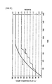
- Fig. 2 is a time chart for the operation of the conventional vehicle-drive control system.
- the fuel injection control and ignition control in the engine are stopped.
- the engine speed NE decreases gradually by friction.
- the system waits until the value of the counter indicating a crank angle reaches a start count value indicating the position to start preset brake control.
- the brake control by the generator motor is started.
- the start count value is set so as to be within the range indicating an optimum crank angle when the engine speed NE reaches 0 rpm.
- the engine speed NE decreases with the brake control, and when the engine speed NE reaches 0 rpm at timing t3, the brake control is finished. In this way, the engine is stopped at a target stop position.
- crankshaft when the vehicle-drive control systems are mounted to hybrid vehicles to execute brake control process, it will be more difficult to place the crankshaft at the optimum crank angle.
- Fig. 3 is a first speed diagram of the conventional hybrid vehicle, showing the state before starting brake control.
- Fig. 4 is a second speed diagram of the conventional hybrid vehicle, showing the state when starting the brake control.
- Fig. 5 is a third speed diagram of the conventional hybrid vehicle, showing the state during the brake control.
- the broken lines indicate the rotational speed of a ring gear, namely, a ring-gear speed NR, the rotational speed of the engine, namely, the engine speed NE, and the rotational speed of the generator, namely, a generator speed NG when the hybrid vehicle is stopped.
- the solid line indicates a state in which the engine and the drive motor are driven and the generator brake is in engagement.
- a target generator speed NG* indicating the target value of the generator speed, namely, the generator speed NG is determined from the present rotational speed of the drive motor, namely, a drive-motor speed NM, and the target generator speed NG* is gradually decreased.
- the target generator speed NG* is gradually decreased in the direction of the arrow A1 and the engine speed NE is also decreased along with it.
- the drive-motor speed NM when the ring-gear speed NR varies in the direction of the arrow A2 because of the variations in friction in the engines, the generators, etc., the variations in temperature or viscosity of the lubricating and cooling oils, or the variations in pressure in the cylinders of the engine, the drive-motor speed NM also varies to fluctuate the target generator speed NG*.
- the generator speed NG gradually decreases and so the engine speed NE gradually decreases
- the generator speed NG varies in the direction of the arrow A3 and the engine speed NE varies in the direction of the arrow A4.
- the generator When the engine cannot be stopped at the target stop position, the generator must be driven to rotate the crankshaft at a specified timing after the engine stop, giving the occupants of the vehicle a shock and uncomfortable feeling.
- a vehicle-drive control system includes target-engine-speed acquisition means for acquiring a target engine speed necessary for stopping the engine at a target angle stop position by reducing the engine speed upon demand; crank-angle acquisition means for acquiring a crank angle indicative of the position of a crankshaft; and target-engine-speed correction means for correcting the target engine speed according to the acquired crank angle.
- Another vehicle-drive control system further includes crank-angle-deviation calculation means for calculating the deviation of the crank angle from a reduction-start reference position serving as the reference to start the reduction of the engine speed according to the acquired crank angle.
- the target-engine-speed correction means corrects the target engine speed according to the deviation of the crank angle.
- Another vehicle-drive control system further includes a target deviation map in which a target deviation is set which is indicative of a deviation used as the target of the crank angle from the reduction-start reference position.
- the target-engine-speed correction means corrects the target engine speed according to the deviation between the target deviation and the calculated crank-angle deviation.
- Still another vehicle-drive control system further includes target-engine-speed correction-value calculation means for calculating the correction value of the target engine speed from the deviation.
- the target-engine-speed correction means corrects the target engine speed according to the correction value.
- Yet another vehicle-drive control system further includes stroke calculation means for calculating the stroke to the target stop position from the acquired crank angle; and rate-of-change calculation means for calculating the rate of change in target engine speed from the stroke.
- the target-engine-speed correction means corrects the target engine speed according to the rate of change.
- the stroke calculation means calculates a total stroke from a reduction start position to the target stop position from a reduction start position at the start of the reduction of the engine speed and the target stop position and calculates the stroke to the target stop position from the total stroke and the acquired crank angle.
- the rate-of-change calculation means calculates the rate of change in target engine speed from the stroke and the target engine speed.
- Another vehicle-drive control system further includes crank-angle-deviation calculation means for calculating the deviation of the crank angle from the reduction start position according to the acquired crank angle.
- the stroke calculation means calculates the stroke to the target stop position from the total stroke and the calculated crank-angle deviation.
- the target-engine-speed correction means corrects the target engine speed every correction switch timing.
- the deviation of the crank angle is the integrated value of the crank angles from the start of reduction of the engine speed.
- the target-engine-speed correction means reduces the engine speed by controlling an electric motor mechanically joined to the engine.
- Another vehicle-drive control system further includes target-electric-motor-speed calculation means for calculating target electric-motor speed from the corrected target engine speed; and electric-motor-speed control means for calculating a target electric-motor torque from the target electric-motor speed to control the torque of the electric motor.
- the engine and the electric motor are joined to different elements of a differential rotator having at least three elements and the other elements of the differential rotator are joined to the driving wheels of the vehicle.
- the target-electric-motor-speed calculation means calculates the target electric-motor speed from the target engine speed and the rotational speed of the other elements of the differential rotator.
- the target-engine-speed correction means brings the target electric-motor torque to zero when the engine speed becomes lower than a specified value.
- the specified value is set lower than the resonance speed of a damper gear disposed between the engine and the electric motor.
- the crank-angle acquisition means acquires the crank angle indicative of the position of a crankshaft, detected by a crank-angle detecting section.
- the crank-angle acquisition means acquires the crank angle indicative of the position of a crankshaft, according to the rotor position of an electric motor mechanically connected to the engine.
- the crank-angle acquisition means further includes synchronizing means for synchronizing the crank angle calculated from the rotor position with an actual crank angle.
- the synchronizing means synchronizes the crank angle with the actual crank angle when the torsion generated in a damper gear disposed between the engine and the electric motor is low and when specified synchronizing conditions for causing no torsion fluctuation are met.
- the synchronizing means synchronizes the crank angle with the actual crank angle in accordance with the difference between a crank angle detected by the crank-angle detecting section at specified timing and a crank angle calculated from the rotor position at the timing.
- engine speed is reduced; a target engine speed is acquired which is necessary for stopping the engine at a target angle stop position by reducing the engine speed upon demand; a crank angle indicative of the position of a crankshaft is acquired; and the target engine speed is acquired according to the acquired crank angle.
- a computer program for a method for controlling the drive of a vehicle said computer program is embodied on a computer-readable medium having program codes for making a vehicle-drive control system, when said program is loaded, to execute the above-mentioned method for controlling the drive of a vehicle.
- a computer functions as target-engine-speed acquisition means for acquiring a target engine speed necessary for stopping the engine at a target angle stop position by reducing the engine speed upon demand; crank-angle acquisition means for acquiring a crank angle indicative of the position of a crankshaft; and target-engine-speed correction means for correcting the target engine speed according to the acquired crank angle.
- the vehicle-drive control system includes a target-engine-speed acquisition means for reducing the engine speed to acquire a target engine speed necessary to stop the engine at a target stop position, a crank-angle acquisition means for acquiring a crank angle indicative of the position of a crankshaft, and a target-engine-speed correction means for correcting the target engine speed according to the acquired crank angle.
- a crank angle is acquired and the target engine speed is corrected according to the acquired crank angle. Accordingly, even if the friction in the engine, the electric motor, etc. varies, the temperature or viscosity of the lubricating and cooling oils varies, or the vehicle is accelerated or decelerated during reduction of the engine speed, the engine can be stopped at a target stop position. The engine can then be started at an optimum crank angle. This prevents the occurrence of a shock along with the startup.
- crankshaft there is no need to move the crankshaft to the position of an optimum crank angle after stopping the engine. This prevents the occurrence of torque fluctuations due to the rotation of the crankshaft and eliminates the need to move the crankshaft to the position of the optimum crank angle at the start of the engine to prevent the delay of engine-start timing, thus giving no uncomfortable feeling to occupants.
- Fig. 1 is a functional block diagram of a hybrid-vehicle-drive control system according to a first embodiment of the present invention.
- reference numeral 91 denotes a target-engine-speed acquisition means for decreasing the engine speed to acquire a target engine speed indicative of the target value of an engine speed necessary to stop an engine (not shown) at a target stop position
- numeral 92 denotes a crank-angle acquisition means for acquiring a crank angle indicative of the position of a crankshaft
- numeral 93 denotes a target-engine-speed correction means for correcting the target engine speed according to the obtained crank angle.
- Fig. 6 is a schematic diagram of a hybrid vehicle according to the first embodiment of the present invention.
- reference numeral 11 denotes an engine (E/G) serving as power unit disposed on a first axis
- numeral 12 denotes an output shaft (engine output shaft) disposed on the first axis for outputting the rotation generated in a crankshaft (not shown) by driving the engine 11
- numeral 13 denotes a planetary gear unit disposed on the first axis and serving as transmission and differential rotator for changing the rotation inputted through the output shaft 12
- numeral 14 denotes an output shaft disposed on the first axis for outputting the rotation changed by the planetary gear unit 13
- numeral 15 denotes a first counter-drive gear serving as output gear and fixed to the output shaft 14
- numeral 16 denotes a generator (G) disposed on the first axis and serving as a first electric motor joined to the planetary gear unit 13 through a transmission shaft 17 and also joined to the engine 11 so as to rotate differentially and mechanically.
- the generator 16 constitutes a generator motor that serves as motor and generator.
- the output shaft 12 mounts a damper gear Dp to control the rapid fluctuation of an engine torque TE transmitted through the output shaft 12.
- the damper gear Dp includes a drive plate d1 joined to the engine-side of the output shaft 12, namely, a driving part 12a; a driven plate d2 joined to the transaxle side of the output shaft 12, namely, a driven part 12b; and a spring ds connecting the drive plate d1 and the driven plate d2 together and serving as biasing member.
- the rapid fluctuation of the engine torque TE is absorbed by the spring ds.
- the output shaft 14 is shaped like a sleeve and arranged to surround the output shaft 12.
- the first counter-drive gear 15 is arranged on the side adjacent to the engine 11 with respect to the planetary gear unit 13.
- the planetary gear unit 13 includes at least a sun gear S serving as a first element, a pinion P in engagement with the sun gear S, a ring gear R serving as a second element in engagement with the pinion P, and a carrier CR serving as a third element for rotatably supporting the pinion P.
- the sun gear S is joined with the generator 16 through the transmission shaft 17.
- the ring gear R is disposed on a second axis parallel with the first axis through the output shaft 14 and a specified gear train and is joined with a drive motor (M) 25 serving as a second electric motor and a driving wheel 37 which are mechanically connected to the engine 11 and the generator 16 so as to rotate differentially.
- the carrier CR is joined with the engine 11 through the output shaft 12.
- a one-way clutch F is disposed between the carrier CR and the casing 10 of the vehicle drive system.
- the one-way clutch F is released when a normal rotation is transmitted from the engine 11 to the carrier CR and is locked when a reverse rotation is transmitted from the generator 16 or the drive motor 25 to the carrier CR to prevent the transmission of the reverse rotation to the engine 11.
- the generator 16 includes a rotor (generator rotor) 21 fixed and arranged rotatably to the transmission shaft 17, a stator 22 disposed around the rotor 21, and a coil 23 wound around the stator 22.
- the generator 16 generates electricity by the rotation transmitted through the transmission shaft 17.
- the coil 23 is connected to a battery (not shown) to feed a direct current to the battery.
- a generator brake B serving as generator fixing mechanism is disposed between the rotor 21 and the casing 10. When the generator brake B is brought into engagement, the rotor 21 can be fixed to mechanically stop the rotation of the generator 16.
- the generator brake B includes a plurality of thin plates, hydraulic servo, etc. (not shown) on the driving side and the driven side. The thin plates are pushed to one another into engagement by friction by the application of oil pressure to the hydraulic servo.
- Reference numeral 26 denotes an output shaft (drive-motor output shaft) disposed on the second axis and outputting the rotation of the drive motor 25.
- Reference numeral 27 denotes a second counter-drive gear serving as output gear fixed to the output shaft 26.
- the drive motor 25 includes a rotor 40 fixed and arranged rotatably to the output shaft 26, a stator 41 disposed around the rotor 40, and a coil 42 wound around the stator 41.
- the drive motor 25 generates a drive-motor torque TM with U-phase, V-phase, and W-phase alternating currents applied to the coil 42.
- the coil 42 is connected to the battery and a direct current from the battery is converted to the phase currents and fed to the coil 42.
- a counter shaft 30 is disposed on a third axis parallel with the first and second axes.
- a first counter-driven gear 31 and a second counter-driven gear 32 having more teeth than the first counter-driven gear 31 are fixed.
- the first counter-driven gear 31 and the first counter-drive gear 15 are brought into engagement with each other and the second counter-driven gear 32 and the second counter-drive gear 27 are brought into engagement with each other so that the rotation of the first counter-drive gear 15 is reversed and transmitted to the first counter-driven gear 31 and the rotation of the second counter-drive gear 27 is reversed and transmitted to the second counter-driven gear 32.
- a differential pinion gear 33 having fewer teeth than the first counter-driven gear 31 is fixed to the counter shaft 30.
- a differential gear 36 is disposed on a fourth axis parallel with the first to third axes such that a differential ring gear 35 of the differential gear 36 and the differential pinion gear 33 are brought into engagement.
- the rotation transmitted to the differential ring gear 35 is thus distributed by the differential gear 36 and transmitted to the driving wheel 37. Since not only the rotation generated by the engine 11 is transmitted to the first counter-driven gear 31 but also the rotation generated by the drive motor 25 can be transmitted to the second counter-driven gear 32 in this way, the hybrid vehicle can be driven by driving the engine 11 and the drive motor 25.
- Reference numeral 38 denotes a generator-rotor position sensor such as a resolver for detecting the position of the rotor 21, namely, a generator-rotor position ⁇ G;
- numeral 39 denotes a drive-motor-rotor position sensor such as a resolver for detecting the position of the rotor 40, namely, a drive-motor rotor position ⁇ M;
- numeral 52 denotes an engine speed sensor serving as engine-speed detector for detecting the engine speed NE;
- numeral 56 denotes a crank-angle sensor serving as rotational-position sensor and crank-angle sensor for sensing a crank angle ⁇ indicating the position of the crankshaft that is the rotational position of the engine 11, for which a pickup sensor is used in this embodiment.
- the detected generator-rotor position ⁇ G is sent to a vehicle control unit (not shown) and a generator control system (not shown).
- the drive-motor rotor position ⁇ M is sent to the vehicle control unit and a drive-motor control system (not shown).
- the engine speed NE and the crank angle ⁇ are sent to the vehicle control unit and an engine control unit (not shown) .
- Fig. 7 is an operation explanatory diagram of a planetary gear unit according to the first embodiment of the present invention.
- Fig. 8 is a speed diagram during normal driving according to the first embodiment of the present invention.
- Fig. 9 is a torque diagram during normal driving according to the first embodiment of the present invention.
- the carrier CR is joined with the engine 11
- the sun gear S is joined with the generator 16
- the ring gear R is joined with the drive motor 25 and the driving wheel 37 through the output shaft 14. Accordingly, the ring-gear speed NR and the rotational speed outputted to the output shaft 14, namely, the output-shaft speed become equal; the rotational speed of the carrier CR and the engine speed NE become equal; and the rotational speed of the sun gear S and the generator speed NG that is the electric-motor speed become equal.
- the equation (1) defines the rotational-speed relation of the planetary gear unit 13.
- ring gear R, the carrier CR, and the sun gear S are rotated in the normal direction during the normal driving of the hybrid vehicle and so the ring-gear speed NR, the engine speed NE, and the generator speed NG take positive values, as shown in Fig. 8. Since the ring-gear torque TR and the generator torque TG can be acquired by dividing the engine torque TE at a torque ratio determined by the number of teeth of the planetary gear unit 13, the sum of the ring-gear torque TR and the generator torque TG is the engine torque TE on the torque diagram of Fig. 9.
- Fig. 10 is a schematic diagram of a hybrid-vehicle-drive control system according to the first embodiment of the present invention.
- reference numeral 10 denotes a casing
- numeral 11 denotes an engine (E/G)
- numeral 13 denotes a planetary gear unit
- numeral 16 denotes a generator (G)
- symbol B is a generator brake for fixing the rotor 21 of the generator 16
- numeral 25 denotes a drive motor (M)
- numeral 28 denotes an inverter serving as a generator inverter for driving the generator 16
- numeral 29 denotes an inverter serving as a drive-motor inverter for driving the drive motor 25
- numeral 37 denotes a driving wheel
- numeral 38 denotes a generator-rotor position sensor
- numeral 39 denotes a drive-motor-rotor position sensor
- numeral 43 denotes a battery.
- the inverters 28 and 29 are connected to the battery 43 through a power switch SW.
- the battery 43 feeds a direct current to the inverters 28 and 29 when the power switch SW is ON.
- a generator-inverter voltage sensor 75 serving as a first DC voltage detector for detecting the DC voltage applied to the inverter 28, namely, a generator-inverter voltage VG and a generator-inverter current sensor 77 serving as a first direct-current detector for detecting the direct current supplied to the inverter 28, namely, a generator inverter current IG are disposed on the inlet side of the inverter 28.
- a drive-motor-inverter voltage sensor 76 serving as a second DC voltage detector for detecting the DC voltage fed to the inverter 29, namely, a drive-motor inverter voltage VM and a drive-motor inverter current sensor 78 serving as a second direct-current detector for detecting the direct current fed to the inverter 29, namely, a drive-motor inverter current IM are disposed on the inlet side of the inverter 29.
- the generator-inverter voltage VG and the generator inverter current IG are sent to a generator control system 47 and a vehicle control unit 51, while the drive-motor inverter voltage VM and the drive-motor inverter current IM are sent to a drive-motor control system 49 and the vehicle control unit 51.
- a smoothing capacitor C is connected between the battery 43 and the inverters 28 and 29.
- the vehicle control unit 51 includes a CPU, a recording device, etc. (not shown), which controls the entire hybrid-vehicle drive system and functions as a computer according to various programs and data.
- the vehicle control unit 51 is connected to an engine control unit 46, the generator control system 47, and the drive-motor control system 49.
- the engine control unit 46 includes a CPU, a recording device, etc. (not shown) and transmits instruction signals of a throttle opening ⁇ , valve timing, etc. to the engine 11 to control the engine 11.
- the generator control system 47 includes a CPU, a recording device, etc. (not shown) and transmits a driving signal SG1 to the inverter 28 to control the generator 16.
- the drive-motor control system 49 includes a CPU, a recording device, etc.
- the engine control unit 46, the generator control system 47, and the drive-motor control system 49 constitute a first control system located downward from the vehicle control unit 51, while the vehicle control unit 51 constitutes a second control system located upward from the engine control unit 46, the generator control system 47, and the drive-motor control system 49.
- the engine control unit 46, the generator control system 47, and the drive-motor control system 49 also function as computer according to various programs and data.
- the inverter 28 is driven in accordance with the driving, signal SG1 and, upon powering, is given a direct current from the battery 43 to generate phase currents IGU, IGV, and IGW and feeds them to the generator 16, while at regeneration, it is given the phase currents IGU, IGV, and IGW from the generator 16 to generate a direct current and feeds it to the battery 43.
- the inverter 29 is driven in accordance with the driving signal SG2 and, upon powering, is given a direct current from the battery 43 to generate phase currents IMU, IMV, and IMW and feeds them to the drive motor 25, while at regeneration, it is given the phase currents IMU, IMV, and IMW from the drive motor 25 to generate a direct current and feeds it to the battery 43.
- Reference numeral 44 denotes a battery indicator for sensing the condition of the battery 43, namely, a battery remaining amount SOC which is battery condition;
- numeral 52 denotes an engine speed sensor;
- numeral 53 denotes a shift position sensor for detecting the position of a shift lever (not shown) serving as speed control means, namely, a shift position SP;
- numeral 54 denotes an accelerator pedal;
- numeral 55 denotes an accelerator switch serving as an accelerator-operation detector for detecting the position (depression) of the accelerator pedal 54, namely, an accelerator-pedal position AP;
- numeral 56 denotes a crank-angle sensor;
- numeral 61 denotes a brake pedal for applying brakes (not shown);
- numeral 62 denotes a brake switch serving as a brake-operation detector for detecting the position (depression) of the brake pedal 61, namely, a brake-pedal position BP;
- numeral 63 denotes an engine-temperature sensor for sensing the temperature
- Numerals 66 to 69 denote current sensors serving as AC current detector for detecting the phase currents IGU, IGV, IMU, and IMV; and numeral 72 denotes a battery-voltage sensor serving as a voltage sensor for the battery 43 for detecting a battery voltage VB which is the battery condition.
- the battery voltage VB and the battery remaining amount SOC are sent to the generator control system 47, the drive-motor control system 49, and the vehicle control unit 51.
- the battery conditions may include a battery current, a battery temperature, etc.
- the battery indicator 44, the battery-voltage sensor 72, a battery current sensor (not shown), and a battery-temperature sensor (not shown) constitute a battery-condition sensor.
- the detected currents IGU and IGV are sent to the generator control system 47 and the vehicle control unit 51, while the currents IMU and IMV are sent to the drive-motor control system 49 and the vehicle control unit 51.
- the vehicle control unit 51 transmits an engine control signal to the engine control unit 46 and sets the drive/stop of the engine 11 with the engine control unit 46.
- a vehicle-speed calculation means (not shown) of the vehicle control unit 51 calculates the vehicle speed to determine the rate of change ⁇ M of the drive-motor rotor position ⁇ M and calculates a vehicle speed V from the rate of change ⁇ M and a gear ratio ⁇ V in the torque transmission system from the output shaft 26 to the driving wheel 37.
- the vehicle control unit 51 determines a target engine speed NE* indicating the target value of the engine speed NE, a target generator torque TG* that is a target electric-motor torque indicating the target value of the generator torque TG, and a target drive-motor torque TM* indicating the target value of the drive-motor torque TM and sends them to the engine control unit 46, the generator control system 47, and the drive-motor control system 49, respectively.
- the generator control system 47 sets a target generator speed NG* that is a target electric-motor speed indicating the target value of the generator speed NG.
- the drive-motor control system 49 sets a drive-motor-torque correction value ⁇ TM indicating the correction value of the drive-motor torque TM.
- the target engine speed NE*, the target generator torque TG*, and the target drive-motor torque TM* constitute control instruction values.
- a generator-speed calculation means (not shown) of the generator control system 47 executes generator-speed calculation process to calculate the generator speed NG by reading the generator-rotor position ⁇ G and calculating the rage of change ⁇ G of the generator-rotor position ⁇ G.
- a drive-motor speed calculation means (not shown) of the drive-motor control system 49 executes drive-motor speed calculation process to calculate the rotational speed of the drive motor 25, namely, a drive motor speed NM by reading the drive-motor rotor position ⁇ M and calculating the rate of change ⁇ M of the drive-motor rotor position ⁇ M.
- the generator-rotor position sensor 38 and the generator-speed calculation means can be used as rotational-speed sensor for sensing the generator speed NG
- the drive-motor-rotor position sensor 39 and the drive-motor-speed calculation means can be used as rotational-speed sensor for sensing the drive-motor speed NM
- the drive-motor-rotor position sensor 39 and the vehicle-speed calculation means can be used as vehicle-speed sensor for sensing the vehicle speed V.
- the engine speed NE is sensed by the engine speed sensor 52 in this embodiment, it can also be calculated by the engine control unit 46.
- the vehicle speed V is calculated by the vehicle-speed calculation means in accordance with the drive-motor rotor position ⁇ M in this embodiment, it is also possible to detect the ring-gear speed NR and calculate the vehicle speed V from the ring-gear speed NR or, alternatively, from the rotational speed of the driving wheel 37, namely, a driving-wheel speed.
- a ring-gear speed sensor, a driving-wheel speed sensor, etc. are disposed as vehicle-speed sensor.
- Fig. 11 is a first main flowchart for the operation of the hybrid-vehicle-drive control system according to the first embodiment of the present invention
- Fig. 12 is a second main flowchart for the operation of the hybrid-vehicle-drive control system according to the first embodiment of the present invention
- Fig. 13 is a third main flowchart for the operation of the hybrid-vehicle-drive control system according to the first embodiment of the present invention
- Fig. 14 is a diagram of a first vehicle-torque-requirement map according to the first embodiment of the present invention
- Fig. 15 is a diagram of a second vehicle-torque-requirement map according to the first embodiment of the present invention
- Fig. 11 is a first main flowchart for the operation of the hybrid-vehicle-drive control system according to the first embodiment of the present invention
- Fig. 12 is a second main flowchart for the operation of the hybrid-vehicle-drive control system according to the first embodiment of the
- FIG. 16 is a diagram of a target-engine-operating-condition map according to the first embodiment of the present invention
- Fig. 17 is an engine-drive-region map according to the first embodiment of the present invention.
- the horizontal axis is scaled in terms of the vehicle speed V; the vertical axis is scaled in a vehicle torque requirement TO*.
- the horizontal axis is scaled in terms of the engine speed NE; the vertical axis is scaled in the engine torque TE.
- An initializing means (not shown) of the vehicle control unit 51 (see Fig. 10) first initializes various variables by initializing process.
- the vehicle control unit 51 then reads the accelerator-pedal position AP from the accelerator switch 55 and the brake-pedal position BP from the brake switch 62.
- the vehicle-speed calculation means reads the drive-motor rotor position ⁇ M, calculates the rate of change ⁇ M of the drive-motor rotor position ⁇ M, and calculates the vehicle speed V from the rate of change ⁇ M and the gear ratio ⁇ V.
- a vehicle-torque-requirement determination means (not shown) of the vehicle control unit 51 then executes vehicle-torque-requirement determination process to determine the vehicle torque requirement TO* necessary to drive the hybrid vehicle, which is preset in correspondence with the vehicle speed V and the accelerator-pedal position AP or the brake-pedal position BP, with reference to the first vehicle-torque-requirement map of Fig. 14, which is recorded in the recording device of the vehicle control unit 51, when the accelerator pedal 54 is depressed, while with reference to the second vehicle-torque-requirement map of Fig. 15, which is recorded in the recording device, when the brake pedal 61 is depressed.
- the vehicle control unit 51 determines whether the vehicle torque requirement TO* is higher than a drive-motor maximum torque TMmax preset as the rating of the drive motor 25. When the vehicle torque requirement TO* is higher than the drive-motor maximum torque TMmax, the vehicle control unit 51 determines whether the engine 11 is stopped, wherein when the engine 11 is stopped, a rapid-acceleration control means (not shown) of the vehicle control unit 51 executes rapid acceleration control process to drive the drive motor 25 and the generator 16, thereby driving the hybrid vehicle.
- a battery-charge/discharge-output-requirement calculation means (not shown) of the vehicle control unit 51 executes battery-charge/discharge-output-requirement calculation process to read the battery remaining amount SOC from the battery indicator 44 and calculate a battery-charge/discharge output requirement PB from the battery remaining amount SOC.
- a target-engine-operating-condition setting means (not shown) of the vehicle control unit 51 executes target-engine-operating-condition setting process to determine points A1 to A3, or Am, at which lines PO1, PO2, ⁇ indicating the vehicle output requirement PO intersect an optimum fuel efficiency curve L indicating the highest efficiency of the engine 11 at accelerator-pedal positions AP1 to AP6 as operating point of the engine 11 under target engine operating condition, determine engine torques TE1 to TE3, or TEm, at the operating point as a target engine torque TE* indicating the target value of the engine torque TE, and determine engine speeds NE1 to NE3, or NEm, at the operating point as the target engine speed NE*, with reference to the target-engine-operating-condition map of Fig. 16, which is recorded in the recording device of the vehicle control unit 51.
- the vehicle control unit 51 determines whether the engine 11 is in an operating region AR1 with reference to the engine drive region map of Fig. 17, which is recorded in the recording device of the vehicle control unit 51.
- symbol AR1 indicates a drive region where the engine 11 is driven
- symbol AR2 indicates a stop region where the drive of the engine 11 is stopped
- symbol AR3 indicates a hysteresis region.
- Symbol LE1 indicates a line where the stopped engine 11 is driven; and symbol LE2 indicates a line where the drive of the driven engine 11 is stopped.
- the larger the battery remaining amount SOC the more the line LE1 is shifted to the right in Fig. 17 to decrease the drive region AR1; the smaller the battery remaining amount SOC is, the more the line LE1 is shifted to the left in Fig. 17 to increase the drive region AR1.
- an engine-start control means (not shown) of the vehicle control unit 51 executes engine-start control process to send the target engine speed NE* to the engine control unit 46 and so the engine control unit 46 starts the engine 11.
- an engine-stop control means (not shown) of the vehicle control unit 51 executes engine-stop control process to stop the operation of the engine 11.
- a target-drive-motor-torque calculation means (not shown) of the vehicle control unit 51 executes target-drive-motor-torque calculation process to calculate and determine the vehicle torque requirement TO* as a target drive-motor torque TM* and send it to the drive-motor control system 49.
- a drive-motor control means (not shown) of the drive-motor control system 49 executes drive-motor control process to control the torque of the drive motor 25.
- an engine control means (not shown) of the engine control unit 46 executes engine control process to control the engine 11 according to the target engine speed NE* by a specified method so that the engine speed NE reaches the target engine speed NE*.
- a target-generator-speed calculation means (not shown) of the generator control system 47 which serves as target-electric-motor-speed calculation means, executes target-generator-speed calculation process serving as target-electric-motor-speed calculation process and, specifically, reads the drive-motor rotor position ⁇ M from the drive-motor-rotor position sensor 39 and calculates the ring-gear speed NR from the drive-motor rotor position ⁇ M and a gear ratio ⁇ R from the output shaft 26 (see Fig.
- a engagement-condition determination means (not shown) of the generator control system 47 therefore executes engagement-condition determination process to determine whether specified engaging conditions are met depending on whether the absolute value of the generator speed NG is smaller than a threshold NGth1.
- the generator control system 47 determines whether the generator brake B is in engagement when the engaging conditions are met and the absolute value of the generator speed NG is smaller than the threshold NGth1.
- a generator-brake engagement control means (not shown) of the generator control system 47 executes generator-brake engagement control process to turn on a brake signal indicating a generator-brake engaging requirement that requires the engagement of the generator brake B, turning on a brake solenoid to apply a brake hydraulic pressure Pb to the hydraulic servo, thereby bringing the generator brake B into engagement.
- the generator speed NG reaches 0 rpm while the ring-gear speed NR and the engine speed NE amount to specified values.
- the generator control system 47 determines whether the generator brake B has been released.
- a generator-speed control means (not shown) of the generator control system 47, which serves as electric-motor-speed control means, executes generator-speed control process serving as electric-motor-speed control process to control the torque of the generator 16 according to the generator speed NG.
- a generator-brake-release control means (not shown) of the generator control system 47 executes generator-brake-release control process to turn off the brake signal, thus turning off the brake solenoid to drain the brake hydraulic pressure Pb from the hydraulic servo, thereby releasing the generator brake B.
- the engine torque TE, the ring-gear torque TR, and the generator torque TG apply reaction forces to one another, so that the generator torque TG is converted to the ring-gear torque TR and is outputted from the ring gear R.
- the ring-gear torque TR is varied with an inertia torque TGI of the rotor 21 and its rotor shaft, which is produced by the change of the generator speed NG, the changed ring-gear torque TR is transmitted to the driving wheel 37 to reduce the drive feeling of the hybrid vehicle.
- the ring-gear torque TR is therefore calculated in view of the inertia torque TGI associated with the change of the generator speed NG.
- a ring-gear-torque calculation means (not shown) of the vehicle control unit 51 executes ring-gear-torque calculation process to calculate a ring-gear torque TR from the target generator torque TG* and the ratio of the number of teeth of the ring gear R to that of the sun gear S.
- the inertia torque TGI generally takes a positive value in the direction of acceleration during acceleration of hybrid vehicles, while it takes a negative value in the direction of acceleration during deceleration of hybrid vehicles.
- the angular acceleration ⁇ G can be calculated by differentiating the generator speed NG.
- the ring-gear torque TR can be written as because the ring-gear torque TR is ⁇ times as much as a sun-gear torque TS. In this way, the ring-gear torque TR can be calculated from the target generator torque TG* and the inertia torque TGI.
- a drive-shaft-torque estimation means (not shown) of the vehicle control unit 51 executes drive-shaft-torque estimation process to estimate the torque of the output shaft 26, namely, a drive-shaft torque TR/OUT from the target generator torque TG* and the inertia torque TGI.
- the drive-shaft-torque estimation means estimates and calculates the drive-shaft torque TR/OUT from the ring-gear torque TR and the ratio of the number of teeth of the second counter-drive gear 27 to that of the ring gear R.
- the drive-shaft-torque estimation means reads the engine torque TE from the engine control unit 46 and calculates the ring-gear torque TR from the engine torque TE by the torque relation and estimates the drive-shaft torque TR/OUT from the ring-gear torque TR and the ratio of the number of teeth of the second counter-drive gear 27 to that of the ring gear R.
- the target drive-motor-torque calculation means executes target drive-motor-torque calculation process to calculate and determine deficiency of the drive-shaft torque TR/OUT as the target drive-motor torque TM* by subtracting the drive-shaft torque TR/OUT from the vehicle torque requirement TO* and send the determined target drive-motor torque TM* to the drive-motor control system 49.
- the drive-motor control means then executes drive-motor control process to control the torque of the drive motor 25 according to the determined target drive-motor torque TM*, thereby controlling the drive-motor torque TM.
- Fig. 18 is a diagram of the subroutine of the rapid-acceleration control process according to the first embodiment of the present invention.
- the rapid-acceleration control means reads the vehicle torque requirement TO*, in which case since the vehicle torque requirement TO* is higher than the drive-motor maximum torque TMmax, the target drive-motor-torque calculation means sets the target drive-motor torque TM* at the drive-motor maximum torque TMmax and sends the target drive-motor torque TM* to the drive-motor control system 49.
- a target-generator-torque calculation means (not shown) of the vehicle control unit 51 (see Fig. 10) executes target-generator-torque calculation process to calculate the difference torque ⁇ T between the vehicle torque requirement TO* and the target drive-motor torque TM*, calculate and determine the deficiency of the drive-motor maximum torque TMmax which is the target drive-motor torque TM* as the target generator torque TG*, and send the target generator torque TG* to the generator control system 47.
- the drive-motor control means executes drive-motor control process to control the torque of the drive motor 25 according to the target drive-motor torque TM*.
- a generator-torque control means (not shown) of the generator control system 47 executes generator-torque control process to control the torque of the generator 16 according to the target generator torque TG*.
- Fig. 19 is a diagram of the subroutine of the drive-motor control process according to the first embodiment of the present invention.
- the drive-motor control means first reads the target drive-motor torque TM*.
- the drive-motor-speed calculation means reads the drive-motor rotor position ⁇ M and calculates the rate of change ⁇ M of the drive-motor rotor position ⁇ M, thereby calculating the drive-motor speed NM.
- the drive-motor control means reads the battery voltage VB. The actual measurement is defined by the drive-motor speed NM and the battery voltage VB.
- the drive-motor control means calculates and determines a d-axis-current instruction value IMd* and a q-axis-current instruction value IMq* from the target drive-motor torque TM*, the drive-motor speed NM, and the battery voltage VB with reference to the current-instruction-value map for controlling the drive motor, which is recorded in the recording device of the drive-motor control system 49 (see Fig. 10).
- the d-axis-current instruction value IMd* and the q-axis-current instruction value IMq* define an AC-current instruction value for the drive motor 25.
- the current IMW can be detected by a current sensor, as with the currents IMU and IMV.
- An AC-current calculation means of the drive-motor control means executes AC-current calculation process to perform three-phase/two-phase conversion, converting the currents IMU, IMV, and IMW to an alternating d-axis current IMd and q-axis current IMq, thereby calculating the d-axis current IMd and the q-axis current IMq.
- An AC-voltage instruction-value calculation means of the drive-motor control means executes AC-voltage instruction-value calculation process to calculate voltage instruction values VMd* and VMq* from the d-axis current IMd, the q-axis current IMq, d-axis-current instruction value IMd*, and the q-axis-current instruction value IMq*.
- the drive-motor control means performs two-phase/three-phase conversion to convert the voltage instruction values VMd* and VMq* to voltage instruction values VMU*, VMV*, and VMW*, thereby calculating pulse-width modulating signals Su, Sv, and Sw from the voltage instruction values VMU*, VMV*, and VMW*, and outputs the pulse-width modulating signals Su, Sv, and Sw to a drive process means (not shown) of the drive-motor control system 49.
- the drive process means executes drive process to send a drive signal SG2 according to the pulse-width modulating signals Su, Sv, and Sw to the inverter 29.
- the voltage instruction values VMd* and VMq* define an AC-voltage instruction value for the drive motor 25.
- step S27 and step S7-4 Only step S7-4 will be described.
- Fig. 20 is a diagram of the subroutine of the generator-torque control process according to the first embodiment of the present invention.
- the generator-torque control means reads the target generator torque TG* and the generator-rotor position ⁇ G, calculates the generator speed NG from the generator-rotor position ⁇ G, and then reads the battery voltage VB.
- the generator-torque control means then calculates and determines a d-axis-current instruction value IGd* and a q-axis-current instruction value IGq* from the target generator torque TG*, the generator speed NG, and the battery voltage VB with reference to the current-instruction-value map for controlling the generator, which is recorded in the recording device of the generator control system 47 (see Fig. 10).
- the d-axis-current instruction value IGd* and the q-axis-current instruction value IGq* define an AC-current instruction value for the generator 16.
- the current IGW can be detected by a current sensor, as with the currents IGU and IGV.
- An AC-current calculation means of the generator-torque control means executes AC-current calculation process to perform three-phase/two-phase conversion, converting the currents IGU, IGV, and IGW to a d-axis current IGd and a q-axis current IGq, thereby calculating the d-axis current IGd and the q-axis current IGq.
- An AC-current-voltage instruction-value calculation means of the generator-torque control means executes AC-voltage instruction-value calculation process to calculate voltage instruction values VGd* and VGq* from the d-axis current IGd, the q-axis current IGq, d-axis-current instruction value IGd*, and the q-axis-current instruction value IGq*.
- the generator-torque control means performs two-phase/three-phase conversion to convert the voltage instruction values VGd* and VGq* to voltage instruction values VGU*, VGV*, and VGW*, calculates the pulse-width modulating signals Su, Sv, and Sw from the voltage instruction values VGU*, VGV*, and VGW*, and outputs the pulse-width modulating signals Su, Sv, and Sw to a drive process means (not shown) of the generator control system 47.
- the drive process means executes drive process to send a drive signal SG1 according to the pulse-width modulating signals Su, Sv, and Sw to the inverter 28.
- the voltage instruction values VGd* and VGq* define an AC-voltage instruction value for the generator 16.
- Fig. 21 is a diagram of the subroutine of the engine-start control process according to the first embodiment of the present invention.
- the engine-start control means reads the throttle opening ⁇ , wherein when the throttle opening ⁇ is 0%, it reads the vehicle speed V calculated by the vehicle-speed calculation means and also reads the operating point of the engine 11 (see Fig. 10) determined by the target engine-operating-condition setting process.
- the target-generator-speed calculation means executes the target-generator-speed calculation process to read the drive-motor rotor position ⁇ M and calculate the ring-gear speed NR from the drive-motor rotor position ⁇ M and the gear ratio ⁇ R, read the target engine speed NE* in the operating point, calculate and determine the target generator speed NG* from the ring-gear speed NR and the target engine speed NE* by the rotational-speed relation, and send it to the generator control system 47.
- the engine-start control means compares the engine speed NE with a preset starting speed NEth1 to determine whether the engine speed NE is higher than the starting speed NEth1. When the engine speed NE is higher than the starting speed NEth1, the engine-start control means sends an instruction to start the engine 11 to the engine control unit 46.
- An engine start means (not shown) of the engine control unit 46 executes engine-start process to emit a jet of fuel to the engine 11 and ignite it.
- the generator-speed control means executes generator-speed control process according to the target generator speed NG* to increase the generator speed NG and also increase the engine speed NE along with that.
- the drive-shaft-torque estimation means estimates the drive-shaft torque TR/OUT and the target drive-motor torque calculation means calculates and determines the target drive-motor torque TM* and sends it to the drive-motor control system 49.
- the drive-motor control means controls the torque of the drive motor 25 according to the target drive-motor torque TM*, thereby controlling the drive-motor torque TM.
- the engine-start control means controls the throttle opening ⁇ so that the engine speed NE reaches the target engine speed NE*.
- the engine-start control means determines whether the generator torque TG is lower than a motoring torque TEth associated with the starting of the engine 11 in order to determine whether the engine 11 is normally operated and stands by for a specified time with the generator torque TG lower than the motoring torque TEth.
- the generator-speed control means executes generator-speed control process according to the target generator speed NG*, then, as in steps S25 to S27, the drive-shaft-torque estimation means estimates the drive-shaft torque TR/OUT, the target-drive-motor-torque calculation means calculates and determines the target drive-motor torque TM* and sends it to the drive-motor control system 49.
- the drive-motor control means controls the torque of the drive motor 25 according to the target drive-motor torque TM* to control the drive-motor torque TM.
- Fig. 22 is a diagram of the subroutine of the generator-speed control process according to the first embodiment of the present invention.
- the generator-speed control means reads the target generator speed NG* and generator speed NG, executes PI control according to the speed difference ⁇ NG between the target generator speed NG* and the generator speed NG to calculate and determine the target generator torque TG*.
- the generator-torque control means executes the generator-torque control process of Fig. 20 to control the torque of the generator 16 (see Fig. 6).
- Fig. 23 is a diagram of the subroutine of the generator-brake-engagement control process according to the first embodiment of the present invention.
- the generator-brake-engagement control means turns the brake signal from OFF to ON and sets the target generator speed NG* to 0 rpm.
- the drive-shaft-torque estimation means estimates the drive-shaft torque TR/OUT
- the target-drive-motor-torque calculation means calculates and determines the target drive-motor torque TM* and sends it to the drive-motor control system 49
- the drive-motor control means controls the torque of the drive motor 25 according to the target drive-motor torque TM*, thereby controlling the drive-motor torque TM, as in steps S25 to S27.
- the generator-brake-engagement control means determines whether the absolute value of the generator speed NG is smaller than a specified rotational speed Nth1 (for example, 100 rpm), wherein when the absolute value of the generator speed NG is smaller than the rotational speed Nth1, it brings the generator brake B into engagement.
- the drive-shaft-torque estimation means estimates the drive-shaft torque TR/OUT
- the target-drive-motor-torque calculation means calculates and determines the target drive-motor torque TM* and sends it to the drive-motor control system 49
- the drive-motor control means controls the torque of the drive motor 25 according to the target drive-motor torque TM*, thereby controlling the drive-motor torque TM, as in steps S25 to S27.
- the generator-brake-engagement control means stops the switching to the generator 16 to shut down the generator 16.
- Fig. 24 is a diagram of the subroutine of the generator-brake-release control process according to the first embodiment of the present invention.
- the specified engine torque TE is applied to the rotor 21 of the generator 16 as a reaction force while the generator brake B (see Fig. 10) is in engagement. Accordingly, when the generator brake B is simply released, the generator torque TG and the engine torque TE vary greatly as the engine torque TE is transmitted to the rotor 21, causing a shock.
- the engine torque TE transmitted to the rotor 21 is estimated or calculated and the generator-brake-release control means reads a torque corresponding to the estimated or calculated engine torque TE, namely, the equivalent of engine torque, and sets it as the target generator torque TG*. Subsequently, after the generator-torque control means has executed the generator-torque control process of Fig.
- the drive-shaft-torque estimation means estimates the drive-shaft torque TR/OUT
- the target-drive-motor-torque calculation means calculates and determines the target drive-motor torque TM* and sends it to the drive-motor control system 49
- the drive-motor control means of the drive-motor control system 49 controls the torque of the drive motor 25 according to the target drive-motor torque TM*, thereby controlling the drive-motor torque TM, as in steps S25 to S27.
- the generator-brake-release control means releases the generator brake B and sets the target generator speed NG* to 0 rpm.
- the generator-speed control means then executes the generator-speed control process of Fig. 22.
- the drive-shaft-torque estimation means estimates the drive-shaft torque TR/OUT
- the target-drive-motor-torque calculation means calculates and determines the target drive-motor torque TM* and sends it to the drive-motor control system 49
- the drive-motor control means of the drive-motor control system 49 controls the torque of the drive motor 25 according to the target drive-motor torque TM*, thereby controlling the drive-motor torque TM, as in steps S25 to S27.
- the engine-torque equivalent is estimated or calculated by learning the torque ratio of the generator torque TG to the engine torque TE.
- Fig. 25 is a diagram of the subroutine of the engine-stop control process according to the first embodiment of the present invention
- Fig. 26 is a diagram of the subroutine of an engine-speed reducing process according to the first embodiment of the present invention
- Fig. 27 is a diagram of a first condition of the engine according to the first embodiment of the present invention
- Fig. 28 is a diagram of a second condition of the engine according to the first embodiment of the present invention
- Fig. 29 is a time chart for the operation of the engine-stop control process according to the first embodiment of the present invention
- Fig. 30 is a first diagram of a target-integrated-value map according to the first embodiment of the present invention
- FIG. 31 is a second diagram of the target-integrated-value map according to the first embodiment of the present invention
- Fig. 32 is a graph of the correction value of the target engine speed according to the first embodiment of the present invention
- Fig. 33 is a graph of the operation of a target-engine-speed correction process according to the first embodiment of the present invention.
- the horizontal axis is scaled in terms of time; the vertical axis is scaled in a target integrated value ⁇ *.
- the horizontal axis is scaled in terms of time; the vertical axis is scaled in an integrated value ⁇ , the target integrated value ⁇ *, and a correction value ⁇ NE*.
- the horizontal axis is scaled in terms of time; the vertical axis is scaled in the target engine speed NE* and the correction value ⁇ NE*.
- the engine 11 (see Fig. 10) and the drive motor 25 are first driven so that, when the engine 11 shifts from the operating region AR1 to the stop region AR2 shown in Fig.17 while the engine 11 is driven according to the target engine speed NE* and the drive motor 25 is driven according to a target drive-motor speed NM*, the engine-stop control means determines whether the generator brake B has been released. When the generator brake B has not been released and is in engagement, an instruction to release the generator brake B is sent to the generator control system 47 and the generator-brake-release control means executes generator-brake-release control process of Fig. 24 to release the generator brake B.
- the engine-stop control means issues an engine stop request to the engine control unit 46 at timing t11 to stop the fuel injection and ignition of the engine 11, thereby bringing the throttle opening ⁇ into 0%.
- the engine 11 generally includes a plurality of cylinders, in which the pistons are joined together with a crankshaft.
- the cylinders suck air and are subjected to the processes (brought into conditions) of aspiration by which fuel is injected, compression by which the mixture of air and fuel is compressed, combustion by which the mixture is ignited, and exhaustion by which exhaust gas after the combustion is exhausted.
- reference numeral 101 denotes a cylinder
- numeral 102 denotes a piston which reciprocates in the cylinder 101
- numeral 103 denotes a piston rod connected between the piston 102 and a crankshaft (not shown) such that it oscillates freely
- numeral 105 denotes an intake valve for sucking air
- numeral 106 denotes an exhaust valve for letting out the exhaust gas.
- the four cylinders 101 are arranged adjacent to one another and the pistons 102 in the cylinders 101 are each joined with the crankshaft through the piston rods 103 and reciprocate through the top dead center, the midpoint, and the bottom dead center.
- the numbers of the cylinders 101, or the cylinder numbers are #1 to #4 and the ignition order is #1 ⁇ #3 ⁇ #4 ⁇ #2 for a four-cylinder engine.
- the cylinder 101 of No. #1 is subjected to the combustion process
- the cylinders 101 of Nos. #2 to #4 are subjected to the exhaustion process, the compression process, and the aspiration process, respectively as shown in Fig. 27 and Fig 28.
- the force necessary to move the pistons 102 is large in the cylinders 101 of Nos. #1 and #3 and is small in the cylinders 101 of Nos. #2 and #4.
- the tops of the pistons 102 in the cylinders 101 of Nos. #1 and #4 are located between the midpoint and the bottom dead center of the combustion process and the aspiration process, respectively, while the tops of the pistons 102 in the cylinders 101 of Nos. #2 and #3 are located between the top dead center and the midpoint of the exhaustion process and the compression process, respectively.
- the shock generated at the start of the engine 11 is reduced.
- the crankshaft of the engine 11 at an optimum crank angle at the start of the engine 11 when the position of the crankshaft of the engine 11 is expressed in terms of the crank angle p prevents the occurrence of shock with the startup. Accordingly, in this embodiment, to stop the engine 11, the position of the optimum crank angle is set as a target stop position and the crankshaft is placed at the target stop position. In other words, the engine 11 is stopped at the target stop position.
- the engine-stop control means reads a generator-mode switching signal generated in the vehicle control unit 51 at timing t12, sets the target engine speed NE* to an idling speed Nid (for example, 900 rpm) that is a threshold, and waits for the engine speed NE to reach the idling speed Nid.
- idling speed Nid for example, 900 rpm
- an engine-speed reduction means of the engine-stop control means starts engine-speed reduction process. More specifically, a preprocess means of the engine-speed reduction means executes preprocess to start timing with a timer built in the vehicle control unit 51 and drive the generator 16, thereby operating the engine 11 with no load at the idling speed Nid for time ⁇ 1 (for example, 500 ms). This eliminates the variation in pressure in the cylinders 101 of the engine 11 after the fuel injection and ignition have been stopped.
- a reduction-start-reference-position detection means of the engine-speed reduction means starts reduction-start-reference-position detection process at timing t14 to read the crank angle ⁇ from the crank-angle sensor 56 and detect the reduction-start reference position serving as the reference to start the reduction of the engine speed NE when the engine 11 is stopped at a target stop position according to the crank angle ⁇ .
- the reduction-start reference position is calculated, set, and expressed in terms of the crank angle ⁇ in advance from the target stop position, the moving time when the crankshaft is moved to the target stop position, moving speed, etc.
- the reduction-start-reference-position detection process is started and, after a lapse of a specified time ⁇ 2 (for example, 2 to 1,000 ms) from the detection of the reduction-start reference position at timing t15 the engine-speed reduction means starts to reduce the engine speed NE.
- a specified time ⁇ 2 for example, 2 to 1,000 ms
- the engine speed NE reaches 0 rpm in a specified time ⁇ 3, 1,000 ms in this embodiment, and the position of the crankshaft is moved from the reduction-start reference position to the target stop position.
- the target-engine-speed acquisition means 91 (see Fig. 1) of the engine-speed reduction means executes target-engine-speed acquisition process to acquire the target engine speed NE* after the start of the reduction of the engine speed NE until the engine speed NE reaches 0 rpm by sequentially calculating the following expression.
- the target engine speed NE* can be set in advance in correspondence with the elapsed time after the start of reduction of the engine speed NE and recorded as target-engine-speed map in the recording device of the vehicle control unit 51.
- the engine-speed reduction means acquires the target engine speed NE* by reading the target engine speed NE* corresponding to the elapsed time after the start of reduction of the engine speed NE with reference to the target-engine-speed map.
- the value ⁇ NE* for calculating the target engine speed NE* is set according to the engine speed NE when the reduction-start reference position was detected and the time ⁇ 3 as follows: Since the engine speed NE at the time when the reduction-start reference position was detected is 900 rpm in this embodiment, the engine speed NE must be brought from 900 rpm to 0 rpm while the position of the crankshaft moves from the reduction-start reference position to the target stop position.
- the initial value of the target engine speed NE* is set to 900 rpm and the value ⁇ NE* which is subtracted from the target engine speed NE* each time control timing has passed after the start of reduction of the engine speed NE can be calculated using the deceleration ⁇ .
- the target-generator-speed calculation means of the engine-speed reduction means executes target-generator-speed calculation process to read the ring-gear speed NR and the target engine speed NE*, calculate target generator speed NG* from the ring-gear speed NR and the target engine speed NE* by the rotational-speed relation, and send it to the generator control system 47.
- the generator control system 47 executes the generator-speed control process of Fig. 22 to control the rotational speed of the generator 16 so that the generator speed NG reaches the target generator speed NG*.
- the drive-shaft-torque estimation means estimates the drive-shaft torque TR/OUT and the target drive-motor torque calculation means calculates and determines the target drive-motor torque TM* and sends it to the drive-motor control system 49.
- the drive-motor control means controls the torque of the drive motor 25 according to the target drive-motor torque TM*, thereby controlling the drive-motor torque TM.
- the target engine speed NE* is acquired, the target generator speed NG* is calculated from the target engine speed NE*, and the rotational speed of the generator 16 is controlled to gradually reduce the engine speed NE.
- the target engine speed NE* is switched by correction every specified correction switch timing.
- the deviation of the theoretical crank angle ⁇ from the reduction-start reference position when the engine speed NE is reduced at the deceleration ⁇ is calculated in advance as an integrated value which is the target of the crank angle ⁇ and is set as the target integrated value ⁇ * indicative of a target deviation.
- the target integrated value ⁇ * is set as the target deviation map and the target integrated-value map, shown in Figs. 30 and 31, in correspondence with the elapsed time from the start of reduction of the engine speed NE and is recorded in the recording device of the vehicle control unit 51.
- the target integrated value ⁇ * is set as index values within the range from 0 to 1,000 indicative of the position of a flywheel (not shown) joined with the crankshaft.
- crank-angle acquisition means 92 of the engine-speed reduction means executes crank-angle acquisition process to read and acquire an actual crank angle ⁇ every control timing.
- An integrated-value calculation means serving as crank-angle-deviation calculation means of the engine-speed reduction means executes integrated-value calculation process serving as the crank-angle-deviation calculation process to calculate the integrated value ⁇ that is the deviation of the crank angle ⁇ from the reduction-start reference position.
- the integrated value ⁇ can be acquired by calculating the amount of change ⁇ of the crank angle ⁇ every control timing with the initial value at 0 and by integrating them.
- a target-engine-speed correction-value calculation means of the engine-speed reduction means executes target-engine-speed correction-value calculation process to determine whether the timing is correction switch timing, wherein when it is the correction switch timing, the correction value ⁇ NE* of the target engine speed NE* is calculated.
- the correction switch timing is set at an interval longer than the control timing, for example, every 50 ms. Since the engine speed NE in the embodiment must be brought to 0 rpm in 1,000 ms, 20 correction switch timings are set.
- the correction value ⁇ NE* takes a positive value
- the correction value ⁇ NE* takes a negative value
- the target-engine-speed correction means 93 of the engine-speed reduction means executes target-engine-speed correction process to read the target engine speed NE* at the correction switch timing with reference to the target-engine-speed map and correct the target engine speed NE* from the correction value ⁇ NE* as follows: NE* ⁇ NE* + ⁇ NE*
- reference symbol L11 denotes a target engine speed NE* before correction, which is read from the recording device
- symbol L12 denotes a target engine speed NE* after the correction.
- the target engine speed NE* is corrected every correction switch timing and is held at the same value until the following correction switch timing.
- the target engine speed NE* is thus corrected at every correction switch timing to gradually bring the engine speed NE close to 0 rpm.
- the one-way clutch F can be locked.
- An end-condition-fulfillment determination means of the engine-speed reduction means executes end-condition-fulfillment determination process to determine whether the end condition for finishing the control of the engine speed NE has been met depending on whether the engine speed NE is lower than a specified value, or a stop speed NEth2 (for example, 50 rpm), wherein when the engine speed NE is lower than the stop speed NEth2, it determines that the end condition has been met.
- a stop speed NEth2 for example, 50 rpm
- the stop speed NEth2 for example, 50 rpm
- the resonance speed of the damper gear Dp can quickly be passed through. The vibration of the engine 11 at stopped mode can thus be reduced.
- the engine-stop control means controls the torque of the generator 16 while setting the target generator torque TG* to be sent to the generator control system 47 at zero.
- the engine-stop control means sends an instruction to stop the operation of the generator 16 to the generator control system 47.
- the generator control system 47 stops the switching to the generator 16 to shut down the generator 16.
- the correction value ⁇ NE* is calculated from the deviation ⁇ between the target integrated value ⁇ * and the integrated value ⁇ every correction switch timing and the target engine speed NE* is corrected according to the correction value ⁇ NE* . Accordingly, even if the friction in the engine 11, the generator 16, etc. varies, the temperature or viscosity of the lubricating and cooling oils varies, or the hybrid vehicle is accelerated or decelerated during the reduction of the engine speed NE, the crankshaft can certainly be placed at the target stop position when the engine speed NE reaches 0 rpm. Briefly, the engine 11 can certainly be stopped at the target stop position.
- crankshaft can certainly be placed at a target stop position.
- Fig. 34 is a first speed diagram showing the state before starting engine-stop control process according to the first embodiment of the present invention.
- Fig. 35 is a second speed diagram showing the state when starting the engine-stop control process according to the first embodiment of the present invention.
- Fig. 36 is a third speed diagram showing the state during the engine-stop control process according to the first embodiment of the present invention.
- the broken lines indicate a ring-gear speed NR, an engine speed NE, and a generator speed NG when the hybrid vehicle is in stop mode.
- the solid line indicates the state in which the engine 11 (see Fig. 6) and the drive motor 25 are in operation and the generator brake B is in engagement.
- the target engine speed NE* is decreased with the deceleration ⁇ .
- the engine speed NE is gradually decreased in the direction of the arrow All, as shown in Fig. 35.
- crankshaft can certainly be placed at the target stop position when the engine-stop control process is finished, so that the engine 11 can certainly be stopped at the target stop position.
- a second embodiment of the present invention will be described in which the correction value ⁇ NE* is assigned a weight when the target engine speed NE* is corrected.
- Fig. 37 is a first diagram of a target-integrated-value map according to the second embodiment of the present invention.
- Fig. 38 is a second diagram of the target-integrated-value map according to the second embodiment of the present invention.
- Fig. 39 is a graph of the operation of a target-engine-speed correction process according to the second embodiment of the present invention.
- the horizontal axis is scaled in terms of time and the vertical axis is scaled in the target integrated value ⁇ * and the weight w.
- the horizontal axis is scaled in terms of time and the vertical axis is scaled in the target engine speed NE* and the correction value ⁇ NE*.
- the weight w is set in addition to the target integrated value ⁇ * serving as a target deviation, which is set as the target deviation map and the target-integrated-value map, as shown in Figs. 37 and 38, in correspondence with the elapsed time from the start of reduction of the engine speed NE and is recorded in the recording device of the vehicle control unit 51 (see Fig. 10).
- crank-angle acquisition means 92 (see Fig. 1) of the engine-speed reduction means executes crank-angle acquisition process to read and acquire the actual crank angle ⁇ at every control timing.
- the integrated-value calculation means serving as the crank-angle-deviation calculation means of the engine-speed reduction means executes the integrated-value calculation process serving as the crank-angle-deviation calculation process to calculate the integrated value ⁇ that is the deviation of the crank angle ⁇ from the reduction-start reference position.
- the target-engine-speed correction-value calculation means of the engine-speed reduction means executes the target-engine-speed correction-value calculation process to determine whether the timing is correction switch timing, wherein when it is the correction switch timing, the correction value ⁇ NE* of the target engine speed NE* is calculated.
- the target-engine-speed correction means 93 of the engine-speed reduction means executes target-engine-speed correction process to read the target engine speed NE* at the correction switch timing with reference to the target-engine-speed map and correct the target engine speed NE* from the correction value ⁇ NE* as follows: NE* ⁇ NE* + ⁇ NE*
- reference symbol L21 denotes a target engine speed NE* before correction, which is read from the recording device
- symbol L22 denotes a target engine speed NE* after the correction
- symbol L31 denotes a target engine speed NE* when the weighting is not performed (first embodiment)
- symbol L32 denotes a correction value ⁇ NE* when the weighting is not performed.
- the weight w is increased correspondingly to increase the correction value ⁇ NE*, allowing appropriate correction of the target engine speed NE* to ensure that the engine 11 stops at the target stop position.
- a third embodiment of the present invention will be described in which the rate of change ⁇ NE* of the target engine speed NE* is calculated every correction switch timing.
- the components with the same structure as those of the first embodiment are given the same numerals and their description will be omitted.
- the advantages owing to the same structure will be extended to this embodiment.
- Fig. 40 is a diagram of the subroutine of an engine-speed reduction process according to the third embodiment of the present invention.
- Fig. 41 is a time chart for the operation of an engine-stop control process according to the third embodiment of the present invention.
- Fig. 42 is an explanatory diagram of a crank angle according to the third embodiment of the present invention.
- Fig. 43 is a conceptual diagram of the change in the target engine speed according to the third embodiment of the present invention. In Fig. 43, the horizontal axis is scaled in terms of time; the vertical axis is scaled in terms of target engine speed NE*.
- the engine-stop control means stops the fuel injection and ignition of the engine 11 (see Fig. 10) at timing t11 (see Fig. 29) to set the throttle opening ⁇ to 0%, reads the generator-mode switching signal produced by the vehicle control unit 51 at timing t12, sets the target engine speed NE* to an idling speed Nid (for example, 900 rpm) that is a threshold, and waits for the engine speed NE to reach the idling speed Nid.
- idling speed Nid for example, 900 rpm
- the engine-speed reduction means of the engine-stop control means starts engine-speed reduction process. More specifically, the preprocess means of the engine-speed reduction means executes preprocess to start timing with the timer built in the vehicle control unit 51, drive the generator 16, thereby operating the engine 11 with no load at the idling speed Nid for time ⁇ 1 (for example, 500 ms). This eliminates the variation in pressure in the cylinders 101 (see Fig. 27) of the engine 11 after the fuel injection and ignition have been stopped.
- the engine-speed reduction means starts reduction of the engine speed NE at specified timing t21.
- a reduction-start-position reading means of the engine-speed reduction means therefore executes reduction-start-position reading process to read the crank angle p at that time from the crank-angle sensor 56 and set it as a reduction start position Sp.
- a total-stroke calculation means of the engine-speed reduction means executes total-stroke calculation process to reduce the engine speed NE at the start of reduction of the engine speed NE, 900 rpm (idling speed Nid) in this embodiment, to 0 rpm, with a specified deceleration ⁇ 1, 900 ms/s in this embodiment, and calculate a stroke ⁇ necessary to move the crankshaft to a target stop position Sg.
- the total-stroke calculation means calculates the position of the crank angle ⁇ upstream from the target stop position Sg in the rotating direction by a stroke ⁇ (7.5 rev.) as reference position Ss and further calculates the difference ⁇ S between the reduction start position Sp and the reference position Ss.
- the reference position Ss theoretically corresponds to the reduction-start reference position of the first embodiment; in this embodiment, the reduction of the engine speed NE is not started at the reference position Ss but the reduction start position Sp is set separately.
- the target-engine-speed calculation means of the engine-speed reduction means executes target-engine-speed calculation process to calculate the target engine speed NE* from the rate of change dNE*.
- the target-generator-speed calculation means of the engine-speed reduction means executes target-generator-speed calculation process to read the ring-gear speed NR and the target engine speed NE*, calculate the target generator speed NG* from the ring-gear speed NR and the target engine speed NE* by the rotational-speed relation, and send it to the generator control system 47.
- the generator-speed control process of Fig. 22 is executed wherein the torque of the generator 16 is controlled so that the generator speed NG reaches the target generator speed NG*.
- the drive-shaft-torque estimation means estimates the drive-shaft torque TR/OUT and the target drive-motor torque calculation means calculates and determines the target drive-motor torque TM* and sends it to the drive-motor control system 49.
- the drive-motor control means controls the torque of the drive motor 25 according to the target drive-motor torque TM*, thereby controlling the drive-motor torque TM.
- the target generator speed NG* is thus calculated from the target engine speed NE* to control the rotational speed of the generator 16.
- the target engine speed NE* is switched by correcting it every specified correction switch timing in order to stop the engine 11 at the target stop position Sg.
- the correction switch timing is set at a time interval longer than the control timing, for example, 50 ms, as in the first embodiment.
- the crank-angle acquisition means 92 (see Fig. 1) of the engine-speed reduction means executes crank-angle acquisition process to read and acquire an actual crank angle ⁇ every control timing.
- the integrated-value calculation means serving as the crank-angle-deviation calculation means of the engine-speed reduction means executes integrated-value calculation process serving as the crank-angle-deviation calculation process to calculate an integrated value ⁇ that is the deviation of the crank angle ⁇ from the reduction-start position Sp.
- the integrated value ⁇ can be acquired by calculating the amount of change ⁇ of the crank angle ⁇ every control timing with the initial value at 0 and integrating them.
- the rate-of-change calculation means constitutes the target-engine-speed correction-value calculation means.
- the target-engine-speed correction-value calculation means executes target-engine-speed correction-value calculation process to calculate the rate-of-change dNE* as correction value.
- the total-stroke calculation means and the remaining-stroke calculation means constitute the stroke calculation means; the total-stroke calculation process and the remaining-stroke calculation process constitute the stroke calculation process.
- the target-engine-speed correction means 93 of the engine-speed reduction means executes target-engine-speed correction process to calculate the target engine speed NE* and correct it as follows:. NE* ⁇ NE* ⁇ dNE*
- the target engine speed NE* is thus corrected according to the rate of change dNE*, as shown in Fig. 43.
- the target engine speed NE* is corrected every correction switch timing and kept at the same value until the following correction switch timing.
- the target engine speed NE* is thus corrected at every correction switch timing to gradually bring the engine speed NE close to 0 rpm.
- the one-way clutch F (see Fig. 6) can be locked.
- the end-condition-fulfillment determination means of the engine-speed reduction means executes end-condition-fulfillment determination process to determine whether the end condition for finishing the control of the engine speed NE has been met depending on whether the engine speed NE is lower than the stop speed NEth2 (for example, 50 rpm), wherein when the engine speed NE is lower than the stop speed NEth2, it determines that the end condition has been met.
- the stop speed NEth2 for example, 50 rpm
- the resonance speed of the damper gear Dp can quickly be passed through. The vibration of the engine 11 at stopped mode can thus be reduced.
- the engine-stop control means controls the torque of the generator 16 while setting the target generator torque TG* to be sent to the generator control system 47 at zero.
- the engine-stop control means sends an instruction to stop the operation of the generator 16 to the generator control system 47.
- the generator control system 47 stops the switching to the generator 16 to shut down the generator 16.
- this embodiment calculates the target engine speed NE* for reducing the engine speed NE from the total stroke T ⁇ and the integrated value ⁇ and corrects it, it requires no target-engine-speed map and no target-integrated-value map, thus reducing the cost of the hybrid-vehicle-drive control system.
- the crank angle sensor 56 is used to detect the crank angle ⁇ .
- the pickup sensor used as the crank angle sensor 56 detects the crank position ⁇ only once during one rotation of the crankshaft, having a long detection period, so that it is necessary to calculate the crank position ⁇ during the interval after the crank position ⁇ is detected until the next time the crank position ⁇ is detected by interpolation. Accordingly, the crank position ⁇ calculated by interpolation and an actual crank position, namely, an actual crank position ⁇ A sometimes becomes different, reducing detection accuracy correspondingly. As a result, when the engine-speed reduction process is executed in accordance with the crank angle detected by the crank angle sensor 56, the accuracy at the time of stopping the engine 11 at the target stop position is decreased along with it.
- the engine 11 and the generator 16 of the vehicle drive system with the above structure are mechanically connected. Accordingly, when the generator rotor position ⁇ G is expressed in terms of a mechanical angle that is the angle from a specified reference point, the actual crank angle ⁇ A of the crankshaft and the generator rotor position ⁇ G correspond to each other, varying in the same cycle.
- crank angle ⁇ G is calculated from the generator rotor position ⁇ G detected by the generator-rotor position sensor 38 and so the engine-speed reduction process is executed according to the calculated crank angle ⁇ G in place of the crank angle ⁇ .
- Fig. 44 is a diagram of the subroutine of the engine-speed reduction process according to the fourth embodiment of the present invention.
- Fig. 45 is a time chart for the operation of the engine-stop control process according to the fourth embodiment of the invention.
- the engine 11 (see Fig. 10) and the drive motor 25 are first driven so that, when the engine 11 is operated according to the target engine speed NE* and the drive motor 25 is operated according to the target drive-motor speed NM*, the engine 11 moves from the operating region AR1 to the stop region AR2, shown in Fig. 17, and then the engine-stop control means determines whether the generator brake B has been released. When the generator brake B has not been released and is in engagement, the engine-stop control means sends an instruction to release the generator brake B to the generator control unit 47, and so the generator-brake-release control means executes the generator-brake-release control process of Fig. 24 to release the generator brake B.
- the engine-stop control means issues an engine stop request to the engine control unit 46 at timing t31, stopping the fuel injection and ignition of the engine 11 to bring the throttle opening ⁇ to 0%.
- the engine-stop control means reads a generator-mode switching signal generated by the vehicle control unit 51 at timing t32, sets the target engine speed NE* to an idling speed Nid (for example, 900 rpm) that is a threshold, and waits for the engine speed NE to reach the idling speed Nid.
- idling speed Nid for example, 900 rpm
- the engine-speed reduction means of the engine-stop control means starts engine-speed reduction process. More specifically, the preprocess means of the engine-speed reduction means executes preprocess to drive the generator 16 to rotate it at a specified target generator speed NG*, thereby operating the engine 11 with no load at the idling speed Nid for time ⁇ 21 (for example, 500 ms). This eliminates the variation in pressure in the cylinders 101 (see Fig. 27) of the engine 11 after the fuel injection and ignition have been stopped.
- the reduction-start reference position is detected and so the reduction of the engine speed NE is started according to the reduction-start reference position, as described above. Since the output shaft 12, however, has the damper gear Dp between the driving part 12a and the driven part 12b, the spring ds is deflected by friction in the engine 11 to cause torsion in the damper gear Dp while the engine 11 is operated with no load by the torque control of the generator 16, so that the driving part 12a is rotated later than the driven part 12b, thus increasing the crank angle ⁇ G as compared with the actual crank angle ⁇ A. Consequently, when the engine speed NE is reduced by using the crank angle ⁇ G as it is, the engine 11 cannot be stopped accurately at the target stop position.
- crank-angle acquisition means 92 (see Fig. 1) of the engine-speed reduction means executes a crank-angle acquisition process to acquire a crank angle ⁇ x after zero-point adjustment by synchronizing the crank angle ⁇ G with the actual crank angle ⁇ A to perform zero-point adjustment.
- crank-angle calculation means (not shown) of the crank-angle acquisition means 92 executes a crank-angle calculation process to read the generator rotor position ⁇ G detected by the generator-rotor position sensor 38 and calculate the crank angle ⁇ G from the generator rotor position ⁇ G.
- ⁇ x ⁇ G - ⁇ (ts)
- crank angle ⁇ G and the actual crank angle ⁇ A can thus be equalized and so the influence of the deflection of the spring ds of the damper gear Dp can be eliminated.
- crank angle ⁇ x is adjusted by the difference between the angles of the reference points.
- the engine torque TE or the generator torque TG fluctuates at the timing ts to calculate the angular difference ⁇ (ts), the deflection of the spring ds varies to change the angular difference ⁇ (ts), becoming unstable, so that the angular difference ⁇ (ts) cannot be accurately calculated.
- the synchronizing-condition-fulfillment determination means therefore determines whether the synchronizing conditions have been met upon completion of the preprocess at timing t34, as described above, and calculates the angular difference ⁇ (ts) while the synchronizing conditions are met.
- the synchronizing conditions include a first and a second condition.
- the synchronizing-condition-fulfillment determination means determines whether the first condition has been met depending on whether the engine 11 is stopped and determines whether the second condition has been met depending on whether the generator torque TG and the generator speed NG are stable, wherein when both of the first and second conditions have been met, it determines that the synchronizing conditions have been met.
- the fuel injection and ignition of the engine 11 are stopped, while the generator 16 is operated according to the specified target generator speed NG*, so that the generator torque TG and the generator speed NG are held within specified ranges. Accordingly, the synchronizing conditions are met at the timing t34 as long as the preprocess is performed smoothly, so that the synchronizing means can calculate the angular difference ⁇ (ts).
- the crank angle sensor 56 cannot detect the crank angle ⁇ ; however, since the engine 11 is operated with no load during the time ⁇ 22, the crank angle ⁇ can be detected.
- crank angle ⁇ (ts) detected by the crank angle sensor 56 at timing t34 is a detected one, having high accuracy. The accuracy of the crank angle ⁇ x can thus be increased.
- the reduction-start-reference-position detection means of the engine-speed reduction means starts the reduction-start-reference-position detection process at timing t35 to read the crank angle ⁇ x and detect the reduction-start reference position serving as the reference to start the reduction of the engine speed NE at the time to stop the engine 11 at the target stop position according to the crank angle ⁇ x.
- the reduction-start reference position is calculated and set in advance from the target stop position, the moving time and moving speed when the crankshaft is moved to the target stop position, etc., and is expressed in terms of the crank angle ⁇ x.
- the engine-speed reduction means starts the reduction of the engine speed NE.
- the target-engine-speed correction-value calculation means calculates the correction value ⁇ NE* from the crank angle ⁇ x every correction switch timing and the target-engine-speed correction means 93 corrects the target engine speed NE*.
- the engine speed NE is brought to 0 rpm and the position of the crankshaft is moved from the reduction-start reference position to the target stop position Sg (see Fig. 42) in a specified time ⁇ 24, 1,000 ms in this embodiment.
- the engine-stop control means brings the target generator torque TG* to be sent to the generator control unit 47 to zero and controls the torque of the generator 16.
- the engine-stop control means sends an instruction to stop the operation of the generator 16 to the generator control unit 47.
- the generator control unit 47 stops the switching to the generator 16 to shut down the generator 16.
- the crank angle ⁇ x is calculated from the generator rotor position ⁇ G detected by the generator-rotor position sensor 38 and so the engine-speed-reduction process can be performed according to the crank angle ⁇ x. Therefore, the accuracy of stopping the engine 11 at the target stop position can be increased.
- crank angle ⁇ x is calculated from the generator rotor position ⁇ G; the engine 11 and the drive motor 25 of the vehicle drive system are mechanically connected. Accordingly, when the drive-motor rotor position ⁇ M is expressed in terms of a mechanical angle that is the angle from a specified reference point, the actual crank angle ⁇ A of the crankshaft and the drive-motor rotor position ⁇ M correspond to each other, varying in the same cycle.
- crank angle ⁇ M can thus be calculated from the drive-motor rotor position ⁇ M detected by the drive-motor-rotor position sensor 39 and so the engine-speed reduction process can also be executed according to the calculated crank angle ⁇ M in place of the crank angle ⁇ .
- the present invention includes a target-engine-speed acquisition means for acquiring a target engine speed necessary to reduce engine speed, thereby stopping the engine at a target stop position; a crank-angle acquisition means for acquiring a crank angle indicative of the position of a crankshaft; and a target-engine-speed correction means for correcting the target engine speed according to the acquired crank angle. Since the target engine speed is corrected according to the crank angle, the engine can be stopped at the target stop position even if the friction in the engine, the electric motor, etc. varies, even if the temperature or viscosity of the lubricating and cooling oils varies, or even if the vehicle is accelerated or decelerated during the reduction of the engine speed.
Abstract
Description
- The present invention relates to a system and a method for controlling the drive of a vehicle and a computer program embodied as a vehicle-drive control system therefore.
- In vehicle drive systems (power trains) including generator motors between engines and transmissions, the rotors of the generator motors are joined between the engines and the input shafts of the transmissions and stators are disposed radially outside the rotors. In the vehicle drive systems, the torque of the generators, or generator torque, can be transmitted to the engines to start them by using and driving the generator motors as motor and electrical energy can be generated by using the generator motors as generator and collecting the rotational energy of the rotors.
- Hybrid-vehicle drive systems including planetary gear units for transmitting the torque of engines, or part of engine torque, to generators, and transmitting the remaining to driving wheels together with the torque of drive motors, or drive-motor toque, carriers and the engines are joined together, ring gears and driving wheels are joined together, and sun gears and the generators are joined together. In the vehicle drive systems, the generator torque generated by using and driving the generators as motor is transmitted to the engines to start them and electrical energy can be generated by collecting the rotational energy of the rotors of the generators in overdriven condition.
- A vehicle-drive control system is provided in which a crank angle at engine stop is recorded as a stop crank angle when the position of the crankshaft which is the rotating position of the
engine 11 is expressed as an angle from a specified reference point (hereinafter, referred to as a reference point), namely, a crank angle, and in which the generator motor is driven to start the engine at engine startup to rotate the crankshaft from the stop crank angle to a crank angle best suited to start the engine, namely, an optimum crank angle (See JP-A-2001-221138). - In this case, however, since it is necessary to rotate the crankshaft to the position of the optimum crank angle at the start of the engine, not only the engine start timing is delayed correspondingly but also uncomfortable feeling may be produced in the occupant of the vehicle.
- Accordingly, a vehicle-drive control system is provided in which a generator motor is driven to control the brake when the drive of the engine is stopped, with the position of the optimum crank angle as target stop position, to stop the engine at the target stop position (e.g., JP-A-9-264235).
- Fig. 2 is a time chart for the operation of the conventional vehicle-drive control system.
- When the ignition switch is turned off to turn an ignition switch SGig from on to off at timing t1, the fuel injection control and ignition control in the engine are stopped. Although the engine thereafter continues to rotate by inertia, the engine speed NE decreases gradually by friction. When the engine speed NE becomes lower than, for example, 100 rpm, the system waits until the value of the counter indicating a crank angle reaches a start count value indicating the position to start preset brake control. When the count value reaches the start count value at timing t2, the brake control by the generator motor is started. The start count value is set so as to be within the range indicating an optimum crank angle when the engine speed NE reaches 0 rpm.
- The engine speed NE decreases with the brake control, and when the engine speed NE reaches 0 rpm at timing t3, the brake control is finished. In this way, the engine is stopped at a target stop position.
- In the conventional vehicle-drive control systems, when the friction of the engines, generator motors, etc. varies or the temperature or viscosity of lubricating and cooling oils varies, the count value during the brake control also varies.
- As a result, it will be difficult to place the crankshaft at the optimum crank angle when the brake control is finished.
- Also, when the vehicle-drive control systems are mounted to hybrid vehicles to execute brake control process, it will be more difficult to place the crankshaft at the optimum crank angle.
- Fig. 3 is a first speed diagram of the conventional hybrid vehicle, showing the state before starting brake control. Fig. 4 is a second speed diagram of the conventional hybrid vehicle, showing the state when starting the brake control. Fig. 5 is a third speed diagram of the conventional hybrid vehicle, showing the state during the brake control.
- In the drawings, the broken lines indicate the rotational speed of a ring gear, namely, a ring-gear speed NR, the rotational speed of the engine, namely, the engine speed NE, and the rotational speed of the generator, namely, a generator speed NG when the hybrid vehicle is stopped. Referring to Fig. 3, the solid line indicates a state in which the engine and the drive motor are driven and the generator brake is in engagement. When the brake control is started in the state of Fig. 3, a target generator speed NG* indicating the target value of the generator speed, namely, the generator speed NG is determined from the present rotational speed of the drive motor, namely, a drive-motor speed NM, and the target generator speed NG* is gradually decreased. As a result, as shown in Fig. 4, the target generator speed NG* is gradually decreased in the direction of the arrow A1 and the engine speed NE is also decreased along with it.
- Referring to Fig. 5, when the ring-gear speed NR varies in the direction of the arrow A2 because of the variations in friction in the engines, the generators, etc., the variations in temperature or viscosity of the lubricating and cooling oils, or the variations in pressure in the cylinders of the engine, the drive-motor speed NM also varies to fluctuate the target generator speed NG*. As a result, when the generator speed NG gradually decreases and so the engine speed NE gradually decreases, the generator speed NG varies in the direction of the arrow A3 and the engine speed NE varies in the direction of the arrow A4.
- This makes it more difficult to place the crankshaft at the target stop position to stop the engine at the target stop position when the brake control is finished.
- When the engine cannot be stopped at the target stop position, the generator must be driven to rotate the crankshaft at a specified timing after the engine stop, giving the occupants of the vehicle a shock and uncomfortable feeling.
- Accordingly, it is an object of the present invention to provide a system and a method for controlling the drive of a vehicle and a computer program embodied as a vehicle-drive control system therefore in which the problems of the conventional vehicle-drive control system are solved to allow the engine to be stopped at a target stop position.
- In order to achieve the above object, a vehicle-drive control system according to the present invention includes target-engine-speed acquisition means for acquiring a target engine speed necessary for stopping the engine at a target angle stop position by reducing the engine speed upon demand; crank-angle acquisition means for acquiring a crank angle indicative of the position of a crankshaft; and target-engine-speed correction means for correcting the target engine speed according to the acquired crank angle.
- Another vehicle-drive control system according to the invention further includes crank-angle-deviation calculation means for calculating the deviation of the crank angle from a reduction-start reference position serving as the reference to start the reduction of the engine speed according to the acquired crank angle.
- The target-engine-speed correction means corrects the target engine speed according to the deviation of the crank angle.
- Further another vehicle-drive control system according to the invention further includes a target deviation map in which a target deviation is set which is indicative of a deviation used as the target of the crank angle from the reduction-start reference position.
- The target-engine-speed correction means corrects the target engine speed according to the deviation between the target deviation and the calculated crank-angle deviation.
- Still another vehicle-drive control system according to the invention further includes target-engine-speed correction-value calculation means for calculating the correction value of the target engine speed from the deviation.
- The target-engine-speed correction means corrects the target engine speed according to the correction value.
- Yet another vehicle-drive control system according to the invention further includes stroke calculation means for calculating the stroke to the target stop position from the acquired crank angle; and rate-of-change calculation means for calculating the rate of change in target engine speed from the stroke.
- The target-engine-speed correction means corrects the target engine speed according to the rate of change.
- In another vehicle-drive control system according to the invention, the stroke calculation means calculates a total stroke from a reduction start position to the target stop position from a reduction start position at the start of the reduction of the engine speed and the target stop position and calculates the stroke to the target stop position from the total stroke and the acquired crank angle.
- The rate-of-change calculation means calculates the rate of change in target engine speed from the stroke and the target engine speed.
- Another vehicle-drive control system according to the invention further includes crank-angle-deviation calculation means for calculating the deviation of the crank angle from the reduction start position according to the acquired crank angle.
- The stroke calculation means calculates the stroke to the target stop position from the total stroke and the calculated crank-angle deviation.
- In another vehicle-drive control system according to the invention, the target-engine-speed correction means corrects the target engine speed every correction switch timing.
- In another vehicle-drive control system according to the invention, the deviation of the crank angle is the integrated value of the crank angles from the start of reduction of the engine speed.
- In another vehicle-drive control system according to the invention, the target-engine-speed correction means reduces the engine speed by controlling an electric motor mechanically joined to the engine.
- Another vehicle-drive control system according to the invention further includes target-electric-motor-speed calculation means for calculating target electric-motor speed from the corrected target engine speed; and electric-motor-speed control means for calculating a target electric-motor torque from the target electric-motor speed to control the torque of the electric motor.
- In another vehicle-drive control system according to the invention, the engine and the electric motor are joined to different elements of a differential rotator having at least three elements and the other elements of the differential rotator are joined to the driving wheels of the vehicle.
- The target-electric-motor-speed calculation means calculates the target electric-motor speed from the target engine speed and the rotational speed of the other elements of the differential rotator.
- In another vehicle-drive control system according to the invention, the target-engine-speed correction means brings the target electric-motor torque to zero when the engine speed becomes lower than a specified value.
- In another vehicle-drive control system according to the invention, the specified value is set lower than the resonance speed of a damper gear disposed between the engine and the electric motor.
- In another vehicle-drive control system according to the invention, the crank-angle acquisition means acquires the crank angle indicative of the position of a crankshaft, detected by a crank-angle detecting section.
- In another vehicle-drive control system according to the invention, the crank-angle acquisition means acquires the crank angle indicative of the position of a crankshaft, according to the rotor position of an electric motor mechanically connected to the engine.
- In another vehicle-drive control system according to the invention, the crank-angle acquisition means further includes synchronizing means for synchronizing the crank angle calculated from the rotor position with an actual crank angle.
- In another vehicle-drive control system according to the invention, the synchronizing means synchronizes the crank angle with the actual crank angle when the torsion generated in a damper gear disposed between the engine and the electric motor is low and when specified synchronizing conditions for causing no torsion fluctuation are met.
- In another vehicle-drive control system according to the invention, the synchronizing means synchronizes the crank angle with the actual crank angle in accordance with the difference between a crank angle detected by the crank-angle detecting section at specified timing and a crank angle calculated from the rotor position at the timing.
- In a method for controlling the drive of a vehicle, according to the invention, engine speed is reduced; a target engine speed is acquired which is necessary for stopping the engine at a target angle stop position by reducing the engine speed upon demand; a crank angle indicative of the position of a crankshaft is acquired; and the target engine speed is acquired according to the acquired crank angle.
- In a computer program for a method for controlling the drive of a vehicle, according to the invention, said computer program is embodied on a computer-readable medium having program codes for making a vehicle-drive control system, when said program is loaded, to execute the above-mentioned method for controlling the drive of a vehicle. Thereby, a computer functions as target-engine-speed acquisition means for acquiring a target engine speed necessary for stopping the engine at a target angle stop position by reducing the engine speed upon demand; crank-angle acquisition means for acquiring a crank angle indicative of the position of a crankshaft; and target-engine-speed correction means for correcting the target engine speed according to the acquired crank angle.
- According to the present invention, the vehicle-drive control system includes a target-engine-speed acquisition means for reducing the engine speed to acquire a target engine speed necessary to stop the engine at a target stop position, a crank-angle acquisition means for acquiring a crank angle indicative of the position of a crankshaft, and a target-engine-speed correction means for correcting the target engine speed according to the acquired crank angle.
- In that case, a crank angle is acquired and the target engine speed is corrected according to the acquired crank angle. Accordingly, even if the friction in the engine, the electric motor, etc. varies, the temperature or viscosity of the lubricating and cooling oils varies, or the vehicle is accelerated or decelerated during reduction of the engine speed, the engine can be stopped at a target stop position. The engine can then be started at an optimum crank angle. This prevents the occurrence of a shock along with the startup.
- Also, there is no need to move the crankshaft to the position of an optimum crank angle after stopping the engine. This prevents the occurrence of torque fluctuations due to the rotation of the crankshaft and eliminates the need to move the crankshaft to the position of the optimum crank angle at the start of the engine to prevent the delay of engine-start timing, thus giving no uncomfortable feeling to occupants.
-
- Fig. 1 is a functional block diagram of a hybrid-vehicle-drive control system according to a first embodiment of the present invention.
- Fig. 2 is a time chart for the operation of a conventional vehicle-drive control system.
- Fig. 3 is a first speed diagram of the conventional hybrid vehicle, showing a state before starting brake control.
- Fig. 4 is a second speed diagram of the conventional hybrid vehicle, showing a state when starting the brake control.
- Fig. 5 is a third speed diagram of the conventional hybrid vehicle, showing a state during the brake control.
- Fig. 6 is a schematic diagram of a hybrid vehicle according to the first embodiment of the present invention.
- Fig. 7 is an operation explanatory diagram of a planetary gear unit according to the first embodiment of the present invention.
- Fig. 8 is a speed diagram during normal driving according to the first embodiment of the present invention.
- Fig. 9 is a torque diagram during normal driving according to the first embodiment of the present invention.
- Fig. 10 is a schematic diagram of a hybrid-vehicle-drive control system according to the first embodiment of the present invention.
- Fig. 11 is a first main flowchart for the operation of the hybrid-vehicle-drive control system according to the first embodiment of the present invention.
- Fig. 12 is a second main flowchart for the operation of the hybrid-vehicle-drive control system according to the first embodiment of the present invention.
- Fig. 13 is a third main flowchart for the operation of the hybrid-vehicle-drive control system according to the first embodiment of the present invention.
- Fig. 14 is a diagram of a first vehicle-torque-requirement map according to the first embodiment of the present invention.
- Fig. 15 is a diagram of a second vehicle-torque-requirement map according to the first embodiment of the present invention.
- Fig. 16 is a diagram of a target-engine-operating-condition map according to the first embodiment of the present invention.
- Fig. 17 is an engine-drive-region map according to the first embodiment of the present invention.
- Fig. 18 is a diagram of the subroutine of a rapid-acceleration control process according to the first embodiment of the present invention.
- Fig. 19 is a diagram of the subroutine of a drive-motor control process according to the first embodiment of the present invention.
- Fig. 20 is a diagram of the subroutine of a generator-torque control process according to the first embodiment of the present invention.
- Fig. 21 is a diagram of the subroutine of an engine-startup control process according to the first embodiment of the present invention.
- Fig. 22 is a diagram of the subroutine of a generator-speed control process according to the first embodiment of the present invention.
- Fig. 23 is a diagram of the subroutine of a generator-brake-engagement control process according to the first embodiment of the present invention.
- Fig. 24 is a diagram of the subroutine of a generator-brake-release control process according to the first embodiment of the present invention.
- Fig. 25 is a diagram of the subroutine of an engine-stop control process according to the first embodiment of the present invention.
- Fig. 26 is a diagram of the subroutine of an engine-speed reduction process according to the first embodiment of the present invention.
- Fig. 27 is a diagram of a first condition of the engine according to the first embodiment of the present invention.
- Fig. 28 is a diagram of a second condition of the engine according to the first embodiment of the present invention.
- Fig. 29 is a time chart for the operation of the engine-stop control process according to the first embodiment of the present invention.
- Fig. 30 is a first diagram of a target-integrated-value map according to the first embodiment of the present invention.
- Fig. 31 is a second diagram of the target-integrated-value map according to the first embodiment of the present invention.
- Fig. 32 is a graph of the correction value of a target engine speed according to the first embodiment of the present invention.
- Fig. 33 is a graph of the operation of a target-engine-speed correction process according to the first embodiment of the present invention.
- Fig. 34 is a first speed diagram showing a state before starting the engine-stop control process according to the first embodiment of the present invention.
- Fig. 35 is a second speed diagram showing a state when starting the engine-stop control process according to the first embodiment of the present invention.
- Fig. 36 is a third speed diagram showing a state during the engine-stop control process according to the first embodiment of the present invention.
- Fig. 37 is a first diagram of a target-integrated-value map according to a second embodiment of the present invention.
- Fig. 38 is a second diagram of the target-integrated-value map according to the second embodiment of the present invention.
- Fig. 39 is a graph of the operation of a target-engine-speed correction process according to the second embodiment of the present invention.
- Fig. 40 is a diagram of the subroutine of an engine-speed reduction process according to a third embodiment of the present invention.
- Fig. 41 is a time chart for the operation of an engine-stop control process according to the third embodiment of the present invention.
- Fig. 42 is an explanatory diagram of a crank angle according to the third embodiment of the present invention.
- Fig. 43 is a conceptual diagram of the change in target engine speed according to the third embodiment of the present invention.
- Fig. 44 is a diagram of the subroutine of an engine-speed reduction process according to a fourth embodiment of the present invention.
- Fig. 45 is a time chart for the operation of an engine-stop control process according to the fourth embodiment of the present invention.
-
- Preferred embodiments of the present invention will be specifically described hereinafter with reference to the drawings. In this case, a vehicle drive system mounted to a hybrid vehicle as vehicle and a hybrid-vehicle-drive control system as vehicle-drive control system for controlling the same will be described.
- Fig. 1 is a functional block diagram of a hybrid-vehicle-drive control system according to a first embodiment of the present invention.
- In the drawing,
reference numeral 91 denotes a target-engine-speed acquisition means for decreasing the engine speed to acquire a target engine speed indicative of the target value of an engine speed necessary to stop an engine (not shown) at a target stop position; numeral 92 denotes a crank-angle acquisition means for acquiring a crank angle indicative of the position of a crankshaft; and numeral 93 denotes a target-engine-speed correction means for correcting the target engine speed according to the obtained crank angle. - Fig. 6 is a schematic diagram of a hybrid vehicle according to the first embodiment of the present invention.
- In the drawing,
reference numeral 11 denotes an engine (E/G) serving as power unit disposed on a first axis; numeral 12 denotes an output shaft (engine output shaft) disposed on the first axis for outputting the rotation generated in a crankshaft (not shown) by driving theengine 11;numeral 13 denotes a planetary gear unit disposed on the first axis and serving as transmission and differential rotator for changing the rotation inputted through theoutput shaft 12;numeral 14 denotes an output shaft disposed on the first axis for outputting the rotation changed by theplanetary gear unit 13;numeral 15 denotes a first counter-drive gear serving as output gear and fixed to theoutput shaft 14; and numeral 16 denotes a generator (G) disposed on the first axis and serving as a first electric motor joined to theplanetary gear unit 13 through atransmission shaft 17 and also joined to theengine 11 so as to rotate differentially and mechanically. Thegenerator 16 constitutes a generator motor that serves as motor and generator. - The
output shaft 12 mounts a damper gear Dp to control the rapid fluctuation of an engine torque TE transmitted through theoutput shaft 12. The damper gear Dp includes a drive plate d1 joined to the engine-side of theoutput shaft 12, namely, a drivingpart 12a; a driven plate d2 joined to the transaxle side of theoutput shaft 12, namely, adriven part 12b; and a spring ds connecting the drive plate d1 and the driven plate d2 together and serving as biasing member. The rapid fluctuation of the engine torque TE is absorbed by the spring ds. - The
output shaft 14 is shaped like a sleeve and arranged to surround theoutput shaft 12. The firstcounter-drive gear 15 is arranged on the side adjacent to theengine 11 with respect to theplanetary gear unit 13. - The
planetary gear unit 13 includes at least a sun gear S serving as a first element, a pinion P in engagement with the sun gear S, a ring gear R serving as a second element in engagement with the pinion P, and a carrier CR serving as a third element for rotatably supporting the pinion P. The sun gear S is joined with thegenerator 16 through thetransmission shaft 17. The ring gear R is disposed on a second axis parallel with the first axis through theoutput shaft 14 and a specified gear train and is joined with a drive motor (M) 25 serving as a second electric motor and adriving wheel 37 which are mechanically connected to theengine 11 and thegenerator 16 so as to rotate differentially. The carrier CR is joined with theengine 11 through theoutput shaft 12. Thedrive motor 25 and thedriving wheel 37 are mechanically joined together. A one-way clutch F is disposed between the carrier CR and thecasing 10 of the vehicle drive system. The one-way clutch F is released when a normal rotation is transmitted from theengine 11 to the carrier CR and is locked when a reverse rotation is transmitted from thegenerator 16 or thedrive motor 25 to the carrier CR to prevent the transmission of the reverse rotation to theengine 11. - The
generator 16 includes a rotor (generator rotor) 21 fixed and arranged rotatably to thetransmission shaft 17, astator 22 disposed around therotor 21, and acoil 23 wound around thestator 22. Thegenerator 16 generates electricity by the rotation transmitted through thetransmission shaft 17. Thecoil 23 is connected to a battery (not shown) to feed a direct current to the battery. A generator brake B serving as generator fixing mechanism is disposed between therotor 21 and thecasing 10. When the generator brake B is brought into engagement, therotor 21 can be fixed to mechanically stop the rotation of thegenerator 16. For this purpose, the generator brake B includes a plurality of thin plates, hydraulic servo, etc. (not shown) on the driving side and the driven side. The thin plates are pushed to one another into engagement by friction by the application of oil pressure to the hydraulic servo. -
Reference numeral 26 denotes an output shaft (drive-motor output shaft) disposed on the second axis and outputting the rotation of thedrive motor 25.Reference numeral 27 denotes a second counter-drive gear serving as output gear fixed to theoutput shaft 26. Thedrive motor 25 includes arotor 40 fixed and arranged rotatably to theoutput shaft 26, astator 41 disposed around therotor 40, and acoil 42 wound around thestator 41. - The
drive motor 25 generates a drive-motor torque TM with U-phase, V-phase, and W-phase alternating currents applied to thecoil 42. To this end, thecoil 42 is connected to the battery and a direct current from the battery is converted to the phase currents and fed to thecoil 42. - In order to rotate the
driving wheel 37 in the same direction as that of the rotation of theengine 11, acounter shaft 30 is disposed on a third axis parallel with the first and second axes. To thecounter shaft 30, a firstcounter-driven gear 31 and a secondcounter-driven gear 32 having more teeth than the firstcounter-driven gear 31 are fixed. The firstcounter-driven gear 31 and the firstcounter-drive gear 15 are brought into engagement with each other and the secondcounter-driven gear 32 and the secondcounter-drive gear 27 are brought into engagement with each other so that the rotation of the firstcounter-drive gear 15 is reversed and transmitted to the firstcounter-driven gear 31 and the rotation of the secondcounter-drive gear 27 is reversed and transmitted to the secondcounter-driven gear 32. Adifferential pinion gear 33 having fewer teeth than the firstcounter-driven gear 31 is fixed to thecounter shaft 30. - A
differential gear 36 is disposed on a fourth axis parallel with the first to third axes such that adifferential ring gear 35 of thedifferential gear 36 and thedifferential pinion gear 33 are brought into engagement. The rotation transmitted to thedifferential ring gear 35 is thus distributed by thedifferential gear 36 and transmitted to thedriving wheel 37. Since not only the rotation generated by theengine 11 is transmitted to the firstcounter-driven gear 31 but also the rotation generated by thedrive motor 25 can be transmitted to the secondcounter-driven gear 32 in this way, the hybrid vehicle can be driven by driving theengine 11 and thedrive motor 25. -
Reference numeral 38 denotes a generator-rotor position sensor such as a resolver for detecting the position of therotor 21, namely, a generator-rotor position G; numeral 39 denotes a drive-motor-rotor position sensor such as a resolver for detecting the position of therotor 40, namely, a drive-motor rotor position M; numeral 52 denotes an engine speed sensor serving as engine-speed detector for detecting the engine speed NE; and numeral 56 denotes a crank-angle sensor serving as rotational-position sensor and crank-angle sensor for sensing a crank angle ρ indicating the position of the crankshaft that is the rotational position of theengine 11, for which a pickup sensor is used in this embodiment. The detected generator-rotor position G is sent to a vehicle control unit (not shown) and a generator control system (not shown). The drive-motor rotor position M is sent to the vehicle control unit and a drive-motor control system (not shown). The engine speed NE and the crank angle ρ are sent to the vehicle control unit and an engine control unit (not shown) . - The operation of the
planetary gear unit 13 will now be described. - Fig. 7 is an operation explanatory diagram of a planetary gear unit according to the first embodiment of the present invention. Fig. 8 is a speed diagram during normal driving according to the first embodiment of the present invention. Fig. 9 is a torque diagram during normal driving according to the first embodiment of the present invention.
- In the planetary gear unit 13 (Fig. 6), the carrier CR is joined with the
engine 11, the sun gear S is joined with thegenerator 16, and the ring gear R is joined with thedrive motor 25 and thedriving wheel 37 through theoutput shaft 14. Accordingly, the ring-gear speed NR and the rotational speed outputted to theoutput shaft 14, namely, the output-shaft speed become equal; the rotational speed of the carrier CR and the engine speed NE become equal; and the rotational speed of the sun gear S and the generator speed NG that is the electric-motor speed become equal. When the number of teeth of the ring gear R is set to γ times as much as that of the sun gear S (twice in this embodiment), the following equation holds:planetary gear unit 13. - The relationship among an engine torque TE, the torque generated in the ring gear R, namely, a ring-gear torque TR, and a generator torque TG that is the electric-motor torque is expressed as
planetary gear unit 13. - All of the ring gear R, the carrier CR, and the sun gear S are rotated in the normal direction during the normal driving of the hybrid vehicle and so the ring-gear speed NR, the engine speed NE, and the generator speed NG take positive values, as shown in Fig. 8. Since the ring-gear torque TR and the generator torque TG can be acquired by dividing the engine torque TE at a torque ratio determined by the number of teeth of the
planetary gear unit 13, the sum of the ring-gear torque TR and the generator torque TG is the engine torque TE on the torque diagram of Fig. 9. - Fig. 10 is a schematic diagram of a hybrid-vehicle-drive control system according to the first embodiment of the present invention.
- In the drawing,
reference numeral 10 denotes a casing; numeral 11 denotes an engine (E/G);numeral 13 denotes a planetary gear unit; numeral 16 denotes a generator (G); symbol B is a generator brake for fixing therotor 21 of thegenerator 16;numeral 25 denotes a drive motor (M);numeral 28 denotes an inverter serving as a generator inverter for driving thegenerator 16;numeral 29 denotes an inverter serving as a drive-motor inverter for driving thedrive motor 25;numeral 37 denotes a driving wheel;numeral 38 denotes a generator-rotor position sensor; numeral 39 denotes a drive-motor-rotor position sensor; and numeral 43 denotes a battery. Theinverters battery 43 through a power switch SW. Thebattery 43 feeds a direct current to theinverters - A generator-
inverter voltage sensor 75 serving as a first DC voltage detector for detecting the DC voltage applied to theinverter 28, namely, a generator-inverter voltage VG and a generator-inverter current sensor 77 serving as a first direct-current detector for detecting the direct current supplied to theinverter 28, namely, a generator inverter current IG are disposed on the inlet side of theinverter 28. On the other hand, a drive-motor-inverter voltage sensor 76 serving as a second DC voltage detector for detecting the DC voltage fed to theinverter 29, namely, a drive-motor inverter voltage VM and a drive-motor invertercurrent sensor 78 serving as a second direct-current detector for detecting the direct current fed to theinverter 29, namely, a drive-motor inverter current IM are disposed on the inlet side of theinverter 29. The generator-inverter voltage VG and the generator inverter current IG are sent to agenerator control system 47 and avehicle control unit 51, while the drive-motor inverter voltage VM and the drive-motor inverter current IM are sent to a drive-motor control system 49 and thevehicle control unit 51. A smoothing capacitor C is connected between thebattery 43 and theinverters - The
vehicle control unit 51 includes a CPU, a recording device, etc. (not shown), which controls the entire hybrid-vehicle drive system and functions as a computer according to various programs and data. Thevehicle control unit 51 is connected to anengine control unit 46, thegenerator control system 47, and the drive-motor control system 49. Theengine control unit 46 includes a CPU, a recording device, etc. (not shown) and transmits instruction signals of a throttle opening , valve timing, etc. to theengine 11 to control theengine 11. Thegenerator control system 47 includes a CPU, a recording device, etc. (not shown) and transmits a driving signal SG1 to theinverter 28 to control thegenerator 16. The drive-motor control system 49 includes a CPU, a recording device, etc. (not shown) and transmits a driving signal SG2 to theinverter 29 to control thedrive motor 25. Theengine control unit 46, thegenerator control system 47, and the drive-motor control system 49 constitute a first control system located downward from thevehicle control unit 51, while thevehicle control unit 51 constitutes a second control system located upward from theengine control unit 46, thegenerator control system 47, and the drive-motor control system 49. Theengine control unit 46, thegenerator control system 47, and the drive-motor control system 49 also function as computer according to various programs and data. - The
inverter 28 is driven in accordance with the driving, signal SG1 and, upon powering, is given a direct current from thebattery 43 to generate phase currents IGU, IGV, and IGW and feeds them to thegenerator 16, while at regeneration, it is given the phase currents IGU, IGV, and IGW from thegenerator 16 to generate a direct current and feeds it to thebattery 43. - The
inverter 29 is driven in accordance with the driving signal SG2 and, upon powering, is given a direct current from thebattery 43 to generate phase currents IMU, IMV, and IMW and feeds them to thedrive motor 25, while at regeneration, it is given the phase currents IMU, IMV, and IMW from thedrive motor 25 to generate a direct current and feeds it to thebattery 43. - Reference numeral 44 denotes a battery indicator for sensing the condition of the
battery 43, namely, a battery remaining amount SOC which is battery condition; numeral 52 denotes an engine speed sensor; numeral 53 denotes a shift position sensor for detecting the position of a shift lever (not shown) serving as speed control means, namely, a shift position SP; numeral 54 denotes an accelerator pedal; numeral 55 denotes an accelerator switch serving as an accelerator-operation detector for detecting the position (depression) of the accelerator pedal 54, namely, an accelerator-pedal position AP;numeral 56 denotes a crank-angle sensor; numeral 61 denotes a brake pedal for applying brakes (not shown);numeral 62 denotes a brake switch serving as a brake-operation detector for detecting the position (depression) of thebrake pedal 61, namely, a brake-pedal position BP; numeral 63 denotes an engine-temperature sensor for sensing the temperature tmE of theengine 11;numeral 64 denotes a generator-temperature sensor for sensing the temperature of thegenerator 16, e.g., the temperature tmG of a coil 23 (see Fig. 6); and numeral 65 denotes a drive-motor temperature sensor for sensing the temperature of thedrive motor 25, e.g., the temperature tmM of acoil 42. -
Numerals 66 to 69 denote current sensors serving as AC current detector for detecting the phase currents IGU, IGV, IMU, and IMV; and numeral 72 denotes a battery-voltage sensor serving as a voltage sensor for thebattery 43 for detecting a battery voltage VB which is the battery condition. The battery voltage VB and the battery remaining amount SOC are sent to thegenerator control system 47, the drive-motor control system 49, and thevehicle control unit 51. The battery conditions may include a battery current, a battery temperature, etc. The battery indicator 44, the battery-voltage sensor 72, a battery current sensor (not shown), and a battery-temperature sensor (not shown) constitute a battery-condition sensor. The detected currents IGU and IGV are sent to thegenerator control system 47 and thevehicle control unit 51, while the currents IMU and IMV are sent to the drive-motor control system 49 and thevehicle control unit 51. - The
vehicle control unit 51 transmits an engine control signal to theengine control unit 46 and sets the drive/stop of theengine 11 with theengine control unit 46. A vehicle-speed calculation means (not shown) of thevehicle control unit 51 calculates the vehicle speed to determine the rate of change ΔM of the drive-motor rotor position M and calculates a vehicle speed V from the rate of change ΔM and a gear ratio γV in the torque transmission system from theoutput shaft 26 to thedriving wheel 37. - The
vehicle control unit 51 determines a target engine speed NE* indicating the target value of the engine speed NE, a target generator torque TG* that is a target electric-motor torque indicating the target value of the generator torque TG, and a target drive-motor torque TM* indicating the target value of the drive-motor torque TM and sends them to theengine control unit 46, thegenerator control system 47, and the drive-motor control system 49, respectively. Thegenerator control system 47 sets a target generator speed NG* that is a target electric-motor speed indicating the target value of the generator speed NG. The drive-motor control system 49 sets a drive-motor-torque correction value δTM indicating the correction value of the drive-motor torque TM. The target engine speed NE*, the target generator torque TG*, and the target drive-motor torque TM* constitute control instruction values. - A generator-speed calculation means (not shown) of the
generator control system 47 executes generator-speed calculation process to calculate the generator speed NG by reading the generator-rotor position G and calculating the rage of change ΔG of the generator-rotor position G. - A drive-motor speed calculation means (not shown) of the drive-
motor control system 49 executes drive-motor speed calculation process to calculate the rotational speed of thedrive motor 25, namely, a drive motor speed NM by reading the drive-motor rotor position M and calculating the rate of change ΔM of the drive-motor rotor position M. - Since the generator-rotor position G and the generator speed NG are proportional to each other and the drive-motor rotor position M, the drive-motor speed NM, and the vehicle speed V are proportional to one another, the generator-
rotor position sensor 38 and the generator-speed calculation means can be used as rotational-speed sensor for sensing the generator speed NG, the drive-motor-rotor position sensor 39 and the drive-motor-speed calculation means can be used as rotational-speed sensor for sensing the drive-motor speed NM, and the drive-motor-rotor position sensor 39 and the vehicle-speed calculation means can be used as vehicle-speed sensor for sensing the vehicle speed V. - Although the engine speed NE is sensed by the
engine speed sensor 52 in this embodiment, it can also be calculated by theengine control unit 46. Although the vehicle speed V is calculated by the vehicle-speed calculation means in accordance with the drive-motor rotor position M in this embodiment, it is also possible to detect the ring-gear speed NR and calculate the vehicle speed V from the ring-gear speed NR or, alternatively, from the rotational speed of thedriving wheel 37, namely, a driving-wheel speed. In that case, a ring-gear speed sensor, a driving-wheel speed sensor, etc. are disposed as vehicle-speed sensor. - The operation of a hybrid-vehicle-drive control system with the above structure will then be described.
- Fig. 11 is a first main flowchart for the operation of the hybrid-vehicle-drive control system according to the first embodiment of the present invention; Fig. 12 is a second main flowchart for the operation of the hybrid-vehicle-drive control system according to the first embodiment of the present invention; Fig. 13 is a third main flowchart for the operation of the hybrid-vehicle-drive control system according to the first embodiment of the present invention; Fig. 14 is a diagram of a first vehicle-torque-requirement map according to the first embodiment of the present invention; Fig. 15 is a diagram of a second vehicle-torque-requirement map according to the first embodiment of the present invention; Fig. 16 is a diagram of a target-engine-operating-condition map according to the first embodiment of the present invention; and Fig. 17 is an engine-drive-region map according to the first embodiment of the present invention. In Figs. 14, 15, and 17, the horizontal axis is scaled in terms of the vehicle speed V; the vertical axis is scaled in a vehicle torque requirement TO*. In Fig. 16, the horizontal axis is scaled in terms of the engine speed NE; the vertical axis is scaled in the engine torque TE.
- An initializing means (not shown) of the vehicle control unit 51 (see Fig. 10) first initializes various variables by initializing process. The
vehicle control unit 51 then reads the accelerator-pedal position AP from the accelerator switch 55 and the brake-pedal position BP from thebrake switch 62. The vehicle-speed calculation means reads the drive-motor rotor position M, calculates the rate of change ΔM of the drive-motor rotor position M, and calculates the vehicle speed V from the rate of change ΔM and the gear ratio γV. - A vehicle-torque-requirement determination means (not shown) of the
vehicle control unit 51 then executes vehicle-torque-requirement determination process to determine the vehicle torque requirement TO* necessary to drive the hybrid vehicle, which is preset in correspondence with the vehicle speed V and the accelerator-pedal position AP or the brake-pedal position BP, with reference to the first vehicle-torque-requirement map of Fig. 14, which is recorded in the recording device of thevehicle control unit 51, when the accelerator pedal 54 is depressed, while with reference to the second vehicle-torque-requirement map of Fig. 15, which is recorded in the recording device, when thebrake pedal 61 is depressed. - The
vehicle control unit 51 then determines whether the vehicle torque requirement TO* is higher than a drive-motor maximum torque TMmax preset as the rating of thedrive motor 25. When the vehicle torque requirement TO* is higher than the drive-motor maximum torque TMmax, thevehicle control unit 51 determines whether theengine 11 is stopped, wherein when theengine 11 is stopped, a rapid-acceleration control means (not shown) of thevehicle control unit 51 executes rapid acceleration control process to drive thedrive motor 25 and thegenerator 16, thereby driving the hybrid vehicle. - When the vehicle torque requirement TO* is lower than the drive-motor maximum torque TMmax and when the vehicle torque requirement TO* is higher than the drive-motor maximum torque TMmax and the
engine 11 is in operation, a driver-output-requirement calculation means (not shown) of thevehicle control unit 51 executes driver-output-requirement calculation process to calculate a driver output requirement PD by multiplying the vehicle torque requirement TO* and the vehicle speed V together as follows: - A battery-charge/discharge-output-requirement calculation means (not shown) of the
vehicle control unit 51 executes battery-charge/discharge-output-requirement calculation process to read the battery remaining amount SOC from the battery indicator 44 and calculate a battery-charge/discharge output requirement PB from the battery remaining amount SOC. - A vehicle-output-requirement calculation means (not shown) of the
vehicle control unit 51 executes vehicle-output-requirement calculation process to add the driver output requirement PD and the battery-charge/discharge output requirement PB together, thereby calculating a vehicle output requirement PO as follows: - A target-engine-operating-condition setting means (not shown) of the
vehicle control unit 51 executes target-engine-operating-condition setting process to determine points A1 to A3, or Am, at which lines PO1, PO2, ·· indicating the vehicle output requirement PO intersect an optimum fuel efficiency curve L indicating the highest efficiency of theengine 11 at accelerator-pedal positions AP1 to AP6 as operating point of theengine 11 under target engine operating condition, determine engine torques TE1 to TE3, or TEm, at the operating point as a target engine torque TE* indicating the target value of the engine torque TE, and determine engine speeds NE1 to NE3, or NEm, at the operating point as the target engine speed NE*, with reference to the target-engine-operating-condition map of Fig. 16, which is recorded in the recording device of thevehicle control unit 51. - The
vehicle control unit 51 determines whether theengine 11 is in an operating region AR1 with reference to the engine drive region map of Fig. 17, which is recorded in the recording device of thevehicle control unit 51. In Fig. 17, symbol AR1 indicates a drive region where theengine 11 is driven, symbol AR2 indicates a stop region where the drive of theengine 11 is stopped, and symbol AR3 indicates a hysteresis region. Symbol LE1 indicates a line where the stoppedengine 11 is driven; and symbol LE2 indicates a line where the drive of the drivenengine 11 is stopped. The larger the battery remaining amount SOC is, the more the line LE1 is shifted to the right in Fig. 17 to decrease the drive region AR1; the smaller the battery remaining amount SOC is, the more the line LE1 is shifted to the left in Fig. 17 to increase the drive region AR1. - When the
engine 11 is not operated even though theengine 11 is in the drive region AR1, an engine-start control means (not shown) of thevehicle control unit 51 executes engine-start control process to send the target engine speed NE* to theengine control unit 46 and so theengine control unit 46 starts theengine 11. When theengine 11 is in operation even though theengine 11 is not in the drive region AR1, an engine-stop control means (not shown) of thevehicle control unit 51 executes engine-stop control process to stop the operation of theengine 11. When theengine 11 is not in the drive region AR1 and theengine 11 is stopped, a target-drive-motor-torque calculation means (not shown) of thevehicle control unit 51 executes target-drive-motor-torque calculation process to calculate and determine the vehicle torque requirement TO* as a target drive-motor torque TM* and send it to the drive-motor control system 49. A drive-motor control means (not shown) of the drive-motor control system 49 executes drive-motor control process to control the torque of thedrive motor 25. - When the
engine 11 is in the drive region AR1 and in operation, an engine control means (not shown) of theengine control unit 46 executes engine control process to control theengine 11 according to the target engine speed NE* by a specified method so that the engine speed NE reaches the target engine speed NE*. - A target-generator-speed calculation means (not shown) of the
generator control system 47, which serves as target-electric-motor-speed calculation means, executes target-generator-speed calculation process serving as target-electric-motor-speed calculation process and, specifically, reads the drive-motor rotor position M from the drive-motor-rotor position sensor 39 and calculates the ring-gear speed NR from the drive-motor rotor position M and a gear ratio γR from the output shaft 26 (see Fig. 6) to the ring gear R and also reads the target engine speed NE* determined in the target-engine-operating-condition setting process and calculates and determines the target generator speed NG* from the ring-gear speed NR and the target engine speed NE* by the rotational-speed relation. - When the generator speed NG is low while the hybrid vehicle with the above structure is driven in a motor engine drive mode, it consumes much electric power to decrease generation efficiency of the
generator 16, decreasing fuel efficiency of the hybrid vehicle correspondingly. A engagement-condition determination means (not shown) of thegenerator control system 47 therefore executes engagement-condition determination process to determine whether specified engaging conditions are met depending on whether the absolute value of the generator speed NG is smaller than a threshold NGth1. - The
generator control system 47 determines whether the generator brake B is in engagement when the engaging conditions are met and the absolute value of the generator speed NG is smaller than the threshold NGth1. When the generator brake B is out of engagement, a generator-brake engagement control means (not shown) of thegenerator control system 47 executes generator-brake engagement control process to turn on a brake signal indicating a generator-brake engaging requirement that requires the engagement of the generator brake B, turning on a brake solenoid to apply a brake hydraulic pressure Pb to the hydraulic servo, thereby bringing the generator brake B into engagement. As a result, the generator speed NG reaches 0 rpm while the ring-gear speed NR and the engine speed NE amount to specified values. - On the other hand, when the engaging conditions are not met and the absolute value of the generator speed NG is larger than the threshold NGth1, the
generator control system 47 determines whether the generator brake B has been released. When the generator brake B has been released, a generator-speed control means (not shown) of thegenerator control system 47, which serves as electric-motor-speed control means, executes generator-speed control process serving as electric-motor-speed control process to control the torque of thegenerator 16 according to the generator speed NG. When the generator brake B has not been released, a generator-brake-release control means (not shown) of thegenerator control system 47 executes generator-brake-release control process to turn off the brake signal, thus turning off the brake solenoid to drain the brake hydraulic pressure Pb from the hydraulic servo, thereby releasing the generator brake B. - In the generator-speed control process, when the target generator torque TG* is determined so that the generator speed NG reaches the target generator speed NG* to generate a specified generator torque TG at the rotational speed, the engine torque TE, the ring-gear torque TR, and the generator torque TG apply reaction forces to one another, so that the generator torque TG is converted to the ring-gear torque TR and is outputted from the ring gear R.
- When the ring-gear torque TR is varied with an inertia torque TGI of the
rotor 21 and its rotor shaft, which is produced by the change of the generator speed NG, the changed ring-gear torque TR is transmitted to thedriving wheel 37 to reduce the drive feeling of the hybrid vehicle. The ring-gear torque TR is therefore calculated in view of the inertia torque TGI associated with the change of the generator speed NG. - To this end, a ring-gear-torque calculation means (not shown) of the
vehicle control unit 51 executes ring-gear-torque calculation process to calculate a ring-gear torque TR from the target generator torque TG* and the ratio of the number of teeth of the ring gear R to that of the sun gear S. - Specifically, the torque applied to the sun gear S, namely, a sun-gear torque TS can be given by subtracting the torque equivalent component of the inertia InG, namely, the inertia torque TGI
where InG is the inertia of thegenerator 16 and αG is the angular acceleration (rate of rotation change) of thegenerator 16. The sun-gear torque TS is expressed as - With the assumption that the number of teeth of the ring gear R is γ times as much as that of the sun gear S, the ring-gear torque TR can be written asbecause the ring-gear torque TR is γ times as much as a sun-gear torque TS. In this way, the ring-gear torque TR can be calculated from the target generator torque TG* and the inertia torque TGI.

- A drive-shaft-torque estimation means (not shown) of the
vehicle control unit 51 executes drive-shaft-torque estimation process to estimate the torque of theoutput shaft 26, namely, a drive-shaft torque TR/OUT from the target generator torque TG* and the inertia torque TGI. Specifically, the drive-shaft-torque estimation means estimates and calculates the drive-shaft torque TR/OUT from the ring-gear torque TR and the ratio of the number of teeth of the secondcounter-drive gear 27 to that of the ring gear R. - Since the target generator torque TG* is brought to zero (0) when the generator brake B is brought into engagement, the ring-gear torque TR becomes proportional to the engine torque TE. Accordingly, when the generator brake B is brought into engagement, the drive-shaft-torque estimation means reads the engine torque TE from the
engine control unit 46 and calculates the ring-gear torque TR from the engine torque TE by the torque relation and estimates the drive-shaft torque TR/OUT from the ring-gear torque TR and the ratio of the number of teeth of the secondcounter-drive gear 27 to that of the ring gear R. - The target drive-motor-torque calculation means executes target drive-motor-torque calculation process to calculate and determine deficiency of the drive-shaft torque TR/OUT as the target drive-motor torque TM* by subtracting the drive-shaft torque TR/OUT from the vehicle torque requirement TO* and send the determined target drive-motor torque TM* to the drive-
motor control system 49. - The drive-motor control means then executes drive-motor control process to control the torque of the
drive motor 25 according to the determined target drive-motor torque TM*, thereby controlling the drive-motor torque TM. - The flowchart of Figs. 11 to 13 will then be described.
- Step S1: Initialization process is executed.
- Step S2: The accelerator-pedal position AP and the brake-pedal position BP are read.
- Step S3: Vehicle speed V is calculated.
- Step S4: The vehicle torque requirement TO* is determined.
- Step S5: It is determined whether the vehicle torque requirement TO* is higher than the drive-motor maximum torque TMmax. When the vehicle torque requirement TO* is higher than the drive-motor maximum torque TMmax, the procedure moves to step S6; when the vehicle torque requirement TO* is lower than the drive-motor maximum torque TMmax, the procedure moves to step S8.
- Step S6: It is determined whether the
engine 11 is in stop mode. When theengine 11 is in stop mode, the procedure moves to step S7; when it is not in stop mode (during operation), the procedure moves to step S8. - Step S7: Rapid-acceleration control process is executed and the procedure is finished.
- Step S8: The driver output requirement PD is calculated.
- Step S9: The battery-charge/discharge output requirement PB is calculated.
- Step S10: The vehicle output requirement PO is calculated.
- Step S11 : The operating point of the
engine 11 is determined. - Step S12: It is determined whether the
engine 11 is in the operating region AR1. When theengine 11 is in the operating region AR1, the procedure moves to step S13; when it is not in the operating region AR1, the procedure moves to step S14. - Step S13: It is determined whether the
engine 11 is in operation. When theengine 11 is in operation, the procedure moves to step S17; when it is not in operation, the procedure moves to step S15. - Step S14: It is determined whether the
engine 11 is in operation. When theengine 11 is in operation, the procedure moves to step S16; when it is not in operation, the procedure moves to step S26. - Step S15: The engine-start control process is executed and the procedure is finished.
- Step S16: The engine-stop control process is executed to finish the process.
- Step S17: The engine control process is executed.
- Step S18: The target generator speed NG* is determined.
- Step S19: It is determined whether the absolute value of the generator speed NG is smaller than the threshold NGth1. When the absolute value of the generator speed NG is smaller than the threshold NGth1, the procedure moves to step S21; when the absolute value of the generator speed NG is larger than the threshold NGth1, the procedure moves to step S20.
- Step S20: It is determined whether the generator brake B has been released. When the generator brake B has been released, the procedure moves to step S23; when it has not been released, the procedure moves to step S24.
- Step S21: It is determined whether the generator brake B is in engagement. When the generator brake B is in engagement, the procedure is finished; when it is out of engagement, the procedure moves to step S22.
- Step S22: The generator-brake-engagement control process is executed and the procedure is finished.
- Step S23: The generator-speed control process is executed.
- Step S24: The generator-brake-release control process is executed and the procedure is finished.
- Step S25: The drive-shaft torque TR/OUT is estimated.
- Step S26: The target drive-motor torque TM* is determined.
- Step S27: The drive-motor control process is executed and the procedure is finished.
-
- The subroutine of the rapid-acceleration control process in step S7 of Fig. 11 will then be described.
- Fig. 18 is a diagram of the subroutine of the rapid-acceleration control process according to the first embodiment of the present invention.
- The rapid-acceleration control means reads the vehicle torque requirement TO*, in which case since the vehicle torque requirement TO* is higher than the drive-motor maximum torque TMmax, the target drive-motor-torque calculation means sets the target drive-motor torque TM* at the drive-motor maximum torque TMmax and sends the target drive-motor torque TM* to the drive-
motor control system 49. - A target-generator-torque calculation means (not shown) of the vehicle control unit 51 (see Fig. 10) executes target-generator-torque calculation process to calculate the difference torque ΔT between the vehicle torque requirement TO* and the target drive-motor torque TM*, calculate and determine the deficiency of the drive-motor maximum torque TMmax which is the target drive-motor torque TM* as the target generator torque TG*, and send the target generator torque TG* to the
generator control system 47. - The drive-motor control means executes drive-motor control process to control the torque of the
drive motor 25 according to the target drive-motor torque TM*. A generator-torque control means (not shown) of thegenerator control system 47 executes generator-torque control process to control the torque of thegenerator 16 according to the target generator torque TG*. - Its flowchart will then be described.
- Step S7-1: The vehicle torque requirement TO* is read.
- Step S7-2: The maximum drive-motor torque TMmax is set as the target drive-motor torque TM*.
- Step S7-3: The target generator torque TG* is calculated and determined.
- Step S7-4: The drive-motor control process is executed.
- Step S7-5: The generator-torque control process is executed and the procedure returns.
-
- The subroutine of the drive-motor control process in step S27 of Fig. 13 and in step S7-4 of Fig. 18 will now be described.
- Fig. 19 is a diagram of the subroutine of the drive-motor control process according to the first embodiment of the present invention.
- The drive-motor control means first reads the target drive-motor torque TM*. The drive-motor-speed calculation means reads the drive-motor rotor position M and calculates the rate of change ΔM of the drive-motor rotor position M, thereby calculating the drive-motor speed NM. The drive-motor control means reads the battery voltage VB. The actual measurement is defined by the drive-motor speed NM and the battery voltage VB.
- The drive-motor control means calculates and determines a d-axis-current instruction value IMd* and a q-axis-current instruction value IMq* from the target drive-motor torque TM*, the drive-motor speed NM, and the battery voltage VB with reference to the current-instruction-value map for controlling the drive motor, which is recorded in the recording device of the drive-motor control system 49 (see Fig. 10). The d-axis-current instruction value IMd* and the q-axis-current instruction value IMq* define an AC-current instruction value for the
drive motor 25. - The drive-motor control means reads currents IMU and IMV from
current sensors - An AC-current calculation means of the drive-motor control means executes AC-current calculation process to perform three-phase/two-phase conversion, converting the currents IMU, IMV, and IMW to an alternating d-axis current IMd and q-axis current IMq, thereby calculating the d-axis current IMd and the q-axis current IMq. An AC-voltage instruction-value calculation means of the drive-motor control means executes AC-voltage instruction-value calculation process to calculate voltage instruction values VMd* and VMq* from the d-axis current IMd, the q-axis current IMq, d-axis-current instruction value IMd*, and the q-axis-current instruction value IMq*. The drive-motor control means performs two-phase/three-phase conversion to convert the voltage instruction values VMd* and VMq* to voltage instruction values VMU*, VMV*, and VMW*, thereby calculating pulse-width modulating signals Su, Sv, and Sw from the voltage instruction values VMU*, VMV*, and VMW*, and outputs the pulse-width modulating signals Su, Sv, and Sw to a drive process means (not shown) of the drive-
motor control system 49. The drive process means executes drive process to send a drive signal SG2 according to the pulse-width modulating signals Su, Sv, and Sw to theinverter 29. The voltage instruction values VMd* and VMq* define an AC-voltage instruction value for thedrive motor 25. - The flowchart will then be described. In this case, since the same process is performed in step S27 and step S7-4, only step S7-4 will be described.
- Step S7-4-1: The target drive-motor torque TM* is read.
- Step S7-4-2: The drive-motor rotor position M is read.
- Step S7-4-3: The drive-motor speed NM is calculated.
- Step S7-4-4: The battery voltage VB is read.
- Step S7-4-5: The d-axis-current instruction value IMd* and the q-axis-current instruction value IMq* are determined.
- Step S7-4-6: The currents IMU and IMV are read.
- Step S7-4-7: The three-phase/two-phase conversion is performed.
- Step S7-4-8: The voltage instruction values VMd* and VMq* are calculated.
- Step S7-4-9: The two-phase/three-phase conversion is performed.
- Step S7-4-10: The pulse-width modulating signals Su, Sv, and Sw are outputted and the procedure returns.
-
- The subroutine of the generator-torque control process in step S7-5 of Fig. 18 will then be described.
- Fig. 20 is a diagram of the subroutine of the generator-torque control process according to the first embodiment of the present invention.
- The generator-torque control means reads the target generator torque TG* and the generator-rotor position G, calculates the generator speed NG from the generator-rotor position G, and then reads the battery voltage VB. The generator-torque control means then calculates and determines a d-axis-current instruction value IGd* and a q-axis-current instruction value IGq* from the target generator torque TG*, the generator speed NG, and the battery voltage VB with reference to the current-instruction-value map for controlling the generator, which is recorded in the recording device of the generator control system 47 (see Fig. 10). The d-axis-current instruction value IGd* and the q-axis-current instruction value IGq* define an AC-current instruction value for the
generator 16. - The generator-torque control means reads currents IGU and IGV from
current sensors - An AC-current calculation means of the generator-torque control means executes AC-current calculation process to perform three-phase/two-phase conversion, converting the currents IGU, IGV, and IGW to a d-axis current IGd and a q-axis current IGq, thereby calculating the d-axis current IGd and the q-axis current IGq. An AC-current-voltage instruction-value calculation means of the generator-torque control means executes AC-voltage instruction-value calculation process to calculate voltage instruction values VGd* and VGq* from the d-axis current IGd, the q-axis current IGq, d-axis-current instruction value IGd*, and the q-axis-current instruction value IGq*. The generator-torque control means performs two-phase/three-phase conversion to convert the voltage instruction values VGd* and VGq* to voltage instruction values VGU*, VGV*, and VGW*, calculates the pulse-width modulating signals Su, Sv, and Sw from the voltage instruction values VGU*, VGV*, and VGW*, and outputs the pulse-width modulating signals Su, Sv, and Sw to a drive process means (not shown) of the
generator control system 47. The drive process means executes drive process to send a drive signal SG1 according to the pulse-width modulating signals Su, Sv, and Sw to theinverter 28. The voltage instruction values VGd* and VGq* define an AC-voltage instruction value for thegenerator 16. - Its flowchart will then be described.
- Step S7-5-1: The target generator torque TG* is read.
- Step S7-5-2: The generator-rotor position G is read.
- Step S7-5-3: The generator speed NG is calculated.
- Step S7-5-4: The battery voltage VB is read.
- Step S7-5-5: The d-axis-current instruction value IGd* and the q-axis-current instruction value IGq* are determined.
- Step S7-5-6: The currents IGU and IGV are read.
- Step S7-5-7: The three-phase/two-phase conversion is performed.
- Step S7-5-8: The voltage instruction values VGd* and VGq* are calculated.
- Step S7-5-9: The two-phase/three-phase conversion is performed.
- Step S7-5-10: The pulse-width modulating signals Su, Sv, and Sw are outputted and the procedure returns.
-
- The subroutine of the engine-start control process in step S15 of Fig. 12 will then be described.
- Fig. 21 is a diagram of the subroutine of the engine-start control process according to the first embodiment of the present invention.
- The engine-start control means reads the throttle opening , wherein when the throttle opening is 0%, it reads the vehicle speed V calculated by the vehicle-speed calculation means and also reads the operating point of the engine 11 (see Fig. 10) determined by the target engine-operating-condition setting process.
- The target-generator-speed calculation means executes the target-generator-speed calculation process to read the drive-motor rotor position M and calculate the ring-gear speed NR from the drive-motor rotor position M and the gear ratio γR, read the target engine speed NE* in the operating point, calculate and determine the target generator speed NG* from the ring-gear speed NR and the target engine speed NE* by the rotational-speed relation, and send it to the
generator control system 47. - The engine-start control means compares the engine speed NE with a preset starting speed NEth1 to determine whether the engine speed NE is higher than the starting speed NEth1. When the engine speed NE is higher than the starting speed NEth1, the engine-start control means sends an instruction to start the
engine 11 to theengine control unit 46. An engine start means (not shown) of theengine control unit 46 executes engine-start process to emit a jet of fuel to theengine 11 and ignite it. - In the
generator control system 47, the generator-speed control means executes generator-speed control process according to the target generator speed NG* to increase the generator speed NG and also increase the engine speed NE along with that. - As in steps S25 to S27, the drive-shaft-torque estimation means estimates the drive-shaft torque TR/OUT and the target drive-motor torque calculation means calculates and determines the target drive-motor torque TM* and sends it to the drive-
motor control system 49. In the drive-motor control system 49, the drive-motor control means controls the torque of thedrive motor 25 according to the target drive-motor torque TM*, thereby controlling the drive-motor torque TM. - The engine-start control means controls the throttle opening so that the engine speed NE reaches the target engine speed NE*. The engine-start control means then determines whether the generator torque TG is lower than a motoring torque TEth associated with the starting of the
engine 11 in order to determine whether theengine 11 is normally operated and stands by for a specified time with the generator torque TG lower than the motoring torque TEth. - When the engine speed NE is lower than the starting speed NEth1, the generator-speed control means executes generator-speed control process according to the target generator speed NG*, then, as in steps S25 to S27, the drive-shaft-torque estimation means estimates the drive-shaft torque TR/OUT, the target-drive-motor-torque calculation means calculates and determines the target drive-motor torque TM* and sends it to the drive-
motor control system 49. In the drive-motor control system 49, the drive-motor control means controls the torque of thedrive motor 25 according to the target drive-motor torque TM* to control the drive-motor torque TM. - Its flowchart will now be described.
- Step S15-1: It is determined whether the throttle opening is 0%. When the throttle opening is 0%, the procedure moves to step S15-3; when it is not 0%, the procedure moves to step S15-2.
- Step S15-2: The throttle opening is set to 0% and the procedure returns to step S15-1.
- Step S15-3: The vehicle speed V is read.
- Step S15-4: The operating point of the
engine 11 is read. - Step S15-5: The target generator speed NG* is determined.
- Step S15-6: It is determined whether the engine speed NE is higher than the starting speed NEth1. When the engine speed NE is higher than the starting speed NEth1, the procedure moves to step S15-11; when the engine speed NE is lower than the starting speed NEth1, the procedure moves to step S15-7.
- Step S15-7: The generator-speed control process is executed.
- Step S15-8: The drive-shaft torque TR/OUT is estimated.
- Step S15-9: The target drive-motor torque TM* is determined.
- Step S15-10: The drive-motor control process is executed and the procedure returns to step S15-1.
- Step S15-11: Fuel injection and ignition are executed.
- Step S15-12: The generator-speed control process is executed.
- Step S15-13: The drive-shaft torque TR/OUT is estimated.
- Step S15-14: The target drive-motor torque TM* is determined.
- Step S15-15: The drive-motor control process is executed.
- Step S15-16: The throttle opening is adjusted.
- Step S15-17: It is determined whether the generator torque TG is lower than the motoring torque TEth. When the generator torque TG is lower than the motoring torque TEth, the procedure moves to Step S15-18; when the generator torque TG is higher than the motoring torque TEth, the procedure returns to step S15-11.
- Step S15-18: The procedure stands by for a specified time and, after the expiration, the procedure returns.
-
- The subroutine of the generator-speed control process in step S23 of Fig. 13 and in steps S15-7 and S15-12 of Fig. 21 will now be described.
- Fig. 22 is a diagram of the subroutine of the generator-speed control process according to the first embodiment of the present invention.
- The generator-speed control means reads the target generator speed NG* and generator speed NG, executes PI control according to the speed difference ΔNG between the target generator speed NG* and the generator speed NG to calculate and determine the target generator torque TG*. In that case, the higher the speed difference ΔNG is, the higher the target generator torque TG* is and also the positive and negative are taken into consideration.
- The generator-torque control means executes the generator-torque control process of Fig. 20 to control the torque of the generator 16 (see Fig. 6).
- Its flowchart will now be described. In this case, since the same process is executed in steps S23, S15-7, and S15-12, only step S15-7 will be described.
- Step S15-7-1: The target generator speed NG* is read.
- Step S15-7-2: The generator speed NG is read.
- Step S15-7-3: The target generator torque TG* is calculated.
- Step S15-7-4: The generator-torque control process is executed and the procedure returns.
-
- The subroutine of the generator-brake-engagement control process in step S22 of Fig. 13 will now be described.
- Fig. 23 is a diagram of the subroutine of the generator-brake-engagement control process according to the first embodiment of the present invention.
- The generator-brake-engagement control means turns the brake signal from OFF to ON and sets the target generator speed NG* to 0 rpm. After the generator control system 47 (see Fig. 10) has executed the generator-speed control process of Fig. 22, the drive-shaft-torque estimation means estimates the drive-shaft torque TR/OUT, the target-drive-motor-torque calculation means calculates and determines the target drive-motor torque TM* and sends it to the drive-
motor control system 49, and in the drive-motor control unit 49, the drive-motor control means controls the torque of thedrive motor 25 according to the target drive-motor torque TM*, thereby controlling the drive-motor torque TM, as in steps S25 to S27. - The generator-brake-engagement control means then determines whether the absolute value of the generator speed NG is smaller than a specified rotational speed Nth1 (for example, 100 rpm), wherein when the absolute value of the generator speed NG is smaller than the rotational speed Nth1, it brings the generator brake B into engagement. The drive-shaft-torque estimation means estimates the drive-shaft torque TR/OUT, the target-drive-motor-torque calculation means calculates and determines the target drive-motor torque TM* and sends it to the drive-
motor control system 49, and in the drive-motor control unit 49, the drive-motor control means controls the torque of thedrive motor 25 according to the target drive-motor torque TM*, thereby controlling the drive-motor torque TM, as in steps S25 to S27. - After a lapse of a specified time with the generator brake B in engagement, the generator-brake-engagement control means stops the switching to the
generator 16 to shut down thegenerator 16. - Its flowchart will now be described.
- Step S22-1: The target generator speed NG* is set to 0 rpm.
- Step S22-2: The generator-speed control process is executed.
- Step S22-3: The drive-shaft torque TR/OUT is estimated.
- Step S22-4: The target drive-motor torque TM* is determined.
- Step S22-5: The drive-motor control process is executed.
- Step S22-6: It is determined whether the absolute value of the generator speed NG is smaller than the rotational speed Nth1. When the absolute value of the generator speed NG is smaller than the rotational speed Nth1, the procedure moves to step S22-7; when the absolute value of the generator speed NG is larger than the rotational speed Nth1, the procedure returns to step S22-2.
- Step S22-7: The generator brake B is brought into engagement.
- Step S22-8: The drive-shaft torque TR/OUT is estimated.
- Step S22-9: The target drive-motor torque TM* is determined.
- Step S22-10: The drive-motor control process is performed.
- Step S22-11: It is determined whether a specified time has passed. When the predetermined time has passed, the procedure moves to step S22-12; when it has not passed, the procedure returns to step S22-7.
- Step S22-12: The switching to the
generator 16 is stopped and the procedure returns. -
- The subroutine of the generator-brake release control process in step S24 of Fig. 13 will now be described.
- Fig. 24 is a diagram of the subroutine of the generator-brake-release control process according to the first embodiment of the present invention.
- In the generator-brake-engagement control process, the specified engine torque TE is applied to the
rotor 21 of thegenerator 16 as a reaction force while the generator brake B (see Fig. 10) is in engagement. Accordingly, when the generator brake B is simply released, the generator torque TG and the engine torque TE vary greatly as the engine torque TE is transmitted to therotor 21, causing a shock. - Accordingly, in the
vehicle control unit 51, the engine torque TE transmitted to therotor 21 is estimated or calculated and the generator-brake-release control means reads a torque corresponding to the estimated or calculated engine torque TE, namely, the equivalent of engine torque, and sets it as the target generator torque TG*. Subsequently, after the generator-torque control means has executed the generator-torque control process of Fig. 20, the drive-shaft-torque estimation means estimates the drive-shaft torque TR/OUT, the target-drive-motor-torque calculation means calculates and determines the target drive-motor torque TM* and sends it to the drive-motor control system 49, and the drive-motor control means of the drive-motor control system 49 controls the torque of thedrive motor 25 according to the target drive-motor torque TM*, thereby controlling the drive-motor torque TM, as in steps S25 to S27. - When a specified time has passed after starting of the generator-torque control process, the generator-brake-release control means releases the generator brake B and sets the target generator speed NG* to 0 rpm. The generator-speed control means then executes the generator-speed control process of Fig. 22. Subsequently, the drive-shaft-torque estimation means estimates the drive-shaft torque TR/OUT, the target-drive-motor-torque calculation means calculates and determines the target drive-motor torque TM* and sends it to the drive-
motor control system 49, and the drive-motor control means of the drive-motor control system 49 controls the torque of thedrive motor 25 according to the target drive-motor torque TM*, thereby controlling the drive-motor torque TM, as in steps S25 to S27. The engine-torque equivalent is estimated or calculated by learning the torque ratio of the generator torque TG to the engine torque TE. - Its flowchart will now be described.
- Step S24-1: The target generator speed NG* is set to the engine-torque equivalent.
- Step S24-2: The generator-torque control process is executed.
- Step S24-3: The drive-shaft torque TR/OUT is estimated.
- Step S24-4: The target drive-motor torque TM* is determined.
- Step S24-5: The drive-motor control process is executed.
- Step S24-6: It is determined whether a specified time has passed. When the predetermined time has passed, the procedure moves to step S24-7; when it has not passed, the procedure returns to step S24-2.
- Step S24-7: The generator brake B is released.
- Step S24-8: The target generator speed NG* is set to 0 rpm.
- Step S24-9: The generator-speed control process is executed.
- Step S24-10: The drive-shaft torque TR/OUT is estimated.
- Step S24-11: The target drive-motor torque TM* is determined.
- Step S24-12: The drive-motor control process is executed and the procedure returns.
-
- The subroutine of the engine-stop control process in step S16 of Fig. 12 will now be described.
- Fig. 25 is a diagram of the subroutine of the engine-stop control process according to the first embodiment of the present invention; Fig. 26 is a diagram of the subroutine of an engine-speed reducing process according to the first embodiment of the present invention; Fig. 27 is a diagram of a first condition of the engine according to the first embodiment of the present invention; Fig. 28 is a diagram of a second condition of the engine according to the first embodiment of the present invention; Fig. 29 is a time chart for the operation of the engine-stop control process according to the first embodiment of the present invention; Fig. 30 is a first diagram of a target-integrated-value map according to the first embodiment of the present invention; Fig. 31 is a second diagram of the target-integrated-value map according to the first embodiment of the present invention; Fig. 32 is a graph of the correction value of the target engine speed according to the first embodiment of the present invention; and Fig. 33 is a graph of the operation of a target-engine-speed correction process according to the first embodiment of the present invention. In Fig. 30, the horizontal axis is scaled in terms of time; the vertical axis is scaled in a target integrated value Σρ*. In Fig. 32, the horizontal axis is scaled in terms of time; the vertical axis is scaled in an integrated value Σρ, the target integrated value Σρ*, and a correction value δNE*. In Fig. 33, the horizontal axis is scaled in terms of time; the vertical axis is scaled in the target engine speed NE* and the correction value δNE*.
- The engine 11 (see Fig. 10) and the
drive motor 25 are first driven so that, when theengine 11 shifts from the operating region AR1 to the stop region AR2 shown in Fig.17 while theengine 11 is driven according to the target engine speed NE* and thedrive motor 25 is driven according to a target drive-motor speed NM*, the engine-stop control means determines whether the generator brake B has been released. When the generator brake B has not been released and is in engagement, an instruction to release the generator brake B is sent to thegenerator control system 47 and the generator-brake-release control means executes generator-brake-release control process of Fig. 24 to release the generator brake B. - When the generator brake B has been released, the engine-stop control means issues an engine stop request to the
engine control unit 46 at timing t11 to stop the fuel injection and ignition of theengine 11, thereby bringing the throttle opening into 0%. - The
engine 11 generally includes a plurality of cylinders, in which the pistons are joined together with a crankshaft. The cylinders suck air and are subjected to the processes (brought into conditions) of aspiration by which fuel is injected, compression by which the mixture of air and fuel is compressed, combustion by which the mixture is ignited, and exhaustion by which exhaust gas after the combustion is exhausted. - The condition of the
engine 11 will then be described with reference to Figs. 27 and 28. - In the drawings,
reference numeral 101 denotes a cylinder; numeral 102 denotes a piston which reciprocates in thecylinder 101; numeral 103 denotes a piston rod connected between thepiston 102 and a crankshaft (not shown) such that it oscillates freely; numeral 105 denotes an intake valve for sucking air; and numeral 106 denotes an exhaust valve for letting out the exhaust gas. - In that case, the four
cylinders 101 are arranged adjacent to one another and thepistons 102 in thecylinders 101 are each joined with the crankshaft through thepiston rods 103 and reciprocate through the top dead center, the midpoint, and the bottom dead center. Suppose that the numbers of thecylinders 101, or the cylinder numbers, are #1 to #4 and the ignition order is #1 → #3 → #4 → #2 for a four-cylinder engine. When thecylinder 101 ofNo. # 1 is subjected to the combustion process, thecylinders 101 ofNos. # 2 to #4 are subjected to the exhaustion process, the compression process, and the aspiration process, respectively as shown in Fig. 27 and Fig 28. The force necessary to move thepistons 102 is large in thecylinders 101 ofNos. # 1 and #3 and is small in thecylinders 101 ofNos. # 2 and #4. - Referring to Fig. 27, the tops of the
pistons 102 in thecylinders 101 ofNos. # 1 and #4 are located between the midpoint and the bottom dead center of the combustion process and the aspiration process, respectively, while the tops of thepistons 102 in thecylinders 101 ofNos. # 2 and #3 are located between the top dead center and the midpoint of the exhaustion process and the compression process, respectively. In other words, since the stroke of thecylinders # 1 and #3 in the combustion process and the compression process, respectively, which require large power to move thepiston 102, is small, the shock generated at the start of theengine 11 is reduced. On the other hand, referring to Fig. 28, the tops of thepistons 102 in thecylinders 101 ofNos. # 1 and #4 are located between the top dead center and the midpoint of the combustion process and the aspiration process, respectively, while the tops of thepistons 102 in thecylinders 101 ofNos. # 2 and #3 are located between the midpoint and the bottom dead center of the exhaustion process and the compression process, respectively. In other words, since the stroke of thecylinders # 1 and #3 in the combustion process and the compression process, respectively, which require large power to move thepiston 102, is larger than that of Fig. 27, the shock generated at the start of theengine 11 is increased. This gives a driver a bad feeling. - Accordingly, placing the crankshaft of the
engine 11 at an optimum crank angle at the start of theengine 11 when the position of the crankshaft of theengine 11 is expressed in terms of the crank angle p prevents the occurrence of shock with the startup. Accordingly, in this embodiment, to stop theengine 11, the position of the optimum crank angle is set as a target stop position and the crankshaft is placed at the target stop position. In other words, theengine 11 is stopped at the target stop position. - To this end, the engine-stop control means reads a generator-mode switching signal generated in the
vehicle control unit 51 at timing t12, sets the target engine speed NE* to an idling speed Nid (for example, 900 rpm) that is a threshold, and waits for the engine speed NE to reach the idling speed Nid. - When the engine speed NE has reached the idling speed Nid at timing t13, an engine-speed reduction means of the engine-stop control means starts engine-speed reduction process. More specifically, a preprocess means of the engine-speed reduction means executes preprocess to start timing with a timer built in the
vehicle control unit 51 and drive thegenerator 16, thereby operating theengine 11 with no load at the idling speed Nid for time τ1 (for example, 500 ms). This eliminates the variation in pressure in thecylinders 101 of theengine 11 after the fuel injection and ignition have been stopped. - A reduction-start-reference-position detection means of the engine-speed reduction means starts reduction-start-reference-position detection process at timing t14 to read the crank angle ρ from the crank-
angle sensor 56 and detect the reduction-start reference position serving as the reference to start the reduction of the engine speed NE when theengine 11 is stopped at a target stop position according to the crank angle ρ. The reduction-start reference position is calculated, set, and expressed in terms of the crank angle ρ in advance from the target stop position, the moving time when the crankshaft is moved to the target stop position, moving speed, etc. - The reduction-start-reference-position detection process is started and, after a lapse of a specified time τ2 (for example, 2 to 1,000 ms) from the detection of the reduction-start reference position at timing t15 the engine-speed reduction means starts to reduce the engine speed NE.
- In that case, the engine speed NE reaches 0 rpm in a specified time τ3, 1,000 ms in this embodiment, and the position of the crankshaft is moved from the reduction-start reference position to the target stop position.
- The target-engine-speed acquisition means 91 (see Fig. 1) of the engine-speed reduction means executes target-engine-speed acquisition process to acquire the target engine speed NE* after the start of the reduction of the engine speed NE until the engine speed NE reaches 0 rpm by sequentially calculating the following expression.
- The target engine speed NE* can be set in advance in correspondence with the elapsed time after the start of reduction of the engine speed NE and recorded as target-engine-speed map in the recording device of the
vehicle control unit 51. In that case, the engine-speed reduction means acquires the target engine speed NE* by reading the target engine speed NE* corresponding to the elapsed time after the start of reduction of the engine speed NE with reference to the target-engine-speed map. - The value εNE* for calculating the target engine speed NE* is set according to the engine speed NE when the reduction-start reference position was detected and the time τ3 as follows: Since the engine speed NE at the time when the reduction-start reference position was detected is 900 rpm in this embodiment, the engine speed NE must be brought from 900 rpm to 0 rpm while the position of the crankshaft moves from the reduction-start reference position to the target stop position.
- Accordingly, the deceleration β after the start of reduction of the engine speed NE until the engine speed NE reaches 0 rpm is expressed as
- The target-generator-speed calculation means of the engine-speed reduction means executes target-generator-speed calculation process to read the ring-gear speed NR and the target engine speed NE*, calculate target generator speed NG* from the ring-gear speed NR and the target engine speed NE* by the rotational-speed relation, and send it to the
generator control system 47. Thegenerator control system 47 executes the generator-speed control process of Fig. 22 to control the rotational speed of thegenerator 16 so that the generator speed NG reaches the target generator speed NG*. - As in steps S25 to S27, the drive-shaft-torque estimation means estimates the drive-shaft torque TR/OUT and the target drive-motor torque calculation means calculates and determines the target drive-motor torque TM* and sends it to the drive-
motor control system 49. In the drive-motor control system 49, the drive-motor control means controls the torque of thedrive motor 25 according to the target drive-motor torque TM*, thereby controlling the drive-motor torque TM. - Thus, the target engine speed NE* is acquired, the target generator speed NG* is calculated from the target engine speed NE*, and the rotational speed of the
generator 16 is controlled to gradually reduce the engine speed NE. - When the friction in the
engine 11, thegenerator 16, etc. varies or the temperature or viscosity of the lubricating and cooling oils varies, it becomes difficult to place the crankshaft at a target stop position when the engine speed NE reaches 0 rpm. - Accordingly, the target engine speed NE* is switched by correction every specified correction switch timing.
- For this purpose, the deviation of the theoretical crank angle ρ from the reduction-start reference position when the engine speed NE is reduced at the deceleration β is calculated in advance as an integrated value which is the target of the crank angle ρ and is set as the target integrated value ∑ρ* indicative of a target deviation. The target integrated value ∑ρ* is set as the target deviation map and the target integrated-value map, shown in Figs. 30 and 31, in correspondence with the elapsed time from the start of reduction of the engine speed NE and is recorded in the recording device of the
vehicle control unit 51. In this embodiment, the target integrated value Σρ* is set as index values within the range from 0 to 1,000 indicative of the position of a flywheel (not shown) joined with the crankshaft. - When the reduction of the engine speed NE is started, the crank-angle acquisition means 92 of the engine-speed reduction means executes crank-angle acquisition process to read and acquire an actual crank angle ρ every control timing. An integrated-value calculation means serving as crank-angle-deviation calculation means of the engine-speed reduction means executes integrated-value calculation process serving as the crank-angle-deviation calculation process to calculate the integrated value Σρ that is the deviation of the crank angle ρ from the reduction-start reference position. In this case, the integrated value Σρ can be acquired by calculating the amount of change Δρ of the crank angle ρ every control timing with the initial value at 0 and by integrating them.
- A target-engine-speed correction-value calculation means of the engine-speed reduction means executes target-engine-speed correction-value calculation process to determine whether the timing is correction switch timing, wherein when it is the correction switch timing, the correction value δNE* of the target engine speed NE* is calculated. The correction switch timing is set at an interval longer than the control timing, for example, every 50 ms. Since the engine speed NE in the embodiment must be brought to 0 rpm in 1,000 ms, 20 correction switch timings are set.
- Specifically, the target-engine-speed correction-value calculation means reads the integrated value Σρ at the correction switch timing and also reads the target integrated value Σρ* corresponding to the elapsed time from the start of reduction of the engine speed NE with reference to the target-integrated-value map, and calculates the deviation ΔΣρ between the integrated value Σρ and the target integrated value Σρ* as follows:
- Subsequently, the target-engine-speed correction means 93 of the engine-speed reduction means executes target-engine-speed correction process to read the target engine speed NE* at the correction switch timing with reference to the target-engine-speed map and correct the target engine speed NE* from the correction value δNE* as follows:
- Referring to Fig. 33, reference symbol L11 denotes a target engine speed NE* before correction, which is read from the recording device, and symbol L12 denotes a target engine speed NE* after the correction. As shown in the graph, the target engine speed NE* is corrected every correction switch timing and is held at the same value until the following correction switch timing.
- The target engine speed NE* is thus corrected at every correction switch timing to gradually bring the engine speed NE close to 0 rpm.
- When the control of the engine speed NE is continued with the engine speed NE close to 0 rpm, the one-way clutch F can be locked.
- An end-condition-fulfillment determination means of the engine-speed reduction means executes end-condition-fulfillment determination process to determine whether the end condition for finishing the control of the engine speed NE has been met depending on whether the engine speed NE is lower than a specified value, or a stop speed NEth2 (for example, 50 rpm), wherein when the engine speed NE is lower than the stop speed NEth2, it determines that the end condition has been met. When the stop speed NEth2 (for example, 50 rpm) is set lower than the resonance speed of the damper gear Dp disposed between the
engine 11 and thegenerator 16, the resonance speed of the damper gear Dp can quickly be passed through. The vibration of theengine 11 at stopped mode can thus be reduced. - When the end condition is met at timing t16, the engine-speed reduction process finishes the routine.
- The engine-stop control means controls the torque of the
generator 16 while setting the target generator torque TG* to be sent to thegenerator control system 47 at zero. - When the engine speed NE reaches 0 rpm at timing t17, the engine-stop control means sends an instruction to stop the operation of the
generator 16 to thegenerator control system 47. Thegenerator control system 47 stops the switching to thegenerator 16 to shut down thegenerator 16. - In this embodiment, as described above, the correction value δNE* is calculated from the deviation ΔΣρ between the target integrated value Σρ* and the integrated value Σρ every correction switch timing and the target engine speed NE* is corrected according to the correction value δNE* . Accordingly, even if the friction in the
engine 11, thegenerator 16, etc. varies, the temperature or viscosity of the lubricating and cooling oils varies, or the hybrid vehicle is accelerated or decelerated during the reduction of the engine speed NE, the crankshaft can certainly be placed at the target stop position when the engine speed NE reaches 0 rpm. Briefly, theengine 11 can certainly be stopped at the target stop position. - Since the
engine 11 can thereafter be started at an optimum crank angle, the occurrence of a shock along with startup can be prevented. - Since there is no need to move the crankshaft to the optimum crank angle after the stop of the
engine 11, torque fluctuation due to the rotation of the crankshaft does not occur. Also, since there is no need to move the crankshaft to an optimum crank angle at the start of theengine 11, the timing of starting theengine 11 is not delayed. This prevents uncomfortable feeling to the occupants of the vehicle. - Even when the vehicle drive system is installed in a hybrid vehicle, as in this embodiment, the crankshaft can certainly be placed at a target stop position.
- The flowchart of Fig. 25 will now be described.
- Step S16-1: It is determined whether the generator brake B has been released. When the generator brake B has been released, the procedure moves to step S16-3; when the generator brake B has not been released, the procedure moves to step S16-2.
- Step S16-2: The generator-brake-release control process is executed.
- Step S16-3: Fuel injection and ignition are stopped.
- Step S16-4: The throttle opening is set to 0%.
- Step S16-5: The engine-speed reduction process is executed.
- Step S16-6: Switching to the
generator 16 is stopped and the procedure returns. -
- The flowchart of Fig. 26 will now be described.
- Step S16-5-1: It is determined whether it is the time to start the engine-speed reduction process. When it is the time to start the engine-speed reduction process, the procedure moves to step S16-5-3; when it is not the time to start the engine-speed reduction process, the procedure moves to step S16-5-2.
- Step S16-5-2: The integrated value Σρ of the crank angle ρ from the reduction-start reference position is calculated.
- Step S16-5-3: The reduction-start reference position is detected.
- Step S16-5-4: The target engine speed NE* is acquired.
- Step S16-5-5: It is determined whether the timing is correction switch timing. When it is the correction switch timing, the procedure moves to step S16-5-6; when it is not the correction switch timing, the procedure moves to step S16-5-8.
- Step S16-5-6: The correction value δNE* is calculated.
- Step S16-5-7: The value obtained by adding the correction value δNE* to the target engine speed NE* is set as the target engine speed NE*.
- Step S16-5-8: The target generator speed NG* is calculated.
- Step S16-5-9: The generator-speed control process is executed.
- Step S16-5-10: The drive-shaft torque TR/OUT is estimated.
- Step S16-5-11: The target drive-motor torque TM* is determined.
- Step S16-5-12: Drive-motor control process is executed.
- Step S16-5-13: It is determined whether the engine speed NE is lower than the stop speed NEth2. When the engine speed NE is lower than the stop speed NEth2, the procedure moves to step S16-5-14; when the engine speed NE is higher than the stop speed NEth2, the procedure returns to step S16-5-1.
- Step S16-5-14: The generator-torque control process is executed and the procedure returns.
-
- Fig. 34 is a first speed diagram showing the state before starting engine-stop control process according to the first embodiment of the present invention. Fig. 35 is a second speed diagram showing the state when starting the engine-stop control process according to the first embodiment of the present invention. Fig. 36 is a third speed diagram showing the state during the engine-stop control process according to the first embodiment of the present invention.
- In the drawings, the broken lines indicate a ring-gear speed NR, an engine speed NE, and a generator speed NG when the hybrid vehicle is in stop mode. Referring to Fig. 34, the solid line indicates the state in which the engine 11 (see Fig. 6) and the
drive motor 25 are in operation and the generator brake B is in engagement. When the engine-stop control process is started in the state of Fig. 34, the target engine speed NE* is decreased with the deceleration β. As a result, the engine speed NE is gradually decreased in the direction of the arrow All, as shown in Fig. 35. - In that case, as described above, even if the friction in the
engine 11, thegenerator 16, etc. varies or the temperature or viscosity of the lubricating and cooling oils varies to fluctuate the ring-gear speed NR in the direction of the arrow A12, as shown in Fig. 36, and fluctuate the drive-motor speed NM similarly, the engine speed NE can be stably decreased. - Thus, also when the vehicle drive system is installed in a hybrid vehicle, the crankshaft can certainly be placed at the target stop position when the engine-stop control process is finished, so that the
engine 11 can certainly be stopped at the target stop position. - A second embodiment of the present invention will be described in which the correction value δNE* is assigned a weight when the target engine speed NE* is corrected.
- Fig. 37 is a first diagram of a target-integrated-value map according to the second embodiment of the present invention. Fig. 38 is a second diagram of the target-integrated-value map according to the second embodiment of the present invention. Fig. 39 is a graph of the operation of a target-engine-speed correction process according to the second embodiment of the present invention. In Fig. 37, the horizontal axis is scaled in terms of time and the vertical axis is scaled in the target integrated value ∑ρ* and the weight w. In Fig. 39, the horizontal axis is scaled in terms of time and the vertical axis is scaled in the target engine speed NE* and the correction value δNE*.
- In that case, when the target engine speed NE* is switched by correcting it every specified correction switch timing, the weight w is set in addition to the target integrated value ∑ρ* serving as a target deviation, which is set as the target deviation map and the target-integrated-value map, as shown in Figs. 37 and 38, in correspondence with the elapsed time from the start of reduction of the engine speed NE and is recorded in the recording device of the vehicle control unit 51 (see Fig. 10).
- Upon starting the reduction of the engine speed NE, the crank-angle acquisition means 92 (see Fig. 1) of the engine-speed reduction means executes crank-angle acquisition process to read and acquire the actual crank angle ρ at every control timing. The integrated-value calculation means serving as the crank-angle-deviation calculation means of the engine-speed reduction means executes the integrated-value calculation process serving as the crank-angle-deviation calculation process to calculate the integrated value Σρ that is the deviation of the crank angle ρ from the reduction-start reference position.
- The target-engine-speed correction-value calculation means of the engine-speed reduction means executes the target-engine-speed correction-value calculation process to determine whether the timing is correction switch timing,
wherein when it is the correction switch timing, the correction value δNE* of the target engine speed NE* is calculated. - Specifically, the target-engine-speed correction-value calculation means reads the integrated value Σρ at the correction switch timing and also reads the target integrated value Σρ* and the weight w corresponding to the elapsed time after the start of reduction of the engine speed NE with reference to the target-integrated-value map, and calculates the deviation ΔΣρ between the integrated value Σρ and the target integrated value Σρ* as follows:
- Subsequently, the target-engine-speed correction means 93 of the engine-speed reduction means executes target-engine-speed correction process to read the target engine speed NE* at the correction switch timing with reference to the target-engine-speed map and correct the target engine speed NE* from the correction value δNE* as follows:
- Referring to Fig. 39, reference symbol L21 denotes a target engine speed NE* before correction, which is read from the recording device, symbol L22 denotes a target engine speed NE* after the correction, symbol L31 denotes a target engine speed NE* when the weighting is not performed (first embodiment), and symbol L32 denotes a correction value δNE* when the weighting is not performed.
- The shorter the elapsed time from the start of reduction of the engine speed NE, the lower the weight w is; the longer the elapsed time from the start of reduction of the engine speed NE, the higher the weight w is, so that it is low with increasing engine speed NE and high with decreasing engine speed NE.
- Consequently, even when the engine speed NE is reduced with the elapsed time from the start of reduction of the engine speed NE, the weight w is increased correspondingly to increase the correction value δNE*, allowing appropriate correction of the target engine speed NE* to ensure that the
engine 11 stops at the target stop position. - A third embodiment of the present invention will be described in which the rate of change ΔNE* of the target engine speed NE* is calculated every correction switch timing. The components with the same structure as those of the first embodiment are given the same numerals and their description will be omitted. The advantages owing to the same structure will be extended to this embodiment.
- Fig. 40 is a diagram of the subroutine of an engine-speed reduction process according to the third embodiment of the present invention. Fig. 41 is a time chart for the operation of an engine-stop control process according to the third embodiment of the present invention. Fig. 42 is an explanatory diagram of a crank angle according to the third embodiment of the present invention. Fig. 43 is a conceptual diagram of the change in the target engine speed according to the third embodiment of the present invention. In Fig. 43, the horizontal axis is scaled in terms of time; the vertical axis is scaled in terms of target engine speed NE*.
- In that case, as in the first embodiment, the engine-stop control means stops the fuel injection and ignition of the engine 11 (see Fig. 10) at timing t11 (see Fig. 29) to set the throttle opening to 0%, reads the generator-mode switching signal produced by the
vehicle control unit 51 at timing t12, sets the target engine speed NE* to an idling speed Nid (for example, 900 rpm) that is a threshold, and waits for the engine speed NE to reach the idling speed Nid. - When the engine speed NE has reached the idling speed Nid at timing t13, the engine-speed reduction means of the engine-stop control means starts engine-speed reduction process. More specifically, the preprocess means of the engine-speed reduction means executes preprocess to start timing with the timer built in the
vehicle control unit 51, drive thegenerator 16, thereby operating theengine 11 with no load at the idling speed Nid for time τ1 (for example, 500 ms). This eliminates the variation in pressure in the cylinders 101 (see Fig. 27) of theengine 11 after the fuel injection and ignition have been stopped. - The engine-speed reduction means starts reduction of the engine speed NE at specified timing t21. A reduction-start-position reading means of the engine-speed reduction means therefore executes reduction-start-position reading process to read the crank angle p at that time from the crank-
angle sensor 56 and set it as a reduction start position Sp. - A total-stroke calculation means of the engine-speed reduction means executes total-stroke calculation process to reduce the engine speed NE at the start of reduction of the engine speed NE, 900 rpm (idling speed Nid) in this embodiment, to 0 rpm, with a specified deceleration β1, 900 ms/s in this embodiment, and calculate a stroke γ necessary to move the crankshaft to a target stop position Sg.
- In that case, since the engine speed NE is 900 rpm in the initial stage, which is brought to 0 rpm in a specified time τ11, one second in this embodiment, the number of revolutions RX of the
engine 11 necessary to move to the target stop position Sg is expressed as
- The total-stroke calculation means calculates the position of the crank angle ρ upstream from the target stop position Sg in the rotating direction by a stroke γ (7.5 rev.) as reference position Ss and further calculates the difference ΔS between the reduction start position Sp and the reference position Ss. The reference position Ss theoretically corresponds to the reduction-start reference position of the first embodiment; in this embodiment, the reduction of the engine speed NE is not started at the reference position Ss but the reduction start position Sp is set separately.
- The total-stroke calculation means adds the difference ΔS to the stroke γ to calculate a total stroke Tγ of the crankshaft from the reduction start position Sp to the target stop position Sg by the expression
- A rate-of-change calculation means of the engine-speed reduction means executes rate-of-change calculation process to read the present target engine speed NE* and the total stroke Tγ and calculate the rate of change dNE* of the target engine speed NE* necessary to bring the present target engine speed NE* to 0 rpm during the interval of moving the crankshaft by the total stroke Tγ as follows:
- The target-engine-speed calculation means of the engine-speed reduction means executes target-engine-speed calculation process to calculate the target engine speed NE* from the rate of change dNE*.
- The target-generator-speed calculation means of the engine-speed reduction means executes target-generator-speed calculation process to read the ring-gear speed NR and the target engine speed NE*, calculate the target generator speed NG* from the ring-gear speed NR and the target engine speed NE* by the rotational-speed relation, and send it to the
generator control system 47. In thegenerator control system 47, the generator-speed control process of Fig. 22 is executed wherein the torque of thegenerator 16 is controlled so that the generator speed NG reaches the target generator speed NG*. - Subsequently, as in steps S25 to S27, the drive-shaft-torque estimation means estimates the drive-shaft torque TR/OUT and the target drive-motor torque calculation means calculates and determines the target drive-motor torque TM* and sends it to the drive-
motor control system 49. In the drive-motor control system 49, the drive-motor control means controls the torque of thedrive motor 25 according to the target drive-motor torque TM*, thereby controlling the drive-motor torque TM. - The target generator speed NG* is thus calculated from the target engine speed NE* to control the rotational speed of the
generator 16. - In this embodiment, the target engine speed NE* is switched by correcting it every specified correction switch timing in order to stop the
engine 11 at the target stop position Sg. The correction switch timing is set at a time interval longer than the control timing, for example, 50 ms, as in the first embodiment. - When the reduction of the engine speed NE has been started, the crank-angle acquisition means 92 (see Fig. 1) of the engine-speed reduction means executes crank-angle acquisition process to read and acquire an actual crank angle ρ every control timing. The integrated-value calculation means serving as the crank-angle-deviation calculation means of the engine-speed reduction means executes integrated-value calculation process serving as the crank-angle-deviation calculation process to calculate an integrated value Σρ that is the deviation of the crank angle ρ from the reduction-start position Sp. In this case, the integrated value Σρ can be acquired by calculating the amount of change Δρ of the crank angle ρ every control timing with the initial value at 0 and integrating them.
- A remaining-stroke calculation means of the engine-speed reduction means executes remaining-stroke calculation process to determine whether the timing is correction switch timing, wherein when it is the correction switch timing, the present engine speed NE is read and the stroke to the target stop position, which is indicated by the value obtained by subtracting the integrated value Σρ from the total stroke Tγ, namely, a remaining stroke Pr is calculated, as follows:
- When the rate of change dNE* is thus calculated every correction switch timing, the target-engine-speed correction means 93 of the engine-speed reduction means executes target-engine-speed correction process to calculate the target engine speed NE* and correct it as follows:.
- The target engine speed NE* is thus corrected according to the rate of change dNE*, as shown in Fig. 43. The target engine speed NE* is corrected every correction switch timing and kept at the same value until the following correction switch timing.
- The target engine speed NE* is thus corrected at every correction switch timing to gradually bring the engine speed NE close to 0 rpm.
- When the control of the engine speed NE is continued with the engine speed NE close to 0 rpm, as in the first embodiment, the one-way clutch F (see Fig. 6) can be locked.
- Accordingly, as in the first embodiment, the end-condition-fulfillment determination means of the engine-speed reduction means executes end-condition-fulfillment determination process to determine whether the end condition for finishing the control of the engine speed NE has been met depending on whether the engine speed NE is lower than the stop speed NEth2 (for example, 50 rpm), wherein when the engine speed NE is lower than the stop speed NEth2, it determines that the end condition has been met. When the stop speed NEth2 (for example, 50 rpm) is set lower than the resonance speed of the damper gear Dp disposed between the
engine 11 and thegenerator 16, the resonance speed of the damper gear Dp can quickly be passed through. The vibration of theengine 11 at stopped mode can thus be reduced. - When the end condition is met at timing t16, the engine-speed reduction means finishes the routine.
- The engine-stop control means controls the torque of the
generator 16 while setting the target generator torque TG* to be sent to thegenerator control system 47 at zero. - When the engine speed NE reaches 0 rpm at timing t17, the engine-stop control means sends an instruction to stop the operation of the
generator 16 to thegenerator control system 47. Thegenerator control system 47 stops the switching to thegenerator 16 to shut down thegenerator 16. - Since this embodiment calculates the target engine speed NE* for reducing the engine speed NE from the total stroke Tγ and the integrated value Σρ and corrects it, it requires no target-engine-speed map and no target-integrated-value map, thus reducing the cost of the hybrid-vehicle-drive control system.
- The flowchart will then be described.
- Step S16-5-21: It is determined whether it is the time to start the engine-speed reduction process. When it is the time to start the engine-speed reduction process, the procedure moves to step S16-5-23; when it is not the time to start the engine-speed reduction process, the procedure moves to step S16-5-22.
- Step S16-5-22: The integrated value Σρ of the crank angle ρ from the reduction start position Sp is calculated.
- Step S16-5-23: The rate of change dNE* is calculated from the total stroke Tγ.
- Step S16-5-24: It is determined whether the timing is correction switch timing. When it is the correction switch timing, the procedure moves to step S16-5-25; when it is not the correction switch timing, the procedure moves to step S16-5-27.
- Step S16-5-25: The remaining stroke Pr is calculated.
- Step S16-5-26: The rate of change dNE* is calculated.
- Step S16-5-27: The target engine speed NE* is calculated from the rate of change dNE* and is then corrected.
- Step S16-5-28: The target generator speed NG* is calculated.
- Step S16-5-29: The generator-speed control process is executed.
- Step S16-5-30: The drive-shaft torque TR/OUT is estimated.
- Step S16-5-31: The target drive-motor torque TM* is determined.
- Step S16-5-32: The drive-motor control process is executed.
- Step S16-5-33: It is determined whether the engine speed NE is lower than the stop speed NEth2. When the engine speed NE is lower than the stop speed NEth2, the procedure moves to step S16-5-34; when the engine speed NE is higher than the stop speed NEth2, the procedure returns to step S16-5-21.
- Step S16-5-34: The generator-torque control process is executed and the procedure returns.
-
- In the first and second embodiments, the
crank angle sensor 56 is used to detect the crank angle ρ. The pickup sensor used as thecrank angle sensor 56, however, detects the crank position ρ only once during one rotation of the crankshaft, having a long detection period, so that it is necessary to calculate the crank position ρ during the interval after the crank position ρ is detected until the next time the crank position ρ is detected by interpolation. Accordingly, the crank position ρ calculated by interpolation and an actual crank position, namely, an actual crank position ρA sometimes becomes different, reducing detection accuracy correspondingly. As a result, when the engine-speed reduction process is executed in accordance with the crank angle detected by thecrank angle sensor 56, the accuracy at the time of stopping theengine 11 at the target stop position is decreased along with it. - In that case, the
engine 11 and thegenerator 16 of the vehicle drive system with the above structure are mechanically connected. Accordingly, when the generator rotor position G is expressed in terms of a mechanical angle that is the angle from a specified reference point, the actual crank angle ρA of the crankshaft and the generator rotor position G correspond to each other, varying in the same cycle. - Accordingly, a fourth embodiment of the present invention will be described in which a crank angle ρG is calculated from the generator rotor position G detected by the generator-
rotor position sensor 38 and so the engine-speed reduction process is executed according to the calculated crank angle ρG in place of the crank angle ρ. - Fig. 44 is a diagram of the subroutine of the engine-speed reduction process according to the fourth embodiment of the present invention; and Fig. 45 is a time chart for the operation of the engine-stop control process according to the fourth embodiment of the invention.
- The engine 11 (see Fig. 10) and the
drive motor 25 are first driven so that, when theengine 11 is operated according to the target engine speed NE* and thedrive motor 25 is operated according to the target drive-motor speed NM*, theengine 11 moves from the operating region AR1 to the stop region AR2, shown in Fig. 17, and then the engine-stop control means determines whether the generator brake B has been released. When the generator brake B has not been released and is in engagement, the engine-stop control means sends an instruction to release the generator brake B to thegenerator control unit 47, and so the generator-brake-release control means executes the generator-brake-release control process of Fig. 24 to release the generator brake B. - When the generator brake B has been released, the engine-stop control means issues an engine stop request to the
engine control unit 46 at timing t31, stopping the fuel injection and ignition of theengine 11 to bring the throttle opening to 0%. - The engine-stop control means reads a generator-mode switching signal generated by the
vehicle control unit 51 at timing t32, sets the target engine speed NE* to an idling speed Nid (for example, 900 rpm) that is a threshold, and waits for the engine speed NE to reach the idling speed Nid. - When the engine speed NE has reached the idling speed Nid at timing t33, the engine-speed reduction means of the engine-stop control means starts engine-speed reduction process. More specifically, the preprocess means of the engine-speed reduction means executes preprocess to drive the
generator 16 to rotate it at a specified target generator speed NG*, thereby operating theengine 11 with no load at the idling speed Nid for time τ21 (for example, 500 ms). This eliminates the variation in pressure in the cylinders 101 (see Fig. 27) of theengine 11 after the fuel injection and ignition have been stopped. - When the variation in pressure in the
cylinders 101 of theengine 11 is eliminated, the reduction-start reference position is detected and so the reduction of the engine speed NE is started according to the reduction-start reference position, as described above. Since theoutput shaft 12, however, has the damper gear Dp between the drivingpart 12a and the drivenpart 12b, the spring ds is deflected by friction in theengine 11 to cause torsion in the damper gear Dp while theengine 11 is operated with no load by the torque control of thegenerator 16, so that the drivingpart 12a is rotated later than the drivenpart 12b, thus increasing the crank angle ρG as compared with the actual crank angle ρA. Consequently, when the engine speed NE is reduced by using the crank angle ρG as it is, theengine 11 cannot be stopped accurately at the target stop position. - Accordingly, the crank-angle acquisition means 92 (see Fig. 1) of the engine-speed reduction means executes a crank-angle acquisition process to acquire a crank angle ρx after zero-point adjustment by synchronizing the crank angle ρG with the actual crank angle ρA to perform zero-point adjustment.
- To this end, a crank-angle calculation means (not shown) of the crank-angle acquisition means 92 executes a crank-angle calculation process to read the generator rotor position G detected by the generator-rotor position sensor 38 and calculate the crank angle ρG from the generator rotor position G. A synchronizing-condition-fulfillment determination means (not shown) of the crank-angle acquisition means 92 executes a synchronizing-condition-fulfillment determination process to determine whether the torsion in the damper gear Dp is low and whether specified synchronizing conditions for causing no torsion fluctuation are met when synchronizing the crank angle ρG with the actual crank angle ρA during a lapse of τ22 from timing t34, wherein when the synchronizing conditions are met, a synchronizing means (not shown) of the crank-angle acquisition means 92 executes a synchronizing process to read the crank angle ρ(ts) detected by the crank angle sensor 56 at specified timing ts and the generator rotor position G (ts) detected by the generator-rotor position sensor 38 at the same timing ts as that of the crank angle sensor 56, calculate the angular difference Δρ(ts) between the crank angle ρG(ts) and the crank angle ρ(ts)
- The crank angle ρG and the actual crank angle ρA can thus be equalized and so the influence of the deflection of the spring ds of the damper gear Dp can be eliminated.
- When the reference point of the actual crank angle pA and the reference point of the generator rotor position G are different, the value of the crank angle ρx is adjusted by the difference between the angles of the reference points.
- In the synchronizing process, the engine torque TE or the generator torque TG fluctuates at the timing ts to calculate the angular difference Δρ(ts), the deflection of the spring ds varies to change the angular difference Δρ(ts), becoming unstable, so that the angular difference Δρ(ts) cannot be accurately calculated. The synchronizing-condition-fulfillment determination means therefore determines whether the synchronizing conditions have been met upon completion of the preprocess at timing t34, as described above, and calculates the angular difference Δρ(ts) while the synchronizing conditions are met.
- In this case, the synchronizing conditions include a first and a second condition. The synchronizing-condition-fulfillment determination means determines whether the first condition has been met depending on whether the
engine 11 is stopped and determines whether the second condition has been met depending on whether the generator torque TG and the generator speed NG are stable, wherein when both of the first and second conditions have been met, it determines that the synchronizing conditions have been met. - In this embodiment, during the lapse of time τ1, the fuel injection and ignition of the
engine 11 are stopped, while thegenerator 16 is operated according to the specified target generator speed NG*, so that the generator torque TG and the generator speed NG are held within specified ranges. Accordingly, the synchronizing conditions are met at the timing t34 as long as the preprocess is performed smoothly, so that the synchronizing means can calculate the angular difference Δρ(ts). When theengine 11 is not in rotation, thecrank angle sensor 56 cannot detect the crank angle ρ; however, since theengine 11 is operated with no load during the time τ22, the crank angle ρ can be detected. - In that case, the use of a resolver as the generator-
rotor position sensor 38 always allows accurate detection of the generator rotor position G without the need for interpolation. Since the crank angle ρ(ts) detected by thecrank angle sensor 56 at timing t34 is a detected one, having high accuracy. The accuracy of the crank angle ρx can thus be increased. - The reduction-start-reference-position detection means of the engine-speed reduction means starts the reduction-start-reference-position detection process at timing t35 to read the crank angle ρx and detect the reduction-start reference position serving as the reference to start the reduction of the engine speed NE at the time to stop the
engine 11 at the target stop position according to the crank angle ρx. The reduction-start reference position is calculated and set in advance from the target stop position, the moving time and moving speed when the crankshaft is moved to the target stop position, etc., and is expressed in terms of the crank angle ρx. - When a predetermined time τ23 (for example, 2 to 1,000 ms) has passed from the start of the reduction-start-reference-position detection process and the reduction-start reference position is detected at timing t36, the engine-speed reduction means starts the reduction of the engine speed NE. The target-engine-speed correction-value calculation means then calculates the correction value δNE* from the crank angle ρx every correction switch timing and the target-engine-speed correction means 93 corrects the target engine speed NE*.
- In that case, the engine speed NE is brought to 0 rpm and the position of the crankshaft is moved from the reduction-start reference position to the target stop position Sg (see Fig. 42) in a specified time τ24, 1,000 ms in this embodiment.
- When the end conditions are met at timing t37, the engine-speed reduction means finishes the procedure.
- The engine-stop control means brings the target generator torque TG* to be sent to the
generator control unit 47 to zero and controls the torque of thegenerator 16. - When the engine speed NE reaches 0 rpm at timing t38, the engine-stop control means sends an instruction to stop the operation of the
generator 16 to thegenerator control unit 47. Thegenerator control unit 47 stops the switching to thegenerator 16 to shut down thegenerator 16. - In this embodiment, the crank angle ρx is calculated from the generator rotor position G detected by the generator-
rotor position sensor 38 and so the engine-speed-reduction process can be performed according to the crank angle ρx. Therefore, the accuracy of stopping theengine 11 at the target stop position can be increased. - The flowchart will then be described.
- Step S16-5-41: It is determined whether it is the time to start the engine-speed reduction process. When it is the time to start the engine-speed reduction process, the procedure moves to step S16-5-43; when it is not the time to start the engine-speed reduction process, the procedure moves to step S16-5-42.
- Step S16-5-42: The integrated value Σρ of the crank angle ρ from the reduction-start reference position is calculated.
- Step S16-5-43: The synchronizing-condition-fulfillment determination process is executed.
- Step S16-5-44: The synchronizing process is executed.
- Step S16-5-45: The reduction-start reference position is detected.
- Step S16-5-46: The target engine speed NE* is acquired.
- Step S16-5-47: It is determined whether the timing is correction switch timing. When it is the correction switch timing, the procedure moves to step S16-5-48; when it is not the correction switch timing, the procedure moves to step S16-5-50.
- Step S16-5-48: The correction value δNE* is calculated.
- Step S16-5-49: The value obtained by adding the correction value δNE* to the target engine speed NE* is set as the target engine speed NE*.
- Step S16-5-50: The target generator speed NG* is calculated.
- Step S16-5-51: The generator-speed control process is executed.
- Step S16-5-52: The drive-shaft torque TR/OUT is estimated.
- Step S16-5-53: The target drive-motor torque TM* is determined.
- Step S16-5-54: The drive-motor control process is executed.
- Step S16-5-55: It is determined whether the engine speed NE is lower than the stop speed NEth2. When the engine speed NE is lower than the stop speed NEth2, the procedure moves to step S16-5-56; when the engine speed NE is higher than the stop speed NEth2, the procedure returns to step S16-5-41.
- Step S16-5-56: The generator-torque control process is executed and the procedure returns.
-
- In the embodiment, the crank angle ρx is calculated from the generator rotor position G; the
engine 11 and thedrive motor 25 of the vehicle drive system are mechanically connected. Accordingly, when the drive-motor rotor position M is expressed in terms of a mechanical angle that is the angle from a specified reference point, the actual crank angle ρA of the crankshaft and the drive-motor rotor position M correspond to each other, varying in the same cycle. - The crank angle ρM can thus be calculated from the drive-motor rotor position M detected by the drive-motor-
rotor position sensor 39 and so the engine-speed reduction process can also be executed according to the calculated crank angle ρM in place of the crank angle ρ. - In this embodiment, while a similar process to those of the first and second embodiments is performed after completion of the crank-angle acquisition process, a similar process to that of the third embodiment may be performed after completion of the crank-angle acquisition process.
- It is to be understood that the present invention is not limited to the foregoing embodiments; various modifications may be made within the spirit of the invention and are not excluded from the scope of the invention.
- The present invention includes a target-engine-speed acquisition means for acquiring a target engine speed necessary to reduce engine speed, thereby stopping the engine at a target stop position; a crank-angle acquisition means for acquiring a crank angle indicative of the position of a crankshaft; and a target-engine-speed correction means for correcting the target engine speed according to the acquired crank angle. Since the target engine speed is corrected according to the crank angle, the engine can be stopped at the target stop position even if the friction in the engine, the electric motor, etc. varies, even if the temperature or viscosity of the lubricating and cooling oils varies, or even if the vehicle is accelerated or decelerated during the reduction of the engine speed.
Claims (21)
- A vehicle-drive control system comprising: target-engine-speed acquisition means (91) for acquiring a target engine speed necessary for stopping the engine (11) at a target angle stop position by reducing the engine speed (NE) upon a stop demand; crank-angle acquisition means (92) for acquiring a crank angle indicative of the position of a crankshaft; and target-engine-speed correction means (93) for correcting the target engine speed (NE*) according to the acquired crank angle.
- A vehicle-drive control system according to claim 1, further comprising crank-angle-deviation calculation means for calculating the deviation of the crank angle from a reduction-start reference position serving as the reference to start the reduction of the engine speed (NE) according to the acquired crank angle, wherein the target-engine-speed correction means corrects the target engine speed (NE*) according to the deviation of the crank angle.
- A vehicle-drive control system according to claim 1, further comprising a target deviation map in which a target deviation (Σρ*) is set which is indicative of a deviation used as the target of the crank angle from the reduction-start reference position, wherein the target-engine-speed correction means corrects the target engine speed (NE*) according to the deviation between the target deviation (∑ρ*) and the calculated crank-angle deviation.
- A vehicle-drive control system according to claim 3, further comprising target-engine-speed correction-value calculation means for calculating the correction value (δNE*) of the target engine speed (NE*) from the deviation, wherein the target-engine-speed correction means corrects the target engine speed (NE*) according to the correction value (δNE*).
- A vehicle-drive control system according to claim 1, further comprising: stroke calculation means for calculating the stroke (γ) to the target angle stop position from the acquired crank angle; and rate-of-change calculation means for calculating the rate of change in target engine speed (NE*) from the stroke (γ), wherein the target-engine-speed correction means corrects the target engine speed (NE*) according to the rate of change.
- A vehicle-drive control system according to claim 5, wherein the stroke calculation means calculates a total stroke (Tγ) from a reduction start position to the target angle stop position from a reduction start position at the start of the reduction of the engine speed (NE*) and the target angle stop position and calculates the stroke (γ) to the target angle stop position from the total stroke (Tγ) and the acquired crank angle, and wherein the rate-of-change calculation means calculates the rate of change in target engine speed (NE*) from the stroke (γ) and the target engine speed (NE*).
- A vehicle-drive control system according to claim 6, further comprising crank-angle-deviation calculation means for calculating the deviation of the crank angle from the reduction start position according to the acquired crank angle, wherein the stroke calculation means calculates the stroke (γ) to the target angle stop position from the total stroke (Tγ) and the calculated crank-angle deviation.
- A vehicle-drive control system according to claim 1, wherein the target-engine-speed correction means corrects the target engine speed (NE*) every correction switch timing.
- A vehicle-drive control system according to claim 2, wherein the deviation of the crank angle is the integrated value of the crank angles from the start of reduction of the engine speed (NE).
- A vehicle-drive control system according to claim 1, wherein the target-engine-speed correction means reduces the engine speed (NE) by controlling an electric motor (25) mechanically joined to the engine (11).
- A vehicle-drive control system according to claim 10, further comprising: target-electric-motor-speed calculation means for calculating target electric-motor speed from the corrected target engine speed (NE*); and electric-motor-speed control means for calculating a target electric-motor torque from the target electric-motor speed to control the torque of the electric motor (25).
- A vehicle-drive control system according to claim 11, wherein the engine (11) and the electric motor (25) are joined to different elements of a differential rotator having at least three elements, wherein the other elements of the differential rotator are joined to the driving wheels of the vehicle, and wherein the target-electric-motor-speed calculation means calculates the target electric-motor speed from the target engine speed (NE*) and the rotational speed of the other elements of the differential rotator.
- A vehicle-drive control system according to claim 10, wherein the target-engine-speed correction means brings the target electric-motor torque (TM*) to zero when the engine speed (NE) becomes lower than a specified value.
- A vehicle-drive control system according to claim 13, wherein the specified value is set lower than the resonance speed of a damper gear (Dp) disposed between the engine (11) and the electric motor (25).
- A vehicle-drive control system according to claim 1, wherein the crank-angle acquisition means acquires (91) the crank angle indicative of the position of a crankshaft, detected by a crank-angle detecting section (56).
- A vehicle-drive control system according to claim 1, wherein the crank-angle acquisition means (91) acquires the crank angle indicative of the position of a crankshaft, according to the rotor position of an electric motor (25) mechanically connected to the engine (11).
- A vehicle-drive control system according to claim 16, wherein the crank-angle acquisition means (91) comprises synchronizing means for synchronizing the crank angle (ρG) calculated from the rotor position with an actual crank angle (ρA).
- A vehicle-drive control system according to claim 17, wherein the synchronizing means synchronizes the crank angle (ρG) with the actual crank angle (ρA) when the torsion generated in a damper gear (Dp) disposed between the engine (11) and the electric motor (25) is low and when specified synchronizing conditions for causing no torsion fluctuation are met.
- A vehicle-drive control system according to claim 17, wherein the synchronizing means synchronizes the crank angle (ρG) with the actual crank angle (ρA) in accordance with the difference between a crank angle detected by the crank-angle detecting section (56) at specified timing and a crank angle calculated from the rotor position at the timing.
- A method for controlling the drive of a vehicle, wherein: an engine speed (NE) is reduced; a target engine speed (NE*) is acquired which is necessary for stopping an engine (11) at a target angle stop position by reducing the engine speed (NE) upon a stop demand; a crank angle indicative of the position of a crankshaft is acquired; and the target engine speed (NE*) is corrected according to the acquired crank angle.
- A computer program embodied on a computer-readable medium having program codes for making a vehicle-drive control system, when said program is loaded, to execute a method for controlling the drive of a vehicle according to claim 20.
Applications Claiming Priority (4)
| Application Number | Priority Date | Filing Date | Title |
|---|---|---|---|
| JP2003162551 | 2003-06-06 | ||
| JP2003162551 | 2003-06-06 | ||
| JP2004048120A JP4062264B2 (en) | 2003-06-06 | 2004-02-24 | Vehicle drive control device, vehicle drive control method, and program |
| JP2004048120 | 2004-02-24 |
Publications (3)
| Publication Number | Publication Date |
|---|---|
| EP1505286A2 true EP1505286A2 (en) | 2005-02-09 |
| EP1505286A3 EP1505286A3 (en) | 2005-03-09 |
| EP1505286B1 EP1505286B1 (en) | 2012-11-14 |
Family
ID=33518574
Family Applications (1)
| Application Number | Title | Priority Date | Filing Date |
|---|---|---|---|
| EP04013173A Active EP1505286B1 (en) | 2003-06-06 | 2004-06-03 | Vehicle-drive control system and method and program therefor |
Country Status (5)
| Country | Link |
|---|---|
| US (1) | US7228209B2 (en) |
| EP (1) | EP1505286B1 (en) |
| JP (1) | JP4062264B2 (en) |
| KR (1) | KR100941603B1 (en) |
| CN (1) | CN1573087B (en) |
Cited By (5)
| Publication number | Priority date | Publication date | Assignee | Title |
|---|---|---|---|---|
| EP1982889A1 (en) * | 2006-02-02 | 2008-10-22 | Toyota Jidosha Kabushiki Kaisha | Internal combustion engine and its control method and power output unit |
| WO2015071126A1 (en) * | 2013-11-15 | 2015-05-21 | Robert Bosch Gmbh | Method for switching off an internal combustion engine |
| US9517762B2 (en) | 2013-06-07 | 2016-12-13 | Toyota Jidosha Kabushiki Kaisha | Control apparatus for internal combustion engine |
| WO2017032481A1 (en) * | 2015-08-24 | 2017-03-02 | Robert Bosch Gmbh | Method for controlling the deceleration of an internal combustion engine and device for controlling the deceleration of an internal combustion engine |
| DE112011104909B4 (en) | 2011-02-17 | 2022-04-14 | Suzuki Motor Corporation | Control unit of a hybrid vehicle |
Families Citing this family (77)
| Publication number | Priority date | Publication date | Assignee | Title |
|---|---|---|---|---|
| FR2855677B1 (en) * | 2003-05-30 | 2016-11-04 | Valeo Equip Electr Moteur | PULSE WIDTH MODULATION CONTROL CIRCUIT FOR MULTI MODE ELECTRIC MACHINE AND MULTI MODE ELECTRIC MACHINE EQUIPPED WITH SUCH A CONTROL CIRCUIT |
| JP2005143169A (en) | 2003-11-05 | 2005-06-02 | Yamaha Motor Co Ltd | Electric vehicle |
| DE102004023503A1 (en) * | 2004-05-10 | 2005-12-15 | Volkswagen Ag | Method and apparatus for engine stop engine start of hybrid vehicles |
| JP2005333690A (en) * | 2004-05-18 | 2005-12-02 | Denso Corp | Controller of hybrid vehicle |
| JP4667090B2 (en) * | 2005-03-16 | 2011-04-06 | ヤマハ発動機株式会社 | Hybrid vehicle drive unit, hybrid vehicle and motorcycle |
| JP4167667B2 (en) * | 2005-03-24 | 2008-10-15 | ヤマハ発動機株式会社 | Hybrid motorcycle |
| JP4317536B2 (en) | 2005-06-23 | 2009-08-19 | ヤマハ発動機株式会社 | Hybrid motorcycle drive device and hybrid motorcycle equipped with the same |
| JP4715424B2 (en) * | 2005-09-27 | 2011-07-06 | トヨタ自動車株式会社 | Stop control device for internal combustion engine |
| JP4923600B2 (en) * | 2006-02-09 | 2012-04-25 | トヨタ自動車株式会社 | Stop position control device for internal combustion engine |
| JP4674722B2 (en) * | 2006-03-17 | 2011-04-20 | 国立大学法人静岡大学 | Electric vehicle power supply device |
| JP5024811B2 (en) | 2006-03-17 | 2012-09-12 | 国立大学法人静岡大学 | Electric vehicle power supply device |
| JP4661727B2 (en) | 2006-03-29 | 2011-03-30 | トヨタ自動車株式会社 | Stop position control device for internal combustion engine |
| DE102006017232A1 (en) * | 2006-04-12 | 2007-10-25 | Schaeffler Kg | Synchronization device for a motor |
| CA2659087C (en) | 2006-06-26 | 2014-12-09 | Azure Dynamics Inc. | Method, apparatus, signals, and media, for selecting operating conditions of a genset |
| JP4339347B2 (en) * | 2006-10-30 | 2009-10-07 | 本田技研工業株式会社 | Crank angular velocity detection device for internal combustion engine |
| JP5234396B2 (en) * | 2006-11-13 | 2013-07-10 | 現代自動車株式会社 | Method for controlling engine stop position of hybrid electric vehicle |
| KR100828818B1 (en) * | 2006-11-13 | 2008-05-09 | 현대자동차주식회사 | Engine stop position control method of hybrid electric vehicle |
| JP2008163792A (en) * | 2006-12-27 | 2008-07-17 | Toyota Motor Corp | Stop position control device for internal combustion engine |
| JP4666286B2 (en) * | 2007-03-05 | 2011-04-06 | 株式会社デンソー | Engine rotation stop control device |
| JP4306762B2 (en) * | 2007-04-18 | 2009-08-05 | トヨタ自動車株式会社 | Control device for variable valve timing mechanism |
| JP4536133B2 (en) * | 2008-05-23 | 2010-09-01 | 三菱電機株式会社 | Control device for automatic transmission |
| CN101680376A (en) | 2008-05-26 | 2010-03-24 | 丰田自动车株式会社 | Starter for internal-combustion engine |
| JP4529190B2 (en) * | 2008-08-08 | 2010-08-25 | 株式会社デンソー | Engine stop control device |
| JP5114340B2 (en) * | 2008-08-08 | 2013-01-09 | 株式会社デンソー | Engine stop control device |
| KR101028014B1 (en) * | 2008-10-31 | 2011-04-13 | 현대자동차일본기술연구소 | The clutch transfer torque control method for hybrid vehicle |
| JP4435844B1 (en) * | 2008-11-13 | 2010-03-24 | 本田技研工業株式会社 | Stop control device for internal combustion engine |
| JP5057168B2 (en) * | 2008-12-26 | 2012-10-24 | アイシン・エィ・ダブリュ株式会社 | Vehicle control device |
| JP5057173B2 (en) * | 2009-01-22 | 2012-10-24 | アイシン・エィ・ダブリュ株式会社 | Vehicle control device |
| JP2010167921A (en) * | 2009-01-23 | 2010-08-05 | Toyota Motor Corp | Power transmission device for vehicle |
| US8226525B2 (en) * | 2009-09-01 | 2012-07-24 | GM Global Technology Operations LLC | Engine starting control apparatus and method for a hybrid vehicle |
| US8375912B2 (en) | 2010-04-21 | 2013-02-19 | Honda Motor Co., Ltd. | Engine control system and method for stopping engine at desired engine stopping position |
| FR2960357B1 (en) * | 2010-05-21 | 2012-06-29 | Soc Tech Michelin | METHOD FOR AUTOMATICALLY ADJUSTING A RESOLVER OF AN ELECTRIC MACHINE |
| CN103097718B (en) * | 2010-09-10 | 2016-07-13 | 罗伯特·博世有限公司 | For the method and apparatus controlling internal combustion engine |
| US8535201B2 (en) | 2010-09-30 | 2013-09-17 | Ford Global Technologies, Llc | Method and strategy to detect the lock-up of planetary gear in power split hybrid vehicles |
| WO2012053601A1 (en) * | 2010-10-21 | 2012-04-26 | 日野自動車株式会社 | Engine start control device, hybrid vehicle and engine start method, and program |
| KR101251509B1 (en) * | 2010-12-01 | 2013-04-05 | 기아자동차주식회사 | Systen for error detection of hybrid vehicle and method thereof |
| US9352739B2 (en) * | 2011-02-15 | 2016-05-31 | GM Global Technology Operations LLC | Method for operating a hybrid vehicle |
| JP5682515B2 (en) * | 2011-09-08 | 2015-03-11 | 三菱自動車工業株式会社 | Control device for hybrid electric vehicle |
| KR101339228B1 (en) * | 2011-12-07 | 2014-01-02 | 현대자동차 주식회사 | Brake signal controling system for vehicle and method thereof |
| DE112011105946B4 (en) * | 2011-12-14 | 2022-11-24 | Toyota Jidosha Kabushiki Kaisha | Stop control device for internal combustion engine |
| US9527500B2 (en) * | 2012-03-21 | 2016-12-27 | Toyota Jidosha Kabushiki Kaisha | Drive control device for hybrid vehicle |
| WO2013145092A1 (en) * | 2012-03-26 | 2013-10-03 | トヨタ自動車株式会社 | Drive control device for hybrid vehicle |
| SE536640C2 (en) * | 2012-06-27 | 2014-04-22 | Scania Cv Ab | Process for controlling a vehicle's drive system, drive system, computer program, computer software product and vehicle |
| SE1350768A1 (en) | 2012-06-27 | 2013-12-28 | Scania Cv Ab | Procedure for driving a vehicle |
| SE536641C2 (en) * | 2012-06-27 | 2014-04-22 | Scania Cv Ab | Process for controlling a vehicle's drive system, drive system, computer program, computer software product and vehicle |
| US9205828B1 (en) * | 2012-06-29 | 2015-12-08 | Google Inc. | Method and apparatus for determining vehicle location based on motor feedback |
| JP5776673B2 (en) * | 2012-12-07 | 2015-09-09 | トヨタ自動車株式会社 | Control device for hybrid vehicle |
| BE1021133B1 (en) * | 2013-02-21 | 2016-01-05 | Cnh Industrial Belgium Nv | AGRICULTURAL BALL PRESS WITH FLYWHEEL BRAKE CONTROL |
| WO2014149088A2 (en) * | 2013-03-15 | 2014-09-25 | Rolls-Royce North American Technologies, Inc. | Methods and systems for operating a gas turbine engine |
| JP6046542B2 (en) * | 2013-04-15 | 2016-12-14 | トヨタ自動車株式会社 | Stop control device for internal combustion engine |
| JP2015033914A (en) * | 2013-08-09 | 2015-02-19 | いすゞ自動車株式会社 | Hybrid system, hybrid vehicle and power transmission method for hybrid system |
| JP2015033935A (en) * | 2013-08-09 | 2015-02-19 | いすゞ自動車株式会社 | Hybrid system, hybrid vehicle and power transmission method for hybrid system |
| US8942899B1 (en) * | 2013-08-22 | 2015-01-27 | GM Global Technology Operations LLC | Method and apparatus for engine torque cancellation in a powertrain system |
| EP2913502A1 (en) * | 2014-02-27 | 2015-09-02 | Siemens Aktiengesellschaft | Method for operating a combustion engine coupled with a generator and device for carrying out the method |
| JP6199783B2 (en) * | 2014-03-25 | 2017-09-20 | トヨタ自動車株式会社 | Control device for hybrid vehicle |
| CN104029671B (en) * | 2014-05-19 | 2016-07-06 | 东风汽车公司 | Automobile engine stop position control method |
| KR101573633B1 (en) * | 2014-09-30 | 2015-12-01 | 현대자동차주식회사 | Transmission structure of HEV and method of mode change thereof |
| JP6070669B2 (en) * | 2014-10-02 | 2017-02-01 | トヨタ自動車株式会社 | Engine stop device |
| TWI605191B (en) * | 2014-11-11 | 2017-11-11 | 財團法人工業技術研究院 | Crankshaft angle control method and system thereof |
| US9540007B1 (en) * | 2014-12-04 | 2017-01-10 | Davis Intellectual Properties LLC | Vehicle control system |
| US11904686B2 (en) | 2014-12-04 | 2024-02-20 | Davis Intellectual Properties LLC | Vehicle control system |
| JP6404722B2 (en) * | 2015-01-21 | 2018-10-17 | 株式会社デンソー | Vehicle travel control device |
| EP3291437B1 (en) * | 2015-04-27 | 2023-01-11 | Mitsubishi Electric Corporation | Ac rotating machine control device and electric power steering device |
| KR101703622B1 (en) * | 2015-09-04 | 2017-02-07 | 현대자동차 주식회사 | Apparatus and method for controlling engine stop of hybrid vehicle |
| US9931963B2 (en) * | 2015-11-12 | 2018-04-03 | GM Global Technology Operations LLC | Vehicle speed control systems and methods |
| JP6169214B1 (en) * | 2016-04-06 | 2017-07-26 | 三菱電機株式会社 | Control device and control method for internal combustion engine |
| JP2017190029A (en) * | 2016-04-12 | 2017-10-19 | トヨタ自動車株式会社 | Hybrid-vehicular control apparatus |
| JP6399048B2 (en) * | 2016-07-08 | 2018-10-03 | トヨタ自動車株式会社 | vehicle |
| CN106285978B (en) * | 2016-10-20 | 2019-05-03 | 江门市大长江集团有限公司 | Oil-burning internal combustion engine control method and device |
| JP6838533B2 (en) * | 2017-09-11 | 2021-03-03 | 株式会社デンソー | Shift range controller |
| KR102322388B1 (en) * | 2017-09-20 | 2021-11-04 | 현대자동차주식회사 | Apparatus and method for estimating torque of engine clutch in hybrid electric vehicle |
| JP7000879B2 (en) | 2018-01-30 | 2022-01-19 | 株式会社アイシン | Vehicle control device |
| US10759431B2 (en) * | 2018-06-21 | 2020-09-01 | Deere & Company | Enhanced braking method and apparatus for hybrid machine |
| CN111024284B (en) * | 2019-12-12 | 2022-01-11 | 刘军 | Pure mechanical torque display torsion tool |
| JP7409291B2 (en) | 2020-11-10 | 2024-01-09 | トヨタ自動車株式会社 | Hybrid vehicle control device |
| CN112763744B (en) * | 2020-12-24 | 2022-09-23 | 潍柴动力股份有限公司 | Method, device and equipment for determining engine speed |
| CN113787618B (en) * | 2021-08-23 | 2023-01-31 | 三一汽车制造有限公司 | Mixing drum rotating speed control method and device and mixing truck |
Citations (1)
| Publication number | Priority date | Publication date | Assignee | Title |
|---|---|---|---|---|
| WO2001044636A2 (en) | 1999-12-17 | 2001-06-21 | Robert Bosch Gmbh | Method for controlling the stopping process of an internal combustion engine |
Family Cites Families (9)
| Publication number | Priority date | Publication date | Assignee | Title |
|---|---|---|---|---|
| JPH09264235A (en) | 1996-03-29 | 1997-10-07 | Toyota Motor Corp | Control device of power train |
| JP3292113B2 (en) * | 1997-09-25 | 2002-06-17 | トヨタ自動車株式会社 | Power output device and method of stopping motor in this device |
| DE10030000A1 (en) | 1999-12-28 | 2001-07-05 | Bosch Gmbh Robert | Starter control method for automobile i.c. engine with start-stop operation has starter drive train control evaluating operating parameters for providing required setting values for starter components |
| JP2001193540A (en) * | 2000-01-14 | 2001-07-17 | Kokusan Denki Co Ltd | Stop position controlling method and device for internal combustion engine |
| JP3861965B2 (en) | 2000-02-04 | 2006-12-27 | 三菱自動車工業株式会社 | Starter for internal combustion engine |
| FR2806757B1 (en) | 2000-03-21 | 2002-06-21 | Peugeot Citroen Automobiles Sa | METHOD AND DEVICE FOR POSITIONING A HEAT ENGINE, IN A STOP POSITION FOR EASIER STARTING |
| JP3882466B2 (en) * | 2000-05-23 | 2007-02-14 | トヨタ自動車株式会社 | Vehicle driving force control device |
| JP2002339789A (en) * | 2001-05-16 | 2002-11-27 | Mazda Motor Corp | Control device for spark ignition type direct-injection engine and fuel injection time setting method |
| FR2827911B1 (en) | 2001-07-27 | 2004-01-30 | Peugeot Citroen Automobiles Sa | STOP ADJUSTMENT PROCESS AND RESTART PROCESS OF AN INTERNAL COMBUSTION ENGINE |
-
2004
- 2004-02-24 JP JP2004048120A patent/JP4062264B2/en not_active Expired - Fee Related
- 2004-06-01 US US10/856,861 patent/US7228209B2/en active Active
- 2004-06-03 EP EP04013173A patent/EP1505286B1/en active Active
- 2004-06-04 KR KR1020040040610A patent/KR100941603B1/en active IP Right Grant
- 2004-06-07 CN CN2004100485066A patent/CN1573087B/en active Active
Patent Citations (1)
| Publication number | Priority date | Publication date | Assignee | Title |
|---|---|---|---|---|
| WO2001044636A2 (en) | 1999-12-17 | 2001-06-21 | Robert Bosch Gmbh | Method for controlling the stopping process of an internal combustion engine |
Cited By (6)
| Publication number | Priority date | Publication date | Assignee | Title |
|---|---|---|---|---|
| EP1982889A1 (en) * | 2006-02-02 | 2008-10-22 | Toyota Jidosha Kabushiki Kaisha | Internal combustion engine and its control method and power output unit |
| EP1982889A4 (en) * | 2006-02-02 | 2013-07-10 | Toyota Motor Co Ltd | Internal combustion engine and its control method and power output unit |
| DE112011104909B4 (en) | 2011-02-17 | 2022-04-14 | Suzuki Motor Corporation | Control unit of a hybrid vehicle |
| US9517762B2 (en) | 2013-06-07 | 2016-12-13 | Toyota Jidosha Kabushiki Kaisha | Control apparatus for internal combustion engine |
| WO2015071126A1 (en) * | 2013-11-15 | 2015-05-21 | Robert Bosch Gmbh | Method for switching off an internal combustion engine |
| WO2017032481A1 (en) * | 2015-08-24 | 2017-03-02 | Robert Bosch Gmbh | Method for controlling the deceleration of an internal combustion engine and device for controlling the deceleration of an internal combustion engine |
Also Published As
| Publication number | Publication date |
|---|---|
| EP1505286A3 (en) | 2005-03-09 |
| KR20040108600A (en) | 2004-12-24 |
| JP4062264B2 (en) | 2008-03-19 |
| CN1573087B (en) | 2011-08-31 |
| US20040255904A1 (en) | 2004-12-23 |
| CN1573087A (en) | 2005-02-02 |
| US7228209B2 (en) | 2007-06-05 |
| KR100941603B1 (en) | 2010-02-11 |
| EP1505286B1 (en) | 2012-11-14 |
| JP2005016505A (en) | 2005-01-20 |
Similar Documents
| Publication | Publication Date | Title |
|---|---|---|
| EP1505286B1 (en) | Vehicle-drive control system and method and program therefor | |
| JP4638946B2 (en) | Hybrid drive unit with separation clutch that supports direct start | |
| EP1439296B1 (en) | Torque transmission device and method of reducing effects of torque pulsations | |
| US7100721B2 (en) | Hybrid vehicle drive control apparatus, hybrid vehicle drive control method, and program thereof | |
| US7353094B2 (en) | Electrically operated vehicle driving controller, electrically operated vehicle driving control method and its program | |
| WO2011122121A1 (en) | Control device | |
| JP4367471B2 (en) | Vehicle and control method thereof | |
| US9566984B2 (en) | Control apparatus for hybrid vehicle and control method therefor | |
| JP2009214816A (en) | Hybrid vehicle and its control method | |
| CN108327708B (en) | Vehicle control device | |
| JP3894178B2 (en) | Driving device and automobile equipped with the same | |
| JP4031755B2 (en) | POWER OUTPUT DEVICE, ITS CONTROL METHOD, AND AUTOMOBILE | |
| JP2013086516A (en) | Vehicle | |
| JP2013154699A (en) | Control device for vehicle | |
| JP3928595B2 (en) | POWER OUTPUT DEVICE, ITS CONTROL METHOD, AND AUTOMOBILE | |
| JP2006266152A (en) | Vibration reduction device for hybrid vehicle | |
| JP2013112176A (en) | Crank angle estimation device for engine in hybrid electric vehicle, and engine stop control device | |
| JP2000023312A (en) | Control device of hybrid vehicle | |
| JP2001295683A (en) | Idling engine speed control device of hybrid vehicle | |
| JP2017178016A (en) | Hybrid vehicle and control method therefor | |
| JP3807125B2 (en) | Engine torque detector | |
| JP2004225623A (en) | Control device and method for starting engine | |
| JP2009275635A (en) | Internal combustion engine and its control method | |
| JP4946501B2 (en) | Vehicle and control method thereof | |
| JP2013230713A (en) | Hybrid vehicle |
Legal Events
| Date | Code | Title | Description |
|---|---|---|---|
| PUAI | Public reference made under article 153(3) epc to a published international application that has entered the european phase |
Free format text: ORIGINAL CODE: 0009012 |
|
| PUAL | Search report despatched |
Free format text: ORIGINAL CODE: 0009013 |
|
| AK | Designated contracting states |
Kind code of ref document: A2 Designated state(s): AT BE BG CH CY CZ DE DK EE ES FI FR GB GR HU IE IT LI LU MC NL PL PT RO SE SI SK TR |
|
| AX | Request for extension of the european patent |
Extension state: AL HR LT LV MK |
|
| AK | Designated contracting states |
Kind code of ref document: A3 Designated state(s): AT BE BG CH CY CZ DE DK EE ES FI FR GB GR HU IE IT LI LU MC NL PL PT RO SE SI SK TR |
|
| AX | Request for extension of the european patent |
Extension state: AL HR LT LV MK |
|
| 17P | Request for examination filed |
Effective date: 20050901 |
|
| AKX | Designation fees paid |
Designated state(s): DE FR GB |
|
| GRAP | Despatch of communication of intention to grant a patent |
Free format text: ORIGINAL CODE: EPIDOSNIGR1 |
|
| GRAS | Grant fee paid |
Free format text: ORIGINAL CODE: EPIDOSNIGR3 |
|
| GRAA | (expected) grant |
Free format text: ORIGINAL CODE: 0009210 |
|
| AK | Designated contracting states |
Kind code of ref document: B1 Designated state(s): DE FR GB |
|
| REG | Reference to a national code |
Ref country code: GB Ref legal event code: FG4D |
|
| REG | Reference to a national code |
Ref country code: DE Ref legal event code: R096 Ref document number: 602004040004 Country of ref document: DE Effective date: 20130110 |
|
| PLBE | No opposition filed within time limit |
Free format text: ORIGINAL CODE: 0009261 |
|
| STAA | Information on the status of an ep patent application or granted ep patent |
Free format text: STATUS: NO OPPOSITION FILED WITHIN TIME LIMIT |
|
| 26N | No opposition filed |
Effective date: 20130815 |
|
| REG | Reference to a national code |
Ref country code: DE Ref legal event code: R097 Ref document number: 602004040004 Country of ref document: DE Effective date: 20130815 |
|
| REG | Reference to a national code |
Ref country code: FR Ref legal event code: PLFP Year of fee payment: 13 |
|
| REG | Reference to a national code |
Ref country code: FR Ref legal event code: PLFP Year of fee payment: 14 |
|
| REG | Reference to a national code |
Ref country code: FR Ref legal event code: PLFP Year of fee payment: 15 |
|
| PGFP | Annual fee paid to national office [announced via postgrant information from national office to epo] |
Ref country code: GB Payment date: 20220428 Year of fee payment: 19 Ref country code: FR Payment date: 20220510 Year of fee payment: 19 Ref country code: DE Payment date: 20220505 Year of fee payment: 19 |
|
| REG | Reference to a national code |
Ref country code: DE Ref legal event code: R119 Ref document number: 602004040004 Country of ref document: DE |
|
| GBPC | Gb: european patent ceased through non-payment of renewal fee |
Effective date: 20230603 |