EP1505274A1 - Internal combustion engine with two-stage turbocharging and charge air cooling between low and high pressure compressors - Google Patents
Internal combustion engine with two-stage turbocharging and charge air cooling between low and high pressure compressors Download PDFInfo
- Publication number
- EP1505274A1 EP1505274A1 EP04016516A EP04016516A EP1505274A1 EP 1505274 A1 EP1505274 A1 EP 1505274A1 EP 04016516 A EP04016516 A EP 04016516A EP 04016516 A EP04016516 A EP 04016516A EP 1505274 A1 EP1505274 A1 EP 1505274A1
- Authority
- EP
- European Patent Office
- Prior art keywords
- cooling
- charge air
- combustion engine
- internal combustion
- insert
- Prior art date
- Legal status (The legal status is an assumption and is not a legal conclusion. Google has not performed a legal analysis and makes no representation as to the accuracy of the status listed.)
- Granted
Links
- 238000001816 cooling Methods 0.000 title claims abstract description 54
- 238000002485 combustion reaction Methods 0.000 title claims description 13
- 239000002826 coolant Substances 0.000 claims description 18
- 238000007789 sealing Methods 0.000 claims description 7
- 238000010276 construction Methods 0.000 description 1
- 238000010586 diagram Methods 0.000 description 1
- 238000009434 installation Methods 0.000 description 1
- 238000004519 manufacturing process Methods 0.000 description 1
Images


Classifications
-
- F—MECHANICAL ENGINEERING; LIGHTING; HEATING; WEAPONS; BLASTING
- F02—COMBUSTION ENGINES; HOT-GAS OR COMBUSTION-PRODUCT ENGINE PLANTS
- F02B—INTERNAL-COMBUSTION PISTON ENGINES; COMBUSTION ENGINES IN GENERAL
- F02B37/00—Engines characterised by provision of pumps driven at least for part of the time by exhaust
- F02B37/013—Engines characterised by provision of pumps driven at least for part of the time by exhaust with exhaust-driven pumps arranged in series
-
- F—MECHANICAL ENGINEERING; LIGHTING; HEATING; WEAPONS; BLASTING
- F02—COMBUSTION ENGINES; HOT-GAS OR COMBUSTION-PRODUCT ENGINE PLANTS
- F02B—INTERNAL-COMBUSTION PISTON ENGINES; COMBUSTION ENGINES IN GENERAL
- F02B29/00—Engines characterised by provision for charging or scavenging not provided for in groups F02B25/00, F02B27/00 or F02B33/00 - F02B39/00; Details thereof
- F02B29/04—Cooling of air intake supply
- F02B29/045—Constructional details of the heat exchangers, e.g. pipes, plates, ribs, insulation, materials, or manufacturing and assembly
-
- F—MECHANICAL ENGINEERING; LIGHTING; HEATING; WEAPONS; BLASTING
- F02—COMBUSTION ENGINES; HOT-GAS OR COMBUSTION-PRODUCT ENGINE PLANTS
- F02B—INTERNAL-COMBUSTION PISTON ENGINES; COMBUSTION ENGINES IN GENERAL
- F02B37/00—Engines characterised by provision of pumps driven at least for part of the time by exhaust
- F02B37/004—Engines characterised by provision of pumps driven at least for part of the time by exhaust with exhaust drives arranged in series
-
- Y—GENERAL TAGGING OF NEW TECHNOLOGICAL DEVELOPMENTS; GENERAL TAGGING OF CROSS-SECTIONAL TECHNOLOGIES SPANNING OVER SEVERAL SECTIONS OF THE IPC; TECHNICAL SUBJECTS COVERED BY FORMER USPC CROSS-REFERENCE ART COLLECTIONS [XRACs] AND DIGESTS
- Y02—TECHNOLOGIES OR APPLICATIONS FOR MITIGATION OR ADAPTATION AGAINST CLIMATE CHANGE
- Y02T—CLIMATE CHANGE MITIGATION TECHNOLOGIES RELATED TO TRANSPORTATION
- Y02T10/00—Road transport of goods or passengers
- Y02T10/10—Internal combustion engine [ICE] based vehicles
- Y02T10/12—Improving ICE efficiencies
Definitions
- the invention relates to an internal combustion engine with 2-stage exhaust gas turbocharger and with a Intercooler in the connecting line between the compressor of the low pressure stage and the compressor of the high-pressure stage.
- An internal combustion engine with such features is z. B. from DE 19961610 A1. Although it is a charge air cooler in the connecting line between the compressor of Low-pressure stage and that of the high-pressure stage provided, it remains open, however this intercooler is formed.
- the intercooler according to the invention is characterized by extremely small, yet effective Construction. Characterized in that the cooling insert in the manner of a cartridge in a special designed section of the connecting line between ATL low-pressure compressor and ATL high-pressure compressor is installable and this section of the connecting pipe with his Wall forms the outer wall of the intercooler, on the one hand, a simple production these components and on the other hand also easy installation of the same between the two ATL levels possible. A sufficiently large cooling effect is achieved because the cooling tubes are provided externally with a plurality of cooling fins, which are suitable for heat exchange to care.
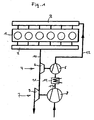
- a supercharged internal combustion engine 1 is shown, with which the outlet channels the cylinder related exhaust manifold with 2 and its with the intake ports the cylinder related charge air manifold is designated 3.
- the Internal combustion engine 1 is associated with a 2-stage turbocharger whose high-pressure stage 4 is a compressor 5 driving turbine 6 and its low pressure stage 7 a Compressor 8 driving turbine 9 has.
- the turbine 6 of the high-pressure stage 4 is via an exhaust passage 10 with the exhaust manifold 2 and via a connecting channel 11 with the turbine 9 of the low pressure stage 7 in conjunction.
- the compressor 5 of the high-pressure stage 4 is a charge air line 12 with the charge air manifold 3 and over a connecting line 13 to the compressor 8 of the low-pressure stage 7 in conjunction.
- In the connecting line 13 is given a charge air cooler 14.
- This intercooler 14 is according to the invention and as further described below.
- the charge air cooler 14 can be flowed through by a cooling medium Cooling insert 15 - see Fig. 2 - in the charge air conducting connecting channel 13 and a specially designed portion 16 of the connecting channel 13 - see Fig. 3, 4 - formed, wherein the connecting channel 13 in this section 16 with its wall 17, the outer wall of the Intercooler 14 forms and by appropriate shape design for an acceptable Cooling of the built-in cooling insert 15 - see Fig. 5 - flowing around Charge air through the cooling medium flowing through the cooling medium 15 sufficient air flow volume limited.
- the cooling insert 15 is in the manner of a preassembled cartridge educated.
- This cooling insert 15 consists of a base plate 18 and a plurality, for. B. three, outside with a plurality of cooling fins - see Fig. 6 - provided cooling tubes 19, 20, 21.
- each cooling tube 19, 20, 21 at its one end a circular cylindrical Covenant 22, with which it is perpendicular to the base plate 18 in a blind hole 23rd installed the same, z. B. pressed, welded or soldered.
- At his other End carries each cooling tube 19, 20, 21 on a circular cylindrical collar 24 a sealing sleeve 25.
- Within the cooling insert 15 communicates each cooling tube 19, 20, 21 with his Inner bore 26 with a formed in the base plate 18 distribution channel 27th
- the connecting channel 13 is in that, the part of the charge air cooler 14 forming section 16 from a substantially straight cooling tube region 16 and two, each one End region in front of the axial end 28, 29 laterally outgoing manifolds 30, 31.
- a cartridge cooling insert 15 in its final assembly by the an open end 28 of the straight portion 16 of the connecting line 13 in the interior thereof einschiebbar, where he with the sealing sleeves 25 on the cooling tubes 19, 20, 21 in on the opposite Holding holes 32 formed in the axial end 29 of the section 16 sealing immersed and finally leak-free with its base plate 18 at one axial end 28 is fastened by means of several screws 33.
- the cooling insert according to the invention 15 has three parallel in one Level with a small distance next to each other, the same length and the same design Cooling tubes 19, 20, 21 - see Fig. 6 -, of which two (20, 21) parallel in one Direction - see arrow 39 in Fig. 5 - are flowed through with cooling medium and the third cooling tube 19 in the other direction - see arrow 40 - is flowed through by cooling medium and virtually forms a coolant internal cooling medium return line.
- the connecting channel 13 surrounds in its straight channel section 16 with its wall 17th the built-in cooling insert 15 with a certain, not too large distance, the smaller as the outer diameter of the cooling tubes 19, 20, 21 is.
Abstract
Description
Die Erfindung betrifft eine Brennkraftmaschine mit 2-stufigem Abgasturbolader und mit einem Ladeluftkühler in der Verbindungsleitung zwischen dem Verdichter der Niederdruckstufe und dem Verdichter der Hochdruckstufe.The invention relates to an internal combustion engine with 2-stage exhaust gas turbocharger and with a Intercooler in the connecting line between the compressor of the low pressure stage and the compressor of the high-pressure stage.
Eine Brennkraftmaschine mit solchen Merkmalen ist z. B. aus der DE 19961610 A1 bekannt. Dabei ist zwar ein Ladeluftkühler in der Verbindungsleitung zwischen dem Verdichter der Niederdruckstufe und jenem der Hochdruckstufe vorgesehen, es bleibt jedoch offen, wie dieser Ladeluftkühler ausgebildet ist.An internal combustion engine with such features is z. B. from DE 19961610 A1. Although it is a charge air cooler in the connecting line between the compressor of Low-pressure stage and that of the high-pressure stage provided, it remains open, however this intercooler is formed.
Es ist daher Aufgabe der Erfindung, einen Ladeluftkühler zu schaffen, der den räumlich beengten Verhältnissen an der Brennkraftmaschine zwischen Nieder- und Hochdruckverdichter Rechnung trägt.It is therefore an object of the invention to provide a charge air cooler, the space cramped Conditions of the internal combustion engine between low and high pressure compressor Takes into account.
Diese Aufgabe ist bei einer Brennkraftmaschine der gattungsgemäßen Art erfindungsgemäß durch einen Ladeluftkühler der im Kennzeichen des Anspruchs 1 angegebenen Art gelöst.This object is according to the invention in an internal combustion engine of the generic type solved by a charge air cooler specified in the characterizing part of claim 1. Art.
Vorteilhafte Ausgestaltungen der erfindungsgemäßen Lösung sind in den Unteransprüchen gekennzeichnet.Advantageous embodiments of the solution according to the invention are in the subclaims characterized.
Der erfindungsgemäße Ladeluftkühler zeichnet sich durch extrem kleine, aber trotzdem wirksame Bauweise aus. Dadurch, dass der Kühleinsatz nach Art einer Kartusche in einen speziell gestalteten Abschnitt der Verbindungsleitung zwischen ATL-Niederdruckverdichter und ATL-Hochdruckverdichter einbaubar ist und dieser Abschnitt der Verbindungsleitung mit seiner Wand die Außenwand des Ladeluftkühlers bildet, ist einerseits eine einfache Herstellung dieser Bauteile und andererseits auch einfache Montage derselben zwischen den beiden ATL-Stufen möglich. Eine hinreichend große Kühlwirkung wird deshalb erzielt, weil die Kühlrohre außen mit einer Vielzahl von Kühlrippen versehen sind, die für entsprechenden Wärmetausch sorgen.The intercooler according to the invention is characterized by extremely small, yet effective Construction. Characterized in that the cooling insert in the manner of a cartridge in a special designed section of the connecting line between ATL low-pressure compressor and ATL high-pressure compressor is installable and this section of the connecting pipe with his Wall forms the outer wall of the intercooler, on the one hand, a simple production these components and on the other hand also easy installation of the same between the two ATL levels possible. A sufficiently large cooling effect is achieved because the cooling tubes are provided externally with a plurality of cooling fins, which are suitable for heat exchange to care.
Nachstehend ist der erfindungsgemäße Ladeluftkühler anhand eines in der Zeichnung dargestellten Ausführungsbeispiels noch näher erläutert. In der Zeichnung zeigen:
- Fig. 1
- eine Prinzipdarstellung einer Brennkraftmaschine mit 2-stufiger Aufladung und Ladeluftkühlung zwischen Niederdruck- und Hochdruckstufe,
- Fig. 2
- ein Ausführungsbeispiel für einen erfindungsgemäßen Kühleinsatz im Schnitt,
- Fig. 3
- einen zum Ausführungsbeispiel gemäß Fig. 2 gehörenden Deckel,
- Fig. 4
- ein Ausführungsbeispiel eines Verbindungsleitungsabschnitts zwischen den Verdichtern der beiden ATL-Stufen als Teil des erfindungsgemäßen Ladeluftkühlers,
- Fig. 5
- ein Ausführungsbeispiel des erfindungsgemäßen Ladeluftkühlers unter Verwendung des Kühleinsatzes gemäß Fig. 2, des Deckels gemäß Fig. 3 und des Verbindungsleitungsabschnitts gemäß Fig. 4,
- Fig. 6
- einen Querschnitt durch die Darstellung von Fig. 5 entlang der dortigen Schnittlinie VI-VI.
- Fig. 1
- a schematic diagram of an internal combustion engine with 2-stage charging and charge air cooling between low pressure and high pressure stage,
- Fig. 2
- an embodiment of a cooling insert according to the invention in section,
- Fig. 3
- a cover belonging to the embodiment according to FIG. 2,
- Fig. 4
- an embodiment of a connecting line section between the compressors of the two ATL stages as part of the charge air cooler according to the invention,
- Fig. 5
- an embodiment of the charge air cooler according to the invention using the cooling insert according to FIG. 2, the cover according to FIG. 3 and the connecting line section according to FIG. 4,
- Fig. 6
- a cross-section through the representation of Fig. 5 along the section line VI-VI.
In Fig. 1 ist eine aufgeladene Brennkraftmaschine 1 gezeigt, deren mit den Auslasskanälen
der Zylinder in Verbindung stehende Abgassammelleitung mit 2 und deren mit den Einlasskanälen
der Zylinder in Verbindung stehende Ladeluftsammelleitung mit 3 bezeichnet ist. Der
Brennkraftmaschine 1 ist ein 2-stufiger Abgasturbolader zugeordnet, dessen Hochdruckstufe
4 eine einen Verdichter 5 antreibende Turbine 6 und dessen Niederdruckstufe 7 eine einen
Verdichter 8 antreibende Turbine 9 aufweist. Die Turbine 6 der Hochdruckstufe 4 steht
über einen Abgaskanal 10 mit der Abgassammelleitung 2 und über einen Verbindungskanal
11 mit der Turbine 9 der Niederdruckstufe 7 in Verbindung. Der Verdichter 5 der Hochdruckstufe
4 steht über eine Ladeluftleitung 12 mit der Ladeluftsammelleitung 3 und über
eine Verbindungsleitung 13 mit dem Verdichter 8 der Niederdruckstufe 7 in Verbindung. In
der Verbindungsleitung 13 ist ein Ladeluftkühler 14 gegeben. Dieser Ladeluftkühler 14 ist
entsprechend der Erfindung und wie nachfolgend des weiteren beschrieben ausgebildet.In Fig. 1, a supercharged internal combustion engine 1 is shown, with which the outlet channels
the cylinder related exhaust manifold with 2 and its with the intake ports
the cylinder related charge air manifold is designated 3. Of the
Internal combustion engine 1 is associated with a 2-stage turbocharger whose high-
Erfindungsgemäß ist der Ladeluftkühler 14 durch einen von einem Kühlmedium durchströmbaren
Kühleinsatz 15 - siehe Fig. 2 - im ladeluftführenden Verbindungskanal 13 und einen
speziell gestalteten Abschnitt 16 des Verbindungskanals 13 - siehe Fig. 3, 4 - gebildet, wobei
der Verbindungskanal 13 in diesem Abschnitt 16 mit seiner Wand 17 die Außenwand des
Ladeluftkühlers 14 bildet und durch entsprechende formmäßige Gestaltung ein für eine akzeptable
Kühlung der den darin eingebauten Kühleinsatz 15 - siehe Fig. 5 - umströmenden
Ladeluft durch das den Kühleinsatz 15 durchströmende Kühlmedium ausreichendes Luftdurchsatzvolumen
begrenzt. According to the invention, the
Wie gut aus Fig. 2 ersichtlich, ist der Kühleinsatz 15 nach Art einer vormontierten Kartusche
ausgebildet. Dieser Kühleinsatz 15 besteht aus einer Grundplatte 18 und mehreren, z. B.
drei, außen mit einer Vielzahl von Kühlrippen - siehe Fig. 6 - versehenen Kühlrohren 19, 20,
21. Dabei weist jedes Kühlrohr 19, 20, 21 an seinem einen Ende einen kreiszylindrischen
Bund 22 auf, mit dem es senkrecht stehend zur Grundplatte 18 in eine Sacklochbohrung 23
derselben eingebaut, z. B. eingepresst, eingeschweißt oder eingelötet ist. An seinem anderen
Ende trägt jedes Kühlrohr 19, 20, 21 auf einem kreiszylindrischen Bund 24 eine Dichthülse
25. Innerhalb des Kühleinsatzes 15 kommuniziert jedes Kühlrohr 19, 20, 21 mit seiner
Innenbohrung 26 mit einem in der Grundplatte 18 ausgebildeten Verteilerkanal 27.As can readily be seen in FIG. 2, the
Der Verbindungskanal 13 besteht in jenem, den Teil des Ladeluftkühlers 14 bildenden Abschnitt
16 aus einem weitgehend geraden Kühlrohrbereich 16 und zwei, an jeweils einem
Endbereich vor dem axialen Ende 28, 29 seitlich abgehenden Krümmern 30, 31. Dabei ist
der nach Art einer Kartusche ausgebildete Kühleinsatz 15 bei seiner Endmontage durch das
eine offene Ende 28 des geraden Abschnitts 16 der Verbindungsleitung 13 in dessen Innenraum
einschiebbar, wobei er mit den Dichthülsen 25 an den Kühlrohren 19, 20, 21 in am gegenüberliegenden
axialen Ende 29 des Abschnitts 16 ausgebildete Haltebohrungen 32
dichtend eintaucht und zuletzt mit seiner Grundplatte 18 am einen axialen Ende 28 leckagefrei
mittels mehrerer Schrauben 33 befestigt wird. Zuletzt wird der gerade Abschnitt 16 des
Verbindungskanals 13 an seinem den Dichthülsen 25 benachbarten Ende 29 durch einen
dort befestigbaren Deckel 34 verschlossen. Dieser Deckel 34 weist intern einen von außen
her - siehe Pfeil 35 - mit Kühlmedium versorgbaren Verteilerkanal 36 auf, mit dem ein Teil
der Kühlrohre, hier die Kühlrohre 20, 21 kommuniziert. Außerdem weist der Deckel 34 intern
einen mit einer externen Kühlmedium-Rücklaufleitung - angedeutet durch Pfeil 37 - verbundenen
Rücklaufkanal 38 auf, mit dem das oder die übrigen Kühlrohr(e), hier das Kühlrohr 19,
kommuniziert.The connecting
Im dargestellten Beispiel weist der erfindungsgemäße Kühleinsatz 15 drei parallel in einer
Ebene mit geringen Abstand nebeneinander angeordnete, gleich lange und gleich ausgebildete
Kühlrohre 19, 20, 21 auf - siehe Fig. 6 -, wovon zwei (20, 21) parallel in der einen
Richtung - siehe Pfeil 39 in Fig. 5 - mit Kühlmedium durchströmt sind und das dritte Kühlrohr
19 in der anderen Richtung - siehe Pfeil 40 - von Kühlmedium durchströmt wird und
quasi eine kühleinsatzinterne Kühlmedium-Rückleitung bildet. In the example shown, the cooling insert according to the
Der Verbindungskanal 13 umgibt in seinem geraden Kanalabschnitt 16 mit seiner Wand 17
den eingebauten Kühleinsatz 15 mit einem gewissen, nicht zu großen Abstand, der kleiner
als der Außendurchmesser der Kühlrohre 19, 20, 21 ist.The connecting
In diesem erfindungsgemäßen Ladeluftkühler 14 wird trotz seiner relativ kleinen Baugröße
aufgrund der intensiven Durchströmung der Kühlrohre 19, 20, 21 mit Kühlmedium und des
innigen Kontakts der den Kühleinsatz 15 im Verbindungskanal-Abschnitt 16 durchströmenden
Ladeluft mit den Kühlrippen der Kühlrohre 19, 20, 21 eine hinreichende Kühlwirkung
erzielt.In this
Claims (5)
Priority Applications (1)
| Application Number | Priority Date | Filing Date | Title |
|---|---|---|---|
| PL04016516T PL1505274T3 (en) | 2003-08-05 | 2004-07-14 | Internal combustion engine with two-stage turbocharging and charge air cooling between low and high pressure compressors |
Applications Claiming Priority (2)
| Application Number | Priority Date | Filing Date | Title |
|---|---|---|---|
| AT12382003 | 2003-08-05 | ||
| AT0123803A AT414155B (en) | 2003-08-05 | 2003-08-05 | INTERNAL COMBUSTION ENGINE WITH 2-STAGE ABGASTURBOLADER AND CHARGE AIR COOLING BETWEEN LOW AND HIGH PRESSURE COMPRESSORS |
Publications (2)
| Publication Number | Publication Date |
|---|---|
| EP1505274A1 true EP1505274A1 (en) | 2005-02-09 |
| EP1505274B1 EP1505274B1 (en) | 2012-06-20 |
Family
ID=33545804
Family Applications (1)
| Application Number | Title | Priority Date | Filing Date |
|---|---|---|---|
| EP04016516A Active EP1505274B1 (en) | 2003-08-05 | 2004-07-14 | Internal combustion engine with two-stage turbocharging and charge air cooling between low and high pressure compressors |
Country Status (5)
| Country | Link |
|---|---|
| EP (1) | EP1505274B1 (en) |
| CN (1) | CN1311147C (en) |
| AT (1) | AT414155B (en) |
| PL (1) | PL1505274T3 (en) |
| RU (1) | RU2273744C1 (en) |
Cited By (3)
| Publication number | Priority date | Publication date | Assignee | Title |
|---|---|---|---|---|
| WO2008104402A1 (en) * | 2007-02-28 | 2008-09-04 | Behr Gmbh & Co.Kg | Charge-air cooling device, system for turbocharging and/or charge-air cooling, method for charge-air cooling |
| DE102007010123A1 (en) | 2007-02-28 | 2008-09-04 | Behr Gmbh & Co. Kg | Charge-cooling device for a motor vehicle's internal combustion engine has heat-exchangers for high-pressure and low-pressure charge cooling with a coolant feed and coolant drain line |
| EP1995463A2 (en) | 2007-05-24 | 2008-11-26 | Behr GmbH & Co. KG | Multi stage compressor unit with cooling device |
Families Citing this family (5)
| Publication number | Priority date | Publication date | Assignee | Title |
|---|---|---|---|---|
| DE102010007601A1 (en) * | 2010-02-11 | 2011-08-11 | MTU Friedrichshafen GmbH, 88045 | Charged internal combustion engine |
| DE102011002554A1 (en) * | 2011-01-12 | 2012-07-12 | Ford Global Technologies, Llc | Internal combustion engine with cylinder head and turbine |
| DE102011003906A1 (en) | 2011-02-10 | 2012-08-16 | Continental Automotive Gmbh | Exhaust gas turbocharger with cooled turbine housing and reduced pressure loss |
| DE102011075617B4 (en) * | 2011-05-10 | 2013-05-08 | Mtu Friedrichshafen Gmbh | A method for guiding a charge air, terminal box for a radiator assembly and radiator assembly for an internal combustion engine and internal combustion engine with a two-stage supercharging |
| JP5903917B2 (en) * | 2012-02-08 | 2016-04-13 | トヨタ自動車株式会社 | Cooling device for internal combustion engine |
Citations (4)
| Publication number | Priority date | Publication date | Assignee | Title |
|---|---|---|---|---|
| DE1626007A1 (en) * | 1968-03-05 | 1970-10-01 | Heinrich Habermann Fa | Charge air cooler for diesel engines |
| JPS60101223A (en) * | 1983-11-08 | 1985-06-05 | Yanmar Diesel Engine Co Ltd | Two-stage supercharging type internal-combustion engine |
| US4688383A (en) * | 1984-06-04 | 1987-08-25 | Juan Targa Pascual | Supercharger system for use with heat engines |
| DE19961610A1 (en) * | 1999-12-21 | 2001-04-05 | Daimler Chrysler Ag | Internal combustion engine with two exhaust gas turbochargers for motor vehicle, has control unit that increases/decreases variable geometry turbine cross-section for high/low engine speed |
Family Cites Families (4)
| Publication number | Priority date | Publication date | Assignee | Title |
|---|---|---|---|---|
| EP0874142B1 (en) * | 1997-04-24 | 2002-11-20 | Volkswagen Aktiengesellschaft | Device for integrated guiding of liquid and gaseous media |
| JP4512873B2 (en) * | 2001-04-10 | 2010-07-28 | 本田技研工業株式会社 | Intercooler |
| DE10141490A1 (en) * | 2001-08-24 | 2003-03-13 | Behr Gmbh & Co | Radiator and method for cooling a medium |
| FI116802B (en) * | 2002-01-17 | 2006-02-28 | Waertsilae Finland Oy | Suction air arrangement for piston engine |
-
2003
- 2003-08-05 AT AT0123803A patent/AT414155B/en not_active IP Right Cessation
-
2004
- 2004-07-14 EP EP04016516A patent/EP1505274B1/en active Active
- 2004-07-14 PL PL04016516T patent/PL1505274T3/en unknown
- 2004-08-04 RU RU2004123922/06A patent/RU2273744C1/en active
- 2004-08-05 CN CNB2004100560298A patent/CN1311147C/en active Active
Patent Citations (4)
| Publication number | Priority date | Publication date | Assignee | Title |
|---|---|---|---|---|
| DE1626007A1 (en) * | 1968-03-05 | 1970-10-01 | Heinrich Habermann Fa | Charge air cooler for diesel engines |
| JPS60101223A (en) * | 1983-11-08 | 1985-06-05 | Yanmar Diesel Engine Co Ltd | Two-stage supercharging type internal-combustion engine |
| US4688383A (en) * | 1984-06-04 | 1987-08-25 | Juan Targa Pascual | Supercharger system for use with heat engines |
| DE19961610A1 (en) * | 1999-12-21 | 2001-04-05 | Daimler Chrysler Ag | Internal combustion engine with two exhaust gas turbochargers for motor vehicle, has control unit that increases/decreases variable geometry turbine cross-section for high/low engine speed |
Non-Patent Citations (1)
| Title |
|---|
| PATENT ABSTRACTS OF JAPAN vol. 0092, no. 49 (M - 419) 5 October 1985 (1985-10-05) * |
Cited By (8)
| Publication number | Priority date | Publication date | Assignee | Title |
|---|---|---|---|---|
| WO2008104402A1 (en) * | 2007-02-28 | 2008-09-04 | Behr Gmbh & Co.Kg | Charge-air cooling device, system for turbocharging and/or charge-air cooling, method for charge-air cooling |
| DE102007010123A1 (en) | 2007-02-28 | 2008-09-04 | Behr Gmbh & Co. Kg | Charge-cooling device for a motor vehicle's internal combustion engine has heat-exchangers for high-pressure and low-pressure charge cooling with a coolant feed and coolant drain line |
| WO2008104373A1 (en) * | 2007-02-28 | 2008-09-04 | Behr Gmbh & Co. Kg | Charge-air cooling device, system for turbocharging and/or charge-air cooling, method for charge-air cooling |
| CN101641502A (en) * | 2007-02-28 | 2010-02-03 | 贝洱两合公司 | The device that is used for the pressurized air cooling is used for the system that turbosupercharging and/or pressurized air cool off, the method for pressurized air cooling |
| EP1995463A2 (en) | 2007-05-24 | 2008-11-26 | Behr GmbH & Co. KG | Multi stage compressor unit with cooling device |
| DE102007024633A1 (en) | 2007-05-24 | 2008-11-27 | Behr Gmbh & Co. Kg | Multi-stage compressor unit with cooling device |
| EP1995463A3 (en) * | 2007-05-24 | 2011-06-01 | Behr GmbH & Co. KG | Multi stage compressor unit with cooling device |
| US8459961B2 (en) | 2007-05-24 | 2013-06-11 | Behr Gmbh & Co. Kg | Multistage compressor unit with cooling device |
Also Published As
| Publication number | Publication date |
|---|---|
| CN1311147C (en) | 2007-04-18 |
| RU2004123922A (en) | 2006-01-27 |
| CN1580514A (en) | 2005-02-16 |
| AT414155B (en) | 2006-09-15 |
| ATA12382003A (en) | 2005-12-15 |
| PL1505274T3 (en) | 2012-11-30 |
| EP1505274B1 (en) | 2012-06-20 |
| RU2273744C1 (en) | 2006-04-10 |
Similar Documents
| Publication | Publication Date | Title |
|---|---|---|
| DE19853455B4 (en) | Radiator arrangement for a supercharged internal combustion engine with exhaust gas recirculation | |
| DE102009026482A1 (en) | Inlet device of an internal combustion engine and internal combustion engine | |
| DE60015374T2 (en) | SPIRAL HEAT EXCHANGE | |
| DE102006000337A1 (en) | Air intake device | |
| DE102007035556A1 (en) | Mixing apparatus for adding exhaust gas recirculation flow into charge air flow of internal-combustion engine, has connecting tube running transverse through passage channel and connecting inlet opening with one of chambers | |
| DE102005005190A1 (en) | Exhaust cooler assembly for a motor vehicle | |
| DE102017104619A1 (en) | EXHAUST RECYCLING FACILITY | |
| DE2828557A1 (en) | INTERCOOLER FOR COMBUSTION ENGINES | |
| DE112013005023T5 (en) | Turbulence inducing bearing housing spacers and core | |
| DE112016004891T5 (en) | exhaust gas cooler | |
| EP2037201A2 (en) | Charge air module for a combustion engine | |
| EP1505274A1 (en) | Internal combustion engine with two-stage turbocharging and charge air cooling between low and high pressure compressors | |
| DE19546545B4 (en) | intake manifold | |
| DE102008014328B4 (en) | Suction muffler for a hermetically sealed refrigerant compressor | |
| DE10239132A1 (en) | exhaust silencer | |
| AT523182B1 (en) | COMBUSTION ENGINE WITH ONE INLET TRAIN | |
| DE19858771C2 (en) | Internal combustion engine with several cylinders | |
| DE10347693A1 (en) | Reduction of NVH (noise, vibrations, hardness) and gas pulsation in an air conditioning compressor | |
| EP0819837A1 (en) | Cooling circuit of an internal combustion engine | |
| DE102004045661B4 (en) | Device for cooling the charge air in a supercharged internal combustion engine | |
| DE102014018035A1 (en) | Air line for an intake tract of an internal combustion engine | |
| DE10045636A1 (en) | Secondary gas directing device, has channel integrated with wall section of collecting area, the channel communicating at one end with connecting piece and with inlet openings at the other | |
| DE2740465A1 (en) | IC engine with recirculated exhaust - has duct extending between inlet and exhaust passages of cylinder head consisting of drilling or inserted pipe | |
| DE102017204843B3 (en) | High-pressure fuel-plug-in pump for a fuel injection system | |
| DE102008018668A1 (en) | Exhaust gas manifold for internal combustion engine, has four cylinder connection pieces, where two of cylinder connection pieces are formed by half shells and remaining connection pieces are formed by another two half shells |
Legal Events
| Date | Code | Title | Description |
|---|---|---|---|
| PUAI | Public reference made under article 153(3) epc to a published international application that has entered the european phase |
Free format text: ORIGINAL CODE: 0009012 |
|
| AK | Designated contracting states |
Kind code of ref document: A1 Designated state(s): AT BE BG CH CY CZ DE DK EE ES FI FR GB GR HU IE IT LI LU MC NL PL PT RO SE SI SK TR |
|
| AX | Request for extension of the european patent |
Extension state: AL HR LT LV MK |
|
| 17P | Request for examination filed |
Effective date: 20050121 |
|
| RAP1 | Party data changed (applicant data changed or rights of an application transferred) |
Owner name: MAN NUTZFAHRZEUGE OESTERREICH AG |
|
| AKX | Designation fees paid |
Designated state(s): DE FR IT PL SE TR |
|
| 17Q | First examination report despatched |
Effective date: 20061109 |
|
| GRAP | Despatch of communication of intention to grant a patent |
Free format text: ORIGINAL CODE: EPIDOSNIGR1 |
|
| RAP1 | Party data changed (applicant data changed or rights of an application transferred) |
Owner name: MAN TRUCK & BUS OESTERREICH AG |
|
| GRAS | Grant fee paid |
Free format text: ORIGINAL CODE: EPIDOSNIGR3 |
|
| GRAA | (expected) grant |
Free format text: ORIGINAL CODE: 0009210 |
|
| AK | Designated contracting states |
Kind code of ref document: B1 Designated state(s): DE FR IT PL SE TR |
|
| REG | Reference to a national code |
Ref country code: DE Ref legal event code: R096 Ref document number: 502004013590 Country of ref document: DE Effective date: 20120809 |
|
| REG | Reference to a national code |
Ref country code: SE Ref legal event code: TRGR |
|
| REG | Reference to a national code |
Ref country code: PL Ref legal event code: T3 |
|
| PLBE | No opposition filed within time limit |
Free format text: ORIGINAL CODE: 0009261 |
|
| STAA | Information on the status of an ep patent application or granted ep patent |
Free format text: STATUS: NO OPPOSITION FILED WITHIN TIME LIMIT |
|
| 26N | No opposition filed |
Effective date: 20130321 |
|
| REG | Reference to a national code |
Ref country code: DE Ref legal event code: R097 Ref document number: 502004013590 Country of ref document: DE Effective date: 20130321 |
|
| REG | Reference to a national code |
Ref country code: FR Ref legal event code: PLFP Year of fee payment: 13 |
|
| REG | Reference to a national code |
Ref country code: FR Ref legal event code: PLFP Year of fee payment: 14 |
|
| REG | Reference to a national code |
Ref country code: FR Ref legal event code: PLFP Year of fee payment: 15 |
|
| REG | Reference to a national code |
Ref country code: DE Ref legal event code: R081 Ref document number: 502004013590 Country of ref document: DE Owner name: MAN TRUCK & BUS SE, DE Free format text: FORMER OWNER: MAN TRUCK & BUS OESTERREICH AG, STEYR, AT |
|
| PGFP | Annual fee paid to national office [announced via postgrant information from national office to epo] |
Ref country code: SE Payment date: 20230317 Year of fee payment: 20 |
|
| PGFP | Annual fee paid to national office [announced via postgrant information from national office to epo] |
Ref country code: TR Payment date: 20230703 Year of fee payment: 20 Ref country code: IT Payment date: 20230721 Year of fee payment: 20 |
|
| PGFP | Annual fee paid to national office [announced via postgrant information from national office to epo] |
Ref country code: PL Payment date: 20230703 Year of fee payment: 20 Ref country code: FR Payment date: 20230725 Year of fee payment: 20 Ref country code: DE Payment date: 20230726 Year of fee payment: 20 |