EP1504983B1 - Vehicle subframe - Google Patents
Vehicle subframe Download PDFInfo
- Publication number
- EP1504983B1 EP1504983B1 EP20030102483 EP03102483A EP1504983B1 EP 1504983 B1 EP1504983 B1 EP 1504983B1 EP 20030102483 EP20030102483 EP 20030102483 EP 03102483 A EP03102483 A EP 03102483A EP 1504983 B1 EP1504983 B1 EP 1504983B1
- Authority
- EP
- European Patent Office
- Prior art keywords
- subframe
- extruded
- aluminum profile
- chambers
- embodied
- Prior art date
- Legal status (The legal status is an assumption and is not a legal conclusion. Google has not performed a legal analysis and makes no representation as to the accuracy of the status listed.)
- Expired - Fee Related
Links
Images
Classifications
-
- B—PERFORMING OPERATIONS; TRANSPORTING
- B62—LAND VEHICLES FOR TRAVELLING OTHERWISE THAN ON RAILS
- B62D—MOTOR VEHICLES; TRAILERS
- B62D3/00—Steering gears
- B62D3/02—Steering gears mechanical
- B62D3/12—Steering gears mechanical of rack-and-pinion type
-
- B—PERFORMING OPERATIONS; TRANSPORTING
- B62—LAND VEHICLES FOR TRAVELLING OTHERWISE THAN ON RAILS
- B62D—MOTOR VEHICLES; TRAILERS
- B62D21/00—Understructures, i.e. chassis frame on which a vehicle body may be mounted
- B62D21/11—Understructures, i.e. chassis frame on which a vehicle body may be mounted with resilient means for suspension, e.g. of wheels or engine; sub-frames for mounting engine or suspensions
-
- B—PERFORMING OPERATIONS; TRANSPORTING
- B62—LAND VEHICLES FOR TRAVELLING OTHERWISE THAN ON RAILS
- B62D—MOTOR VEHICLES; TRAILERS
- B62D29/00—Superstructures, understructures, or sub-units thereof, characterised by the material thereof
- B62D29/008—Superstructures, understructures, or sub-units thereof, characterised by the material thereof predominantly of light alloys, e.g. extruded
Definitions
- the invention relates to a motor vehicle with a subframe for receiving suspension components to connect the suspension components to a vehicle body, wherein the subframe is formed as an extruded aluminum profile which is extruded in a horizontal direction.
- Such subframes are known. These are used in passenger cars for connecting suspension components to the vehicle body. To ensure that the car z. B. has a good dynamic performance in extreme maneuvers, the subframe must have sufficient rigidity and strength.
- the known subframe made of steel, z. B. made of molded metal sheets, pipes or castings.
- the subframe can be connected with or without a rubber mount to the vehicle body.
- these subframes made in this way are very heavy.
- the suspension components are made of aluminum. This can z. B. wishbones, steering sticks or damper rods, which are attached to the subframe.
- Aluminum is expensive compared to steel. Currently, the differences from aluminum to steel are approximately five times the material price or approximately three times the production price of the subframe according to the invention over the prior art.
- a further disadvantage is that in comparison to steel low density of aluminum in terms of a tool design and a higher wear of the tool due to the adhesion of the steel tool and the aluminum sheet and because of the lower compared to steel formability of the sheet material made of aluminum must be considered.
- the EP 1 270 374 A2 which is based on the preamble of claim 1, relates to a cross member of a motor vehicle suspension with a central body and two separate side elements.
- the central body is extruded.
- a subframe with a light metal cast housing of a rack and pinion steering and arranged thereon console-like lateral mounting arms with bearings for releasable arrangement on a vehicle body and support arms with bearings for the pivotable articulation of Rad Equipmentslenkern is disclosed in EP 0 779 204 A1.
- the subframe is designed as an assembly module for units and / or unit parts and as an assembly module with defined connection points of the units and / or unit parts.
- the invention has for its object to provide an improved subframe available, which is much easier and cheaper to manufacture.
- the subframe has a steering housing, wherein the subframe is formed integrally with the steering housing, and wherein the aluminum profile is formed as a rectangular hollow body with chambers which are open at the front, and wherein the aluminum profile on a broad side wall a closed Has elevation with a substantially cylindrical channel, which form the steering housing.
- the invention is based on the finding that aluminum can be relatively easily and inexpensively bring in arbitrarily complicated profile shapes by extrusion in contrast to steel. Extrusion is thus an alternative production variant for subframe. Here, only one device is required to produce a base part by extrusion. In order to obtain lightweight subframes, the base part can be conveniently cut by means of cutting devices in subframe with the desired dimensions. This is also beneficial because it achieves a reproducible manufacturing process that significantly reduces costs. Another advantage here is that aluminum is much more resistant to corrosion than steel.
- the steering housing is made in one piece with the subframe. As a result, a further, significant weight and cost reduction is achieved.
- Figure 1 shows an auxiliary frame 1, which is formed as an extruded aluminum profile 2.
- the aluminum profile 2 is preferably extruded in a vertical direction. The vertical direction is defined here from top to bottom or from bottom to top.
- the aluminum profile 2 is substantially square with transverse struts 3 and perpendicular thereto arranged longitudinal struts 4.
- the longitudinal struts 4 and cross struts 3 comprise an opening 6 of the subframe 1.
- the longitudinal struts 4 widen in each case by a cross strut 3 to cross strut opposite thereto 3.
- the aluminum profile 2 is rounded, with internal transitions from the cross struts 3 to the Longitudinal struts 4 are rounded within the opening 6.
- On the outside 7 bearing ears 8 are arranged at the corners.
- the bearing tubes 8 each have round through holes 9.
- suitable fasteners can be added, with which the subframe 1 can be connected to the vehicle body.
- the fastening means may be accommodated in rubber bearings or the like, which are adapted to the through holes 9. This can disk-shaped rubber bearings abut the edges of the through holes 9, or preferably rubber bearings are inserted with a through hole in the through holes 9.
- the recesses 11 have different geometric configurations, wherein the recesses 11 in the transverse struts 3 are preferably designed in each case rectangular.
- Each diametrically opposite to a central axis Y-Y recesses 11 in the longitudinal struts 4 also each have a similar configuration.
- the subframe 1 shown in FIG. 1 is a so-called perimeter frame, which can preferably be used for larger middle class passenger cars.
- Figure 2 shows a second embodiment of the subframe 1, which is formed as an extruded aluminum profile 2, but with the difference that the subframe 1 is made in the illustrated embodiment as a solid body 12.
- the solid body 12 has at its corners 13 bearing tubes 14 with substantially triangular through holes 16.
- the through-holes 16 can also be designed to be round, similar to that described for FIG.
- An attachment of the subframe 1 and in particular the measures for vibration isolation are similar to that described for Figure 1.
- the solid body 12 preferably has systematically introduced triangular recesses 11.
- the subframe 1 shown in Figure 2 may preferably be used in small cars.
- Both the recesses 11 and the through holes 9 and 16 are respectively introduced during the production of the subframe 1 during extrusion, so that the subframe 1 is reduced in weight in addition to the weight loss that can be achieved by the inventive design by means of the extruded aluminum profile 2 ,
- the respective recesses 11 and through-holes 9 and 16 should be designed such that the strength properties of the aluminum profile 2 are not reduced.
- the recesses 11 and through holes 9 and 16 can of course also be incorporated into the subframe 1 after extrusion.
- Figure 3 shows a third embodiment of a subframe 1, which is formed as an extruded aluminum profile 2.
- the aluminum profile 2 is extruded in a horizontal direction.
- the horizontal direction is here as the direction from right to left, from left to right or from the front defined backwards or from back to front.
- the aluminum profile 2 is formed as a rectangular plate 17 with broad sides 18 and vertical longitudinal sides 19 thereto.
- chambers 21 are introduced.
- the chambers 21 extend parallel to the broad sides 18 and each parallel to each other continuously from a longitudinal end face 22 to a longitudinal side opposite thereto. Laterally adjacent chambers 21 are separated by means of continuous webs 23.
- the aluminum profile 2 in each case parallel to the chambers 21 extending receiving devices 24.
- the receiving devices 24 are each open at the broad sides 18, so that the receiving device 24 has top and bottom flanges 26. In the upper and lower side flanges 26 each congruent bores 27 are introduced.
- a wishbone can be received by the receiving device 24, which is fastened by means of suitable fastening devices which are guided through the bores 27.
- suitable fastening devices which are guided through the bores 27.
- For vibration isolation of the wishbone disc-shaped rubber bearings may have, each bear against a side facing the wishbone of the respective flange 26 and on the wishbone.
- the fastening means 28 are inserted with a mounting end 29 in holes 31 and by means of material connection, z. B. welding connected to the subframe 1.
- the fastening means 28 project from the auxiliary frame 1 and, in the exemplary embodiment shown, extend slightly from the fastening end 29 in the direction of the broad side 18.
- the fastening means 28 have a hammer-head-shaped extension 33.
- the fastening means 28 may be made of solid material or preferably hollow bodies such. B. pipes exist.
- the hammerhead-shaped extension 33 is suitable as a hollow body for receiving bolts, with which a connection to the vehicle body can be produced. For vibration isolation of the hammerhead-shaped extension 33 may have rubber bearings in which the bolts are mounted.
- the fastening means 28 may also have other configurations than the exemplary embodiment illustrated in FIG.
- auxiliary frame 1 z. B. could be configured bone.
- the subframe 1 described in FIGS. 1 to 3 are in each case cut as an extruded aluminum profile 2 from a base part which is continuously extruded by means of a suitable cutting device to the required dimensions.
- the extruded aluminum 2 may also be composed of extruded individual parts, wherein preferably a cohesive connection, such. B. is applied by welding.
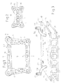
- FIG. 4 shows an auxiliary frame 1, which has a steering housing 35, wherein the auxiliary frame 1 is formed integrally with the steering housing 35.
- the subframe 1 with the steering housing 35 is formed as an extruded aluminum profile 2.
- the subframe 1 is preferably extruded transversely to a vehicle longitudinal axis, and thus in a horizontal direction from right to left or from left to right.
- the aluminum profile 2 is formed as a rectangular hollow body with preferably four chambers 36. Of course, more or fewer chambers 36 may be provided.
- the chambers 36 are open at the front, wherein each adjacent chambers 36 are separated by a web 37.
- the two outer chambers 36 are also closed by means of a web 37.
- the aluminum profile 2 On a broad side wall 38, the aluminum profile 2 has a closed elevation 39 with a substantially cylindrical channel 41.
- the elevation 39 and the channel 41 together form the steering housing 34.
- the elevation 39 with the channel 41 are arranged eccentrically to a central axis Y-Y in the illustrated embodiment.
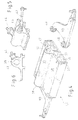
- FIG. 5 shows how a recorded in the channel 41 steering linkage 42 is protected by a bellows 43 frontally led out of the channel 41. Furthermore, FIG. 5 shows a connection device 44 for receiving a steering shaft. In Figure 6 it is clearly shown that the attachment device 44 protrudes slightly angled from the elevation 39. The attachment device 44 is an opening of the survey 39 used to prevent rotation.
- Figure 4 shows that in each case in the two outer chambers 36, a transverse link 46 is receivable.
- each holes 47 are introduced in the wide side wall 38, are guided by the appropriate fastening means which connect the wishbone 46 with the aluminum profile 2
- the fasteners can cohesively or by means of Screw connections to be connected to the subframe 1.
- the wishbone 46 is already mounted, while the wishbone 46 is shown on the opposite side shortly before mounting. It can be seen here that disc-shaped rubber bearings 48 are arranged on the control arm 46 for vibration isolation.
- the subframe 1 when the subframe 1 is cut off from a continuously extruded base member by means of suitable cutting devices.
- the subframe 1 may according to the invention also consist of extruded individual parts which are connected to each other, wherein preferably a cohesive connection z. B. is conceivable by welding. But other types of connections are possible.
- the invention is not limited to the embodiments described but also includes all equivalent means or combinations.
- the spatial-geometric configuration of the subframe 1 may be different according to the particular application.
- Suspension components may for example be wishbones and / or steering sticks and / or the like.
Description
Die Erfindung betrifft ein Kraftfahrzeug mit einem Hilfsrahmen zur Aufnahme von Aufhängungsbauteilen, um die Aufhängungsbauteile mit einem Fahrzeugaufbau zu verbinden, wobei der Hilfsrahmen als stranggepreßtes Aluminiumprofil ausgebildet ist, der in einer horizontalen Richtung stranggepreßt ist.The invention relates to a motor vehicle with a subframe for receiving suspension components to connect the suspension components to a vehicle body, wherein the subframe is formed as an extruded aluminum profile which is extruded in a horizontal direction.
Derartige Hilfsrahmen sind bekannt. Diese werden in Personenwagen zur Verbindung von Aufhängungsbauteilen mit dem Fahrzeugaufbau eingesetzt. Um sicherzustellen, daß der Personenwagen z. B. bei extremen Fahrmanövern eine gute dynamische Leistungsfähigkeit aufweist, muß der Hilfsrahmen eine ausreichende Steifigkeit und Festigkeit aufweisen. Üblicherweise werden die bekannten Hilfsrahmen aus Stahl, z. B. aus geformten Metallblechen, Rohren oder aus Gußstücken hergestellt. Der Hilfsrahmen kann mit oder ohne Gummilager mit dem Fahrzeugaufbau verbunden werden. Diese derart hergestellten Hilfsrahmen sind jedoch sehr schwer. Um das Gewicht zu reduzieren ist bekannt, daß die Aufhängungsbauteile aus Aluminium hergestellt werden. Dies können z. B. Querlenker, Lenkstöcke oder Dämpferstangen sein, die an dem Hilfsrahmen befestigt werden. Aluminium ist im Vergleich zu Stahl allerdings teuer. Derzeit betragen die Unterschiede von Aluminium zu Stahl ca. das Fünffache im Materialpreis bzw. ca. das Dreifache des Herstellungspreises des erfindungsgemäßen Hilfsrahmens gegenüber dem Stande der Technik.Such subframes are known. These are used in passenger cars for connecting suspension components to the vehicle body. To ensure that the car z. B. has a good dynamic performance in extreme maneuvers, the subframe must have sufficient rigidity and strength. Usually, the known subframe made of steel, z. B. made of molded metal sheets, pipes or castings. The subframe can be connected with or without a rubber mount to the vehicle body. However, these subframes made in this way are very heavy. To reduce the weight it is known that the suspension components are made of aluminum. This can z. B. wishbones, steering sticks or damper rods, which are attached to the subframe. Aluminum is expensive compared to steel. Currently, the differences from aluminum to steel are approximately five times the material price or approximately three times the production price of the subframe according to the invention over the prior art.
Nachteilig ist weiterhin, daß die im Vergleich zu Stahl geringe Dichte des Aluminiums in Bezug auf eine Werkzeugausgestaltung und einen höheren Verschleiß des Werkzeugs wegen der Adhäsion des Stahlwerkzeugs und des Aluminiumblechs und wegen der im Vergleich zu Stahl geringeren Umformbarkeit des Blechmaterials aus Aluminium beachtet werden muß.A further disadvantage is that in comparison to steel low density of aluminum in terms of a tool design and a higher wear of the tool due to the adhesion of the steel tool and the aluminum sheet and because of the lower compared to steel formability of the sheet material made of aluminum must be considered.
Die EP 1 270 374 A2, die dem Oberbegriff des Anspruch 1 zugrundeliegt, betrifft einen Querträger einer Kraftfahrzeugaufhängung mit einem zentralen Grundkörper und zwei separaten Seitenelementen. Der zentrale Grundkörper ist stranggepreßt.The EP 1 270 374 A2, which is based on the preamble of claim 1, relates to a cross member of a motor vehicle suspension with a central body and two separate side elements. The central body is extruded.
Auch die US 5,593,001 offenbart einen stranggepreßten Querträger.Also US 5,593,001 discloses an extruded cross member.
Ein Hilfsrahmen mit einem Leichtmetall-Gussgehäuse einer Zahnstangenlenkung und an diesem angeordneten konsolartigen seitlichen Befestigungsarmen mit Lagern zur lösbaren Anordnung an einem Fahrzeugaufbau und Halterungsarmen mit Lagern zur schwenkbaren Anlenkung von Radführungslenkern ist in der EP 0 779 204 A1 offenbart. Der Hilfsrahmen ist als Anordnungsmodul für Aggregate und/oder Aggregatteile und als Montagemodul mit definierten Anschlussstellen der Aggregate und/oder Aggregatteile ausgebildet.A subframe with a light metal cast housing of a rack and pinion steering and arranged thereon console-like lateral mounting arms with bearings for releasable arrangement on a vehicle body and support arms with bearings for the pivotable articulation of Radführungslenkern is disclosed in EP 0 779 204 A1. The subframe is designed as an assembly module for units and / or unit parts and as an assembly module with defined connection points of the units and / or unit parts.
Der Erfindung liegt die Aufgabe zugrunde, einen verbesserten Hilfsrahmen zur Verfügung zu stellen, der wesentlich leichter und dabei in der Herstellung preiswerter ist.The invention has for its object to provide an improved subframe available, which is much easier and cheaper to manufacture.
Erfindungsgemäß wird die Aufgabe dadurch gelöst, dass der Hilfsrahmen ein Lenkgehäuse aufweist, wobei der Hilfsrahmen einstückig mit dem Lenkgehäuse ausgebildet ist, und wobei das Aluminiumprofil als rechteckiger Hohlkörper mit Kammern ausgebildet ist, die stirnseitig geöffnet sind, und wobei das Aluminiumprofil an einer Breitseitenwandung eine geschlossene Erhebung mit einem im wesentlichen zylindrischen Kanal aufweist, die das Lenkgehäuse bilden.According to the invention the object is achieved in that the subframe has a steering housing, wherein the subframe is formed integrally with the steering housing, and wherein the aluminum profile is formed as a rectangular hollow body with chambers which are open at the front, and wherein the aluminum profile on a broad side wall a closed Has elevation with a substantially cylindrical channel, which form the steering housing.
Der Erfindung liegt die Erkenntnis zugrunde, daß sich Aluminium im Gegensatz zu Stahl durch Strangpressen relativ einfach und kostengünstig in beliebig komplizierte Profilformen bringen läßt. Strangpressen ist somit eine alternative Herstellungsvariante für Hilfsrahmen. Hierbei wird lediglich eine Vorrichtung benötigt um ein Basisteil durch Strangpressen herzustellen. Um leichte Hilfsrahmen zu erhalten, kann das Basisteil zweckmäßig mittels Schneidvorrichtungen in Hilfsrahmen mit den gewünschten Abmessungen geschnitten werden. Dies ist auch deshalb günstig, da hierdurch ein reproduzierbarer Herstellungsprozeß erreicht wird, der die Kosten erheblich reduziert. Vorteilhaft ist hierbei zudem, daß Aluminium im Vergleich zu Stahl wesentlich widerstandsfähiger gegen Korrosionseinflüsse ist.The invention is based on the finding that aluminum can be relatively easily and inexpensively bring in arbitrarily complicated profile shapes by extrusion in contrast to steel. Extrusion is thus an alternative production variant for subframe. Here, only one device is required to produce a base part by extrusion. In order to obtain lightweight subframes, the base part can be conveniently cut by means of cutting devices in subframe with the desired dimensions. This is also beneficial because it achieves a reproducible manufacturing process that significantly reduces costs. Another advantage here is that aluminum is much more resistant to corrosion than steel.
Günstig im Sinne der Erfindung ist, wenn das Lenkgehäuse einstückig mit dem Hilfsrahmen hergestellt wird. Hierdurch wird eine weitere, erhebliche Gewichts- und Kostenreduzierung erreicht.Favorable for the purposes of the invention is when the steering housing is made in one piece with the subframe. As a result, a further, significant weight and cost reduction is achieved.
Weitere vorteilhafte Ausgestaltungen sind in den Unteransprüchen und der folgenden Figurenbeschreibung beschrieben. Es zeigen die Figuren 4 bis 6 ein Ausführungsbeispiel der Erfindung, wobei die Figuren 1 bis 3 Ausführungsformen außerhalb des Umfangs von Anspruch 1 zeigen:
- Fig. 1
- ein stranggepreßtes Aluminiumprofil in einer perspektivischen Ansicht,
- Fig. 2
- eine zweite Ausführungsform eines Aluminiumprofils,
- Fig. 3
- eine dritte Ausführungsform eines Aluminiumprofils,
- Fig. 4
- ein stranggepreßtes Aluminiumprofil mit integriertem Lenkgehäuse,
- Fig. 5
- eine perspektivische Teilansicht aus
Figur 4 mit montierten Lenkgestänge, - Fig. 6
- eine Teil-Seitenansicht aus
Figur 4.
- Fig. 1
- an extruded aluminum profile in a perspective view,
- Fig. 2
- a second embodiment of an aluminum profile,
- Fig. 3
- a third embodiment of an aluminum profile,
- Fig. 4
- an extruded aluminum profile with integrated steering housing,
- Fig. 5
- 3 is a partial perspective view of Figure 4 with mounted steering linkage,
- Fig. 6
- a partial side view of Figure 4.
In den unterschiedlichen Figuren sind gleiche Teile mit denselben Bezugszeichen versehen, so daß sie in der Regel auch nur einmal beschrieben werden.In the different figures, the same parts are provided with the same reference numerals, so that they are usually described only once.
Figur 1 zeigt einen Hilfsrahmen 1, der als stranggepreßtes Aluminiumprofil 2 ausgebildet ist. Das Aluminiumprofil 2 ist vorzugsweise in einer vertikalen Richtung stranggepreßt. Die vertikale Richtung wird hierbei als von oben nach unten bzw. von unten nach oben definiert. Das Aluminiumprofil 2 ist im wesentlichen viereckig mit Querstreben 3 und senkrecht dazu angeordneten Längsstreben 4 ausgebildet. Die Längsstreben 4 und Querstreben 3 umfassen eine Öffnung 6 des Hilfsrahmens 1. Die Längsstreben 4 verbreitern sich jeweils von einer Querstrebe 3 zur dazu gegenüberliegenden Querstrebe 3. An seinen Ecken 7 ist das Aluminiumprofil 2 abgerundet, wobei innere Übergänge jeweils von den Querstreben 3 zu den Längstreben 4 innerhalb der Öffnung 6 verrundet sind. Außenseitig sind an den Ecken 7 Lagerohren 8 angeordnet. Die Lagerohren 8 weisen jeweils runde Durchgangslöcher 9 auf. In den Durchgangslöchern 9 können geeignete Befestigungsmittel aufgenommen werden, mit denen der Hilfsrahmen 1 mit dem Fahrzeugaufbau verbunden werden kann. Zur Schwingungsisolation können die Befestigungsmittel in Gummilagern oder dergleichen aufgenommen sein, die an die Durchgangslöcher 9 angepaßt sind. Hierbei können scheibenförmige Gummilager an den Rändern der Durchgangslöcher 9 anliegen, oder vorzugsweise Gummilager mit einer Durchgangsöffnung in die Durchgangslöcher 9 eingesteckt werden.Figure 1 shows an auxiliary frame 1, which is formed as an extruded aluminum profile 2. The aluminum profile 2 is preferably extruded in a vertical direction. The vertical direction is defined here from top to bottom or from bottom to top. The aluminum profile 2 is substantially square with transverse struts 3 and perpendicular thereto arranged
In den jeweiligen Querstreben 3 und Längsstreben 4 sind Ausnehmungen 11 eingebracht. Die Ausnehmungen 11 weisen verschiedene geometrische Ausgestaltungen auf, wobei die Ausnehmungen 11 in den Querstreben 3 vorzugsweise jeweils rechteckförmig ausgestaltet sind. Die jeweils diametral zu einer Mittelachse Y-Y gegenüberliegenden Ausnehmungen 11 in den Längsstreben 4 weisen ebenfalls jeweils eine gleichartige Ausgestaltung auf. Der in der Figur 1 dargestellte Hilfsrahmen 1 ist ein sogenannter Perimeterrahmen, der vorzugsweise bei größeren Personenwagen der Mittelklasse Verwendung finden kann.In the respective transverse struts 3 and
Figur 2 zeigt eine zweite Ausführungsform des Hilfsrahmens 1, der als stranggepreßtes Aluminiumprofil 2 ausgebildet ist, allerdings mit dem Unterschied, daß der Hilfsrahmen 1 in dem dargestellten Ausführungsbeispiel als Vollkörper 12 hergestellt ist. Der Vollkörper 12 weist an seinen Ecken 13 Lagerohren 14 mit im wesentlichen dreieckförmigen Durchgangslöchern 16 auf. Die Durchgangslöcher 16 können aber auch ähnlich wie zu Figur 1 beschrieben rund ausgestaltet sein. Eine Befestigung des Hilfsrahmens 1 und insbesondere die Maßnahmen zur Schwingungsisolierung sind ähnlich wie zu Figur 1 beschrieben. Des Weiteren weist der Vollkörper 12 bevorzugt systematisch eingebrachte, dreieckförmige Ausnehmungen 11 auf. Der in Figur 2 dargestellte Hilfsrahmen 1 kann vorzugsweise bei Kleinwagen eingesetzt werden.Figure 2 shows a second embodiment of the subframe 1, which is formed as an extruded aluminum profile 2, but with the difference that the subframe 1 is made in the illustrated embodiment as a
Sowohl die Ausnehmungen 11 als auch die Durchgangslöcher 9 und 16 werden jeweils bei der Herstellung des Hilfsrahmens 1 während des Strangpressens eingebracht, damit der Hilfsrahmen 1 zusätzlich zu dem Gewichtsverlust, der durch die erfindungsgemäße Ausgestaltung mittels des stranggepreßten Aluminiumprofils 2 erreichbar ist in seinem Gewicht reduziert wird. Hierbei sollten die jeweiligen Ausnehmungen 11 und Durchgangslöcher 9 und 16 aber derart ausgestaltet sein, daß die Festigkeitseigenschaften des Aluminiumprofils 2 nicht reduziert werden. Die Ausnehmungen 11 und Durchgangslöcher 9 und 16 können selbstverständlich auch nach dem Strangpressen in den Hilfsrahmen 1 eingearbeitet werden.Both the
Figur 3 zeigt eine dritte Ausführungsform eines Hilfsrahmens 1, der als stranggepreßtes Aluminiumprofil 2 ausgebildet ist. Das Aluminiumprofil 2 ist allerdings in einer horizontalen Richtung stranggepreßt. Die horizontale Richtung wird hierbei als Richtung von rechts nach links, von links nach rechts oder von vorne nach hinten oder von hinten nach vorne definiert. Das Aluminiumprofil 2 ist als rechteckige Platte 17 mit Breitseiten 18 und dazu senkrechten Längsseiten 19 ausgebildet. In dem Aluminiumprofil 2 sind Kammern 21 eingebracht. Die Kammern 21 erstrecken sich parallel zu den Breitseiten 18 und jeweils parallel zueinander durchgehend von einer längsseitigen Stirnseite 22 zu einer dazu gegenüberliegenden längsseitigen Stirnseite. Seitlich sind benachbarte Kammern 21 mittels durchgehender Stege 23 getrennt. An den Breitseiten 18 weist das Aluminiumprofil 2 jeweils parallel zu den Kammern 21 verlaufende Aufnahmevorrichtungen 24 auf. Die Aufnahmevorrichtungen 24 sind jeweils an den Breitseiten 18 geöffnet, so daß die Aufnahmevorrichtung 24 Ober- und Unterseitige Flansche 26 aufweist. In den Ober- und Unterseitigen Flanschen 26 sind jeweils zueinander kongruente Bohrungen 27 eingebracht. Vorzugsweise kann von der Aufnahmevorrichtung 24 ein Querlenker aufgenommen werden, der mittels geeigneter Befestigungsvorrichtungen, die durch die Bohrungen 27 geführt werden befestigt wird. Zur Schwingungsisolierung kann der Querlenker scheibenförmige Gummilager aufweisen, die jeweils an einer zum Querlenker weisenden Seite des jeweiligen Flansches 26 und an dem Querlenker anliegen.Figure 3 shows a third embodiment of a subframe 1, which is formed as an extruded aluminum profile 2. However, the aluminum profile 2 is extruded in a horizontal direction. The horizontal direction is here as the direction from right to left, from left to right or from the front defined backwards or from back to front. The aluminum profile 2 is formed as a
Weiter weist der Hilfsrahmen 1 an einer Oberfläche Befestigungsmittel 28 zur Befestigung des Hilfsrahmens 1 mit dem Fahrzeugaufbau auf. Die Befestigungsmittel 28 sind mit einem Befestigungsende 29 in Bohrungen 31 eingesetzt und mittels stoffschlüssiger Verbindung, z. B. Schweißen mit dem Hilfsrahmen 1 verbunden. Die Befestigungsmittel 28 stehen von dem Hilfsrahmen 1 ab und verlaufen in dem dargestellten Ausführungsbeispiel von dem Befestigungsende 29 leicht gebogen in Richtung zur Breitseite 18. An ihren freien Enden 32 weisen die Befestigungsmittel 28 einen hammerkopfförmigen Fortsatz 33 auf. Die Befestigungsmittel 28 können aus Vollmaterial oder vorzugsweise aus Hohlkörpern wie z. B. Rohren bestehen. Der hammerkopfförmige Fortsatz 33 ist als Hohlkörper zur Aufnahme von Bolzen geeignet, mit denen eine Verbindung zum Fahrzeugaufbau herstellbar ist. Zur Schwingungsisolierung kann der hammerkopfförmige Fortsatz 33 Gummilager aufweisen, in denen die Bolzen gelagert sind. Selbstverständlich können die Befestigungsmittel 28 auch andere Ausgestaltungen als die in Figur 3 dargestellte, beispielhafte Ausführungsform aufweisen.Next, the subframe 1 on a surface fastening means 28 for attachment of the subframe 1 with the vehicle body. The fastening means 28 are inserted with a mounting
Zur weiteren Gewichtsreduzierung kann der Hilfsrahmen 1 z. B. fräsend bearbeitet werden, um Material zu entfernen. Beispielhafte Ausnehmungsbereiche sind in Figur 3 leicht schraffiert mit einer kurzgestrichelten Begrenzungslinie 34 dargestellt, wobei der Hilfsrahmen 1 z. B. knochenförmig ausgestaltet werden könnte.To further reduce weight of the subframe 1 z. B. machined to remove material. Exemplary recess areas are shown in FIG. 3 in a slightly hatched manner with a short-dashed
Die in den Figuren 1 bis 3 beschriebenen Hilfsrahmen 1 sind jeweils als stranggepreßtes Aluminiumprofil 2 von einem Basisteil, das kontinuierlich stranggepreßt ist mittels geeigneter Schneidvorrichtung auf die erforderlichen Abmessungen abgeschnitten. Das Aluminiumstrangpreßprofil 2 kann aber auch aus stranggepreßten Einzelteilen zusammengesetzt werden, wobei vorzugsweise eine stoffschlüssige Verbindung, wie z. B. mittels Schweißen angewendet wird.The subframe 1 described in FIGS. 1 to 3 are in each case cut as an extruded aluminum profile 2 from a base part which is continuously extruded by means of a suitable cutting device to the required dimensions. However, the extruded aluminum 2 may also be composed of extruded individual parts, wherein preferably a cohesive connection, such. B. is applied by welding.
Figur 4 zeigt einen Hilfsrahmen 1, der ein Lenkgehäuse 35 aufweist, wobei der Hilfsrahmen 1 einstückig mit dem Lenkgehäuse 35 ausgebildet ist. Der Hilfsrahmen 1 mit dem Lenkgehäuse 35 ist als stranggepreßtes Aluminiumprofil 2 ausgebildet. Der Hilfsrahmen 1 ist vorzugsweise quer zu einer Fahrzeuglängsachse, und somit in einer horizontalen Richtung von rechts nach links oder von links nach rechts stranggepreßt.FIG. 4 shows an auxiliary frame 1, which has a steering
Das Aluminiumprofil 2 ist als rechteckiger Hohlkörper mit vorzugsweise vier Kammern 36 ausgebildet. Selbstverständlich können auch mehr oder weniger Kammern 36 vorgesehen sein. Die Kammern 36 sind stirnseitig geöffnet, wobei jeweils benachbarte Kammern 36 mittels eines Steges 37 getrennt sind. Die beiden äußeren Kammern 36 sind ebenfalls mittels eines Steges 37 geschlossen. An einer Breitseitenwandung 38 weist das Aluminiumprofil 2 eine geschlossene Erhebung 39 mit einem im wesentlichen zylindrischen Kanal 41 auf. Die Erhebung 39 und der Kanal 41 bilden zusammen das Lenkgehäuse 34 aus. Die Erhebung 39 mit dem Kanal 41 sind im dargestellten Ausführungsbeispiel exzentrisch zu einer Mittelachse Y-Y angeordnet.The aluminum profile 2 is formed as a rectangular hollow body with preferably four
Eine Vergrößerung in Figur 5 zeigt, wie ein in dem Kanal 41 aufgenommenes Lenkgestänge 42 von einem Faltenbalg 43 geschützt stirnseitig aus dem Kanal 41 herausgeführt ist. Weiter ist in Figur 5 eine Anbindungsvorrichtung 44 zur Aufnahme einer Lenkwelle dargestellt. In Figur 6 ist deutlich gezeigt, daß die Anbindungsvorrichtung 44 etwas winklig von der Erhebung 39 absteht. Die Anbindungsvorrichtung 44 ist eine Öffnung der Erhebung 39 drehsicher eingesetzt.An enlargement in Figure 5 shows how a recorded in the
Weiterhin zeigt Figur 4, daß jeweils in den beiden äußeren Kammern 36 ein Querlenker 46 aufnehmbar ist. Zur Befestigung des Querlenkers 46 sind in der Breitseitenwandung 38 jeweils Bohrungen 47 eingebracht, durch die geeignete Befestigungsmittel geführt werden, die den Querlenker 46 mit dem Aluminiumprofil 2 verbinden Die Befestigungsmittel können stoffschlüssig oder mittels Schraubverbindungen mit dem Hilfsrahmen 1 verbunden sein. Auf einer Seite der Figur 4 ist der Querlenker 46 bereits montiert, während der Querlenker 46 auf der dazu gegenüberliegenden Seite kurz vor der Montage dargestellt ist. Erkennbar ist hier, daß zur Schwingungsisolierung scheibenförmige Gummilager 48 an dem Querlenker 46 angeordnet sind.Furthermore, Figure 4 shows that in each case in the two
Selbstverständlich ist es im Sinne der Erfindung günstig, wenn der Hilfsrahmen 1 aus einem kontinuierlich stranggepreßten Basisteil mittels geeigneter Schneidvorrichtungen abgeschnitten wird. Der Hilfsrahmen 1 kann aber erfindungsgemäß auch aus stranggepreßten Einzelteilen bestehen, die miteinander verbunden werden, wobei vorzugsweise eine stoffschlüssige Verbindung z. B. mittels Schweißen denkbar ist. Aber auch andere Verbindungsarten sind möglich.Of course, it is favorable in the context of the invention, when the subframe 1 is cut off from a continuously extruded base member by means of suitable cutting devices. The subframe 1 may according to the invention also consist of extruded individual parts which are connected to each other, wherein preferably a cohesive connection z. B. is conceivable by welding. But other types of connections are possible.
Die Erfindung ist nicht auf die beschriebenen Ausführungsformen beschränkt, sondern umfaßt auch alle gleichwirkenden Mittel oder Kombinationen. Insbesondere die räumlich-geometrische Ausgestaltung des Hilfsrahmens 1 kann entsprechend dem jeweiligen Verwendungszweck eine andere sein. Aufhängungsbauteile können zum Beispiel Querlenker und/oder Lenkstöcke und/oder dergleichen sein.The invention is not limited to the embodiments described but also includes all equivalent means or combinations. In particular, the spatial-geometric configuration of the subframe 1 may be different according to the particular application. Suspension components may for example be wishbones and / or steering sticks and / or the like.
Claims (4)
- Subframe (1), preferably for motor vehicles, for holding suspended components, in order to connect them to a vehicle body, the subframe (1) being embodied as an extruded aluminium section (2) which is extruded in a horizontal direction,
characterized in that
the subframe (1) has a steering gear housing (35), the subframe (1) being embodied in one piece with the steering gear housing (35), and the aluminium section (2) being embodied as a rectangular hollow body having chambers (36) which are open at the ends, and the aluminium section (2) having, on one lateral side wall (38), a closed elevation (39) with an essentially cylindrical duct (41), the elevation forming the steering gear housing (34). - Subframe (1) according to Claim 1,
characterized in that
a transverse link (46) can be held by each of the two outer chambers (36). - Subframe (1) according to Claim 1 or 2,
characterized in that
the subframe (1) is cut off from a continuously extruded base part by means of suitable cutting devices. - Subframe (1) according to one of the preceding claims,
characterized in that
the subframe (1) is composed of extruded individual parts, which are connected to one another.
Priority Applications (2)
| Application Number | Priority Date | Filing Date | Title |
|---|---|---|---|
| DE50303842T DE50303842D1 (en) | 2003-08-08 | 2003-08-08 | Subframe for vehicles |
| EP20030102483 EP1504983B1 (en) | 2003-08-08 | 2003-08-08 | Vehicle subframe |
Applications Claiming Priority (1)
| Application Number | Priority Date | Filing Date | Title |
|---|---|---|---|
| EP20030102483 EP1504983B1 (en) | 2003-08-08 | 2003-08-08 | Vehicle subframe |
Publications (2)
| Publication Number | Publication Date |
|---|---|
| EP1504983A1 EP1504983A1 (en) | 2005-02-09 |
| EP1504983B1 true EP1504983B1 (en) | 2006-06-14 |
Family
ID=33547784
Family Applications (1)
| Application Number | Title | Priority Date | Filing Date |
|---|---|---|---|
| EP20030102483 Expired - Fee Related EP1504983B1 (en) | 2003-08-08 | 2003-08-08 | Vehicle subframe |
Country Status (2)
| Country | Link |
|---|---|
| EP (1) | EP1504983B1 (en) |
| DE (1) | DE50303842D1 (en) |
Cited By (7)
| Publication number | Priority date | Publication date | Assignee | Title |
|---|---|---|---|---|
| DE102011004715A1 (en) | 2011-02-25 | 2012-08-30 | Ford Global Technologies, Llc | Integrated auxiliary frame e.g. extruded aluminum profile, for motor car, has bearing resiliently mounted in axial direction of axially movable rack gear, and drive pinion rotatably mounted and engaged with tooth of rack gear |
| US8403347B2 (en) | 2005-09-13 | 2013-03-26 | Ksm Castings Group Gmbh | Front-axle bracket, in particular for motor vehicles |
| DE202014105548U1 (en) | 2014-10-09 | 2015-01-09 | Ford Global Technologies, Llc | Handlebar for connecting a vehicle wheel to a vehicle and vehicle suspension |
| DE102014220443A1 (en) | 2014-10-09 | 2016-04-14 | Ford Global Technologies, Llc | Handlebar for connecting a vehicle wheel to a vehicle and vehicle suspension |
| DE102014220444A1 (en) | 2014-10-09 | 2016-04-14 | Ford Global Technologies, Llc | Handlebar for connecting a vehicle wheel to a vehicle and vehicle suspension |
| DE102020207517A1 (en) | 2020-06-17 | 2021-12-23 | Volkswagen Aktiengesellschaft | Arrangement of a steering gear and a subframe for a motor vehicle |
| US20220363317A1 (en) * | 2021-05-11 | 2022-11-17 | Ford Global Technologies, Llc | Vibration dampening vehicle subframe |
Families Citing this family (12)
| Publication number | Priority date | Publication date | Assignee | Title |
|---|---|---|---|---|
| WO2009059591A2 (en) | 2007-11-08 | 2009-05-14 | Ksm Castings Gmbh | Front axle carrier for motor vehicles |
| DE102009043474A1 (en) * | 2008-10-30 | 2010-05-12 | Ksm Castings Gmbh | Front axle for a motor vehicle and method for its production |
| DE112010002862A5 (en) | 2009-07-06 | 2012-11-29 | Ksm Castings Gmbh | Axle carrier, in particular front axle carrier for motor vehicles |
| DE102011115387A1 (en) | 2010-11-02 | 2012-05-03 | Ksm Castings Gmbh | Axle carrier, in particular front axle carrier for motor vehicles |
| FR2986489B1 (en) * | 2012-02-08 | 2014-03-14 | Peugeot Citroen Automobiles Sa | MONOBLOC EXTRUDE ENGINE CRADLE |
| EP2653369B1 (en) * | 2012-04-20 | 2018-06-06 | Festo AG & Co. KG | Lightweight construction structure |
| FR2993849B1 (en) * | 2012-07-26 | 2015-11-06 | Peugeot Citroen Automobiles Sa | DIRECTIONAL TRAIN FOR VEHICLE AND VEHICLE COMPRISING SUCH A DIRECTIONAL TRAIN |
| FR3006278B1 (en) * | 2013-05-31 | 2016-12-02 | Peugeot Citroen Automobiles Sa | CRADLE FOR A MOTOR VEHICLE ROLLER |
| DE102013220319A1 (en) * | 2013-10-09 | 2015-04-09 | Zf Friedrichshafen Ag | Subframe with axle beam and strut tower |
| US9394002B2 (en) * | 2014-03-20 | 2016-07-19 | Ford Global Technologies, Llc | Extruded metal sub-frame for a vehicle |
| DE102014111395B4 (en) | 2014-08-11 | 2020-06-10 | Knorr-Bremse Systeme für Nutzfahrzeuge GmbH | Assembly for a motor vehicle, comprising a subframe and a steering gear |
| CN107856742A (en) * | 2017-11-03 | 2018-03-30 | 宁波拓普汽车电子有限公司 | A kind of universal aluminium subframe for being applied to fuel vehicle and EV electric cars |
Family Cites Families (3)
| Publication number | Priority date | Publication date | Assignee | Title |
|---|---|---|---|---|
| JP2553451B2 (en) * | 1993-06-11 | 1996-11-13 | 山川工業株式会社 | Mounting support member and manufacturing method thereof |
| EP0779204B1 (en) * | 1995-12-11 | 1999-11-03 | Volkswagen Aktiengesellschaft | Subframe comprising the cast light-alloy housing of a rack-and-pinion steering |
| ITTO20010627A1 (en) * | 2001-06-29 | 2002-12-29 | Sistemi Sospensioni Spa | CROSSING FOR A MOTOR VEHICLE SUSPENSION. |
-
2003
- 2003-08-08 DE DE50303842T patent/DE50303842D1/en not_active Expired - Lifetime
- 2003-08-08 EP EP20030102483 patent/EP1504983B1/en not_active Expired - Fee Related
Cited By (10)
| Publication number | Priority date | Publication date | Assignee | Title |
|---|---|---|---|---|
| US8403347B2 (en) | 2005-09-13 | 2013-03-26 | Ksm Castings Group Gmbh | Front-axle bracket, in particular for motor vehicles |
| US9016704B2 (en) | 2005-09-13 | 2015-04-28 | Ksm Castings Group Gmbh | Front-axle bracket, in particular for motor vehicles |
| DE102011004715A1 (en) | 2011-02-25 | 2012-08-30 | Ford Global Technologies, Llc | Integrated auxiliary frame e.g. extruded aluminum profile, for motor car, has bearing resiliently mounted in axial direction of axially movable rack gear, and drive pinion rotatably mounted and engaged with tooth of rack gear |
| DE202014105548U1 (en) | 2014-10-09 | 2015-01-09 | Ford Global Technologies, Llc | Handlebar for connecting a vehicle wheel to a vehicle and vehicle suspension |
| DE102014220443A1 (en) | 2014-10-09 | 2016-04-14 | Ford Global Technologies, Llc | Handlebar for connecting a vehicle wheel to a vehicle and vehicle suspension |
| DE102014220444A1 (en) | 2014-10-09 | 2016-04-14 | Ford Global Technologies, Llc | Handlebar for connecting a vehicle wheel to a vehicle and vehicle suspension |
| DE102014220443B4 (en) | 2014-10-09 | 2021-12-23 | Ford Global Technologies, Llc | Handlebars for connecting a vehicle wheel to a vehicle and vehicle wheel suspension |
| DE102020207517A1 (en) | 2020-06-17 | 2021-12-23 | Volkswagen Aktiengesellschaft | Arrangement of a steering gear and a subframe for a motor vehicle |
| US20220363317A1 (en) * | 2021-05-11 | 2022-11-17 | Ford Global Technologies, Llc | Vibration dampening vehicle subframe |
| US11884327B2 (en) * | 2021-05-11 | 2024-01-30 | Ford Global Technologies, Llc | Vibration dampening vehicle subframe |
Also Published As
| Publication number | Publication date |
|---|---|
| EP1504983A1 (en) | 2005-02-09 |
| DE50303842D1 (en) | 2006-07-27 |
Similar Documents
| Publication | Publication Date | Title |
|---|---|---|
| EP1504983B1 (en) | Vehicle subframe | |
| EP2222534B1 (en) | Front axle carrier for motor vehicles | |
| DE19710849B4 (en) | Air spring for air suspension axles | |
| DE102006055730A1 (en) | MacPherson strut | |
| DE102006013550A1 (en) | Subframe for motor vehicles, vehicle body with a mounted subframe, adapter part for a subframe and methods for mounting a drive unit on such a subframe | |
| DE3718841C2 (en) | ||
| DE202008017275U1 (en) | Front axle, especially for motor vehicles | |
| EP2663463B1 (en) | Support of an axle transmission in the rear region of a passenger vehicle | |
| DE102009012350A1 (en) | Chassis for tractor, has middle assembly formed as hollow section, and front and rear assemblies with longitudinal beams formed from closed profile parts, where front or rear assembly is detachably attached to middle assembly | |
| DE102006013547A1 (en) | Sub-frame for motor vehicle, especially for front axle, has adapter part for providing replacement bearing point offset in longitudinal direction relative to sub-frame side bearing point, especially for increasing bearing distance | |
| DE10028278B4 (en) | portal axis | |
| DE102013011546A1 (en) | Subframe for a motor vehicle | |
| DE102006041099B4 (en) | Frame element for a motor vehicle and its mounting arrangement on a motor vehicle body | |
| EP1321692B1 (en) | Engine mount | |
| DE102009043913A1 (en) | Vehicle body with modular rear axle construction | |
| DE102016009395A1 (en) | Storage arrangement of an electric drive train to a motor vehicle shell | |
| EP1533151B1 (en) | Motor vehicle independent wheel suspension | |
| EP3696054A1 (en) | Modular vehicle chassis with rear frame overhang | |
| DE10257259B4 (en) | Front frame for a motor vehicle and aluminum body produced therewith | |
| DE102016006848A1 (en) | Achsträger for a multi-track motor vehicle | |
| DE102006014982A1 (en) | Transducer element for supporting an impact absorber | |
| EP2683842A2 (en) | Chassis part, in particular junction element or sub-frame | |
| DE102004055197A1 (en) | Tunnel bridge for a motor vehicle | |
| EP1619055B1 (en) | Single-shell front lateral arm | |
| DE10016883A1 (en) | Motor vehicle has connecting points on separate front structure and on body to enable front structure to be mounted on body by joining it to body in vertical direction |
Legal Events
| Date | Code | Title | Description |
|---|---|---|---|
| PUAI | Public reference made under article 153(3) epc to a published international application that has entered the european phase |
Free format text: ORIGINAL CODE: 0009012 |
|
| AK | Designated contracting states |
Kind code of ref document: A1 Designated state(s): AT BE BG CH CY CZ DE DK EE ES FI FR GB GR HU IE IT LI LU MC NL PT RO SE SI SK TR |
|
| AX | Request for extension of the european patent |
Extension state: AL LT LV MK |
|
| 17P | Request for examination filed |
Effective date: 20050809 |
|
| AKX | Designation fees paid |
Designated state(s): DE FR GB |
|
| GRAP | Despatch of communication of intention to grant a patent |
Free format text: ORIGINAL CODE: EPIDOSNIGR1 |
|
| GRAS | Grant fee paid |
Free format text: ORIGINAL CODE: EPIDOSNIGR3 |
|
| GRAA | (expected) grant |
Free format text: ORIGINAL CODE: 0009210 |
|
| AK | Designated contracting states |
Kind code of ref document: B1 Designated state(s): DE FR GB |
|
| REG | Reference to a national code |
Ref country code: GB Ref legal event code: FG4D Free format text: NOT ENGLISH |
|
| REF | Corresponds to: |
Ref document number: 50303842 Country of ref document: DE Date of ref document: 20060727 Kind code of ref document: P |
|
| GBT | Gb: translation of ep patent filed (gb section 77(6)(a)/1977) |
Effective date: 20060923 |
|
| ET | Fr: translation filed | ||
| PLBE | No opposition filed within time limit |
Free format text: ORIGINAL CODE: 0009261 |
|
| STAA | Information on the status of an ep patent application or granted ep patent |
Free format text: STATUS: NO OPPOSITION FILED WITHIN TIME LIMIT |
|
| 26N | No opposition filed |
Effective date: 20070315 |
|
| PGFP | Annual fee paid to national office [announced via postgrant information from national office to epo] |
Ref country code: FR Payment date: 20090806 Year of fee payment: 7 |
|
| PGFP | Annual fee paid to national office [announced via postgrant information from national office to epo] |
Ref country code: DE Payment date: 20090831 Year of fee payment: 7 Ref country code: GB Payment date: 20090708 Year of fee payment: 7 |
|
| GBPC | Gb: european patent ceased through non-payment of renewal fee |
Effective date: 20100808 |
|
| REG | Reference to a national code |
Ref country code: FR Ref legal event code: ST Effective date: 20110502 |
|
| REG | Reference to a national code |
Ref country code: DE Ref legal event code: R119 Ref document number: 50303842 Country of ref document: DE Effective date: 20110301 |
|
| PG25 | Lapsed in a contracting state [announced via postgrant information from national office to epo] |
Ref country code: FR Free format text: LAPSE BECAUSE OF NON-PAYMENT OF DUE FEES Effective date: 20100831 Ref country code: DE Free format text: LAPSE BECAUSE OF NON-PAYMENT OF DUE FEES Effective date: 20110301 |
|
| PG25 | Lapsed in a contracting state [announced via postgrant information from national office to epo] |
Ref country code: GB Free format text: LAPSE BECAUSE OF NON-PAYMENT OF DUE FEES Effective date: 20100808 |