EP1503707B1 - Ambulating knee joint - Google Patents
Ambulating knee joint Download PDFInfo
- Publication number
- EP1503707B1 EP1503707B1 EP03724237A EP03724237A EP1503707B1 EP 1503707 B1 EP1503707 B1 EP 1503707B1 EP 03724237 A EP03724237 A EP 03724237A EP 03724237 A EP03724237 A EP 03724237A EP 1503707 B1 EP1503707 B1 EP 1503707B1
- Authority
- EP
- European Patent Office
- Prior art keywords
- hinge assembly
- disk
- spring
- teeth
- angular displacement
- Prior art date
- Legal status (The legal status is an assumption and is not a legal conclusion. Google has not performed a legal analysis and makes no representation as to the accuracy of the status listed.)
- Expired - Lifetime
Links
- 210000000629 knee joint Anatomy 0.000 title description 4
- 230000033001 locomotion Effects 0.000 claims abstract description 84
- 230000007246 mechanism Effects 0.000 claims abstract description 26
- 230000006835 compression Effects 0.000 claims abstract description 23
- 238000007906 compression Methods 0.000 claims abstract description 23
- 230000006837 decompression Effects 0.000 claims abstract description 12
- JOYRKODLDBILNP-UHFFFAOYSA-N Ethyl urethane Chemical compound CCOC(N)=O JOYRKODLDBILNP-UHFFFAOYSA-N 0.000 claims abstract description 7
- 238000006073 displacement reaction Methods 0.000 claims description 33
- 230000004044 response Effects 0.000 claims description 12
- 230000009471 action Effects 0.000 claims description 4
- 210000003205 muscle Anatomy 0.000 abstract description 15
- 230000003278 mimic effect Effects 0.000 abstract description 5
- 230000000295 complement effect Effects 0.000 abstract description 3
- 210000003127 knee Anatomy 0.000 description 54
- 230000005021 gait Effects 0.000 description 19
- 230000035939 shock Effects 0.000 description 19
- 238000010521 absorption reaction Methods 0.000 description 18
- 239000000463 material Substances 0.000 description 10
- 210000002414 leg Anatomy 0.000 description 8
- 230000000712 assembly Effects 0.000 description 7
- 238000000429 assembly Methods 0.000 description 7
- 208000006011 Stroke Diseases 0.000 description 5
- 210000003414 extremity Anatomy 0.000 description 5
- 210000002683 foot Anatomy 0.000 description 5
- 239000011230 binding agent Substances 0.000 description 4
- 238000006243 chemical reaction Methods 0.000 description 4
- 210000000078 claw Anatomy 0.000 description 4
- 230000000452 restraining effect Effects 0.000 description 3
- 230000000630 rising effect Effects 0.000 description 3
- 230000001953 sensory effect Effects 0.000 description 3
- 210000001519 tissue Anatomy 0.000 description 3
- 210000004556 brain Anatomy 0.000 description 2
- 230000008859 change Effects 0.000 description 2
- 239000002131 composite material Substances 0.000 description 2
- 230000000991 decompressive effect Effects 0.000 description 2
- 230000007423 decrease Effects 0.000 description 2
- 239000013536 elastomeric material Substances 0.000 description 2
- 210000003811 finger Anatomy 0.000 description 2
- 210000004744 fore-foot Anatomy 0.000 description 2
- 230000006870 function Effects 0.000 description 2
- 210000000452 mid-foot Anatomy 0.000 description 2
- 230000004048 modification Effects 0.000 description 2
- 238000012986 modification Methods 0.000 description 2
- 230000004220 muscle function Effects 0.000 description 2
- 230000036316 preload Effects 0.000 description 2
- 230000000717 retained effect Effects 0.000 description 2
- 210000003371 toe Anatomy 0.000 description 2
- 230000007704 transition Effects 0.000 description 2
- 208000005137 Joint instability Diseases 0.000 description 1
- 206010023230 Joint stiffness Diseases 0.000 description 1
- 208000010428 Muscle Weakness Diseases 0.000 description 1
- 206010062575 Muscle contracture Diseases 0.000 description 1
- 206010028372 Muscular weakness Diseases 0.000 description 1
- 206010052904 Musculoskeletal stiffness Diseases 0.000 description 1
- 239000004677 Nylon Substances 0.000 description 1
- 206010033799 Paralysis Diseases 0.000 description 1
- 230000006978 adaptation Effects 0.000 description 1
- 229910052782 aluminium Inorganic materials 0.000 description 1
- XAGFODPZIPBFFR-UHFFFAOYSA-N aluminium Chemical compound [Al] XAGFODPZIPBFFR-UHFFFAOYSA-N 0.000 description 1
- 210000003423 ankle Anatomy 0.000 description 1
- 230000001447 compensatory effect Effects 0.000 description 1
- 238000010276 construction Methods 0.000 description 1
- 208000006111 contracture Diseases 0.000 description 1
- 230000001054 cortical effect Effects 0.000 description 1
- 230000000694 effects Effects 0.000 description 1
- 230000002349 favourable effect Effects 0.000 description 1
- 230000025561 forward locomotion Effects 0.000 description 1
- 230000001771 impaired effect Effects 0.000 description 1
- 230000008407 joint function Effects 0.000 description 1
- 239000010985 leather Substances 0.000 description 1
- 210000004932 little finger Anatomy 0.000 description 1
- 229910052751 metal Inorganic materials 0.000 description 1
- 239000002184 metal Substances 0.000 description 1
- 239000000203 mixture Substances 0.000 description 1
- 230000037230 mobility Effects 0.000 description 1
- 239000002991 molded plastic Substances 0.000 description 1
- 230000013663 muscle adaptation Effects 0.000 description 1
- 230000000926 neurological effect Effects 0.000 description 1
- 229920001778 nylon Polymers 0.000 description 1
- 230000000399 orthopedic effect Effects 0.000 description 1
- 230000036961 partial effect Effects 0.000 description 1
- 230000007170 pathology Effects 0.000 description 1
- 229920001296 polysiloxane Polymers 0.000 description 1
- 238000002360 preparation method Methods 0.000 description 1
- 230000002265 prevention Effects 0.000 description 1
- 230000002035 prolonged effect Effects 0.000 description 1
- 230000009467 reduction Effects 0.000 description 1
- 230000002829 reductive effect Effects 0.000 description 1
- 230000000284 resting effect Effects 0.000 description 1
- 230000035807 sensation Effects 0.000 description 1
- 229910052710 silicon Inorganic materials 0.000 description 1
- 239000010703 silicon Substances 0.000 description 1
- 230000000087 stabilizing effect Effects 0.000 description 1
- 229910001220 stainless steel Inorganic materials 0.000 description 1
- 239000010935 stainless steel Substances 0.000 description 1
- 238000005728 strengthening Methods 0.000 description 1
- 230000001225 therapeutic effect Effects 0.000 description 1
- 230000000007 visual effect Effects 0.000 description 1
Images


Classifications
-
- A—HUMAN NECESSITIES
- A61—MEDICAL OR VETERINARY SCIENCE; HYGIENE
- A61F—FILTERS IMPLANTABLE INTO BLOOD VESSELS; PROSTHESES; DEVICES PROVIDING PATENCY TO, OR PREVENTING COLLAPSING OF, TUBULAR STRUCTURES OF THE BODY, e.g. STENTS; ORTHOPAEDIC, NURSING OR CONTRACEPTIVE DEVICES; FOMENTATION; TREATMENT OR PROTECTION OF EYES OR EARS; BANDAGES, DRESSINGS OR ABSORBENT PADS; FIRST-AID KITS
- A61F5/00—Orthopaedic methods or devices for non-surgical treatment of bones or joints; Nursing devices; Anti-rape devices
- A61F5/01—Orthopaedic devices, e.g. splints, casts or braces
- A61F5/0102—Orthopaedic devices, e.g. splints, casts or braces specially adapted for correcting deformities of the limbs or for supporting them; Ortheses, e.g. with articulations
- A61F5/0123—Orthopaedic devices, e.g. splints, casts or braces specially adapted for correcting deformities of the limbs or for supporting them; Ortheses, e.g. with articulations for the knees
- A61F5/0125—Orthopaedic devices, e.g. splints, casts or braces specially adapted for correcting deformities of the limbs or for supporting them; Ortheses, e.g. with articulations for the knees the device articulating around a single pivot-point
-
- A—HUMAN NECESSITIES
- A61—MEDICAL OR VETERINARY SCIENCE; HYGIENE
- A61F—FILTERS IMPLANTABLE INTO BLOOD VESSELS; PROSTHESES; DEVICES PROVIDING PATENCY TO, OR PREVENTING COLLAPSING OF, TUBULAR STRUCTURES OF THE BODY, e.g. STENTS; ORTHOPAEDIC, NURSING OR CONTRACEPTIVE DEVICES; FOMENTATION; TREATMENT OR PROTECTION OF EYES OR EARS; BANDAGES, DRESSINGS OR ABSORBENT PADS; FIRST-AID KITS
- A61F5/00—Orthopaedic methods or devices for non-surgical treatment of bones or joints; Nursing devices; Anti-rape devices
- A61F5/01—Orthopaedic devices, e.g. splints, casts or braces
- A61F5/0102—Orthopaedic devices, e.g. splints, casts or braces specially adapted for correcting deformities of the limbs or for supporting them; Ortheses, e.g. with articulations
- A61F2005/0132—Additional features of the articulation
- A61F2005/0137—Additional features of the articulation with two parallel pivots
- A61F2005/0139—Additional features of the articulation with two parallel pivots geared
-
- A—HUMAN NECESSITIES
- A61—MEDICAL OR VETERINARY SCIENCE; HYGIENE
- A61F—FILTERS IMPLANTABLE INTO BLOOD VESSELS; PROSTHESES; DEVICES PROVIDING PATENCY TO, OR PREVENTING COLLAPSING OF, TUBULAR STRUCTURES OF THE BODY, e.g. STENTS; ORTHOPAEDIC, NURSING OR CONTRACEPTIVE DEVICES; FOMENTATION; TREATMENT OR PROTECTION OF EYES OR EARS; BANDAGES, DRESSINGS OR ABSORBENT PADS; FIRST-AID KITS
- A61F5/00—Orthopaedic methods or devices for non-surgical treatment of bones or joints; Nursing devices; Anti-rape devices
- A61F5/01—Orthopaedic devices, e.g. splints, casts or braces
- A61F5/0102—Orthopaedic devices, e.g. splints, casts or braces specially adapted for correcting deformities of the limbs or for supporting them; Ortheses, e.g. with articulations
- A61F2005/0132—Additional features of the articulation
- A61F2005/0158—Additional features of the articulation with locking means
-
- A—HUMAN NECESSITIES
- A61—MEDICAL OR VETERINARY SCIENCE; HYGIENE
- A61F—FILTERS IMPLANTABLE INTO BLOOD VESSELS; PROSTHESES; DEVICES PROVIDING PATENCY TO, OR PREVENTING COLLAPSING OF, TUBULAR STRUCTURES OF THE BODY, e.g. STENTS; ORTHOPAEDIC, NURSING OR CONTRACEPTIVE DEVICES; FOMENTATION; TREATMENT OR PROTECTION OF EYES OR EARS; BANDAGES, DRESSINGS OR ABSORBENT PADS; FIRST-AID KITS
- A61F5/00—Orthopaedic methods or devices for non-surgical treatment of bones or joints; Nursing devices; Anti-rape devices
- A61F5/01—Orthopaedic devices, e.g. splints, casts or braces
- A61F5/0102—Orthopaedic devices, e.g. splints, casts or braces specially adapted for correcting deformities of the limbs or for supporting them; Ortheses, e.g. with articulations
- A61F2005/0132—Additional features of the articulation
- A61F2005/0165—Additional features of the articulation with limits of movement
- A61F2005/0167—Additional features of the articulation with limits of movement adjustable
-
- A—HUMAN NECESSITIES
- A61—MEDICAL OR VETERINARY SCIENCE; HYGIENE
- A61F—FILTERS IMPLANTABLE INTO BLOOD VESSELS; PROSTHESES; DEVICES PROVIDING PATENCY TO, OR PREVENTING COLLAPSING OF, TUBULAR STRUCTURES OF THE BODY, e.g. STENTS; ORTHOPAEDIC, NURSING OR CONTRACEPTIVE DEVICES; FOMENTATION; TREATMENT OR PROTECTION OF EYES OR EARS; BANDAGES, DRESSINGS OR ABSORBENT PADS; FIRST-AID KITS
- A61F5/00—Orthopaedic methods or devices for non-surgical treatment of bones or joints; Nursing devices; Anti-rape devices
- A61F5/01—Orthopaedic devices, e.g. splints, casts or braces
- A61F5/0102—Orthopaedic devices, e.g. splints, casts or braces specially adapted for correcting deformities of the limbs or for supporting them; Ortheses, e.g. with articulations
- A61F2005/0132—Additional features of the articulation
- A61F2005/0179—Additional features of the articulation with spring means
Definitions
- the present invention relates generally to hinge or joint devices as shown in US 5,409,449 , and more particularly to a hinge or joint assembly for an orthotic, prosthetic, or rehabilitative device capable of supporting the human frame with dynamic shock absorption when walking, while enabling normal, or close to normal, ambulatory motions.
- a description of a typical human walking cycle begins with a heel strike to the ground, followed by a mid-stance phase in which the front of the foot lowers to the ground, pivoting about the grounded heel.
- the gait then transitions to a toe-off phase, in which the heel is lifted with an associated forward motion of the leg and body on the ball and toes of the foot.
- the foot is completely lifted from the ground and swung forward in a swing-through phase to the next heel strike.
- the other foot undertakes the same cycle of motion in a generally coordinated manner to provide forward locomotion.
- each knee transitions from a relatively straight extension at heel strike to a rearward bend, or flexion, through the toe-off phase, and returns to extension during the final swing-through phase.
- the weight of the patient is borne through the knee to varying degrees.
- Orthotic knee devices are primarily directed to supporting and stabilizing the knee in response to muscle weakness and/or joint instability. The devices support, guide, and limit the range of motion of the knee joint during the gait cycle. However, traditional orthotic devices are prone to rigidity in movement, and do not provide flexion and extension capabilities approximating that of a healthy, normal knee.
- orthotic devices For the foregoing reasons, it is an objective of orthotic devices to provide fundamental support, while additionally providing versatility of motion that, to the greatest extent possible, resembles normal joint and muscle function to absorb ground reaction forces and redirect them toward forward progression. Further, an orthotic device closely approximating normal joint and muscle motion can help prevent a learned disuse of certain muscles and movements during a period of prolonged immobility and/or rehabilitation, whereby the brain settles on compensatory muscle use and movements that greatly inhibit mobility, eventually requiring heavier and more restrictive devices resulting in more noticeable limp and an inefficient gait.
- the present invention provides an orthotic, prosthetic, or rehabilitative device that assists, or takes the place of, muscles that are weak or absent, and that normally control and prevent the knee from lagging during swing-through extension, from buckling at heel strike through terminal stance on the balls and toes of the foot, and from buckling during sit-to-stand from a chair.
- the device of the present invention provides controlled, multi-position rotational motion in the extension direction to prevent knee buckling from sit-to-stand through a ratcheting, step-advance feature.
- elastomeric spring enabling a dampening shock absorption feature
- the elastomeric spring also assisting knee movement from a flexed attitude during the swing-phase to a straight leg position (extension) just prior to initial contact with the floor (heel strike).
- Elastomeric material characteristics further enable relatively high stance control moments to be effectively dampened, while swing return moments and rate of return (or hysteresis) are far less in magnitude and velocity, thereby mimicking normal muscle function.
- the present invention provides a weight bearing strut assembly capable of supporting the human frame in the act of walking, while enabling a leg to which it is attached to bend in a normal and natural ambulatory manner. While walking, the present invention provides shock absorption during heel strike and an accelerating or urging capability to a forward moving lower leg during swing from knee flexion to extension in preparation for receiving weight upon heel strike. Both the dampening, shock absorption function and the urging capability or force is adjustable, with a degree of force and angle of rotation upon which the force is provided being adaptable to suit individual needs.
- the present invention incorporates the normal and natural ambulatory motion with the security of a step-advance feature, ensuring support of the knee during weight bearing extension (e.g., rising from a sitting position).
- the elastomeric spring can be adapted to reproduce the force deflection curve of any bodily muscle, by varying the size, shape, and/or characteristics of the elastomeric spring.
- the principles and concepts of the present invention can be used in hinge and joint assemblies generally, can be used in an orthotic and/or rehabilitative embodiment as taught and described herein, or can be used in a prosthetic embodiment as modified by those with skill in the art from an appreciation of the present invention.
- the present invention can be specifically directed to devices supporting any flexible ligamentous joint, such as the ankle, elbow, or shoulder, and can be adapted to mimicking, assisting, and/or supporting any muscle or tissue, including providing adjustable corrective or therapeutic force for the reduction of joint and muscle stiffness, contracture, or for management of spasficity.
- the hinge assembly includes a first member movably connected to a second member to allow angular displacement of the first member relative to the second member between extension and flexion positions, and at least one elastomeric spring communicating with the first and the second members to restrain angular displacement from an extension to a flexion position, or from a flexion to an extension position, through compression of the at least one elastomeric spring, and to assist angular displacement from a flexion to an extension position, or from an extension to a flexion position, through decompression of the at least one elastomeric spring.
- the elastomeric spring can be adapted to provide a pre-determined force deflection curve in compression and an independent rate of return hysteresis in decompression.
- the elastomeric spring could be a urethane spring.
- the present invention is a joint or hinge assembly generally, and more particularly an ambulating knee joint having several embodiments, functioning to address various problems while offering advantageous rehabilitative capabilities.
- Embodiments of the present invention include one or more of the following features:
- the present invention can be used in any joint or hinge assembly, particularly those benefiting from a dampening and/or resisting of two members angularly moving closer to one another, and an urging and/or assisting of the two members angularly extending away from one another.
- the present application has applicability in any muscle adaptation system, such as in robotics, as the elastomeric spring can be adapted to mimic any bodily tissue and/or musculature.
- any flexible ligamentous joint can be supported and assisted (orthotics), rehabilitated, or replaced (prosthetics) with an adaptation of the present invention.
- the present invention satisfies the rehabilitation needs of a stroke patient.
- Stroke patients often suffer a partial, temporary, or permanent paralysis to one side of the body. Accordingly, muscle strength, control, and coordination are reduced.
- the patient is encouraged to walk as much as possible to re-train, control and re-strengthen the muscles, and to stimulate the neuro-plasticity of the brain to re-learn to walk.
- Patients often lack the necessary confidence and strength to walk without falling; such a patient could be fitted with an orthotic knee brace employing an embodiment of the present invention.
- the joint would likely be set, initially, with a 0° range of motion. As such, the knee is locked in full extension, giving the patient stability in stance, and a confidence that they will not fall due to knee buckling. As rehabilitation progresses some range of motion would be allowed, and then would be incrementally increased as the hinge assembly of the present invention can be adjusted to enable between 0-30° of flexion in infinite degree increments. Incrementally increasing the range of motion during rehabilitation enables a re-development of a normal gait, while still offering support if the knee fails to prevent knee buckling.
- an extension moment at the knee assists the limb in the swing-phase of gait, thereby helping the knee reach full extension for muscle reeducation, strengthening, and cortical retraining.
- This embodiment could further include restraint of flexion, providing dynamic shock absorption at initial contact (i.e. heel strike) to dampen ground reaction forces and loading responses for smoother knee flexion during gait, such as in forced limb use programs, stroke rehabilitation, and in any permanent extensor weakness causing knee instability and buckling.
- brace Other potential uses for the brace include any condition (neurological or orthopedic), which weakened the extensor mechanisms, preventing the patient from reaching full extension during walking or causing knee buckling during stance when the limb bears weight.
- the joint can be mounted either on a traditional metal and leather KAFO, or a molded plastic or composite brace. Mounts could accommodate 3/4 x 3/16 or 3/4 x 1/4 in aluminum or stainless steel uprights, or some other type of connector to be used with composite or molded brace construction.
- One embodiment of the invention incorporates a hinge assembly into an ambulating knee joint having an elastomeric spring dampening system that cushions weight-bearing shock during walking, dampening flexion, and assists leg extension during the swing-phase of gait.
- the dampening and swing assist moments operate within a range of motion as provided by a range of motion (ROM) disk and determined by an adjustable worm gear mechanism.
- the range of motion can be set between 0° and 30°, adjustable therein depending on the strength and needs of the patient (i.e., as the patient becomes stronger, less support is needed, and the range of motion can usually be increased).
- the dampening and swing assist forces within this range of motion can also be adjusted to individual needs to sufficiently provide a moment at each swing through phase of gait and to provide shock absorption for smoother walking by redirecting forces toward forward progression to reduce an energy cost of walking for the patient.
- the present invention is not limited to such structure.
- the present invention includes, and features of the present invention are applicable to, hinge assembly angular articulation about instance centers, eccentric surfaces, polycentric and multicentric axes, a plurality of camming surfaces, etc.
- the exemplary embodiments detailed below illustrate a dampening of angular displacement, or articulation, in a direction of flexion, and an urging of angular displacement in a direction of extension.
- the present invention is also not limited to such directional requirements, the present invention contemplating dampening and assisting in any direction. Accordingly, the present invention further includes, and features of the present invention are applicable to, a dampening, restricting, or restraining of angular displacement from a flexion to an extension position, and/or an assisting, or urging, of angular displacement from an extension to a flexion position.
- FIG 1 illustrates an orthotic knee brace 10 adapted for a right leg ("right hand"), the knee brace 10 incorporating one embodiment of the joint or hinge assembly of the present invention.
- the knee brace 10 includes right hand lateral joint assembly 12 and a right hand medial joint assembly 13.
- the joint assemblies function similarly, whether right hand lateral, right hand medial, left hand lateral, or left hand medial, the differences simply being orientation of the respective device relative to its position, particularly effected is the orientation of a distal half joint (described below).
- FIG. 2 illustrates the right hand lateral joint assembly 12 of the orthotic knee brace 10.
- the joint assembly 12 includes a hinge assembly 14, a proximal strut, or upper member 15, a distal strut, or lower member 16, a lock slide assembly 18 with associated cable release mechanism 20.
- Figures 3a and 3b are exploded views of the hinge assembly 14, Figure 3a being a top, or front side perspective exploded view, Figure 3b being a bottom, or underside perspective exploded view. Further, the exploded views of Figures 3a and 3b actually illustrate a left hand lateral hinge assembly.
- the hinge assembly 14 includes a proximal half joint 30, fixedly attached to the upper member 15 with screws 31, a distal half joint 32, fixedly attached to the lower member 16 with screws 33, a range of motion (ROM) disk 34, elastomeric springs 36, and a spring housing 38.
- ROM range of motion
- Certain hinge assembly 14 components are rotatably secured to one another by a pivot post 40 and a break pin 42, with various washers interleaved between the components to facilitate rotational movement, provide wear resistance, remove tolerance build up in thicknesses and length of the pivot post 40 and break pin 42.
- An aesthetic cover 43 fits within a recess in the spring housing 38 to cover the break pin 42 and access to hinge disassembly.
- the proximal half joint 30 houses components of the lock slide assembly 18, the lock slide assembly 18 enabling a rotational step-advance feature when the hinge assembly 14 pivots from a flexion to an extension position.
- a lock slide 44 is translatably housed within a rectangular recess 46 in the proximal half joint 30 and secured therein by a lock slide cover 47.
- the lock slide 44 translates linearly within the rectangular recess 46 through a center-line directed toward and through a pivot point of the hinge assembly 14, the pivot point defined by the pivot post 40 and generally by a center of circular portions of the hinge assembly 14 components.
- the lock slide 44 includes, at its distal end, one or more slide teeth 48.
- the distal half joint 32 houses a worm gear 50, rotatably attached to the distal half joint 32 by a worm gear screw 52.
- the worm gear 50 interlocks with the worm gear screw 52, so that axial rotation of the worm gear screw 52 translates axial rotation to the worm gear 50.
- the proximal half joint 30 includes, on its underside, a projecting tab, or stop 54 (the stop lies on a center-line projecting toward the pivot point of the hinge assembly 14).
- the stop 54 cooperates with a tab 56 radially extending from a perimeter of a circular portion of the distal half joint 32.
- the stop 54 bears against, or interlocks with, the radially extending tab 56 to prevent hyperextension of the knee when pivoting from a flexion to extension positions (i.e., the stop 54 interlocks with, or bears against, the radially extending tab 56 when the upper member is 180° relative to the lower member).
- the distal half joint 32 includes an angled shoulder 58 that aligns with, and bears against, a rear edge 60 of the proximal half joint 30, serving as a stop to rotational movement in a flexion direction, and thereby defining a maximum extent of flexion for the hinge assembly 14, occurring when approximately 60° exists between the upper and the lower members 15, 16.
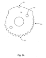
- the ROM disk 34 includes a plurality of spur teeth 62 and a plurality of worm teeth 64 about its perimeter, each lying in a similar plane.
- the spur teeth 62 each geometrically complement, and are selectably engagable with, the one or more slide teeth 48. Engagement of the spur teeth 62 with the slide teeth 48 work to interlock the lock slide 44 with the ROM disk 34 to arrest rotational motion of the lower member 16 relative to the upper member 15 in a direction of flexion, and enables a one-way step-advance ratcheting in a direction from flexion to extension.
- the spur teeth 62 are raked, or inclined, as specifically shown in Figure 6a , to geometrically hold the interlocked spur teeth 62 and the slide teeth 48 together upon knee buckling, as when a user falls back.
- the worm teeth 64 are engagably positioned with the worm gear 50 so that operation of the worm gear 50 (turning the worm gear 50 about its longitudinal axis) incrementally engages worm teeth 64 to rotate the ROM disk 34 about its axis, thereby adjusting a range of motion upon which the elastomeric spring dampening system will operate to cushion weight-bearing shock during walking and to assist leg extension during the swing phase of gait.
- the range of motion is adjustable between approximately 0-30° about the pivot post 40.
- the distal half joint 32 further includes indicating teeth 63 which cooperate with a recess 65 in the ROM disk 34 to provide simple indication of the range of motion set by operation of the worm gear 50.
- indicating teeth 63 which cooperate with a recess 65 in the ROM disk 34 to provide simple indication of the range of motion set by operation of the worm gear 50.
- adjacent alignment of the recess 65 with a certain indicating tooth 63 would provide indication of a certain degree of range of motion set.
- each of four indicating teeth 63 would indicate a 10° change in range of motion (i.e., 0°, 10°, 20°, 30°). This feature is helpful to ensuring that the range of motion set for a lateral hinge assembly 12, for instance, is the same as that set for a corresponding medial hinge assembly 13.
- the spring housing 38 includes two convex, cylindrically shaped channels 66, each channel 66 housing an elastomeric spring 36.
- each elastomeric spring 36 is a cylinder of urethane.
- other elastomeric materials can be employed, such as but not limited to silicon, silicone urethane, nylon, and delrine.
- various elastomeric materials with properties ranging from elastic to inelastic, having varying degrees of rate of return to original shape or hysteresis, might be desired.
- the urethane springs can each be selectively designed, in size, shape and composition, to provide a pre-determined force deflection curve to match desired shock absorption characteristics, and/or to provide a pre-determined hysteresis to alter the rate of return of the elastomeric material to original (i.e., at rest, or no load) shape, to match desired swing assist and cadence characteristics, as discussed below.
- the spring housing 38 includes two radially extending tabs 68, forming a catch 70 therebetween, to receive the lock slide 44 upon full extension of the hinge assembly 14, thereby enabling dampening upon subsequent flexion of the hinge assembly 14, and enabling assistance upon extension.
- the ROM disk 34 includes two spring manipulating posts 72, each housed within a post hole 73 in, and perpendicularly extending from an outer face of, the ROM disk 34. Each spring post 72 is positioned for reception by one of the channels 66 of the spring housing 38, as shown in Figure 5a , and for bearing engagement with an end of a respective elastomeric spring 36.
- the spring housing 38 becomes rotatable relative to the ROM disk 34, so that a subsequent flexion of the hinge assembly 14 causes each spring post 72 to compress a respective elastomeric spring 36 within the respective channel 66, and against the channel 66 and the ROM disk 34.
- flexion of the hinge assembly 14 increases (i.e., the upper member 15 moves toward the lower member 16)
- the portion of the channel 66 housing the respective elastomeric spring 36 decreases in area (due to spring housing 38 movement relative to the spring post 72), causing ever increasing confinement of the respective elastomeric spring 36.
- the elastomeric springs 36 during compression, provide resistance to, or dampening of, flexion of the hinge assembly 14, thereby providing the shock absorption feature of the knee brace 10 upon heel strike and weight bearing transfer during walking. Consequently, removal of weight from the flexed limb results in a decompressive force of the elastomeric springs 38 upon the spring posts 72 of the spring housing 38, which thereby urges, or assists, knee movement during the swing phase of gait from a flexion to an extension position.
- the lock slide 44 is not secured within the catch 70, the flexion restraint and extension assistance features are disengaged, as rotatable movement of the spring housing 38 relative to the ROM disk 34 is avoided.
- the cable release mechanism 20 of associated lock slide assembly 18 includes a lever 74, a cable release housing 75, a toggle cam 76, a cable slide 77, and two cables 78.
- the two cables 78 are each retained within a tube 79, each tube 79 having on its proximal end a housing fitting 80 which cooperates with a threaded terminal 81 on each cable 78 end to retain the cable slide 77 within a recess in the housing 75.
- Each of the two cables 78 operate a respective lock slide assembly 18 (one serving the lateral joint assembly 12 and the other serving the medial joint assembly 13).
- each tube 79 has on its distal end a lock slide end fitting 82 which cooperates with the proximal half joint 30 to terminate the cable release mechanism 20 at the lock slide assembly 18.
- a bulbous cable fitting 83 at a distal end of the cable 78, resides within a circular recess 84 in the lock slide 44.
- the cable 78 passes through the distal biasing spring 85 residing within a spring recess 86 in the proximal half joint 30.
- the lock slide end fitting 82 is nestled and secured within a detent 87 formed within the proximal half joint 30 and the lock slide cover 48 upon attachment of the lock slide cover 48 to the proximal half joint 30.
- the distal biasing spring 85 predisposes the slide teeth 48 of the lock slide 44 into engagement with the spur teeth 62 of the ROM disk 34, or predisposes the lock slide 44 into engagement with the catch 70 of the spring housing 38, depending on the position (flexion or extension) of the lower member 16 (or distal half joint 32) relative to the upper member 15 (or proximal half joint 30). Pulling the cables 78 compresses the distal biasing spring 85 and retracts the lock slide 44, thereby translating the lock slide 44 away from the pivot point and disengaging the lock slide 44 from either the spur teeth 62 of the ROM disk 34 or the catch 70 of the spring housing 38.
- the lower member 16 rotates freely relative to the upper member 15 about the pivot point within a range of approximately 120°.
- the cable release housing 75 is fixedly attached to the upper member with setscrews.
- the lever 74 is fixedly secured to the toggle cam 76 by retaining screw 88.
- the toggle cam 76 is rotatably and translatably housed within the recess in the cable release housing 75, being retained therein by the cable slide 77 biased to retain the toggle cam 76 within the housing 75 by taut cables 78.
- the toggle cam 76 is designed with a projecting cammed surface 90, a first flat surface 91, and a second flat surface 92, the cammed surface 90 bearing against a bottom 75 of the recess in the cable release housing 75.
- the projecting cammed surface 90 bearing against the bottom 75 of the recess in the cable release housing 75, causes the retaining screw 88 and cable slide 77 to translate linearly within the recess of the cable release housing 75 a sufficient distance so that the cables 78 retract the respective lock slides 44, disengaging the lock slides 44 from the respective spring housings 38 or ROM disks 34 of the medial and the lateral hinge assemblies 14.
- the projecting cammed surface 90 incorporates a radius "R" (relative to the pivot point P) greater than that of distances to either of the first or the second flat surfaces 91, 92, which causes a toggle action and snap, under cable tension, when moving from a cammed surface 90 engagement with the bottom 93 to either a first or a second flat surface 91, 92 engagement with the bottom 93, thereby providing a user with a positive and certain positioning (engagement or disengagement) of the lock slide assembly 18 for each of the lateral and medial joint assemblies 12, 13.
- each cable 78 when positioned in retraction, independently exerts a force greater than that of the corresponding distal biasing spring 85 to assure a force necessary to fully disengage the lock slide 44.
- the toggle cam 76 due to the cammed surface 90, linearly translates the cables 78 a distance greater than that necessary to disengage the lock slide 44 from each hinge assembly 14, and does so without over-tensioning the respective cable 78. Additional components that can be employed to assist in preventing cable over-tensioning are detailed later in a description of another embodiment of a cable release mechanism.
- the second flat surface 92 (with distance to the pivot point P greater than that of the first flat surface 91) is adapted to hold the cable in a "proximally pulled” position to hold the lock slide 44 in a fully disengaged position relative to the ROM disk 34 and the spring housing 38.
- the first flat surface 91 (with distance to the pivot point P less than that of the second flat surface 92) is adapted to enable a more distal positioning of the tensioned cables 78, permitting the lock slide 44 to remain in a fully engaged position relative to the ROM disk 34 or the spring housing 38.
- Figures 5a-5e illustrate the hinge assembly 14 of the knee brace 10 in various positions of use, each position employing one or more features of the present invention.
- Figure 5a illustrates the hinge assembly 14 in a position of full flexion, with the angled shoulder 58 of the distal half joint 32 bearing against the rear edge 60 of the proximal half joint 30, the bearing relationship serving as a stop to rotational movement in a flexion direction.
- approximately 60° exist between the upper and the lower members 15, 16. Accordingly, approximately 120° defines a complete range of motion between full flexion and full extension.
- Figure 5a shows the lock slide 44 engaging respective spur teeth 62 of the ROM disk 34, thereby enabling sit-to-stand support, for users having difficulty rising from a sitting position, through one-way, step-advance ratcheting.
- rotational movement toward extension causes the slide teeth 48 to incrementally advance, and ratchet, over the spur teeth 62 of the ROM disk 34.
- This one-way, step advance ratcheting allows controlled knee extension while preventing knee buckling. If a knee begins a flexing movement (i.e., begins buckling) before reaching full extension, the slide teeth 48 engage with and lock into the spur teeth 62. Upon full extension, the slide teeth 48 disengage from, and move out of the vicinity of, the spur teeth 62.
- Figure 5b illustrates the hinge assembly 14 in a position of full extension, with the lock slide 44 secured within the catch 70 of the spring housing 38. Although engaged within the catch 70, the lock slide 44 (as shown in Figure 5b ) still abuts a proximal most spur tooth 94 located about a perimeter of the ROM disk 34.
- the proximal most spur tooth 94 is shown in Figure 5b partially behind a rearmost radially extending tab 68 (rearmost because Figure 5b is a view of a right handed, lateral hinge assembly 14). In this position, at least one slide tooth 48 of the lock slide 44 will bear against the proximal most spur tooth 94 during any attempted movement toward flexion. The hinge assembly 14, therefore, is locked at full extension.
- Figure 5b shows the ROM disk 34 positioned to allow a 0° range of motion, the range of motion being by operation of the worm gear 50.
- the knee is locked at full extension, giving the user stability in stance, a confidence of not falling due to knee buckling, but requiring the user to walk with a stiff knee and consequential strutting gait.
- a 0° range of motion might be used by a stroke patient during early stages of rehabilitation, when confidence and strength may be lacking.
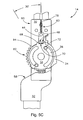
- Figure 5c illustrates the hinge assembly 14 in a position of full extension, the lock slide 44 secured within the catch 70 of the spring housing 38, and the ROM disk 34 positioned to allow a 30° range of motion, as set by operation of the worm gear 50, and as shown by the locational relationship between the proximal most spur tooth 94 and the rearmost radially extending tab 68.
- movement toward flexion causes the spring housing 38 to rotate in conjunction with the proximal half joint 30, about the pivot post 40, and to rotate relative to the ROM disk 34 so that each spring post 72, during movement toward flexion, compresses a respective elastomeric spring 36 within and against the respective channel 66 and against the ROM disk 34.
- Figure 5d illustrates the hinge assembly 14 with the lock slide 44 secured within the catch 70, the ROM disk 34 positioned to allow a 30° range of motion, and the elastomeric spring 36 flexion dampening/extension assisting mechanism engaged.
- Figure 5d shows the hinge assembly 14 reaching a maximum point within the 30° range of motion, at which point the lock slide 44 will abut the proximal most spur tooth 94 to arrest further flexion, and thereby prevent knee buckling and a possible fall if the user's knee were to fail.
- Figure 5d shows the elastomeric springs 36 compressed within respective channels 66 to restrain flexion, to provide dynamic shock absorption at initial contact (i.e.
- a release of weight bearing force to the hinge assembly 14 causes the compressed elastomeric springs 36 to urge the upper and the lower members 15, 16 back toward extension, thereby assisting the user in achieving full terminal swing in the presence of extensor weakness, and to ensure that the heel hits the ground first (rather than the mid or forefoot) at initial strike.
- the elastomeric springs 36 can be varied in size, type, and shape, as discussed below, to provide a wide range of force deflection curves, thereby allowing the present invention to mimic a wide variety of desirable muscle responses, and/or to provide varying restraint of flexion and assistance to extension at different points along the range of motion.
- proximally translating the cable 78 i.e., "raking" up the lever 74
- Disengaging the lock slide 44 permits flexion beyond the 30° range of motion, to a desired sitting position, up to and including a position of full flexion.
- "knuckling" the lever 74 down again engages the lock slide 44 with the ROM disk 34 to again enable the one-way step advance feature, as shown in Figure 5e.
- Figure 5e further shows the ROM disk 34 positioned to allow a 30° range of motion, and the elastomeric springs 36 relaxed, with the flexion dampening/extension assisting mechanism disengaged.
- the elastomeric springs 36 are compressed within the channels 66 by the spring posts 72 of the ROM disk 34.
- the spring posts 72 move within the channels 66, each bearing against one end of an elastomeric spring 36, to translate a non-linear compressing force through the spring 36 beginning at the end.
- the elastomeric cylinders decrease in length and expand in diameter to frictionally embrace the inner walls of the channels 66 and an outer face of the ROM disk 34. Accordingly, varying the properties of the elastomeric springs 36, and/or varying the characteristics of the frictional embrace of the springs 36 to the channels 66 and the ROM disk 34, can control the force deflection and rate of return response of the elastomeric spring 36.
- the outer diameter of the elastomeric springs is less, or slightly less, than an inner diameter of the channels.
- a shape of the inner walls could approximate an exterior of the springs, or could vary to some degree, depending on a deflection response desired.
- the spring diameter must expand to some degree, through compression of length, before the spring will frictionally embrace the inner walls of the channel and the ROM disk.
- the outer diameter of the spring might be substantially equal (in shape and diameter) to the inner wall of the channel, thereby creating a higher coefficient of friction to immediately absorb more energy.
- the elastomeric spring might have a hole bored longitudinally therethrough, the hole affecting expansion of the spring diameter during compression, as the spring material must now expand to fill the hole, the hole thereby consequently affecting the coefficient of friction of the spring.
- the longitudinal hole, and a varying of the diameter of the hole, could be used with either of the spring diameter configurations described above.
- a setscrew or pin is placed in a pre-determined location within the channels to stiffen the dampening response. Since a channel with less surface area (as determined by a position of the setscrew or pin) provides the elastomeric spring less room to expand, the elastomeric spring will become uncompressible sooner, thereby increasing resistance to flexion.
- the cylindrical elastomeric spring 36 is longitudinally segmented with portions of differing durameters, or densities, to vary the restraining force and rate of return over the range of motion of the hinge assembly.
- an elastomeric spring 36 is illustrated having three segments, each segment having a different density to impart a certain desired force deflection curve over a respective portion of the range of motion.
- a first segment 96 may have a relatively low durameter, with corresponding high elasticity, thereby providing a light moment of lesser shock absorption, but providing a rate of return, or extension assistance, typical of a normal swing of gait.
- the second segment 97 may be of moderate durameter, with corresponding moderate elasticity, thereby providing a greater restraining force and shock absorption, but providing a lesser rate of return.
- the third segment 98 might include dense material, of high durameter and low elasticity, thereby enabling absorption of greater force, but providing a slower return and consequently not providing a lot of swing assist.
- the first segment 96 due to its position bearing against the spring post 72, is the first to operate, or acquire compressive forces, during flexion restraint, and the last to operate, or decompress, during extension assistance.
- a material with high elasticity and low durameter may be desirable, to ensure a certain degree of flexion during heel strike and loading response, while providing a high rate of return, or swing assist, to ensure proper heel strike (i.e., to ensure that the heel strikes the ground first) over the final portion, or range, of swing.
- the third segment 98 is the last portion of the elastomeric spring 36 to sustain compressive forces, and offer flexion restraint, over the range of motion during flexion, it may also be desirable to design the third segment 98 of dense material, with high durameter, to provide a high level of shock absorption, or flexion restraint, over this final portion of flexion to avoid a "maxing out" of the joint assembly (i.e., to avoid a complete arresting of flexion upon reaching the maximum range of motion set point (e.g., 30°)) during heel strike and weight transfer.
- the maximum range of motion set point e.g. 30°
- elastomeric materials make elastomeric materials favorable for employment in the present invention.
- greater shock absorption, or flexion restraint, in compression does not necessarily result in an equally great rate of return, or swing assist, in decompression.
- Elastomeric materials return slower, in decompression, than correspondingly respond to a force in compression.
- This characteristic resembles bodily musculature, where, for instance, a quadricep during heel strike and stance absorbs, or resists, a greater force than the quadricep subsequently returns during the swing phase of gait.
- an elastomeric spring of the present invention can be adapted to provide a pre-determined force deflection curve in compression, and an independent rate of return hysteresis in decompression.
- any bodily tissue or muscle can be reproduced, or mimicked, by the present invention.
- muscle performance can be assessed in a laboratory, and a force deflection curve charted.
- an elastomeric spring can be adapted to mimic the charted force deflection curve by selectively determining the necessary size, shape, features, and characteristics of the elastomeric spring.
- FIGs 7a and 7b illustrate a hinge assembly 14a embodiment alternative that shown in Figures 3a and 3b .
- This latter hinge assembly 14a includes many of the same components and functionality of the hinge assembly 14 of Figures 3a and 3b , but does differ in at least a modified spring housing 38 and one additional component, a rotor 100, described as follows.
- the spring housing 38 includes two convex, and cylindrically shaped, channels 66, each channel 66 housing an elastomeric spring 36.
- each elastomeric spring 36 is a cylinder of urethane.
- the rotor 100 rotates about the pivot post 40.
- the rotor 100 includes one or more end teeth 106, and two claws 108.
- the one or more end teeth 106 each geometrically complement, and are selectably engagable with, the one or more slide teeth 48.
- each claw 108 of the rotor 100 When the one or more end teeth 106 are engaged with the one or more slide teeth 48 (which occurs at full extension), rotation of the lower member 16 relative to the upper member 15 toward a flexion position causes each claw 108 of the rotor 100 to bear against a respective elastomeric spring 36 and to compress the spring 36 against its respective and confining channel 66.
- the elastomeric spring 36 during compression, provides resistance to the flexion of the hinge assembly 14a, and the shock absorption feature upon heel strike and weight transfer during walking.
- the hinge assembly 14a of Figures 7a and 7b functionally differs from the hinge assembly 14 of Figures 3a and 3b .
- Adjusting the range of motion (ROM) of hinge assembly 14a, through rotation of the ROM disk 34 via operation of the worm gear 50, does not effect the rotor 100 or spring housing 38 (i.e., the rotor 100 and spring housing 38 remain stationary (unaffected) by ROM adjustment).
- the claws 108 of the rotor 100 are positioned similarly, relative to a respective elastomeric spring 36, just prior to heel strike, regardless of the ROM setting.
- the elastomeric spring 36 may begin (i.e., just prior to heel strike) at rest (i.e., uncompressed), or may begin at various degrees of compression based upon a selected ROM setting (see Figure 5a , where the spring 36 begins compressed with a 0° ROM setting, versus Figure 5c , where the spring 36 begins essentially at rest with a 30° ROM setting).
- This difference in functionality adds to the various spring permutations, discussed above, further enabling achievement of myriad force deflection and hysteresis curves.
- FIG 8 illustrates a cable release mechanism 20a embodiment alternative that shown in Figures 4a and 4b .
- This latter cable release mechanism 20a includes many of the same components and functionality of the cable release mechanism 20 of Figures 4a and 4b , particularly the linearity of cable 78 movement and the camming action, linearly translating the cables 78 a distance greater than that necessary to disengage the lock slide 44, without over-tensioning the respective cable 78, to provide a positive sensory and auditory feedback (snap) upon engagement, thereby ensuring the user that the cam-lock feature is fully actuated in either the engaged (locked) or disengaged (unlocked) position.
- This latter cable release mechanism 20a provides the similar functionality through differing components, or different forms of similar components, described as follows. Further, components are introduced for assisting the prevention of cable over-tensioning. The components, described herein, are equally adaptable for employment with the cable release mechanism 20 of Figures 4a and 4b .
- the cable release mechanism 20a of Figure 8 includes a lever 114, a cable lever housing 116, a cable guide 117, the two cables 78, a proximal terminal 119, a proximal compression spring 120, a locknut 121, a distal terminal 122, the distal biasing spring 85, and the bulbous cable fitting 83.
- the cable lever housing 116 is fixedly attached to the upper member 15 with setscrews.
- the lever 114 is rotatably and translatably attached to the cable lever housing 116 by a binder post 127 through a slot 128 in the cable lever housing 116, the binder post 127 also securing a proximal end of the cables 78, the cables 78 lying and linearly translating within groove 129 of the cable lever housing 116.
- the lever 114 like the toggle cam 76, is designed with a projecting cammed surface 130, a first flat surface 131, and a second flat surface 132, the cammed surface 130 bearing against a proximal end 133 of the upper member 15 when the lever 114 is pivoted about the binder post 127 within the slot 128.
- the projecting cammed surface 130, bearing against the proximal end 133 of the upper member 15, causes the binder post 127 to translate linearly within the slot 128 a sufficient distance so that the cables 78 retract the respective lock slides 44, disengaging the lock slides 44 from the spring housing 38 or the ROM disk 34 of the medial and the lateral hinge assemblies 14, 14a.
- the projecting cammed surface 130 incorporates a radius R (relative to the lever pivot point P) greater than a distance from pivot point P to either the first or the second flat surfaces 131, 132, which causes a toggle action and snap, under cable tension, when moving from a cammed surface 130 engagement with the proximal end 133 to either a first or a second flat surface 131, 132 engagement with the proximal end 133, thereby providing a user with a positive and certain positioning (engagement or disengagement) of the lock slide assembly 18 for each of the lateral and medial hinge assemblies 14, 14a.
- each cable 78 when positioned in retraction, independently exerts a force greater than that of the corresponding distal biasing spring 85 to assure a force necessary to fully disengage the lock slide 44.
- the proximal terminal 119, the proximal compression spring 120, the locknut 121, and the distal terminal 122 enable independent adjustment of cable length and cable tensioning, thereby allowing an independent fine-tuning of each of the respective cable release mechanisms 20a.
- the lever 114 due to the cammed surface 130, linearly translates the cables a distance greater than that necessary to disengage the lock slide 44 from each hinge assembly 14, 14a, and does so without over-tensioning the respective cable 78. Over-tensioning is prevented due to an over-travel allowed by a greater deflection of the proximal compression spring 120.
- the proximal compression spring 120 also serves to tension each cable 78 to hold (bias) one of the first or the second flat surfaces 131, 132 against the proximal end 133 of the upper member 15, thereby providing the user a positive sensory and auditory feedback (snap) upon engagement, and ensuring that the cam-lock feature is fully actuated in either the engaged (locked) or disengaged (unlocked) position.
- the second flat surface 132 (with distance from the pivot point P greater than that of the first flat surface 131) is adapted to hold the cable in a "proximally pulled” position to hold the lock slide 44 in a fully disengaged position relative to the ROM disk 34 and the spring housing 38.
- the proximal compression spring 120 can be adjusted to avoid an over-tensioning of the cable 78 due to the excess travel.
- the first flat surface 131 (with distance from the pivot point P less than that of the second flat surface 132) is adapted to enable a more distal positioning of the tensioned cable 78, first decompressing the proximal compression spring 120, then permitting the lock slide 44 to remain in a fully engaged position relative to the ROM disk 34 or the spring housing 38.
Abstract
Description
- The present invention relates generally to hinge or joint devices as shown in
US 5,409,449 , and more particularly to a hinge or joint assembly for an orthotic, prosthetic, or rehabilitative device capable of supporting the human frame with dynamic shock absorption when walking, while enabling normal, or close to normal, ambulatory motions. - A description of a typical human walking cycle (i.e., gait) begins with a heel strike to the ground, followed by a mid-stance phase in which the front of the foot lowers to the ground, pivoting about the grounded heel. The gait then transitions to a toe-off phase, in which the heel is lifted with an associated forward motion of the leg and body on the ball and toes of the foot. Ultimately, the foot is completely lifted from the ground and swung forward in a swing-through phase to the next heel strike. The other foot undertakes the same cycle of motion in a generally coordinated manner to provide forward locomotion.
- During this complex motion, each knee transitions from a relatively straight extension at heel strike to a rearward bend, or flexion, through the toe-off phase, and returns to extension during the final swing-through phase. During the cycle, the weight of the patient is borne through the knee to varying degrees.
- The human knee system can suffer a number of pathologies that affect the patient's ability to bear this weight and walk (with or without pain). Orthotic knee devices are primarily directed to supporting and stabilizing the knee in response to muscle weakness and/or joint instability. The devices support, guide, and limit the range of motion of the knee joint during the gait cycle. However, traditional orthotic devices are prone to rigidity in movement, and do not provide flexion and extension capabilities approximating that of a healthy, normal knee. For instance, during a normal walking motion, there exists a certain degree of muscle resistance during knee flexion, and a certain degree of shock absorption by the quadriceps, upon heel strike, thereby causing knee flexion and preventing the impact from permeating up the leg to the hips and back, as can occur with a stiff-legged, strutting gait.
- For the foregoing reasons, it is an objective of orthotic devices to provide fundamental support, while additionally providing versatility of motion that, to the greatest extent possible, resembles normal joint and muscle function to absorb ground reaction forces and redirect them toward forward progression. Further, an orthotic device closely approximating normal joint and muscle motion can help prevent a learned disuse of certain muscles and movements during a period of prolonged immobility and/or rehabilitation, whereby the brain settles on compensatory muscle use and movements that greatly inhibit mobility, eventually requiring heavier and more restrictive devices resulting in more noticeable limp and an inefficient gait.
- The present invention provides an orthotic, prosthetic, or rehabilitative device that assists, or takes the place of, muscles that are weak or absent, and that normally control and prevent the knee from lagging during swing-through extension, from buckling at heel strike through terminal stance on the balls and toes of the foot, and from buckling during sit-to-stand from a chair. The device of the present invention provides controlled, multi-position rotational motion in the extension direction to prevent knee buckling from sit-to-stand through a ratcheting, step-advance feature. Further, resistance to knee flexion is provided through an elastomeric spring, enabling a dampening shock absorption feature, the elastomeric spring also assisting knee movement from a flexed attitude during the swing-phase to a straight leg position (extension) just prior to initial contact with the floor (heel strike). Elastomeric material characteristics further enable relatively high stance control moments to be effectively dampened, while swing return moments and rate of return (or hysteresis) are far less in magnitude and velocity, thereby mimicking normal muscle function.
- The present invention provides a weight bearing strut assembly capable of supporting the human frame in the act of walking, while enabling a leg to which it is attached to bend in a normal and natural ambulatory manner. While walking, the present invention provides shock absorption during heel strike and an accelerating or urging capability to a forward moving lower leg during swing from knee flexion to extension in preparation for receiving weight upon heel strike. Both the dampening, shock absorption function and the urging capability or force is adjustable, with a degree of force and angle of rotation upon which the force is provided being adaptable to suit individual needs. The present invention incorporates the normal and natural ambulatory motion with the security of a step-advance feature, ensuring support of the knee during weight bearing extension (e.g., rising from a sitting position). The elastomeric spring can be adapted to reproduce the force deflection curve of any bodily muscle, by varying the size, shape, and/or characteristics of the elastomeric spring.
- The principles and concepts of the present invention can be used in hinge and joint assemblies generally, can be used in an orthotic and/or rehabilitative embodiment as taught and described herein, or can be used in a prosthetic embodiment as modified by those with skill in the art from an appreciation of the present invention. Further, in addition to use in joint and hinge assemblies generally, the present invention can be specifically directed to devices supporting any flexible ligamentous joint, such as the ankle, elbow, or shoulder, and can be adapted to mimicking, assisting, and/or supporting any muscle or tissue, including providing adjustable corrective or therapeutic force for the reduction of joint and muscle stiffness, contracture, or for management of spasficity.
- According to the invention defined in claim 1, the hinge assembly includes a first member movably connected to a second member to allow angular displacement of the first member relative to the second member between extension and flexion positions, and at least one elastomeric spring communicating with the first and the second members to restrain angular displacement from an extension to a flexion position, or from a flexion to an extension position, through compression of the at least one elastomeric spring, and to assist angular displacement from a flexion to an extension position, or from an extension to a flexion position, through decompression of the at least one elastomeric spring. The elastomeric spring can be adapted to provide a pre-determined force deflection curve in compression and an independent rate of return hysteresis in decompression. The elastomeric spring could be a urethane spring.
- Further embodiments are defined in the dependant claims.
- The foregoing summary, as well as the following detailed description of the invention, will be better understood when read in conjunction with the appended drawings. For the purpose of illustrating the invention, there are shown in the drawings certain embodiments of the present inventions. It should be understood, however, that the invention is not limited to the precise arrangements and instrumentalities shown. In the drawings, the same reference numerals are employed for designating the same elements throughout the several figures. In the drawings:
-
Figure 1 illustrates an orthotic knee brace for the right leg in accordance with one embodiment of the present invention; -
Figure 2 illustrates a lateral, right-hand hinge assembly with cable release mechanism, and accompanying lateral struts, of the knee brace ofFigure 1 ; -
Figure 3a illustrates an overhead, or front-side, perspective, exploded view of a lateral, left-hand hinge assembly in accordance with one embodiment of the present invention; -
Figure 3b illustrates an underside, perspective, exploded view of the hinge assembly ofFigure 3a ; -
Figure 4a illustrates a front-side, perspective, exploded view of a cable release mechanism in accordance with one embodiment of the present invention; -
Figure 4b illustrates a back, or underside, perspective, exploded view of the cable release mechanism ofFigure 4a ; -
Figure 5a illustrates a front elevation view of the hinge assembly ofFigure 1 in a position of full flexion, with slide teeth of a lock slide engaging spur teeth of a range of motion (ROM) disk to provide one-way, step advance ratcheting of rotational movement toward extension,Figure 5a also illustrating the ROM disk set for a 30° range of motion, with elastomeric springs partially compressed (providing pre-load) due to spring post positioning within respective channels; -
Figure 5b illustrates a front elevation view of the hinge assembly ofFigure 1 in a position of full extension, with the slide teeth engaging a catch in a spring housing and the ROM disk set for a 0° range of motion (i.e., the slide teeth abut a proximal most spur tooth of the ROM disk, the abutment arresting rotational movement toward flexion); -
Figure 5c illustrates a front elevation view of the hinge assembly ofFigure 1 in a position of full extension, with the slide teeth engaging the catch in the spring housing and the ROM disk set for a 30° range of motion, thereby enabling, within the 30° range of motion, a dampening of rotation toward flexion and an urging of rotation toward extension; -
Figure 5d illustrates a front elevation view of the hinge assembly ofFigure 1 in a position maximizing the 30° range of motion,Figure 5d showing springs compressed and dampening the rotation toward flexion; -
Figure 5e illustrates a front elevation view of the hinge assembly ofFigure 1 in a position of full flexion, with the slide teeth again engaging the spur teeth to provide one-way, step advance ratcheting of rotational movement toward extension,Figure 5e also illustrating the ROM disk set for a 30° range of motion, with elastomeric springs at rest (no pre-load) due to spring post positioning within the respective channels; -
Figure 6a illustrates the ROM disk of the previous figures, showing worm teeth and the spur teeth located about a perimeter of the ROM disk in a similar plane,Figure 6a also showing two holes adapted to accept the spring posts; -
Figure 6b illustrates one embodiment of an elastomeric spring in accordance with the present invention; -
Figure 7a illustrates an overhead, or front-side, perspective, exploded view of a lateral, left-hand alternative hinge assembly in accordance with another embodiment of the present invention; -
Figure 7b illustrates an underside, perspective, exploded view of the hinge assembly ofFigure 7a ; -
Figure 8 illustrates a front-side, perspective, exploded view of an alternative cable release mechanism in accordance with another embodiment of the present invention; - The present invention is a joint or hinge assembly generally, and more particularly an ambulating knee joint having several embodiments, functioning to address various problems while offering advantageous rehabilitative capabilities. Embodiments of the present invention include one or more of the following features:
- ■ dynamic shock absorption at initial contact (i.e. heel strike) to dampen ground reaction forces and loading responses, for smoother knee flexion during gait;
- ■ swing assist to achieve full terminal swing in the presence of extensor weakness, thereby ensuring that the heel hits the ground first (rather than the mid or forefoot);
- ■ sit-to-stand support from a chair, for those having difficulty rising from a sitting position, through a one-way, step-advance ratchet from full flexion (approximately 120° flexion) to full extension, that allows knee extension but prevents knee buckling by locking if the knee begins flexion before reaching a standing position;
- ■ an adjustable range of motion, adjustable between typical flexion angles experienced during stance phase of gait (e.g., between 0-30° in current exemplary use), the adjustable range of motion defining an operating range for the variably controlled knee flexion (without knee locking) and extension during walking or standing through use of a range of motion (ROM) disc adjusted by a worm gear, the ROM disc allowing knee flexion, but also arresting flexion if the knee buckles (e.g., due to weak quadriceps) beyond the set point of the range of motion, arresting flexion thereby preventing a fall;
- ■ an elastomeric spring providing variable force deflection curves to mimic desirable muscle responses, providing variable restraint of flexion and assisting extension at various angles of flexion and extension; and
- ■ a lever lock employing a toggle cam to engage and disengage the sit-to-stand, one-way, step-advance ratchet support, the 0-30° controlled knee flexion/extension with elastomeric spring shock absorption and swing assist, and a release enabling free-rotation (a ROM disc override) for sitting, the lever adapted for easy "pushing" by the knuckles or "raking" by the clawed fingers of an impaired hand (e.g., by stroke), the "pushing" and "raking" requiring little finger force, sensation or dexterity as gross elbow movement is employed, the clawed fingers remaining in a natural resting position, the toggle and cam providing visual, sensory and auditory feedback that the lock is properly engaged or disengaged, the lever assembly being low profile for actuation under clothing. The toggle cam also provides fine adjustment to properly tension cable release for engagement and disengagement.
- The present invention can be used in any joint or hinge assembly, particularly those benefiting from a dampening and/or resisting of two members angularly moving closer to one another, and an urging and/or assisting of the two members angularly extending away from one another. Further, the present application has applicability in any muscle adaptation system, such as in robotics, as the elastomeric spring can be adapted to mimic any bodily tissue and/or musculature. Additionally, any flexible ligamentous joint can be supported and assisted (orthotics), rehabilitated, or replaced (prosthetics) with an adaptation of the present invention.
- More particularly, in one embodiment the present invention satisfies the rehabilitation needs of a stroke patient. Stroke patients often suffer a partial, temporary, or permanent paralysis to one side of the body. Accordingly, muscle strength, control, and coordination are reduced. During rehabilitation, the patient is encouraged to walk as much as possible to re-train, control and re-strengthen the muscles, and to stimulate the neuro-plasticity of the brain to re-learn to walk. Patients often lack the necessary confidence and strength to walk without falling; such a patient could be fitted with an orthotic knee brace employing an embodiment of the present invention.
- In this embodiment, the joint would likely be set, initially, with a 0° range of motion. As such, the knee is locked in full extension, giving the patient stability in stance, and a confidence that they will not fall due to knee buckling. As rehabilitation progresses some range of motion would be allowed, and then would be incrementally increased as the hinge assembly of the present invention can be adjusted to enable between 0-30° of flexion in infinite degree increments. Incrementally increasing the range of motion during rehabilitation enables a re-development of a normal gait, while still offering support if the knee fails to prevent knee buckling.
- In another embodiment, and perhaps in the orthotic embodiment above, an extension moment at the knee assists the limb in the swing-phase of gait, thereby helping the knee reach full extension for muscle reeducation, strengthening, and cortical retraining. This embodiment could further include restraint of flexion, providing dynamic shock absorption at initial contact (i.e. heel strike) to dampen ground reaction forces and loading responses for smoother knee flexion during gait, such as in forced limb use programs, stroke rehabilitation, and in any permanent extensor weakness causing knee instability and buckling.
- Other potential uses for the brace include any condition (neurological or orthopedic), which weakened the extensor mechanisms, preventing the patient from reaching full extension during walking or causing knee buckling during stance when the limb bears weight.
- The joint can be mounted either on a traditional metal and leather KAFO, or a molded plastic or composite brace. Mounts could accommodate 3/4 x 3/16 or 3/4 x 1/4 in aluminum or stainless steel uprights, or some other type of connector to be used with composite or molded brace construction.
- One embodiment of the invention incorporates a hinge assembly into an ambulating knee joint having an elastomeric spring dampening system that cushions weight-bearing shock during walking, dampening flexion, and assists leg extension during the swing-phase of gait. The dampening and swing assist moments operate within a range of motion as provided by a range of motion (ROM) disk and determined by an adjustable worm gear mechanism. In this embodiment, the range of motion can be set between 0° and 30°, adjustable therein depending on the strength and needs of the patient (i.e., as the patient becomes stronger, less support is needed, and the range of motion can usually be increased). The dampening and swing assist forces within this range of motion can also be adjusted to individual needs to sufficiently provide a moment at each swing through phase of gait and to provide shock absorption for smoother walking by redirecting forces toward forward progression to reduce an energy cost of walking for the patient.
- Please note that although the following exemplary embodiments illustrate angular displacement of a first, or proximal, member relative to a second, or distal, member about a pivot point, and illustrate angular movement capability of other components (e.g., a disk, a spring assembly) about the same pivot point, the present invention is not limited to such structure. The present invention includes, and features of the present invention are applicable to, hinge assembly angular articulation about instance centers, eccentric surfaces, polycentric and multicentric axes, a plurality of camming surfaces, etc.
- Further, the exemplary embodiments detailed below illustrate a dampening of angular displacement, or articulation, in a direction of flexion, and an urging of angular displacement in a direction of extension. The present invention is also not limited to such directional requirements, the present invention contemplating dampening and assisting in any direction. Accordingly, the present invention further includes, and features of the present invention are applicable to, a dampening, restricting, or restraining of angular displacement from a flexion to an extension position, and/or an assisting, or urging, of angular displacement from an extension to a flexion position.
-
Figure 1 illustrates anorthotic knee brace 10 adapted for a right leg ("right hand"), theknee brace 10 incorporating one embodiment of the joint or hinge assembly of the present invention. Theknee brace 10 includes right hand lateraljoint assembly 12 and a right hand medialjoint assembly 13. The joint assemblies function similarly, whether right hand lateral, right hand medial, left hand lateral, or left hand medial, the differences simply being orientation of the respective device relative to its position, particularly effected is the orientation of a distal half joint (described below). -
Figure 2 illustrates the right hand lateraljoint assembly 12 of theorthotic knee brace 10. Thejoint assembly 12 includes ahinge assembly 14, a proximal strut, orupper member 15, a distal strut, orlower member 16, alock slide assembly 18 with associatedcable release mechanism 20. -
Figures 3a and3b are exploded views of thehinge assembly 14,Figure 3a being a top, or front side perspective exploded view,Figure 3b being a bottom, or underside perspective exploded view. Further, the exploded views ofFigures 3a and3b actually illustrate a left hand lateral hinge assembly. Thehinge assembly 14 includes a proximal half joint 30, fixedly attached to theupper member 15 withscrews 31, a distal half joint 32, fixedly attached to thelower member 16 withscrews 33, a range of motion (ROM)disk 34, elastomeric springs 36, and aspring housing 38.Certain hinge assembly 14 components are rotatably secured to one another by apivot post 40 and abreak pin 42, with various washers interleaved between the components to facilitate rotational movement, provide wear resistance, remove tolerance build up in thicknesses and length of thepivot post 40 andbreak pin 42. Anaesthetic cover 43 fits within a recess in thespring housing 38 to cover thebreak pin 42 and access to hinge disassembly. - The proximal half joint 30 houses components of the
lock slide assembly 18, thelock slide assembly 18 enabling a rotational step-advance feature when thehinge assembly 14 pivots from a flexion to an extension position. Alock slide 44 is translatably housed within arectangular recess 46 in the proximal half joint 30 and secured therein by alock slide cover 47. Thelock slide 44 translates linearly within therectangular recess 46 through a center-line directed toward and through a pivot point of thehinge assembly 14, the pivot point defined by thepivot post 40 and generally by a center of circular portions of thehinge assembly 14 components. Thelock slide 44 includes, at its distal end, one ormore slide teeth 48. - The distal half joint 32 houses a
worm gear 50, rotatably attached to the distal half joint 32 by aworm gear screw 52. Theworm gear 50 interlocks with theworm gear screw 52, so that axial rotation of theworm gear screw 52 translates axial rotation to theworm gear 50. - The proximal half joint 30 includes, on its underside, a projecting tab, or stop 54 (the stop lies on a center-line projecting toward the pivot point of the hinge assembly 14). The
stop 54 cooperates with atab 56 radially extending from a perimeter of a circular portion of the distal half joint 32. Thestop 54 bears against, or interlocks with, theradially extending tab 56 to prevent hyperextension of the knee when pivoting from a flexion to extension positions (i.e., thestop 54 interlocks with, or bears against, theradially extending tab 56 when the upper member is 180° relative to the lower member). The distal half joint 32 includes anangled shoulder 58 that aligns with, and bears against, arear edge 60 of the proximal half joint 30, serving as a stop to rotational movement in a flexion direction, and thereby defining a maximum extent of flexion for thehinge assembly 14, occurring when approximately 60° exists between the upper and thelower members - The
ROM disk 34 includes a plurality ofspur teeth 62 and a plurality ofworm teeth 64 about its perimeter, each lying in a similar plane. Thespur teeth 62 each geometrically complement, and are selectably engagable with, the one ormore slide teeth 48. Engagement of thespur teeth 62 with theslide teeth 48 work to interlock thelock slide 44 with theROM disk 34 to arrest rotational motion of thelower member 16 relative to theupper member 15 in a direction of flexion, and enables a one-way step-advance ratcheting in a direction from flexion to extension. Thespur teeth 62 are raked, or inclined, as specifically shown inFigure 6a , to geometrically hold the interlockedspur teeth 62 and theslide teeth 48 together upon knee buckling, as when a user falls back. The weight of a user falling back, causing rotation toward flexion, ramps thespur teeth 62 and theslide teeth 48 together. Due to the incline of the respective teeth, the weight of the user acts to further interlock the geometrically complementing teeth due to the angle of incline. - The
worm teeth 64 are engagably positioned with theworm gear 50 so that operation of the worm gear 50 (turning theworm gear 50 about its longitudinal axis) incrementally engagesworm teeth 64 to rotate theROM disk 34 about its axis, thereby adjusting a range of motion upon which the elastomeric spring dampening system will operate to cushion weight-bearing shock during walking and to assist leg extension during the swing phase of gait. In this embodiment, the range of motion is adjustable between approximately 0-30° about thepivot post 40. - The distal half joint 32 further includes indicating
teeth 63 which cooperate with arecess 65 in theROM disk 34 to provide simple indication of the range of motion set by operation of theworm gear 50. As theROM disk 34 rotates about thepivot post 40, by operation of theworm gear 50, to adjust the range of motion, adjacent alignment of therecess 65 with a certain indicatingtooth 63 would provide indication of a certain degree of range of motion set. For instance, in the embodiment shown inFigures 3a and3b , each of four indicatingteeth 63 would indicate a 10° change in range of motion (i.e., 0°, 10°, 20°, 30°). This feature is helpful to ensuring that the range of motion set for alateral hinge assembly 12, for instance, is the same as that set for a correspondingmedial hinge assembly 13. - The
spring housing 38 includes two convex, cylindrically shapedchannels 66, eachchannel 66 housing anelastomeric spring 36. In this embodiment, eachelastomeric spring 36 is a cylinder of urethane. However, other elastomeric materials can be employed, such as but not limited to silicon, silicone urethane, nylon, and delrine. Depending on the dampening and urging application, various elastomeric materials, with properties ranging from elastic to inelastic, having varying degrees of rate of return to original shape or hysteresis, might be desired. The urethane springs can each be selectively designed, in size, shape and composition, to provide a pre-determined force deflection curve to match desired shock absorption characteristics, and/or to provide a pre-determined hysteresis to alter the rate of return of the elastomeric material to original (i.e., at rest, or no load) shape, to match desired swing assist and cadence characteristics, as discussed below. - The
spring housing 38 includes two radially extendingtabs 68, forming acatch 70 therebetween, to receive thelock slide 44 upon full extension of thehinge assembly 14, thereby enabling dampening upon subsequent flexion of thehinge assembly 14, and enabling assistance upon extension. TheROM disk 34 includes twospring manipulating posts 72, each housed within apost hole 73 in, and perpendicularly extending from an outer face of, theROM disk 34. Eachspring post 72 is positioned for reception by one of thechannels 66 of thespring housing 38, as shown inFigure 5a , and for bearing engagement with an end of a respectiveelastomeric spring 36. When thelock slide 44 is secured within thecatch 70, thespring housing 38 becomes rotatable relative to theROM disk 34, so that a subsequent flexion of thehinge assembly 14 causes eachspring post 72 to compress a respectiveelastomeric spring 36 within therespective channel 66, and against thechannel 66 and theROM disk 34. As flexion of thehinge assembly 14 increases (i.e., theupper member 15 moves toward the lower member 16), the portion of thechannel 66 housing the respectiveelastomeric spring 36 decreases in area (due tospring housing 38 movement relative to the spring post 72), causing ever increasing confinement of the respectiveelastomeric spring 36. The elastomeric springs 36, during compression, provide resistance to, or dampening of, flexion of thehinge assembly 14, thereby providing the shock absorption feature of theknee brace 10 upon heel strike and weight bearing transfer during walking. Consequently, removal of weight from the flexed limb results in a decompressive force of the elastomeric springs 38 upon the spring posts 72 of thespring housing 38, which thereby urges, or assists, knee movement during the swing phase of gait from a flexion to an extension position. When thelock slide 44 is not secured within thecatch 70, the flexion restraint and extension assistance features are disengaged, as rotatable movement of thespring housing 38 relative to theROM disk 34 is avoided. - Referring now to
Figures 4a and4b , thecable release mechanism 20 of associatedlock slide assembly 18 includes alever 74, acable release housing 75, atoggle cam 76, acable slide 77, and twocables 78. The twocables 78 are each retained within atube 79, eachtube 79 having on its proximal end a housing fitting 80 which cooperates with a threadedterminal 81 on eachcable 78 end to retain thecable slide 77 within a recess in thehousing 75. Each of the twocables 78 operate a respective lock slide assembly 18 (one serving the lateraljoint assembly 12 and the other serving the medial joint assembly 13). - Referring now to
Figures 3a ,4a , and4b , eachtube 79 has on its distal end a lock slide end fitting 82 which cooperates with the proximal half joint 30 to terminate thecable release mechanism 20 at thelock slide assembly 18. A bulbous cable fitting 83, at a distal end of thecable 78, resides within acircular recess 84 in thelock slide 44. Thecable 78 passes through thedistal biasing spring 85 residing within aspring recess 86 in the proximal half joint 30. The lock slide end fitting 82 is nestled and secured within adetent 87 formed within the proximal half joint 30 and thelock slide cover 48 upon attachment of thelock slide cover 48 to the proximal half joint 30. Thedistal biasing spring 85 predisposes theslide teeth 48 of thelock slide 44 into engagement with thespur teeth 62 of theROM disk 34, or predisposes thelock slide 44 into engagement with thecatch 70 of thespring housing 38, depending on the position (flexion or extension) of the lower member 16 (or distal half joint 32) relative to the upper member 15 (or proximal half joint 30). Pulling thecables 78 compresses thedistal biasing spring 85 and retracts thelock slide 44, thereby translating thelock slide 44 away from the pivot point and disengaging thelock slide 44 from either thespur teeth 62 of theROM disk 34 or thecatch 70 of thespring housing 38. When thelock slide 44 is disengaged from thespring housing 38 and theROM disk 34, thelower member 16 rotates freely relative to theupper member 15 about the pivot point within a range of approximately 120°. - Referring now to
Figures 2 ,4a , and4b , at a proximal end of theupper member 15, thecable release housing 75 is fixedly attached to the upper member with setscrews. Thelever 74 is fixedly secured to thetoggle cam 76 by retaining screw 88. Thetoggle cam 76 is rotatably and translatably housed within the recess in thecable release housing 75, being retained therein by thecable slide 77 biased to retain thetoggle cam 76 within thehousing 75 bytaut cables 78. - The
toggle cam 76 is designed with a projectingcammed surface 90, a firstflat surface 91, and a secondflat surface 92, thecammed surface 90 bearing against a bottom 75 of the recess in thecable release housing 75. When thelever 74 is pivoted about the retaining screw 88 (at pivot point "P"). The projectingcammed surface 90, bearing against the bottom 75 of the recess in thecable release housing 75, causes the retaining screw 88 andcable slide 77 to translate linearly within the recess of the cable release housing 75 a sufficient distance so that thecables 78 retract the respective lock slides 44, disengaging the lock slides 44 from therespective spring housings 38 orROM disks 34 of the medial and thelateral hinge assemblies 14. The projectingcammed surface 90 incorporates a radius "R" (relative to the pivot point P) greater than that of distances to either of the first or the secondflat surfaces cammed surface 90 engagement with the bottom 93 to either a first or a secondflat surface lock slide assembly 18 for each of the lateral and medialjoint assemblies - Accordingly, each
cable 78, when positioned in retraction, independently exerts a force greater than that of the corresponding distal biasingspring 85 to assure a force necessary to fully disengage thelock slide 44. Thetoggle cam 76, due to thecammed surface 90, linearly translates the cables 78 a distance greater than that necessary to disengage thelock slide 44 from eachhinge assembly 14, and does so without over-tensioning therespective cable 78. Additional components that can be employed to assist in preventing cable over-tensioning are detailed later in a description of another embodiment of a cable release mechanism. - When the
lever 74 is "raked" up (as shown inFigures 4a and4b ), the second flat surface 92 (with distance to the pivot point P greater than that of the first flat surface 91) is adapted to hold the cable in a "proximally pulled" position to hold thelock slide 44 in a fully disengaged position relative to theROM disk 34 and thespring housing 38. When thelever 74 is "knuckled" down, relative to the patient, the first flat surface 91 (with distance to the pivot point P less than that of the second flat surface 92) is adapted to enable a more distal positioning of the tensionedcables 78, permitting thelock slide 44 to remain in a fully engaged position relative to theROM disk 34 or thespring housing 38. -
Figures 5a-5e illustrate thehinge assembly 14 of theknee brace 10 in various positions of use, each position employing one or more features of the present invention.Figure 5a illustrates thehinge assembly 14 in a position of full flexion, with theangled shoulder 58 of the distal half joint 32 bearing against therear edge 60 of the proximal half joint 30, the bearing relationship serving as a stop to rotational movement in a flexion direction. At full flexion, approximately 60° exist between the upper and thelower members -
Figure 5a shows thelock slide 44 engagingrespective spur teeth 62 of theROM disk 34, thereby enabling sit-to-stand support, for users having difficulty rising from a sitting position, through one-way, step-advance ratcheting. As shown inFigure 5a , rotational movement toward extension causes theslide teeth 48 to incrementally advance, and ratchet, over thespur teeth 62 of theROM disk 34. This one-way, step advance ratcheting allows controlled knee extension while preventing knee buckling. If a knee begins a flexing movement (i.e., begins buckling) before reaching full extension, theslide teeth 48 engage with and lock into thespur teeth 62. Upon full extension, theslide teeth 48 disengage from, and move out of the vicinity of, thespur teeth 62. -
Figure 5b illustrates thehinge assembly 14 in a position of full extension, with thelock slide 44 secured within thecatch 70 of thespring housing 38. Although engaged within thecatch 70, the lock slide 44 (as shown inFigure 5b ) still abuts a proximalmost spur tooth 94 located about a perimeter of theROM disk 34. The proximalmost spur tooth 94 is shown inFigure 5b partially behind a rearmost radially extending tab 68 (rearmost becauseFigure 5b is a view of a right handed, lateral hinge assembly 14). In this position, at least oneslide tooth 48 of thelock slide 44 will bear against the proximalmost spur tooth 94 during any attempted movement toward flexion. Thehinge assembly 14, therefore, is locked at full extension. Accordingly,Figure 5b shows theROM disk 34 positioned to allow a 0° range of motion, the range of motion being by operation of theworm gear 50. As such, the knee is locked at full extension, giving the user stability in stance, a confidence of not falling due to knee buckling, but requiring the user to walk with a stiff knee and consequential strutting gait. A 0° range of motion might be used by a stroke patient during early stages of rehabilitation, when confidence and strength may be lacking. -
Figure 5c illustrates thehinge assembly 14 in a position of full extension, thelock slide 44 secured within thecatch 70 of thespring housing 38, and theROM disk 34 positioned to allow a 30° range of motion, as set by operation of theworm gear 50, and as shown by the locational relationship between the proximalmost spur tooth 94 and the rearmost radially extendingtab 68. Within the 30° range of motion, with thelock slide 44 secured within thecatch 70, movement toward flexion causes thespring housing 38 to rotate in conjunction with the proximal half joint 30, about thepivot post 40, and to rotate relative to theROM disk 34 so that eachspring post 72, during movement toward flexion, compresses a respectiveelastomeric spring 36 within and against therespective channel 66 and against theROM disk 34. -
Figure 5d illustrates thehinge assembly 14 with thelock slide 44 secured within thecatch 70, theROM disk 34 positioned to allow a 30° range of motion, and theelastomeric spring 36 flexion dampening/extension assisting mechanism engaged.Figure 5d shows thehinge assembly 14 reaching a maximum point within the 30° range of motion, at which point thelock slide 44 will abut the proximalmost spur tooth 94 to arrest further flexion, and thereby prevent knee buckling and a possible fall if the user's knee were to fail.Figure 5d shows the elastomeric springs 36 compressed withinrespective channels 66 to restrain flexion, to provide dynamic shock absorption at initial contact (i.e. at heel strike through midstance), and to dampen ground reaction forces and loading responses to redirect forces to propel forward progression for greater efficiency for smoother knee flexion during gait. Thereafter, a release of weight bearing force to thehinge assembly 14 causes the compressed elastomeric springs 36 to urge the upper and thelower members - At any point during operation, proximally translating the cable 78 (i.e., "raking" up the lever 74) disengages the
lock slide 44 from thespring housing 38 to allow free rotation of theupper member 15 relative to thelower member 16. Disengaging thelock slide 44 permits flexion beyond the 30° range of motion, to a desired sitting position, up to and including a position of full flexion. At full flexion, "knuckling" thelever 74 down again engages thelock slide 44 with theROM disk 34 to again enable the one-way step advance feature, as shown inFigure 5e. Figure 5e further shows theROM disk 34 positioned to allow a 30° range of motion, and the elastomeric springs 36 relaxed, with the flexion dampening/extension assisting mechanism disengaged. - The elastomeric springs 36 are compressed within the
channels 66 by the spring posts 72 of theROM disk 34. The spring posts 72 move within thechannels 66, each bearing against one end of anelastomeric spring 36, to translate a non-linear compressing force through thespring 36 beginning at the end. Upon compression, the elastomeric cylinders decrease in length and expand in diameter to frictionally embrace the inner walls of thechannels 66 and an outer face of theROM disk 34. Accordingly, varying the properties of the elastomeric springs 36, and/or varying the characteristics of the frictional embrace of thesprings 36 to thechannels 66 and theROM disk 34, can control the force deflection and rate of return response of theelastomeric spring 36. - In one embodiment, the outer diameter of the elastomeric springs is less, or slightly less, than an inner diameter of the channels. In this embodiment, a shape of the inner walls could approximate an exterior of the springs, or could vary to some degree, depending on a deflection response desired. In either case, in this embodiment, the spring diameter must expand to some degree, through compression of length, before the spring will frictionally embrace the inner walls of the channel and the ROM disk. In another embodiment, the outer diameter of the spring might be substantially equal (in shape and diameter) to the inner wall of the channel, thereby creating a higher coefficient of friction to immediately absorb more energy.
- In another embodiment, the elastomeric spring might have a hole bored longitudinally therethrough, the hole affecting expansion of the spring diameter during compression, as the spring material must now expand to fill the hole, the hole thereby consequently affecting the coefficient of friction of the spring. The longitudinal hole, and a varying of the diameter of the hole, could be used with either of the spring diameter configurations described above.
- In another embodiment, a setscrew or pin is placed in a pre-determined location within the channels to stiffen the dampening response. Since a channel with less surface area (as determined by a position of the setscrew or pin) provides the elastomeric spring less room to expand, the elastomeric spring will become uncompressible sooner, thereby increasing resistance to flexion.
- In another embodiment, the cylindrical
elastomeric spring 36 is longitudinally segmented with portions of differing durameters, or densities, to vary the restraining force and rate of return over the range of motion of the hinge assembly. Referring now toFigure 6b , anelastomeric spring 36 is illustrated having three segments, each segment having a different density to impart a certain desired force deflection curve over a respective portion of the range of motion. For example, afirst segment 96 may have a relatively low durameter, with corresponding high elasticity, thereby providing a light moment of lesser shock absorption, but providing a rate of return, or extension assistance, typical of a normal swing of gait. Thesecond segment 97 may be of moderate durameter, with corresponding moderate elasticity, thereby providing a greater restraining force and shock absorption, but providing a lesser rate of return. Thethird segment 98 might include dense material, of high durameter and low elasticity, thereby enabling absorption of greater force, but providing a slower return and consequently not providing a lot of swing assist. - In the above-segmented embodiment of the
elastomeric spring 96, thefirst segment 96, due to its position bearing against thespring post 72, is the first to operate, or acquire compressive forces, during flexion restraint, and the last to operate, or decompress, during extension assistance. For this reason, a material with high elasticity and low durameter may be desirable, to ensure a certain degree of flexion during heel strike and loading response, while providing a high rate of return, or swing assist, to ensure proper heel strike (i.e., to ensure that the heel strikes the ground first) over the final portion, or range, of swing. Since thethird segment 98 is the last portion of theelastomeric spring 36 to sustain compressive forces, and offer flexion restraint, over the range of motion during flexion, it may also be desirable to design thethird segment 98 of dense material, with high durameter, to provide a high level of shock absorption, or flexion restraint, over this final portion of flexion to avoid a "maxing out" of the joint assembly (i.e., to avoid a complete arresting of flexion upon reaching the maximum range of motion set point (e.g., 30°)) during heel strike and weight transfer. - The hysteresis characteristic of elastomeric materials makes elastomeric materials favorable for employment in the present invention. With elastomeric materials, greater shock absorption, or flexion restraint, in compression does not necessarily result in an equally great rate of return, or swing assist, in decompression. Elastomeric materials return slower, in decompression, than correspondingly respond to a force in compression. This characteristic resembles bodily musculature, where, for instance, a quadricep during heel strike and stance absorbs, or resists, a greater force than the quadricep subsequently returns during the swing phase of gait. This feature makes elastomeric springs advantageous to torsion springs, which return quickly, where a spring loaded to absorb a significant force will subsequently return with swing assist far exceeding that needed or desired by a user. Accordingly, a time rate of compression of an elastomeric spring in response to a certain force is faster than a subsequent time rate of decompression of the elastomeric spring resulting from the certain force. Further, as a result, an elastomeric spring of the present invention can be adapted to provide a pre-determined force deflection curve in compression, and an independent rate of return hysteresis in decompression.
- The above-referenced alternatives and aspects of the elastomeric springs provide many characteristic permutations, the various permutations enabling the achievement of myriad force deflection and hysteresis curves. Accordingly, any bodily tissue or muscle can be reproduced, or mimicked, by the present invention. For instance, muscle performance can be assessed in a laboratory, and a force deflection curve charted. Then, an elastomeric spring can be adapted to mimic the charted force deflection curve by selectively determining the necessary size, shape, features, and characteristics of the elastomeric spring.
-
Figures 7a and7b illustrate ahinge assembly 14a embodiment alternative that shown inFigures 3a and3b . Thislatter hinge assembly 14a includes many of the same components and functionality of thehinge assembly 14 ofFigures 3a and3b , but does differ in at least a modifiedspring housing 38 and one additional component, arotor 100, described as follows. - The
spring housing 38 includes two convex, and cylindrically shaped,channels 66, eachchannel 66 housing anelastomeric spring 36. In this embodiment, eachelastomeric spring 36 is a cylinder of urethane. Adjacent to each of thechannels 66, within thespring housing 38, is arecess 102 centered about a hole 104 (through which thepivot post 40 extends) that houses therotor 100. Within therecess 102, therotor 100 rotates about thepivot post 40. Therotor 100 includes one ormore end teeth 106, and twoclaws 108. The one ormore end teeth 106, each geometrically complement, and are selectably engagable with, the one ormore slide teeth 48. When the one ormore end teeth 106 are engaged with the one or more slide teeth 48 (which occurs at full extension), rotation of thelower member 16 relative to theupper member 15 toward a flexion position causes eachclaw 108 of therotor 100 to bear against a respectiveelastomeric spring 36 and to compress thespring 36 against its respective and confiningchannel 66. Theelastomeric spring 36, during compression, provides resistance to the flexion of thehinge assembly 14a, and the shock absorption feature upon heel strike and weight transfer during walking. Consequently, removal of weight from a respective flexed limb results in a decompressive force of the elastomeric springs 36 upon theclaws 108 of therotor 100, which thereby urges, or assists, knee movement during the swing phase of gait from a flexion to an extension position. - Regarding the force deflection curve provided by the elastomeric springs 36, the
hinge assembly 14a ofFigures 7a and7b functionally differs from thehinge assembly 14 ofFigures 3a and3b . Adjusting the range of motion (ROM) ofhinge assembly 14a, through rotation of theROM disk 34 via operation of theworm gear 50, does not effect therotor 100 or spring housing 38 (i.e., therotor 100 andspring housing 38 remain stationary (unaffected) by ROM adjustment). Accordingly, theclaws 108 of therotor 100 are positioned similarly, relative to a respectiveelastomeric spring 36, just prior to heel strike, regardless of the ROM setting. - Contrast the
hinge assembly 14 ofFigures 3a and3b , where the spring posts 72, connected to theROM disk 34, rotate along with theROM disk 34 during a change to ROM setting. Accordingly, theelastomeric spring 36 may begin (i.e., just prior to heel strike) at rest (i.e., uncompressed), or may begin at various degrees of compression based upon a selected ROM setting (seeFigure 5a , where thespring 36 begins compressed with a 0° ROM setting, versusFigure 5c , where thespring 36 begins essentially at rest with a 30° ROM setting). This difference in functionality adds to the various spring permutations, discussed above, further enabling achievement of myriad force deflection and hysteresis curves. -
Figure 8 illustrates acable release mechanism 20a embodiment alternative that shown inFigures 4a and4b . This lattercable release mechanism 20a includes many of the same components and functionality of thecable release mechanism 20 ofFigures 4a and4b , particularly the linearity ofcable 78 movement and the camming action, linearly translating the cables 78 a distance greater than that necessary to disengage thelock slide 44, without over-tensioning therespective cable 78, to provide a positive sensory and auditory feedback (snap) upon engagement, thereby ensuring the user that the cam-lock feature is fully actuated in either the engaged (locked) or disengaged (unlocked) position. This lattercable release mechanism 20a provides the similar functionality through differing components, or different forms of similar components, described as follows. Further, components are introduced for assisting the prevention of cable over-tensioning. The components, described herein, are equally adaptable for employment with thecable release mechanism 20 ofFigures 4a and4b . - The
cable release mechanism 20a ofFigure 8 includes alever 114, acable lever housing 116, acable guide 117, the twocables 78, aproximal terminal 119, aproximal compression spring 120, alocknut 121, adistal terminal 122, thedistal biasing spring 85, and thebulbous cable fitting 83. - At a proximal end of the
upper member 15, thecable lever housing 116 is fixedly attached to theupper member 15 with setscrews. Thelever 114 is rotatably and translatably attached to thecable lever housing 116 by abinder post 127 through aslot 128 in thecable lever housing 116, thebinder post 127 also securing a proximal end of thecables 78, thecables 78 lying and linearly translating withingroove 129 of thecable lever housing 116. - The
lever 114, like thetoggle cam 76, is designed with a projectingcammed surface 130, a firstflat surface 131, and a secondflat surface 132, thecammed surface 130 bearing against aproximal end 133 of theupper member 15 when thelever 114 is pivoted about thebinder post 127 within theslot 128. The projectingcammed surface 130, bearing against theproximal end 133 of theupper member 15, causes thebinder post 127 to translate linearly within the slot 128 a sufficient distance so that thecables 78 retract the respective lock slides 44, disengaging the lock slides 44 from thespring housing 38 or theROM disk 34 of the medial and thelateral hinge assemblies cammed surface 130 incorporates a radius R (relative to the lever pivot point P) greater than a distance from pivot point P to either the first or the secondflat surfaces cammed surface 130 engagement with theproximal end 133 to either a first or a secondflat surface proximal end 133, thereby providing a user with a positive and certain positioning (engagement or disengagement) of thelock slide assembly 18 for each of the lateral andmedial hinge assemblies - Accordingly, each
cable 78, when positioned in retraction, independently exerts a force greater than that of the corresponding distal biasingspring 85 to assure a force necessary to fully disengage thelock slide 44. Theproximal terminal 119, theproximal compression spring 120, thelocknut 121, and thedistal terminal 122, enable independent adjustment of cable length and cable tensioning, thereby allowing an independent fine-tuning of each of the respectivecable release mechanisms 20a. - The
lever 114, due to thecammed surface 130, linearly translates the cables a distance greater than that necessary to disengage thelock slide 44 from eachhinge assembly respective cable 78. Over-tensioning is prevented due to an over-travel allowed by a greater deflection of theproximal compression spring 120. Theproximal compression spring 120 also serves to tension eachcable 78 to hold (bias) one of the first or the secondflat surfaces proximal end 133 of theupper member 15, thereby providing the user a positive sensory and auditory feedback (snap) upon engagement, and ensuring that the cam-lock feature is fully actuated in either the engaged (locked) or disengaged (unlocked) position. - When the
lever 114 is "raked" back (as shown inFigure 8 ), the second flat surface 132 (with distance from the pivot point P greater than that of the first flat surface 131) is adapted to hold the cable in a "proximally pulled" position to hold thelock slide 44 in a fully disengaged position relative to theROM disk 34 and thespring housing 38. Theproximal compression spring 120 can be adjusted to avoid an over-tensioning of thecable 78 due to the excess travel. When thelever 114 is "knuckled" forward, relative to the patient, the first flat surface 131 (with distance from the pivot point P less than that of the second flat surface 132) is adapted to enable a more distal positioning of the tensionedcable 78, first decompressing theproximal compression spring 120, then permitting thelock slide 44 to remain in a fully engaged position relative to theROM disk 34 or thespring housing 38. - These and other advantages of the present invention will be apparent to those skilled in the art from the foregoing specification. Accordingly, it is recognized by those skilled in the art that variations or modifications may be made to the above-described embodiments without departing from the broad inventive concepts of the invention. It is therefore understood that this invention is not limited to the particular embodiments described herein, but is intended to include all possible variations and modifications within the scope of the invention.
Claims (32)
- A hinge assembly (14) for an orthotic, prosthetic, or rehabilitative device, comprising:a first member (15) movably connected to a second member (16) to allow angular displacement of the first member (15) relative to the second member (16) between extension and flexion positions; characterized in comprising:at least one elastomeric spring (36) communicating with the first (15) and the second (16) members to restrain angular displacement from an extension to a flexion position, or from a flexion to an extension position, through compression of the at least one elastomeric spring (36), and to assist angular displacement from a flexion to an extension position, orfrom an extension to a flexion position, through decompression of the at least one elastomeric spring (36).
- The hinge assembly (14) of claim 1, wherein the at least one elastomeric spring (36) is adapted to provide a pre-determined force deflection curve in compression and an independent rate of return hysteresis in decompression.
- The hinge assembly (14) of claim 1, wherein a tine rate of compression of the at least one elastomeric spring (36) in response to a certain force is faster than a subsequent time rate of decompression of the at least one elastomeric spring (36) resulting from the certain force.
- The hinge assembly (14) of claim 1, further comprising:a spring housing (38) communicating with the first (15) and the second (16) members,wherein movement of the spring housing (38) tracks, and is tracked by, movement of one of the first (15) or the second (16) members;wherein the at least one elastomeric spring (36) is in bearing engagement with the spring housing (38), and angular displacement of the first member (15) relative to the second member (16) in a first direction compresses the at least one elastomeric spring (36) against the spring housing (38) to dampen the angular displacement in the first direction,and decompression of the at least one elastomeric spring (36) urges angular displacement of the first member (15) relative to the second member (16) in a second direction.
- The hinge assembly (14) of claim 4, wherein the spring housing (38) includes a channel (66) to keep each elastomeric spring (36), each elastomeric spring (36) compressing against inner walls of the channel (66).
- The hinge assembly (14) of claim 1, wherein the at least one elastomeric spring (36) is selectively designed, in size, shape and density, to provide a pre-determined force deflection curve in compression and a rate of return hysteresis in decompression.
- The hinge assembly (14) of claim 1, wherein the at least one elastomeric spring (36) is made of urethane.
- The hinge assembly (14) of claim 1, further comprising:a disk (34) and a lock slide (44) communicating with the first (15) and the second (16) members, the lock slide (44) and the disk (34) adapted for engagement to one another; whereinengagement of the lock slide (44) with the disk (34) over a first pre-determined range arrests angular displacement of the first member (15) relative to the second member (16) in a direction toward flexion, and provides one-way, ratcheting step-advance in a direction toward extension; andangularly displacing the disk (34) relative to the first (15) and the second (16) members over a second pre-determined range provides free angular displacement of the first member (15) relative to the second member (16) in a direction toward flexion and toward extension, the free angular displacement occurring over the second pre-determined range even if the lock slide (44) is positioned for engagement of the disk (34).
- The hinge assembly (14) of claim 8, wherein the lock slide (44) has one or more slide teeth (48) and the disk (34) has a plurality of disk teeth (62), the one or more slide teeth (48) each geometrically complementing and being selectably engagable with the disk teeth (62), the lock slide (44) engaging the disk (34) by an interlocking of the slide teeth (48) with the disk teeth (62).
- The hinge assembly (14) of claim 8, wherein the second pre-determined range is adjustable between approximately 0° to 30° of free angular displacement of the first member (15) relative to the second member (16) in a direction toward flexion and toward extension.
- The hinge assembly (14) of claim 8, wherein the second pre-determined range occurs when the first member (15) is positioned between approximately 150° to 180° relative to the second member (16).
- The hinge assembly (14) of claim 8, wherein the hinge assembly (14) further includes a worm gear (50), and the disk (34) includes a plurality of worm teeth (64), the worm gear (50) and the worm teeth (64) being engagably positioned so that operation of the worm gear (50) engages and turns the worm teeth (64) to angularly displace the disk (34) relative to the first (15) and the second (16) members to set the first and the second pre-determined ranges.
- The hinge assembly (14) of claim 12, wherein the lock slide (44) has one or more slide teeth (48) and the disk (34) further includes a plurality of disk teeth (62), the lock slide (44) engaging the disk (34) by an interlocking of the slide teeth (48) with the disk teeth (62), the disk teeth (62) and the worm teeth (64) each lying about a perimeter of the disk (34) in a similar plane.
- The hinge assembly (14) of claim 8, wherein the first pre-determined range is adjustable between approximately 90° to 120° of angular displacement of the first member (15) relative to the second member (16) in a direction toward flexion and toward extension.
- The hinge assembly (14) of claim 8, wherein the first pre-determined range occurs when the first member (15) is positioned between approximately 60° to 180° relative to the second member (16).
- The hinge assembly (14) of claim 8, further comprising a cable release mechanism (20) including:an actuator (76) rotatable about an axis and linearly translatable relative to a bearing surface (75), the actuator (76) having a projecting cam surface (90) and a first (91) and a second (92) operating surface, the cam surface (90) positioned between the first (91) andthe second (92) operating surfaces, the cam surface (90) located a greater distance from the axis than the second operating surface (92), the second operating surface (92) located a greater distance from the axis than the first operating surface (19); anda cable (78) communicating with the actuator (76) and the lock slide (44); wherein:positioning the first operating surface (91) against the bearing surface (75) positions the cable (78) to allow the lock slide (44) to engage the disk (34);positioning the second operating surface (92) against the bearing surface (75) linearly translates the actuator (76), relative to the bearing surface (75), to linearly retract the cable (78), relative to the hinge assembly (14), a distance adequate to disengage the lock slide (44) from the disk (34); andpositioning the cam surface (90) against the bearing surface (75) linearly translates the actuator (76), relative to the bearing surface (75), to linearly retract the cable (78), relative to the hinge assembly (14), a distance greater than that necessary for positioning either the first (91) or the second (92) operating surface against the bearing surface (75),thereby causing a toggle action and snap, under cable tension, when moving through cam surface engagement with the bearing surface (75) to either of the first (91) or the second (92) operating surface engagement with the bearing surface (75), to provide a user with positive and certain positioning of the cable release mechanism (20).
- The hinge assembly (14) of claim 8, further comprising a mechanism (38) having a catch (70), the mechanism (38) angularly communicating with the disk (34) and the first (15) and the second (16) members, wherein engagement of the lock slide (44) within the catch (70) facilitates the dampening of angular displacement in a direction toward flexion and the urging of angular displacement in a direction toward extension.
- The hinge assembly (14) of claim 17, wherein the mechanism (38) is a spring housing (38), the spring housing (38) having a channel (66) to keep each spring (36), each spring (36) compressing against walls of the channel (66) to dampen the angular displacement in a direction toward flexion and decompressing from walls of the channel (66) to urge the angular displacement in a direction toward extension.
- The hinge assembly (14) of claim 18, wherein at least one post (72) is fixedly connected to the disk (34) and extends perpendicularly from a face thereof, each post (72) extending into a respective channel (66) of the spring housing (38), wherein each post (72) forcibly bears against a respective spring (36) to compress the spring (36) against the walls of the channel (66) and against the face of the disk (34) to dampen the angular displacement in a direction toward flexion, the spring (36) decompressing against and forcibly moving each post (72) to urge the angular displacement in a direction toward extension.
- The hinge assembly (14) of claim 18, wherein angular displacement of the spring housing (38) tracks, and is tracked by, angular displacement of one of the first (15) or the second (16) members.
- The hinge assembly (14) of claim 8, further comprising a rotor (100) having at least one end tooth (106), the rotor (100) angularly communicating with the disk (34) and the first (15) and the second (16) members, wherein engagement of the lock slide (44) with the at least one end tooth (106) facilitates the dampening of angular displacement in a direction toward flexion and the urging of angular displacement in a direction toward extension.
- The hinge assembly (14) of claim 21, further comprising a spring housing (38), the spring housing (38) having a channel (66) to keep each spring (36), each spring (36) compressing against walls of the channel (66) to dampen the angular displacement in a direction toward flexion and decompressing from the walls of the channel (66) to urge the angular displacement in a direction toward extension.
- The hinge assembly (14) of claim 22, wherein angular displacement of the rotor (100) causes the rotor (100) to bear against each spring (36) to forcibly compress each spring (36) against the walls of the channel (66).
- The hinge assembly (14) of claim 8, wherein angular displacement of the first member (15) relative to the second member (16) occurs by rotation about a single pivot point (40).
- The hinge assembly (14) of claim 24, wherein the disk (34) is rotatable about the pivot point (40) to set the first and the second pre-determined ranges.
- The hinge assembly (14) of claim 25, wherein the first pre-determined range is approximately 90° to 120° about the pivot point (40).
- The hinge assembly (14) of claim 25, wherein the first pre-determined range occurs when the first member (15) lies about the pivot point (40) between approximately 60° to 180° relative to the second member (16).
- The hinge assembly (14) of claim 25, wherein the second pre-determined range is approximately 0° to 30° about the pivot point (40).
- The hinge assembly (14) of claim 25, wherein the second pre-determined range occurs when the first member (15) lies about the pivot point (40) approximately 150° to 180° relative to the second member (16).
- The hinge assembly (14) of claim 25, wherein the lock slide (44) has one or more slide teeth (48) and the disk (34) has a plurality of disk teeth (62), the one or more slide teeth (48) each geometrically complementing and being selectably engagable with the disk teeth (62), the lock slide (44) engaging the disk (34) by an interlocking of the slide teeth (48) with the disk teeth (62).
- The hinge assembly (14) of claim 30, further comprising a worm gear (50), and the disk (34) further comprises a plurality of worm teeth (64), wherein the worm gear (50) and the worm teeth (64) are engagably positioned so that operation of the worm gear (50) engages and turns the worm teeth (64) to rotate the disk (34) about the pivot point (40) to set the first and the second pre-determined ranges.
- The hinge assembly (14) of claim 31, wherein the disk teeth (62) and the worm teeth (64) each lie about a perimeter of the disk (34) in a similar plane.
Applications Claiming Priority (9)
| Application Number | Priority Date | Filing Date | Title |
|---|---|---|---|
| US37711902P | 2002-04-25 | 2002-04-25 | |
| US377119P | 2002-04-25 | ||
| US41726802P | 2002-10-09 | 2002-10-09 | |
| US417268P | 2002-10-09 | ||
| US42777702P | 2002-11-20 | 2002-11-20 | |
| US427777P | 2002-11-20 | ||
| US45580903P | 2003-03-19 | 2003-03-19 | |
| US455809P | 2003-03-19 | ||
| PCT/US2003/012887 WO2003090651A1 (en) | 2002-04-25 | 2003-04-25 | Ambulating knee joint |
Publications (3)
| Publication Number | Publication Date |
|---|---|
| EP1503707A1 EP1503707A1 (en) | 2005-02-09 |
| EP1503707A4 EP1503707A4 (en) | 2009-02-25 |
| EP1503707B1 true EP1503707B1 (en) | 2011-11-30 |
Family
ID=29273810
Family Applications (1)
| Application Number | Title | Priority Date | Filing Date |
|---|---|---|---|
| EP03724237A Expired - Lifetime EP1503707B1 (en) | 2002-04-25 | 2003-04-25 | Ambulating knee joint |
Country Status (12)
| Country | Link |
|---|---|
| US (2) | US7517330B2 (en) |
| EP (1) | EP1503707B1 (en) |
| JP (1) | JP4421304B2 (en) |
| CN (1) | CN100522112C (en) |
| AT (1) | ATE535216T1 (en) |
| AU (1) | AU2003231110B2 (en) |
| CA (1) | CA2483267C (en) |
| DK (1) | DK1503707T3 (en) |
| ES (1) | ES2378523T3 (en) |
| HK (1) | HK1081836A1 (en) |
| PT (1) | PT1503707E (en) |
| WO (1) | WO2003090651A1 (en) |
Families Citing this family (86)
| Publication number | Priority date | Publication date | Assignee | Title |
|---|---|---|---|---|
| US6113562A (en) | 1998-06-01 | 2000-09-05 | Peter M. Bonutti | Shoulder orthosis |
| DE19835324A1 (en) * | 1998-08-05 | 2000-02-10 | Bayer Ag | Cyclopentabenzofuran derivatives and their use |
| US8100844B2 (en) * | 2002-04-25 | 2012-01-24 | Ultraflex Systems, Inc. | Ambulating ankle and knee joints with bidirectional dampening and assistance using elastomeric restraint |
| ATE535216T1 (en) * | 2002-04-25 | 2011-12-15 | Ultraflex Systems Inc | MOVABLE KNEE JOINT |
| US7452342B2 (en) | 2004-03-08 | 2008-11-18 | Bonutti Research Inc. | Range of motion device |
| US8066656B2 (en) | 2005-10-28 | 2011-11-29 | Bonutti Research, Inc. | Range of motion device |
| US7455696B2 (en) * | 2004-05-07 | 2008-11-25 | össur hf | Dynamic seals for a prosthetic knee |
| US7811242B2 (en) * | 2004-06-24 | 2010-10-12 | Djo, Llc | Motion controlling hinge for orthopedic brace |
| US7615021B2 (en) * | 2004-07-22 | 2009-11-10 | Nordt Development Co., Llc | Clothing having expandable framework |
| US7615020B2 (en) * | 2004-07-22 | 2009-11-10 | Nordt Development Co., Llc | Support with removable pressure/alignment ring |
| US7615019B2 (en) * | 2004-07-22 | 2009-11-10 | Nordt Development Co., Llc | Potentiating support with side struts spanning hinge joint |
| US7615023B2 (en) * | 2004-07-22 | 2009-11-10 | Nordt Development Co., Llc | Donning support with framework fastened to garment |
| US7615022B2 (en) * | 2004-07-22 | 2009-11-10 | Nordt Development Co., Llc | Potentiating support with alignment opening for joint protuberance |
| US7621881B2 (en) * | 2004-07-22 | 2009-11-24 | Nordt Development Co., Llc | Donning potentiating support with expandable framework spanning hinge joint |
| US7704219B2 (en) | 2004-07-22 | 2010-04-27 | Nordt Development Company, Llc | Wrist support |
| US7618389B2 (en) * | 2004-07-22 | 2009-11-17 | Nordt Development Co., Llc | Potentiating support with expandable framework |
| US7637884B2 (en) * | 2004-07-22 | 2009-12-29 | Nordt Development Co., Llc | Shirt, pants and jumpsuit having expandable framework |
| US7618386B2 (en) * | 2004-07-22 | 2009-11-17 | Nordt Development Co., Llc | Two-component compression collar clamp for arm or leg |
| US8162867B2 (en) | 2004-07-22 | 2012-04-24 | Nordt Development Co., Llc | Body support for spanning a hinge joint of the body comprising an elastically stretchable framework |
| US7708708B2 (en) * | 2004-07-22 | 2010-05-04 | Nordt Development Co., Ltd. | Donning potentiating support with expandable framework fastened to garment |
| KR100680655B1 (en) | 2005-04-18 | 2007-02-09 | 조상덕 | Hinged knee brace for reducing pain and shock of knee-joint |
| US8012108B2 (en) | 2005-08-12 | 2011-09-06 | Bonutti Research, Inc. | Range of motion system and method |
| US7984531B2 (en) * | 2005-09-23 | 2011-07-26 | Restorative Care Of America Incorporated | Rachet hinge for a knee or elbow orthosis |
| US8251935B2 (en) | 2006-03-17 | 2012-08-28 | Bonutti Research, Inc. | Ankle orthosis |
| US7955286B2 (en) | 2006-03-20 | 2011-06-07 | Bonutti Research Inc. | Elbow orthosis |
| DE102006020777B4 (en) * | 2006-05-03 | 2010-08-12 | Otto Bock Healthcare Gmbh | Artificial joint |
| TWM302355U (en) * | 2006-06-09 | 2006-12-11 | Jia-Bau Jeng | Fixation and cushion structure of knee joint |
| US7578799B2 (en) | 2006-06-30 | 2009-08-25 | Ossur Hf | Intelligent orthosis |
| TWI328996B (en) * | 2006-08-03 | 2010-08-11 | Avision Inc | Hinge device which can be adjusted laterally and scan apparatus using the same |
| WO2008097989A2 (en) * | 2007-02-05 | 2008-08-14 | Bonutti Research Inc. | Knee orthosis |
| US7553289B2 (en) * | 2007-02-20 | 2009-06-30 | Gregory Cadichon | Method, apparatus, and system for bracing a knee |
| WO2008124017A1 (en) * | 2007-04-06 | 2008-10-16 | University Of Delaware | Passive swing assist leg exoskeleton |
| WO2008124025A1 (en) | 2007-04-06 | 2008-10-16 | University Of Delaware | Powered orthosis |
| US8083701B2 (en) * | 2007-06-25 | 2011-12-27 | OTS Corporation | Multi-centric orthopedic hinge joint |
| US7462159B1 (en) | 2007-07-24 | 2008-12-09 | Tal Shlomovitz | Knee-ankle-foot orthotic device |
| US8905950B2 (en) * | 2008-03-04 | 2014-12-09 | Bonutti Research, Inc. | Shoulder ROM orthosis |
| US20100125229A1 (en) * | 2008-07-11 | 2010-05-20 | University Of Delaware | Controllable Joint Brace |
| US7841999B2 (en) * | 2008-08-25 | 2010-11-30 | Ebi, Llc | Adjustable hinge for orthopedic brace |
| CN102307549B (en) * | 2009-02-03 | 2014-04-23 | 珀德I.P.控股有限公司 | Adjustable modular knee brace |
| JP5244029B2 (en) * | 2009-05-25 | 2013-07-24 | 本田技研工業株式会社 | Walking assist device |
| GB0911953D0 (en) * | 2009-07-09 | 2009-08-19 | Materialise Nv | An artificial exoskeleton device, an orthotic or a prosthetic device comprising an integrated hinge structure |
| US8753301B2 (en) * | 2010-06-11 | 2014-06-17 | Phong Tran | Adjustable resistance joint brace |
| WO2012024562A2 (en) | 2010-08-19 | 2012-02-23 | University Of Delaware | Powered orthosis systems and methods |
| US8591441B2 (en) | 2010-10-22 | 2013-11-26 | Peter M. Bonutti | Shoulder orthosis including flexion/extension device |
| GB201018749D0 (en) * | 2010-11-08 | 2010-12-22 | C Pro Direct Ltd | Ankle foot orthopaedic devices |
| US9060884B2 (en) | 2011-05-03 | 2015-06-23 | Victhom Human Bionics Inc. | Impedance simulating motion controller for orthotic and prosthetic applications |
| US11400010B2 (en) | 2011-07-29 | 2022-08-02 | Leonis Medical Corporation | Method and system for control and operation of motorized orthotic exoskeleton joints |
| US10278885B1 (en) * | 2011-07-29 | 2019-05-07 | Leonis Medical Corporation | Method and system for control and operation of motorized orthotic exoskeleton joints |
| US9545353B2 (en) | 2011-07-29 | 2017-01-17 | Leonis Medical Corporation | Methods of operating an exoskeleton for gait assistance and rehabilitation |
| CN102429753B (en) * | 2011-09-07 | 2013-01-30 | 上海电机学院 | Knee joint assisting device and use method thereof |
| EP2811946B1 (en) * | 2012-02-07 | 2019-01-02 | S.A.M. Bracing Pty Ltd | Joint for rehabilitation device |
| US20140052265A1 (en) * | 2012-08-15 | 2014-02-20 | Massachusetts Institute Of Technology | Rolling-contact knee prosthesis |
| CN102973337B (en) * | 2012-09-25 | 2015-05-06 | 电子科技大学 | Active knee joint structure with function of load-bearing and self-locking |
| US10524948B2 (en) | 2013-01-22 | 2020-01-07 | Orthocare Medical Equipment, Llc | Micro-adjustable telescoping arms for orthopedic braces |
| US9675512B2 (en) | 2013-03-14 | 2017-06-13 | Elwha Llc | Leg locomotion devices |
| US10034789B2 (en) | 2013-03-15 | 2018-07-31 | Townsend Industries, Inc. | Dynamic force hinge joint for knee brace and knee brace equipped therewith |
| CN103110469A (en) * | 2013-03-20 | 2013-05-22 | 上海理工大学 | Electronic knee-joint orthopedic device |
| WO2014169099A1 (en) * | 2013-04-10 | 2014-10-16 | Ultraflex Systems, Inc. | A bi-directional dampening and assisting unit |
| US11458032B2 (en) | 2014-06-28 | 2022-10-04 | Sports Medicine Sciences, LLC | Anatomical brace for dynamically stabilizing the patella during knee articulation so as to address patella tracking error |
| US10617550B2 (en) | 2014-06-28 | 2020-04-14 | Breg, Inc. | Knee brace having a variable tensioning offset cam |
| WO2016025955A1 (en) * | 2014-08-15 | 2016-02-18 | Granite Sports Institute, Llc | Neuroarthromyofascial enhancement wear |
| CN105640683A (en) * | 2014-11-14 | 2016-06-08 | 财团法人玛利亚社会福利基金会 | Joint rehabilitation device |
| GB2551676B (en) | 2015-04-06 | 2018-07-18 | Ekso Bionics Inc | Exoskeleton cord loop-type actuator |
| CN104873316B (en) * | 2015-04-28 | 2019-04-12 | 繁昌县倍思生产力促进中心有限公司 | A kind of unilateral knee sprung orthopedic appliance |
| JP6809785B2 (en) * | 2015-12-22 | 2021-01-06 | 国立大学法人 名古屋工業大学 | Walking support machine |
| FR3046099B1 (en) * | 2015-12-24 | 2017-12-22 | Sagem Defense Securite | EXOSKELET STRUCTURE FOR ASSISTANCE TO THE EFFORT OF A USER |
| US11612506B2 (en) | 2016-05-03 | 2023-03-28 | Icarus Medical, LLC | Unloading knee-ankle-foot orthotic apparatus with conforming and distracting hinge |
| DE102016114834A1 (en) | 2016-08-10 | 2018-02-15 | Otto Bock Healthcare Gmbh | Joint for an orthopedic device |
| US10117769B2 (en) | 2016-08-31 | 2018-11-06 | Jay C. Humphrey | Orthopedic knee brace |
| DE102017122741A1 (en) * | 2016-10-03 | 2018-04-26 | Jtekt Corporation | assistance device |
| CN106361475B (en) * | 2016-10-17 | 2017-10-31 | 吉林大学 | A kind of overall bionic knee joint of tensioning |
| EP3318241B1 (en) * | 2016-11-08 | 2020-04-29 | noonee AG | Wearable sitting posture assisting device |
| CN107361898B (en) * | 2017-07-03 | 2023-03-24 | 来宾市人民医院 | Plaster support |
| EP3431068A1 (en) * | 2017-07-18 | 2019-01-23 | noonee AG | Wearable sitting posture assisting device and method for using a wearable sitting posture assisting device |
| US11737903B2 (en) | 2017-07-28 | 2023-08-29 | Sports Medicine Sciences, LLC | Anatomical brace for dynamically stabilizing the elbow |
| US11253744B1 (en) * | 2018-03-16 | 2022-02-22 | Aric Bost | Physical therapy device for aiding in joint mobility and recovery |
| CN109172286B (en) * | 2018-07-25 | 2020-10-02 | 福州大学 | Lower limb rehabilitation walking aid device and working method thereof |
| CN108992231A (en) * | 2018-08-31 | 2018-12-14 | 成都中医药大学 | A kind of meniscus athletic rehabilitation limiter |
| CN109528453B (en) * | 2018-10-23 | 2021-06-15 | 哈尔滨工业大学 | Lower limb exoskeleton heterogeneous knee joint based on parallel elastomers |
| JP7046116B2 (en) | 2020-05-19 | 2022-04-01 | 株式会社総合リハビリテーション研究所 | Fitting device for equipment |
| CN111991131B (en) * | 2020-08-10 | 2023-06-13 | 张朕铭 | Joint traction orthosis |
| CN112569530B (en) * | 2020-08-11 | 2021-10-19 | 河北体育学院 | Rotator cuff muscle group strength training device |
| CN111920655B (en) * | 2020-09-27 | 2021-03-02 | 上海傅利叶智能科技有限公司 | Ankle joint device with adjustable initial angle of foot support |
| CN112754743A (en) * | 2021-01-20 | 2021-05-07 | 东华大学 | Orthopedic aid for mild hallux valgus deformity |
| CN112790958B (en) * | 2021-01-26 | 2023-03-21 | 孟凡梅 | Orthopedic treatment rehabilitation device capable of accurately adjusting and fixing movement range |
| CN113021405B (en) * | 2021-03-22 | 2022-03-29 | 吉林大学 | Energy-saving bionic tension-compression body patellofemoral joint for biped walking robot |
Family Cites Families (88)
| Publication number | Priority date | Publication date | Assignee | Title |
|---|---|---|---|---|
| US1847823A (en) | 1929-08-23 | 1932-03-01 | Frank A Dresser | Leg brace |
| US2067567A (en) | 1935-03-22 | 1937-01-12 | Gruca Adam | Appliance for setting and bandaging forearm fractures |
| US2832334A (en) | 1956-05-23 | 1958-04-29 | Stephen H Whitelaw | Therapeutic device for use in manipulative treatment of joints of the human body |
| US2943622A (en) | 1959-10-05 | 1960-07-05 | Kurt B Nelson | Leg brace orthopedic appliance |
| US3707963A (en) | 1970-01-21 | 1973-01-02 | M Keropian | Articulated hand brace |
| US3826251A (en) | 1973-01-04 | 1974-07-30 | C Ross | Locking knee joint for orthopedic leg brace |
| US3814419A (en) | 1973-06-04 | 1974-06-04 | L Bjorklund | Arm exercising device |
| US4252111A (en) | 1977-05-20 | 1981-02-24 | Nasa | Locking mechanism for orthopedic braces |
| DE7901783U1 (en) | 1979-01-24 | 1979-04-26 | Blanc Gmbh & Co, 7519 Oberderdingen | Articulated splint for surgical use |
| US4310154A (en) | 1980-04-21 | 1982-01-12 | Kauffman Peter T | Exercising device for the fingers, wrist and forearm |
| US4485808A (en) | 1982-04-12 | 1984-12-04 | Dynasplint Systems, Inc. | Adjustable splint |
| US4397308A (en) | 1981-07-23 | 1983-08-09 | Therapeutic Appliances, Inc. | Adjustable splint |
| US4508111A (en) | 1981-07-23 | 1985-04-02 | Dynasplint Systems, Inc. | Adjustable splint |
| US4657000A (en) | 1981-07-23 | 1987-04-14 | Dynasplints Systems, Inc. | Adjustable splint and securing means therefor |
| US4489718A (en) | 1983-03-08 | 1984-12-25 | Medical Designs, Inc. | Knee brace hinge |
| US4493316A (en) | 1983-03-10 | 1985-01-15 | Donjoy, Inc. | Articulating knee stabilizer |
| US4502472A (en) | 1983-09-12 | 1985-03-05 | Pansiera Timothy T | Hinge means for orthopedic brace |
| US4538600A (en) | 1983-10-27 | 1985-09-03 | Dynasplint Systems, Inc. | Adjustable splint |
| SE436095B (en) | 1983-11-08 | 1984-11-12 | Rehband Anatomiska Ab | GANGLED FOR KNEE JOINTS |
| US4633867A (en) | 1984-06-27 | 1987-01-06 | James H. Kausek | Knee brace for control of ligament instability |
| US4697583A (en) | 1985-01-29 | 1987-10-06 | Don Joy Orthopedic, Inc. | Four-point anterior cruciate ligament brace |
| GB2186191B (en) * | 1985-11-06 | 1990-01-10 | Univ Strathclyde | Hybrid orthosis |
| US4726361A (en) | 1986-01-10 | 1988-02-23 | Farley Michael D | Method and apparatus for correction of defects in an equine leg |
| US4681097A (en) | 1986-01-23 | 1987-07-21 | Pansiera Timothy T | Orthopedic brace |
| US4771768A (en) | 1986-12-16 | 1988-09-20 | United States Manufacturing Company | Controlled motion ankle fracture walker |
| US4938206A (en) | 1986-12-18 | 1990-07-03 | Design Medical, Inc. | Floating pivot hinge and knee brace |
| US5031608A (en) * | 1987-06-03 | 1991-07-16 | Weinstein David J | Protective guard aid device designed for injured and wounded fingers and/or toes |
| US4846842A (en) | 1987-06-25 | 1989-07-11 | Connolly & Mcmaster | Body joint rotation support device |
| US4817588A (en) | 1987-07-01 | 1989-04-04 | Medical Technology, Inc. | Motion restraining knee brace |
| US4738252A (en) | 1987-09-18 | 1988-04-19 | Friddle's Orthopedic Appliances, Inc. | Mechanical joint construction |
| US4844057A (en) | 1987-11-16 | 1989-07-04 | David Hoy | Knee orthotic hinge joint |
| US4802467A (en) | 1988-05-09 | 1989-02-07 | Timothy Pansiera | Bi-centric knee joint support |
| US4865024A (en) | 1988-10-21 | 1989-09-12 | Hensley Dvid E | Extension deceleration orthosis |
| US4928676A (en) | 1989-02-27 | 1990-05-29 | Timothy Pansiera | Knee brace with flexible secondary joint |
| US5188584A (en) | 1989-03-24 | 1993-02-23 | Petrofsky Research, Inc. | Orthosis for assistance in walking |
| US4961416A (en) | 1989-06-12 | 1990-10-09 | Orthopedic Systems, Inc. | Knee brace |
| US4958643A (en) | 1989-06-16 | 1990-09-25 | Timothy Pansiera | Hinge joint |
| US5092321A (en) | 1989-09-18 | 1992-03-03 | Spademan Richard George | Walker brace |
| US5002044A (en) | 1989-10-10 | 1991-03-26 | Carter Peter R | Derotation wrist brace |
| US5025801A (en) | 1989-11-07 | 1991-06-25 | Callaway James J | Universal intravenous arm support |
| US5658241A (en) * | 1990-02-09 | 1997-08-19 | Ultraflex Systems, Inc. | Multi-functional dynamic splint |
| US5358469A (en) | 1990-02-09 | 1994-10-25 | Ultraflex Systems, Inc. | Dynamic splint |
| US5749840A (en) | 1989-12-07 | 1998-05-12 | Ultraflex Systems, Inc. | Dynamic splint |
| US5000169A (en) | 1990-01-16 | 1991-03-19 | Clinitex Corporation | Adjustable flexion-extension hinge for hinged limb immobilizer |
| US4982732A (en) | 1990-02-06 | 1991-01-08 | Orthopedic Technology, Inc. | Orthopedic rehabilitation knee brace |
| US5036837A (en) | 1990-02-09 | 1991-08-06 | Bio-Tec, Inc. | Dynamic extension splint |
| US5144943A (en) | 1990-03-16 | 1992-09-08 | O-Motus, Inc. | Dynamic ankle splint |
| US5117814A (en) | 1990-03-16 | 1992-06-02 | Q-Motus, Inc. | Dynamic splint |
| CN1022798C (en) * | 1990-06-21 | 1993-11-24 | 清华大学 | Electric walking machine for high leg paraplegia patients |
| US5013037A (en) | 1990-10-30 | 1991-05-07 | Todd Stermer | Physical therapy device |
| US5031606A (en) | 1991-01-17 | 1991-07-16 | Randolph Austin Company | Brace and hinge apparatus and method |
| US5103807A (en) | 1991-04-26 | 1992-04-14 | John Makaran | Shape memory alloy orthotic device |
| IL98188A (en) | 1991-05-20 | 1995-03-30 | Platzker Yakov | Electrode system and method for ekg testing |
| IT219677Z2 (en) * | 1991-07-10 | 1993-04-22 | Technofin | ORTHOPEDIC AID WITH PERFECT ADJUSTMENT |
| US5209716A (en) | 1991-12-19 | 1993-05-11 | Larry Frydman | Resistive exercise device |
| US5346463A (en) | 1992-06-03 | 1994-09-13 | Devens Mark F | Dynamic variable torque long bone torsion reducer |
| JP3171663B2 (en) | 1992-06-17 | 2001-05-28 | 新コスモス電機株式会社 | Semiconductor type odor gas sensor |
| JPH063309U (en) * | 1992-06-19 | 1994-01-18 | 信夫 有薗 | Long leg brace |
| US5382224A (en) | 1992-10-13 | 1995-01-17 | Spangler; Harry V. | Drop foot brace |
| US5399154A (en) | 1993-06-30 | 1995-03-21 | Empi, Inc. | Constant torque range-of-motion splint |
| US5954621A (en) | 1993-07-09 | 1999-09-21 | Kinetecs, Inc. | Exercise apparatus and technique |
| US5409449A (en) * | 1993-07-09 | 1995-04-25 | Smith & Nephew Donjoy Inc. | Detent mechanism for a hinged orthopedic brace |
| AU688348B2 (en) | 1993-07-09 | 1998-03-12 | Kinetecs, Inc. | Exercise apparatus and technique |
| US5364323A (en) | 1993-09-09 | 1994-11-15 | Tony Liu | Multi-directional rotatable wrist exerciser |
| US5476435A (en) | 1994-04-08 | 1995-12-19 | Nimmo; Joe M. | Portable arm exercising apparatus |
| US5421810A (en) | 1994-04-14 | 1995-06-06 | Orthomerica Products, Inc. | Orthopedic hinge assembly for an orthopedic brace |
| US5472410A (en) * | 1994-04-22 | 1995-12-05 | Deroyal/Lmb, Inc. | Adjustable flexion and extension joint orthoses |
| US5460599A (en) | 1994-05-26 | 1995-10-24 | Orthomerica Products, Inc. | Orthopedic hinge assembly for a leg brace |
| DE4418382A1 (en) | 1994-05-26 | 1995-11-30 | Michael Klopf | Orthesis for supporting foot, esp. in paralysis |
| US5538499A (en) | 1994-05-27 | 1996-07-23 | Orthomerica Products, Inc. | Orthopaedic shoulder brace having adjustable pelvic, scapulary, and arm supports |
| US5454769A (en) | 1995-03-09 | 1995-10-03 | Chen; Ping | Wrist and forearm exercise apparatus with improved resistance adjustment device |
| US5681267A (en) | 1995-04-10 | 1997-10-28 | Molino; Joseph L. | Arrangement for joining/separating distal orthotic device to/from pelvic interface |
| US5899869A (en) | 1997-12-22 | 1999-05-04 | Barrack, Jr.; Herb J. | Orthopedic appliance with weight activated brake and variable extension assist |
| JPH08337654A (en) * | 1995-06-14 | 1996-12-24 | Matsushita Electric Ind Co Ltd | Production of chemisorption film, and chemisorption fluid used therefor |
| US5662595A (en) | 1995-09-19 | 1997-09-02 | Chesher; Stephen P. | Supination-pronation orthosis for a joint |
| US5776086A (en) | 1996-01-11 | 1998-07-07 | Pansiera; Timothy T. | Hinge system for an orthopedic brace |
| JPH10138366A (en) * | 1996-11-13 | 1998-05-26 | Honda Motor Co Ltd | Manufacture of resin spring |
| US5891061A (en) | 1997-02-20 | 1999-04-06 | Jace Systems, Inc. | Brace for applying a dynamic force to a jointed limb |
| US6010474A (en) | 1997-06-06 | 2000-01-04 | Wycoki; Michael | Orthopedic brace for legs |
| DE29715794U1 (en) * | 1997-09-03 | 1997-10-23 | Bock Orthopaed Ind | Orthotic joint |
| US6080123A (en) | 1998-09-14 | 2000-06-27 | Pansiera; Timothy Thomas | Orthotic joint with radial hydraulic force transfer |
| US6517503B1 (en) | 1998-09-18 | 2003-02-11 | Becker Orthopedic Appliance Company | Orthosis knee joint |
| DE29914375U1 (en) | 1999-08-17 | 1999-11-25 | Medi Bayreuth Weihermueller Un | Orthotic joint |
| US6471664B1 (en) | 2000-03-15 | 2002-10-29 | Becker Orthopedic Appliance Company | Knee joint and method |
| DE10131159A1 (en) | 2001-06-29 | 2003-01-23 | Bock Healthcare Gmbh | Torsion device of an exoprosthetic system |
| US8100844B2 (en) | 2002-04-25 | 2012-01-24 | Ultraflex Systems, Inc. | Ambulating ankle and knee joints with bidirectional dampening and assistance using elastomeric restraint |
| ATE535216T1 (en) | 2002-04-25 | 2011-12-15 | Ultraflex Systems Inc | MOVABLE KNEE JOINT |
| US6764244B2 (en) | 2002-10-07 | 2004-07-20 | Timothy Thomas Pansiera | Pin stop for mechanical joints |
-
2003
- 2003-04-25 AT AT03724237T patent/ATE535216T1/en active
- 2003-04-25 CA CA2483267A patent/CA2483267C/en not_active Expired - Lifetime
- 2003-04-25 WO PCT/US2003/012887 patent/WO2003090651A1/en active Application Filing
- 2003-04-25 AU AU2003231110A patent/AU2003231110B2/en not_active Ceased
- 2003-04-25 EP EP03724237A patent/EP1503707B1/en not_active Expired - Lifetime
- 2003-04-25 ES ES03724237T patent/ES2378523T3/en not_active Expired - Lifetime
- 2003-04-25 US US10/423,435 patent/US7517330B2/en active Active
- 2003-04-25 DK DK03724237.7T patent/DK1503707T3/en active
- 2003-04-25 CN CNB038148056A patent/CN100522112C/en not_active Expired - Fee Related
- 2003-04-25 PT PT03724237T patent/PT1503707E/en unknown
- 2003-04-25 JP JP2003587292A patent/JP4421304B2/en not_active Expired - Lifetime
-
2006
- 2006-02-17 HK HK06102055.2A patent/HK1081836A1/en not_active IP Right Cessation
-
2009
- 2009-04-13 US US12/422,669 patent/US8123709B2/en not_active Expired - Fee Related
Also Published As
| Publication number | Publication date |
|---|---|
| AU2003231110B2 (en) | 2007-12-13 |
| US8123709B2 (en) | 2012-02-28 |
| HK1081836A1 (en) | 2006-05-26 |
| ATE535216T1 (en) | 2011-12-15 |
| US7517330B2 (en) | 2009-04-14 |
| DK1503707T3 (en) | 2012-03-26 |
| JP2005523111A (en) | 2005-08-04 |
| EP1503707A1 (en) | 2005-02-09 |
| CA2483267C (en) | 2012-11-27 |
| CN100522112C (en) | 2009-08-05 |
| PT1503707E (en) | 2012-03-08 |
| CA2483267A1 (en) | 2003-11-06 |
| WO2003090651A1 (en) | 2003-11-06 |
| CN1662194A (en) | 2005-08-31 |
| US20090198162A1 (en) | 2009-08-06 |
| EP1503707A4 (en) | 2009-02-25 |
| ES2378523T3 (en) | 2012-04-13 |
| US20040049291A1 (en) | 2004-03-11 |
| JP4421304B2 (en) | 2010-02-24 |
| AU2003231110A1 (en) | 2003-11-10 |
Similar Documents
| Publication | Publication Date | Title |
|---|---|---|
| EP1503707B1 (en) | Ambulating knee joint | |
| US8100844B2 (en) | Ambulating ankle and knee joints with bidirectional dampening and assistance using elastomeric restraint | |
| JP2005523111A5 (en) | ||
| EP2345393B1 (en) | Motion controlling hinge for orthopaedic brace | |
| US8235924B2 (en) | Orthotic brace | |
| CA2688458C (en) | Artificial joint with locking mechanism | |
| EP3785680B1 (en) | Orthotic joint devices, joint device components, and methods | |
| WO1995027451A1 (en) | Joint device | |
| EP1596780A2 (en) | Motion controlling hinge for orthopedic brace | |
| CN112399838B (en) | Orthopedic device with foot, lower leg and upper leg | |
| US20100076346A1 (en) | Method and System for Energy Returning Ankle Foot Orthosis (ERAFO) | |
| GB2208065A (en) | Orthopaedic hinge | |
| WO2009015473A1 (en) | Hydraulic articulating joint | |
| WO2005039459A1 (en) | Articulated joint for prosthetic brace | |
| CN113350001A (en) | Wedge-shaped ratchet rack type self-adaptive lower limb knee joint orthosis | |
| JP4053533B2 (en) | Prosthetic joint joint joint | |
| WO2005004748A2 (en) | Power packs for use with bicentric hinges | |
| JPH056982Y2 (en) | ||
| CN115054490A (en) | Walking aid protection device | |
| WO2022221731A1 (en) | Involuntary movement dampening device |
Legal Events
| Date | Code | Title | Description |
|---|---|---|---|
| PUAI | Public reference made under article 153(3) epc to a published international application that has entered the european phase |
Free format text: ORIGINAL CODE: 0009012 |
|
| 17P | Request for examination filed |
Effective date: 20041124 |
|
| AK | Designated contracting states |
Kind code of ref document: A1 Designated state(s): AT BE BG CH CY CZ DE DK EE ES FI FR GB GR HU IE IT LI LU MC NL PT RO SE SI SK TR |
|
| AX | Request for extension of the european patent |
Extension state: AL LT LV MK |
|
| A4 | Supplementary search report drawn up and despatched |
Effective date: 20090122 |
|
| 17Q | First examination report despatched |
Effective date: 20090520 |
|
| GRAP | Despatch of communication of intention to grant a patent |
Free format text: ORIGINAL CODE: EPIDOSNIGR1 |
|
| GRAS | Grant fee paid |
Free format text: ORIGINAL CODE: EPIDOSNIGR3 |
|
| GRAA | (expected) grant |
Free format text: ORIGINAL CODE: 0009210 |
|
| AK | Designated contracting states |
Kind code of ref document: B1 Designated state(s): AT BE BG CH CY CZ DE DK EE ES FI FR GB GR HU IE IT LI LU MC NL PT RO SE SI SK TR |
|
| REG | Reference to a national code |
Ref country code: CH Ref legal event code: EP Ref country code: GB Ref legal event code: FG4D |
|
| REG | Reference to a national code |
Ref country code: IE Ref legal event code: FG4D |
|
| REG | Reference to a national code |
Ref country code: NL Ref legal event code: T3 |
|
| REG | Reference to a national code |
Ref country code: PT Ref legal event code: SC4A Free format text: AVAILABILITY OF NATIONAL TRANSLATION Effective date: 20120227 Ref country code: DE Ref legal event code: R096 Ref document number: 60339269 Country of ref document: DE Effective date: 20120308 |
|
| REG | Reference to a national code |
Ref country code: SE Ref legal event code: TRGR |
|
| REG | Reference to a national code |
Ref country code: DK Ref legal event code: T3 |
|
| REG | Reference to a national code |
Ref country code: ES Ref legal event code: FG2A Ref document number: 2378523 Country of ref document: ES Kind code of ref document: T3 Effective date: 20120413 |
|
| PG25 | Lapsed in a contracting state [announced via postgrant information from national office to epo] |
Ref country code: GR Free format text: LAPSE BECAUSE OF FAILURE TO SUBMIT A TRANSLATION OF THE DESCRIPTION OR TO PAY THE FEE WITHIN THE PRESCRIBED TIME-LIMIT Effective date: 20120301 Ref country code: SI Free format text: LAPSE BECAUSE OF FAILURE TO SUBMIT A TRANSLATION OF THE DESCRIPTION OR TO PAY THE FEE WITHIN THE PRESCRIBED TIME-LIMIT Effective date: 20111130 |
|
| REG | Reference to a national code |
Ref country code: DE Ref legal event code: R082 Ref document number: 60339269 Country of ref document: DE Representative=s name: DF-MP, DE |
|
| PG25 | Lapsed in a contracting state [announced via postgrant information from national office to epo] |
Ref country code: CY Free format text: LAPSE BECAUSE OF FAILURE TO SUBMIT A TRANSLATION OF THE DESCRIPTION OR TO PAY THE FEE WITHIN THE PRESCRIBED TIME-LIMIT Effective date: 20111130 |
|
| REG | Reference to a national code |
Ref country code: DE Ref legal event code: R082 Ref document number: 60339269 Country of ref document: DE Representative=s name: DF-MP, DE Effective date: 20120601 Ref country code: DE Ref legal event code: R081 Ref document number: 60339269 Country of ref document: DE Owner name: ULTRAFLEX SYSTEMS INC., US Free format text: FORMER OWNER: ULTRAFLEX SYSTEMS INC., RANDOLPH, US Effective date: 20120601 Ref country code: DE Ref legal event code: R081 Ref document number: 60339269 Country of ref document: DE Owner name: ULTRAFLEX SYSTEMS INC., US Free format text: FORMER OWNER: ULTRAFLEX SYSTEM, INC., DOWNINGTOWN, US Effective date: 20120118 Ref country code: DE Ref legal event code: R082 Ref document number: 60339269 Country of ref document: DE Representative=s name: DF-MP DOERRIES FRANK-MOLNIA & POHLMAN PATENTAN, DE Effective date: 20120601 Ref country code: DE Ref legal event code: R081 Ref document number: 60339269 Country of ref document: DE Owner name: ULTRAFLEX SYSTEMS INC., POTTSTOWN, US Free format text: FORMER OWNER: ULTRAFLEX SYSTEMS INC., RANDOLPH, N.J., US Effective date: 20120601 Ref country code: DE Ref legal event code: R081 Ref document number: 60339269 Country of ref document: DE Owner name: ULTRAFLEX SYSTEMS INC., POTTSTOWN, US Free format text: FORMER OWNER: ULTRAFLEX SYSTEM, INC., DOWNINGTOWN, PA., US Effective date: 20120118 |
|
| PG25 | Lapsed in a contracting state [announced via postgrant information from national office to epo] |
Ref country code: BG Free format text: LAPSE BECAUSE OF FAILURE TO SUBMIT A TRANSLATION OF THE DESCRIPTION OR TO PAY THE FEE WITHIN THE PRESCRIBED TIME-LIMIT Effective date: 20120229 Ref country code: SK Free format text: LAPSE BECAUSE OF FAILURE TO SUBMIT A TRANSLATION OF THE DESCRIPTION OR TO PAY THE FEE WITHIN THE PRESCRIBED TIME-LIMIT Effective date: 20111130 Ref country code: EE Free format text: LAPSE BECAUSE OF FAILURE TO SUBMIT A TRANSLATION OF THE DESCRIPTION OR TO PAY THE FEE WITHIN THE PRESCRIBED TIME-LIMIT Effective date: 20111130 Ref country code: CZ Free format text: LAPSE BECAUSE OF FAILURE TO SUBMIT A TRANSLATION OF THE DESCRIPTION OR TO PAY THE FEE WITHIN THE PRESCRIBED TIME-LIMIT Effective date: 20111130 |
|
| PG25 | Lapsed in a contracting state [announced via postgrant information from national office to epo] |
Ref country code: RO Free format text: LAPSE BECAUSE OF FAILURE TO SUBMIT A TRANSLATION OF THE DESCRIPTION OR TO PAY THE FEE WITHIN THE PRESCRIBED TIME-LIMIT Effective date: 20111130 |
|
| PLBE | No opposition filed within time limit |
Free format text: ORIGINAL CODE: 0009261 |
|
| STAA | Information on the status of an ep patent application or granted ep patent |
Free format text: STATUS: NO OPPOSITION FILED WITHIN TIME LIMIT |
|
| 26N | No opposition filed |
Effective date: 20120831 |
|
| PG25 | Lapsed in a contracting state [announced via postgrant information from national office to epo] |
Ref country code: MC Free format text: LAPSE BECAUSE OF NON-PAYMENT OF DUE FEES Effective date: 20120430 |
|
| REG | Reference to a national code |
Ref country code: CH Ref legal event code: PL |
|
| REG | Reference to a national code |
Ref country code: DE Ref legal event code: R097 Ref document number: 60339269 Country of ref document: DE Effective date: 20120831 |
|
| PG25 | Lapsed in a contracting state [announced via postgrant information from national office to epo] |
Ref country code: LI Free format text: LAPSE BECAUSE OF NON-PAYMENT OF DUE FEES Effective date: 20120430 Ref country code: CH Free format text: LAPSE BECAUSE OF NON-PAYMENT OF DUE FEES Effective date: 20120430 |
|
| PG25 | Lapsed in a contracting state [announced via postgrant information from national office to epo] |
Ref country code: HU Free format text: LAPSE BECAUSE OF FAILURE TO SUBMIT A TRANSLATION OF THE DESCRIPTION OR TO PAY THE FEE WITHIN THE PRESCRIBED TIME-LIMIT Effective date: 20030425 |
|
| REG | Reference to a national code |
Ref country code: FR Ref legal event code: PLFP Year of fee payment: 14 |
|
| REG | Reference to a national code |
Ref country code: FR Ref legal event code: PLFP Year of fee payment: 15 |
|
| REG | Reference to a national code |
Ref country code: FR Ref legal event code: PLFP Year of fee payment: 16 |
|
| PGFP | Annual fee paid to national office [announced via postgrant information from national office to epo] |
Ref country code: IT Payment date: 20180326 Year of fee payment: 16 Ref country code: TR Payment date: 20180205 Year of fee payment: 16 |
|
| PGFP | Annual fee paid to national office [announced via postgrant information from national office to epo] |
Ref country code: ES Payment date: 20180507 Year of fee payment: 16 Ref country code: PT Payment date: 20180403 Year of fee payment: 16 |
|
| PGFP | Annual fee paid to national office [announced via postgrant information from national office to epo] |
Ref country code: LU Payment date: 20190329 Year of fee payment: 17 |
|
| PG25 | Lapsed in a contracting state [announced via postgrant information from national office to epo] |
Ref country code: PT Free format text: LAPSE BECAUSE OF NON-PAYMENT OF DUE FEES Effective date: 20191025 |
|
| PG25 | Lapsed in a contracting state [announced via postgrant information from national office to epo] |
Ref country code: IT Free format text: LAPSE BECAUSE OF NON-PAYMENT OF DUE FEES Effective date: 20190425 |
|
| PGFP | Annual fee paid to national office [announced via postgrant information from national office to epo] |
Ref country code: IE Payment date: 20200330 Year of fee payment: 18 |
|
| PGFP | Annual fee paid to national office [announced via postgrant information from national office to epo] |
Ref country code: FI Payment date: 20200420 Year of fee payment: 18 Ref country code: NL Payment date: 20200424 Year of fee payment: 18 Ref country code: DK Payment date: 20200423 Year of fee payment: 18 |
|
| PGFP | Annual fee paid to national office [announced via postgrant information from national office to epo] |
Ref country code: SE Payment date: 20200416 Year of fee payment: 18 |
|
| REG | Reference to a national code |
Ref country code: ES Ref legal event code: FD2A Effective date: 20200901 |
|
| PGFP | Annual fee paid to national office [announced via postgrant information from national office to epo] |
Ref country code: AT Payment date: 20200423 Year of fee payment: 18 |
|
| PG25 | Lapsed in a contracting state [announced via postgrant information from national office to epo] |
Ref country code: ES Free format text: LAPSE BECAUSE OF NON-PAYMENT OF DUE FEES Effective date: 20190426 |
|
| PG25 | Lapsed in a contracting state [announced via postgrant information from national office to epo] |
Ref country code: LU Free format text: LAPSE BECAUSE OF NON-PAYMENT OF DUE FEES Effective date: 20200425 |
|
| REG | Reference to a national code |
Ref country code: FI Ref legal event code: MAE |
|
| REG | Reference to a national code |
Ref country code: DK Ref legal event code: EBP Effective date: 20210430 |
|
| REG | Reference to a national code |
Ref country code: SE Ref legal event code: EUG |
|
| REG | Reference to a national code |
Ref country code: NL Ref legal event code: MM Effective date: 20210501 |
|
| REG | Reference to a national code |
Ref country code: AT Ref legal event code: MM01 Ref document number: 535216 Country of ref document: AT Kind code of ref document: T Effective date: 20210425 |
|
| PG25 | Lapsed in a contracting state [announced via postgrant information from national office to epo] |
Ref country code: SE Free format text: LAPSE BECAUSE OF NON-PAYMENT OF DUE FEES Effective date: 20210426 Ref country code: AT Free format text: LAPSE BECAUSE OF NON-PAYMENT OF DUE FEES Effective date: 20210425 Ref country code: FI Free format text: LAPSE BECAUSE OF NON-PAYMENT OF DUE FEES Effective date: 20210425 |
|
| PG25 | Lapsed in a contracting state [announced via postgrant information from national office to epo] |
Ref country code: NL Free format text: LAPSE BECAUSE OF NON-PAYMENT OF DUE FEES Effective date: 20210501 |
|
| PG25 | Lapsed in a contracting state [announced via postgrant information from national office to epo] |
Ref country code: IE Free format text: LAPSE BECAUSE OF NON-PAYMENT OF DUE FEES Effective date: 20210425 Ref country code: DK Free format text: LAPSE BECAUSE OF NON-PAYMENT OF DUE FEES Effective date: 20210430 |
|
| PGFP | Annual fee paid to national office [announced via postgrant information from national office to epo] |
Ref country code: GB Payment date: 20220303 Year of fee payment: 20 |
|
| PGFP | Annual fee paid to national office [announced via postgrant information from national office to epo] |
Ref country code: FR Payment date: 20220308 Year of fee payment: 20 Ref country code: BE Payment date: 20220321 Year of fee payment: 20 |
|
| PG25 | Lapsed in a contracting state [announced via postgrant information from national office to epo] |
Ref country code: TR Free format text: LAPSE BECAUSE OF NON-PAYMENT OF DUE FEES Effective date: 20190425 |
|
| PGFP | Annual fee paid to national office [announced via postgrant information from national office to epo] |
Ref country code: DE Payment date: 20220302 Year of fee payment: 20 |
|
| REG | Reference to a national code |
Ref country code: DE Ref legal event code: R071 Ref document number: 60339269 Country of ref document: DE |
|
| REG | Reference to a national code |
Ref country code: BE Ref legal event code: MK Effective date: 20230425 |
|
| REG | Reference to a national code |
Ref country code: GB Ref legal event code: PE20 Expiry date: 20230424 |
|
| PG25 | Lapsed in a contracting state [announced via postgrant information from national office to epo] |
Ref country code: GB Free format text: LAPSE BECAUSE OF EXPIRATION OF PROTECTION Effective date: 20230424 |