EP1503089A1 - Method for connecting pieces accessible only from one side and device for carrying out said method - Google Patents
Method for connecting pieces accessible only from one side and device for carrying out said method Download PDFInfo
- Publication number
- EP1503089A1 EP1503089A1 EP03090235A EP03090235A EP1503089A1 EP 1503089 A1 EP1503089 A1 EP 1503089A1 EP 03090235 A EP03090235 A EP 03090235A EP 03090235 A EP03090235 A EP 03090235A EP 1503089 A1 EP1503089 A1 EP 1503089A1
- Authority
- EP
- European Patent Office
- Prior art keywords
- mandrel
- rivet
- blind rivet
- blind
- head
- Prior art date
- Legal status (The legal status is an assumption and is not a legal conclusion. Google has not performed a legal analysis and makes no representation as to the accuracy of the status listed.)
- Granted
Links
- 238000000034 method Methods 0.000 title claims abstract description 41
- 239000000463 material Substances 0.000 claims abstract description 29
- 230000009969 flowable effect Effects 0.000 claims abstract description 5
- 230000006835 compression Effects 0.000 claims description 7
- 238000007906 compression Methods 0.000 claims description 7
- 238000005304 joining Methods 0.000 claims description 5
- 238000005520 cutting process Methods 0.000 claims description 4
- 238000004080 punching Methods 0.000 claims description 3
- 230000002093 peripheral effect Effects 0.000 claims 1
- 230000000149 penetrating effect Effects 0.000 abstract description 3
- 238000005553 drilling Methods 0.000 description 4
- 230000033001 locomotion Effects 0.000 description 4
- 238000003754 machining Methods 0.000 description 4
- 230000007704 transition Effects 0.000 description 4
- XAGFODPZIPBFFR-UHFFFAOYSA-N aluminium Chemical compound [Al] XAGFODPZIPBFFR-UHFFFAOYSA-N 0.000 description 2
- 229910052782 aluminium Inorganic materials 0.000 description 2
- 230000035515 penetration Effects 0.000 description 2
- 238000007789 sealing Methods 0.000 description 2
- 241001295925 Gegenes Species 0.000 description 1
- 230000015572 biosynthetic process Effects 0.000 description 1
- 238000010276 construction Methods 0.000 description 1
- 238000011161 development Methods 0.000 description 1
- 230000018109 developmental process Effects 0.000 description 1
- 230000000694 effects Effects 0.000 description 1
- 230000002349 favourable effect Effects 0.000 description 1
- -1 plasterboard Substances 0.000 description 1
- 239000011120 plywood Substances 0.000 description 1
- 238000003892 spreading Methods 0.000 description 1
Images


Classifications
-
- B—PERFORMING OPERATIONS; TRANSPORTING
- B21—MECHANICAL METAL-WORKING WITHOUT ESSENTIALLY REMOVING MATERIAL; PUNCHING METAL
- B21J—FORGING; HAMMERING; PRESSING METAL; RIVETING; FORGE FURNACES
- B21J15/00—Riveting
- B21J15/02—Riveting procedures
-
- B—PERFORMING OPERATIONS; TRANSPORTING
- B21—MECHANICAL METAL-WORKING WITHOUT ESSENTIALLY REMOVING MATERIAL; PUNCHING METAL
- B21J—FORGING; HAMMERING; PRESSING METAL; RIVETING; FORGE FURNACES
- B21J15/00—Riveting
- B21J15/02—Riveting procedures
- B21J15/025—Setting self-piercing rivets
-
- B—PERFORMING OPERATIONS; TRANSPORTING
- B21—MECHANICAL METAL-WORKING WITHOUT ESSENTIALLY REMOVING MATERIAL; PUNCHING METAL
- B21J—FORGING; HAMMERING; PRESSING METAL; RIVETING; FORGE FURNACES
- B21J15/00—Riveting
- B21J15/02—Riveting procedures
- B21J15/027—Setting rivets by friction heating
-
- B—PERFORMING OPERATIONS; TRANSPORTING
- B21—MECHANICAL METAL-WORKING WITHOUT ESSENTIALLY REMOVING MATERIAL; PUNCHING METAL
- B21J—FORGING; HAMMERING; PRESSING METAL; RIVETING; FORGE FURNACES
- B21J15/00—Riveting
- B21J15/02—Riveting procedures
- B21J15/04—Riveting hollow rivets mechanically
-
- B—PERFORMING OPERATIONS; TRANSPORTING
- B21—MECHANICAL METAL-WORKING WITHOUT ESSENTIALLY REMOVING MATERIAL; PUNCHING METAL
- B21J—FORGING; HAMMERING; PRESSING METAL; RIVETING; FORGE FURNACES
- B21J15/00—Riveting
- B21J15/02—Riveting procedures
- B21J15/04—Riveting hollow rivets mechanically
- B21J15/043—Riveting hollow rivets mechanically by pulling a mandrel
-
- B—PERFORMING OPERATIONS; TRANSPORTING
- B21—MECHANICAL METAL-WORKING WITHOUT ESSENTIALLY REMOVING MATERIAL; PUNCHING METAL
- B21J—FORGING; HAMMERING; PRESSING METAL; RIVETING; FORGE FURNACES
- B21J15/00—Riveting
- B21J15/02—Riveting procedures
- B21J15/04—Riveting hollow rivets mechanically
- B21J15/048—Setting self-drilling hollow rivets
-
- B—PERFORMING OPERATIONS; TRANSPORTING
- B21—MECHANICAL METAL-WORKING WITHOUT ESSENTIALLY REMOVING MATERIAL; PUNCHING METAL
- B21J—FORGING; HAMMERING; PRESSING METAL; RIVETING; FORGE FURNACES
- B21J15/00—Riveting
- B21J15/02—Riveting procedures
- B21J15/08—Riveting by applying heat, e.g. to the end parts of the rivets to enable heads to be formed
-
- B—PERFORMING OPERATIONS; TRANSPORTING
- B23—MACHINE TOOLS; METAL-WORKING NOT OTHERWISE PROVIDED FOR
- B23K—SOLDERING OR UNSOLDERING; WELDING; CLADDING OR PLATING BY SOLDERING OR WELDING; CUTTING BY APPLYING HEAT LOCALLY, e.g. FLAME CUTTING; WORKING BY LASER BEAM
- B23K20/00—Non-electric welding by applying impact or other pressure, with or without the application of heat, e.g. cladding or plating
- B23K20/12—Non-electric welding by applying impact or other pressure, with or without the application of heat, e.g. cladding or plating the heat being generated by friction; Friction welding
- B23K20/129—Non-electric welding by applying impact or other pressure, with or without the application of heat, e.g. cladding or plating the heat being generated by friction; Friction welding specially adapted for particular articles or workpieces
-
- F—MECHANICAL ENGINEERING; LIGHTING; HEATING; WEAPONS; BLASTING
- F16—ENGINEERING ELEMENTS AND UNITS; GENERAL MEASURES FOR PRODUCING AND MAINTAINING EFFECTIVE FUNCTIONING OF MACHINES OR INSTALLATIONS; THERMAL INSULATION IN GENERAL
- F16B—DEVICES FOR FASTENING OR SECURING CONSTRUCTIONAL ELEMENTS OR MACHINE PARTS TOGETHER, e.g. NAILS, BOLTS, CIRCLIPS, CLAMPS, CLIPS OR WEDGES; JOINTS OR JOINTING
- F16B19/00—Bolts without screw-thread; Pins, including deformable elements; Rivets
- F16B19/04—Rivets; Spigots or the like fastened by riveting
- F16B19/08—Hollow rivets; Multi-part rivets
- F16B19/10—Hollow rivets; Multi-part rivets fastened by expanding mechanically
- F16B19/1027—Multi-part rivets
- F16B19/1036—Blind rivets
- F16B19/1045—Blind rivets fastened by a pull - mandrel or the like
- F16B19/1072—Blind rivets fastened by a pull - mandrel or the like the pull-mandrel or the like comprising a thread and being rotated with respect to the rivet, thereby mechanically expanding and fastening the rivet
-
- F—MECHANICAL ENGINEERING; LIGHTING; HEATING; WEAPONS; BLASTING
- F16—ENGINEERING ELEMENTS AND UNITS; GENERAL MEASURES FOR PRODUCING AND MAINTAINING EFFECTIVE FUNCTIONING OF MACHINES OR INSTALLATIONS; THERMAL INSULATION IN GENERAL
- F16B—DEVICES FOR FASTENING OR SECURING CONSTRUCTIONAL ELEMENTS OR MACHINE PARTS TOGETHER, e.g. NAILS, BOLTS, CIRCLIPS, CLAMPS, CLIPS OR WEDGES; JOINTS OR JOINTING
- F16B5/00—Joining sheets or plates, e.g. panels, to one another or to strips or bars parallel to them
- F16B5/04—Joining sheets or plates, e.g. panels, to one another or to strips or bars parallel to them by means of riveting
-
- B—PERFORMING OPERATIONS; TRANSPORTING
- B23—MACHINE TOOLS; METAL-WORKING NOT OTHERWISE PROVIDED FOR
- B23K—SOLDERING OR UNSOLDERING; WELDING; CLADDING OR PLATING BY SOLDERING OR WELDING; CUTTING BY APPLYING HEAT LOCALLY, e.g. FLAME CUTTING; WORKING BY LASER BEAM
- B23K2101/00—Articles made by soldering, welding or cutting
- B23K2101/04—Tubular or hollow articles
- B23K2101/06—Tubes
Definitions
- the invention relates to a method for joining components with one-sided accessibility using a blind rivet with a set head having blind rivet sleeve and a coaxially guided in its bore rivet mandrel, which at the blind end of the blind rivet a mandrel head whose diameter is greater than that of the Blindniethülse.
- the invention further relates to a device for connecting components with one-sided Accessibility, consisting of a blind rivet with a set head having Blind rivet and a coaxially guided in its bore rivet mandrel, which at the blind side End of the blind rivet has a mandrel head whose diameter is greater than that of Blind rivet is, as well as a drive device for setting the blind rivet.
- a self-drilling blind rivet For connecting components accessible from both sides, a self-drilling blind rivet is also used, as can be seen from DE 40 01 723 C2.
- This known self-drilling blind rivet includes a rivet body having a bore, a spike located in the bore of the rivet body is captured and has a flange at its one end, which has the same diameter as the rivet body possesses, and a drill, which has a forged drill section and is provided on the flange.
- a blind rivet with a sleeve-shaped rivet body and one in it is known lying rivet shaft, which carries an extended rivet head at the blind end (German Utility model G 93 02 633.1 U1).
- Such a blind rivet is one-sided accessibility a component, e.g. used a wall plate. The blind rivet gets into a hole in the Inserted wall plate, and then the rivet shank together with the rivet head withdrawn, so that the rivet head the sleeve-shaped rivet body from the blind side ago disperse and anchored on the blind side.
- the rivet can be provided with a sharp point, so that the Blind rivet with the help of a setting tool through a thin-walled, relatively soft Sheet material such as plywood, plasterboard, cardboard and the like pushed through and can then be anchored.
- the invention is therefore based on the object, a method for connecting components with one-sided accessibility according to the type mentioned above and a device to its implementation, with or without seizure of Material drill chips and without undue deformation of component surfaces a complete tight connection point of the components to be joined can be achieved.
- a rivet mandrel is also used, having a predetermined breaking point located within the Blindniethülse, wherein the compression of the Blind side end of the rivet by the action of the setting head of Blindniethülse acting axially directed feed force and the latter opposite, on Nietdorn attacking axial force up to the breaking of the predetermined breaking point of the rivet mandrel takes place, whereupon the residual rivet mandrel is removed from the open end of the blind rivet sleeve during the Mandrel head remains in the sealed fixed joint of the two components.
- blind rivet it can be used in which in the bore of the blind rivet sleeve instead of Nietdorns a Blindnietgewindebolzen is performed, the mandrel head after blind riveting the two components remains in the junction and further from the open End of the blind rivet sleeve extends and is available for mounting purposes.
- the Blindniethülse at its head end with a Blind rivet nut is designed as a functional element.
- the mantle of the frustoconical Section of the mandrel head of the rivet mandrel or Blindnietgewindebolzens can with circumferential grooves are provided in which displaced by the mandrel head during flow forming superfluous component material is positively connected to the mandrel head.
- the circumferential grooves can be formed in the mandrel head so that at least one upper edge the grooves are parallel to the end face of the frusto-conical portion of the mandrel head, whereby an optimal mechanical positive connection of the mandrel head cap-like comprehensive surplus component material is ensured with the mandrel head.
- the geometry of the mandrel head and the force exerted on the blind rivet axially directed feed force and the rotational speed of the mandrel head to each other be tuned that displaced by the mandrel head during flow forming superfluous component material and the mandrel head enter into a mechanical positive connection.
- the blind rivet at its blind end with the rivet mandrel or the Blind rivet threaded bolts of the blind rivet are made materially connected, and it is possible more than two components simultaneously with the method according to the invention with a blind rivet easy to connect.
- Embodiment of the blind rivet in which on the end face of the frusto-conical portion the mandrel head coaxially a relatively small, frustoconical centering as Attachment tip is formed.
- the use of this embodiment has been particularly in the Blind riveting unilaterally accessible aluminum components proved to be advantageous.
- the device according to the invention for carrying out the method described above is characterized by the fact that the blind rivet and the rivet mandrel jointly from the Drive device about the longitudinal axis of the blind rivet in rotation and at the same time in Feed direction of the blind rivet are axially propelled, the mandrel head of the rivet mandrel on blind-side end of Blindniethggse a cylindrical, to the longitudinal axis of the rivet mandrel having symmetrically arranged mandrel head portion whose diameter is larger than that of Blind rivet is and the frustoconical in a feed direction of the mandrel head Mandrel head section merges, the perpendicular to the longitudinal axis of the mandrel End face against the opposite surface of the adjacent component in the axially directed Propulsion of the blind rivet is rotatably pressed, wherein the component material in the Processing area of the first component heated and displaceable in the flowable state and a flow hole penetrating the components is malleable, through which the blind rivet
- the process of the invention surprisingly allows a virtually flawless and at the same time non-cutting blind riveting of components with one-sided accessibility. Unacceptable Deformations of the component surfaces as in rivet shooting do not occur, and the Heat affected zones are in the components to be joined during flow hole forming relatively small. In addition, with the inventive method a complete Tightness of the component connection achieved.
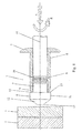
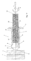
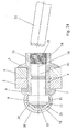
- FIG. 1 is a first embodiment of a blind rivet 3 according to the invention
- the one a set head 5 having blind rivet sleeve 4 and a coaxially guided in the bore 6 rivet mandrel 7, at the blind end 9 of the blind rivet 4 a mandrel head 8 with a cylindrical, to the longitudinal axis 10 of the mandrel 7 symmetrical portion 11 has, the Diameter larger than that of Blindniethülse 4 and is in a feed direction frustoconical portion 12 of the mandrel head 8 with the longitudinal axis 11 of the mandrel 7th perpendicular end face 13 passes.
- the blind end 9 of the blind rivet 4 is located with its annular end surface 14 at the end face 13 of the frustoconical Section 12 of the mandrel head 8 opposite end face 15 of the cylindrical portion 11 of the mandrel head 8 at.
- the rivet mandrel 7 is located at its in the blind rivet 4 Length section provided with a predetermined breaking point 16, preferably at the end of in Feed direction of the front third of his located in the blind rivet 4 length section.
- the entire blind rivet 3 is rotated with a rotational movement R and an axially directed feed force A against the mandrel head 8 facing first Part 1 pressure moderately led.
- This takes place in the processing area 17 of the first component. 1 by the axial force acting on the rotational movement R and in the feed direction Dornkopfes 8 caused friction and forming a heat input into the Component material, by which this is made flowable, as Fig. 2 illustrates.
- the rotating mandrel head 8 continues to form in this way continuously Components 1 and 2 passing through flow hole 18, the non-cutting of the blind rivet 3 continuously is penetrated until the setting head 5 of Blindniethggse 4 on the first component 1 for Plant comes.
- Fig. 3 illustrates, with the surface of the mandrel head 8 and the Outer jacket 19 of Blindniethülse 4 at the blind end 9 by Reibungsversch conductedung cap-like manner, in such a way that according to the the components 1 and 2 successively in F diffuselochformen displaced superfluous Component materials form two overlapping caps 20 and 21, of which the outer Cap 20, the rear annular end face 15 of the mandrel head 8 against the end of the 9 Blind rivet sleeve 4 sealingly overlaps.
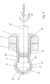
- FIGS. 6 to 10 shows a further procedure, which with the in connection With reference to FIGS. 1 to 5 described method for connecting components with one-sided Accessibility except for the difference that, as Fig. 6 shows that the mandrel head 8 of the rivet mandrel 7 of the blind rivet 3 facing first component 1 is provided with a pre-perforation 24 whose diameter is slightly larger than the diameter of the cylindrical Section 11 of the mandrel head 8 is.
- a pre-perforation 24 whose diameter is slightly larger than the diameter of the cylindrical Section 11 of the mandrel head 8 is.
- FIG. 6 and 7 shows the longitudinal axis 10 of the blind rivet 3 with respect to the center line 25 of the pre-perforation 24 of the first component 1 aligned in alignment and the mandrel head 8 of the rotated Blind rivet 3 then purposefully guided through the pre-perforation 24 of the first component 1 and through the axially directed feed force A against the component 1 facing surface 26 of the second Part 2 pressed.
- This is done in the processing area 27 of the second component 2 by the Friction and forming work, due to the rotational movement of the mandrel head 8 and the in Feed direction acting axial force of the mandrel head 8 is formed, a heat input in the second component 2, through which the component material is made flowable.
- the further process the sealingly firm connection of the two components 1 and 2 then corresponds to that in relation to Figs. 3 to 5 described procedure.
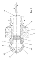
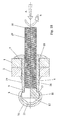
- FIGS. 11 to 15 another embodiment of the blind rivet 3 for connecting the Components 1 and 2 with one-sided accessibility according to the procedure of FIGS. 1 to 5, wherein the blind rivet 3 instead of the mandrel 7 according to FIGS. 1 to 10 a Blind rivet threaded bolt 28 which is guided in the Blindniethülse 4 and a mandrel head 8, which, as shown in the upper half of the sectional view of FIG. 11, identical as the mandrel head 8 of the mandrel 7 according to FIGS. 1 to 10 is formed.
- the blind rivet 4 and the blind rivet threaded bolt 28 are materially connected to the mandrel head 8, so that e.g. an absolute Tightness is possible.
- FIGS. 11 to 15 for connecting the two components 1 and 2 with one-sided accessibility corresponds to the principle of F thoroughlylochblindnietens of FIG. 1st to 5 with the difference that after sealingly firmly joining the two Components 1 and 2 through the Blindniet 3 of Blindnietgewindebolzen 28 continue from the open rear end 23 of Blindniethülse 4 extends and available for mounting purposes is.
- FIGS. 16 to 20 is a fourth embodiment of the method for connecting the both components 1 and 2 with one-sided accessibility, according to the procedure 6 to 10 to the effect that the blind rivet 3 facing component 1 with the corresponding Vorlochung 24 is provided and the rotated blind rivet 3 with the Mandrel 8 is guided purposefully through this Vorlochung 24.
- blind rivet 3 according to FIGS. 6 to 10 is shown in FIGS. 16 to 20 of the blind rivet 3 in accordance with FIG Embodiment according to FIGS. 11 to 15 provided with the Blindnietgewindebolzen 28.
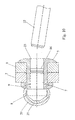
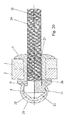
- Fig. 21 is a modified embodiment of the blind rivet 3 of FIG. 1 for connecting the two components 1 and 2 with one-sided accessibility, in which the jacket 30 of the frustoconical portion 12 of the mandrel head 8 with circumferential, the end face 13 of the Mandrel head 8 parallel grooves 31 is provided. Furthermore, the frusto-conical portion 12 of the mandrel head 8 at its transition to the cylindrical Section 11 of the mandrel head 8 be designed so that a relative to the cylindrical Section 12 radially projecting shoulder 32 is formed, as can be seen in Fig. 21. In the lower half of the sectional view of FIG. 21 is further shown that the blind rivet 4 and the rivet mandrel 7 in this embodiment of the blind rivet 3 materially together may be connected, e.g. absolute sealing is possible.
- FIG. 22 shows another embodiment of the blind rivet 3 in the blind rivet sleeve 4 guided Blindnietgewindebolzen 28 during compression of the blind end 9 of the Blind rivet 4 for riveting the two components 1 and 2, wherein according to FIG. 21 in Sheath 30 of the frustoconical portion 12 of the mandrel head 8 circumferential, the end face 13 of the mandrel head 8 parallel grooves 31 are provided and at the transition of the frustoconical D ornkopfab section 12 to the cylindrical mandrel head portion 11 a radial protruding paragraph 32 is formed.
- FIG. 22 shows another embodiment of the blind rivet 3 in the blind rivet sleeve 4 guided Blindnietgewindebolzen 28 during compression of the blind end 9 of the Blind rivet 4 for riveting the two components 1 and 2, wherein according to FIG. 21 in Sheath 30 of the frustoconical portion 12 of the mandrel head 8 circumferential, the end face 13 of the mandrel head 8 parallel groove
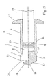
- Fig. 23 is another embodiment of the blind rivet 3 with setting head side of Blindniethülse 4 in one piece with this trained blind rivet nut 33 as a functional element.
- the rivet mandrel 7 guided in the blind rivet sleeve 4 is also provided with a rivet mandrel 7 in the latter lying predetermined breaking point 16 and the frusto-conical portion 12 of the Mandrel 8 of Nietdorns 7 formed with circumferential grooves 31, wherein at least one Edge of each groove 31 is parallel to the end face 13 of the mandrel head 8 and at the transition of the frustoconical mandrel head portion 12 to the cylindrical mandrel head portion 11 a radially paragraph 32 above.
- FIG. 23 In the lower half of the sectional view of FIG. 23 is also shown the alternative of the material connection of blind rivet 4 and rivet mandrel 7.
- the Blindniet 3 in the embodiment as blind rivet nut 35th According to Fig. 23 in the two components 1 and 2 sealingly interconnecting position shows, after compression of the blind-side end 9 of the blind rivet sleeve 4 up to the breakage of Rivet mandrel 7 at its lying in the blind rivet sleeve 16 breaking point 16 and after removal of Restnietdorns 22 from the blind rivet 4, the internal thread 34 of the setting head side Bore 35 of blind rivet nut 33 for mounting purposes e.g. by means of a not shown Threaded bolt available.
- blind rivet 3 shown in FIG. 25 which in particular has proven to be favorable in blind riveting of unilaterally accessible aluminum components, is on the end face 13 of the frustoconical mandrel head portion 12 coaxially in Feed direction extending frusto-conical centering element 36 with relatively provided small base diameter.
Landscapes
- Engineering & Computer Science (AREA)
- Mechanical Engineering (AREA)
- General Engineering & Computer Science (AREA)
- Insertion Pins And Rivets (AREA)
- Lining Or Joining Of Plastics Or The Like (AREA)
Abstract
Description
Die Erfindung betrifft ein Verfahren zum Verbinden von Bauteilen mit einseitiger Zugänglichkeit unter Verwendung eines Blindniets mit einer einen Setzkopf aufweisenden Blindniethülse und einem in deren Bohrung koaxial geführten Nietdorn, der am blindseitigen Ende des Blindniets einen Dornkopf aufweist, dessen Durchmesser größer als der der Blindniethülse ist.The invention relates to a method for joining components with one-sided accessibility using a blind rivet with a set head having blind rivet sleeve and a coaxially guided in its bore rivet mandrel, which at the blind end of the blind rivet a mandrel head whose diameter is greater than that of the Blindniethülse.
Die Erfindung betrifft ferner eine Vorrichtung zum Verbinden von Bauteilen mit einseitiger Zugänglichkeit, bestehend aus einem Blindniet mit einer einen Setzkopf aufweisenden Blindniethülse und einem in deren Bohrung koaxial geführten Nietdorn, der am blindseitigen Ende des Blindniets einen Dornkopf aufweist, dessen Durchmesser größer als der der Blindniethülse ist, sowie aus einer Antriebseinrichtung zum Setzen des Blindniets.The invention further relates to a device for connecting components with one-sided Accessibility, consisting of a blind rivet with a set head having Blind rivet and a coaxially guided in its bore rivet mandrel, which at the blind side End of the blind rivet has a mandrel head whose diameter is greater than that of Blind rivet is, as well as a drive device for setting the blind rivet.
Bei einem bekannten Verfahren zum Fügen von aufeinanderliegenden dünnen Blechen (DE 197 01 252 Al) wird mit einem aufgesetzten Bolzenschußgerät ein eine Niethülse aufweisender Hohlniet und ein in der Niethülse koaxial steckender Nietdorn die Bleche durchsetzend eingetrieben, bis ein einschußseitiger Setzkopf des Hohlniets an dem einschußseitigen Blech anschlägt, wobei das austrittsseitige Hohlnietende von innen zu einem das andere Blech übergreifenden Schließkopf aufgeweitet wird. Der Nietdorn ist mit einem frontseitig erweiterten Kopf versehen, der die Niethülse frontseitig abdeckt und vorn einen Spitzkonus und hinten einen Spreizkonus trägt. Nach dem Einschießen wird der Nietdorn ganz zurückgezogen oder teilweise zurückgezogen und abgebrochen.In a known method for joining superposed thin sheets (DE 197 01 252 Al) with an attached nail gun a rivet having Hollow rivet and a rivet pin coaxially inserted in the rivet sleeve penetrating the sheets driven until a Einschußseitiger setting head of the rivet on the Einschußseitigen sheet strikes, wherein the exit-side Hohlnietende from the inside to a the other sheet overarching closing head is widened. The rivet mandrel is extended with a front Head provided, which covers the rivet sleeve front and front a pointed cone and the rear one Spreading cone carries. After shooting, the rivet pin is completely retracted or partially withdrawn and canceled.
Bekannt ist weiterhin (DE 197 16 431 Al), mit Hilfe des Fließlochformens in dünnwandigen Bauteilen, Blechen, Profilen oder Hohlprofilen Durchzüge zu erzeugen. Hierbei wird ein schnellrotierender Hartmetallkegeldorn mit polygonalem Formgebungsquerschnitt unter axialer Kraftbeaufschlagung auf das Werkstück gedrückt. Die entstehende Reibungs- und Umformarbeit bewirkt eine deutliche Temperaturerhöhung im Bereich der Bearbeitungsstelle und setzen hierdurch die Festigkeit des Werkstoffes herab. Der Fließformdorn läßt sich unter reduziertem Kraftaufwand durch das Blech drücken. Etwa 40% des beim Fließformen verdrängten Materials werden entgegen der Vorschubrichtung des Fließformdorns nach oben verdrängt.It is also known (DE 197 16 431 A1), with the help of flow hole forming in thin-walled Components, sheets, profiles or hollow profiles to produce passages. This is a fast rotating carbide cone with polygonal forming cross section under axial Force applied to the workpiece. The resulting friction and forming work causes a significant increase in temperature in the area of the processing point and set This reduces the strength of the material. The Fließformdorn can be under reduced Forcing effort through the sheet. About 40% of the material displaced during flow forming are displaced upwards against the feed direction of the flow forming mandrel.
Zum Verbinden von beidseitig zugänglichen Bauteilen dient ferner ein selbstbohrender Blindniet, wie er aus der DE 40 01 723 C2 hervorgeht. Dieser bekannte selbstbohrende Blindniet umfaßt einen Nietkörper, der eine Bohrung hat, einen Dorn, der in der Bohrung des Nietkörpers eingefangen ist und einen Flansch an seinem einen Ende hat, welcher den gleichen Durchmesser wie der Nietkörper besitzt, und einen Bohrer, der einen geschmiedeten Bohrabschnitt aufweist und an dem Flansch vorgesehen ist. Beim Einsatz des selbstbohrenden Blindniets erweisen sich die vom Bohrer erzeugten Werkstoffbohrspäne jedoch als nachteilig, die in nicht kontrollierbarer Weise in die Nietverbindung geraten können, so daß deren Festigkeit unter Umständen nicht gewährleistet ist.For connecting components accessible from both sides, a self-drilling blind rivet is also used, as can be seen from DE 40 01 723 C2. This known self-drilling blind rivet includes a rivet body having a bore, a spike located in the bore of the rivet body is captured and has a flange at its one end, which has the same diameter as the rivet body possesses, and a drill, which has a forged drill section and is provided on the flange. When using the self-drilling blind rivet turn out to be However, the material chips generated by the drill as disadvantageous in uncontrollable Way may get into the riveted, so that their strength may not is guaranteed.
Bekannt ist schließlich ein Blindniet mit einem hülsenförmigen Nietkörper und einem in diesen liegenden Nietschaft, der einen erweiterten Nietkopf am blindseitigen Ende trägt (deutsches Gebrauchsmuster G 93 02 633.1 U1). Ein solcher Blindniet wird bei einseitiger Zugänglichkeit eines Bauteiles, z.B. einer Wandplatte verwendet. Der Blindniet wird in eine Bohrung der Wandplatte eingefügt, und anschließend wird der Nietschaft zusammen mit dem Nietkopf zurückgezogen, so daß der Nietkopf den hülsenförmigen Nietkörper von der Blindseite her auseinandertreibt und damit auf der Blindseite verankert. Um ein Vorbohren der Wandplatte unnötig zu machen, kann der Nietschaft mit einer scharfen Spitze versehen werden, so daß der Blindniet mit Hilfe eines Setzgerätes durch ein dünnwandiges, verhältsnismäßig weiches Plattenmaterial, wie Sperrholz, Gipskarton, Pappe und dergleichen hindurchgestoßen und anschließend verankert werden kann. Finally, a blind rivet with a sleeve-shaped rivet body and one in it is known lying rivet shaft, which carries an extended rivet head at the blind end (German Utility model G 93 02 633.1 U1). Such a blind rivet is one-sided accessibility a component, e.g. used a wall plate. The blind rivet gets into a hole in the Inserted wall plate, and then the rivet shank together with the rivet head withdrawn, so that the rivet head the sleeve-shaped rivet body from the blind side ago disperse and anchored on the blind side. To pre-drill the wall plate To make unnecessary, the rivet can be provided with a sharp point, so that the Blind rivet with the help of a setting tool through a thin-walled, relatively soft Sheet material such as plywood, plasterboard, cardboard and the like pushed through and can then be anchored.
Insbesondere im Kraftfahrzeugbau sind geeignete Fügeverfahren bei einseitiger Zugänglichkeit der Fügestelle, z.B. für die Anbindung von Blechen an einseitig zugängliche Profile gefordert.Especially in motor vehicle construction are suitable joining methods with one-sided accessibility the joint, e.g. required for the connection of sheets to unilaterally accessible profiles.
Der Erfindung liegt daher die Aufgabe zugrunde, ein Verfahren zum Verbinden von Bauteilen mit einseitiger Zugänglichkeit gemäß der eingangs erwähnten Art sowie eine Vorrichtung zu dessen Durchführung zur Verfügung zu stellen, mit dem bzw. der ohne Anfall von Werkstoffbohrspänen und ohne unzulässige Verformungen von Bauteilflächen eine vollständig dichte Verbindungsstelle der zu verbindenden Bauteile erzielt werden kann.The invention is therefore based on the object, a method for connecting components with one-sided accessibility according to the type mentioned above and a device to its implementation, with or without seizure of Material drill chips and without undue deformation of component surfaces a complete tight connection point of the components to be joined can be achieved.
Diese Aufgabe wird erfindungsgemäß erreicht durch die Kombination der folgenden Verfahrensschritte:
- der Dornkopf des Nietdorns des Blindniets wird derart ausgebildet, daß ein am blindseitigen Ende der Blindniethülse angeordneter zylindrischer, zur Längsachse des Nietdorns symmetrischer Dornkopfabschnitt, dessen Durchmesser größer als der der Blindniethülse ist, in einen in Vorschubrichtung des Blindniets kegelstumpfförmigen Dornkopfabschnitt mit zur Längsachse des Nietdorns senkrecht verlaufender Stirnfläche übergeht,
- der gesamte Blindniet wird um seine Längsachse in Drehung versetzt und mit der planen Stirnfläche des rotierenden Dornkopfes mit einer axial gerichteten Vorschubkraft gegen das dem Dornkopf zugewandte Bauteil gedrückt,
- wobei der Bauteilwerkstoff im Bereich der Bearbeitungsstelle erwärmt und fließfähig gemacht wird, der rotierende Dornkopf fortlaufend ein die beiden Bauteile durchsetzendes Fließloch unter Verdrängung des überschüssigen Bauteilwerkstoff aus dem Fließloch formt, der mit dem Dornkopf kappenartig verbunden wird, und der Blindniet spanlos die Bauteile durchdringt, bis der Setzkopf der Bindniethülse an dem dieser zugewandten Bauteil zur Anlage kommt,
- worauf der Nietdorn durch eine zur axial gerichteten Vorschubkraft entgegengesetzt gerichteten Axialkraft zurückgezogen wird und die Blindniethülse blindseitig dabei derart gestaucht wird, daß die Bauteile durch den Blindniet abdichtend fest miteinander verbunden werden und der Dornkopf in der Verbindungsstelle der beiden Bauteile verbleibt.
- the mandrel head of the rivet mandrel of the blind rivet is formed such that a cylindrical, at the blind end of the blind rivet sleeve arranged cylindrical, symmetrical to the longitudinal axis of the rivet mandrel mandrel head portion, whose diameter is greater than that of the blind rivet, in a feed direction of the blind rivet frustoconical mandrel head portion with the longitudinal axis of the rivet mandrel perpendicular passing over the end face,
- the entire blind rivet is rotated about its longitudinal axis and pressed with the flat face of the rotating mandrel head with an axially directed feed force against the mandrel head facing component,
- wherein the component material is heated and made to flow in the region of the processing point, the rotating mandrel head continuously forms a flow passage passing through the two components, displacing the surplus component material from the flow hole, which is connected in a cap-like manner with the mandrel head, and the blind rivet passes through the components without cutting, until the setting head of the binding rivet sleeve on which this facing component comes to rest,
- whereupon the rivet mandrel is retracted by an axial force directed oppositely to the axially directed feed force and the blind rivet sleeve is compressed on the blind side in such a way that the components are sealingly firmly connected to one another by the blind rivet and the mandrel head remains in the connection point of the two components.
Vorzugsweise wird bei der Fließlochformung des rotierenden Dornkopfes der von diesem aus dem Fließloch verdrängte überflüssige Bauteilwerkstoff mit dem Dornkopf kaltverschweißt und/oder mechanisch formschlüssig verbunden. Bevorzugt wird auch ein Nietdorn verwendet, der eine innerhalb der Blindniethülse gelegene Sollbruchstelle aufweist, wobei die Stauchung des blindseitigen Endes der Niethülse durch die Einwirkung der den Setzkopf der Blindniethülse beaufschlagenden axial gerichteten Vorschubkraft und der zu letzterer entgegengesetzten, am Nietdorn angreifenden Axialkraft bis hin zum Bruch der Sollbruchstelle des Nietdorns erfolgt, worauf der Restnietdorn aus dem offenen Ende der Blindniethülse entfernt wird, während der Dornkopf in der abgedichteten festen Verbindungsstelle der beiden Bauteile verbleibt. Es kann auch ein Blindniet verwendet werden, bei dem in der Bohrung der Blindniethülse anstelle des Nietdorns ein Blindnietgewindebolzen geführt ist, dessen Dornkopf nach dem Blindnieten der beiden Bauteile in deren Verbindungsstelle verbleibt und der sich weiterhin aus dem offenen Ende der Blindniethülse erstreckt und für Montagezwecke verfügbar ist. Alternativ kann auch ein Blindniet verwendet werden, dessen Blindniethülse an ihrem setzkopfseitigen Ende mit einer Blindnietmutter als Funktionselement ausgebildet wird. Der Mantel des kegelstumpfförmigen Abschnitts des Dornkopfes des Nietdorns bzw. des Blindnietgewindebolzens kann mit umlaufenden Nuten versehen werden, in denen der vom Dornkopf beim Fließformen verdrängte überflüssige Bauteilwerkstoff formschlüssig mit dem Dornkopf verbunden wird. Die umlaufenden Nuten können so im Dornkopf ausgebildet werden, daß mindestens eine Oberkante der Nuten parallel zur Stirnfläche des kegelstumpfförmigen Abschnitts des Dornkopfes verläuft, wodurch eine optimale mechanische formschlüssige Verbindung des den Dornkopf kappenartig umfassenden überschüssigen Bauteilwerkstoffes mit dem Dornkopf gewährleistet wird. Von Wichtigkeit ist ferner, daß die Geometrie des Dornkopfes sowie die auf den Blindniet ausgeübte axialgerichtete Vorschubkraft und die Rotationsgeschwindigkeit des Dornkopfes so aufeinander abgestimmt werden, daß der vom Dornkopf beim Fließformen verdrängte überflüssige Bauteilwerkstoff und der Dornkopf eine mechanische formschlüssige Verbindung eingehen. Auch kann die Blindniethülse an ihrem blindseitigen Ende mit dem Nietdorn bzw. dem Blindnietgewindebolzen des Blindniets stofflich verbunden gestaltet werden, und es ist möglich, mehr als zwei Bauteile gleichzeitig mit dem erfindungsgemäßen Verfahren mit einem Blindniet problemlos zu verbinden. Zur zielgenaueren Führung des rotierenden Dornkopfes gegen die zugewandte Bauteilfläche im entsprechenden Bearbeitungsbereich eignet sich eine Ausführungsform des Blindniet , bei der auf der Stirnfläche des kegelstumpfförmigen Abschnitts des Dornkopfes koaxial ein verhältnismäßig kleines, kegelstumpfförmiges Zentrierelement als Aufsatzspitze ausgebildet ist. Der Einsatz dieser Ausführungsform hat sich insbesondere beim Blindvernieten einseitig zugänglicher Bauteile aus Aluminium als vorteilhaft erwiesen.Preferably, in the flow-hole forming of the rotating mandrel head of the latter from this superfluous component material displaced from the flow hole is cold-welded to the mandrel head and / or mechanically positively connected. Preferably, a rivet mandrel is also used, having a predetermined breaking point located within the Blindniethülse, wherein the compression of the Blind side end of the rivet by the action of the setting head of Blindniethülse acting axially directed feed force and the latter opposite, on Nietdorn attacking axial force up to the breaking of the predetermined breaking point of the rivet mandrel takes place, whereupon the residual rivet mandrel is removed from the open end of the blind rivet sleeve during the Mandrel head remains in the sealed fixed joint of the two components. It can a blind rivet be used in which in the bore of the blind rivet sleeve instead of Nietdorns a Blindnietgewindebolzen is performed, the mandrel head after blind riveting the two components remains in the junction and further from the open End of the blind rivet sleeve extends and is available for mounting purposes. Alternatively, too a Blindniet be used, the Blindniethülse at its head end with a Blind rivet nut is designed as a functional element. The mantle of the frustoconical Section of the mandrel head of the rivet mandrel or Blindnietgewindebolzens can with circumferential grooves are provided in which displaced by the mandrel head during flow forming superfluous component material is positively connected to the mandrel head. The circumferential grooves can be formed in the mandrel head so that at least one upper edge the grooves are parallel to the end face of the frusto-conical portion of the mandrel head, whereby an optimal mechanical positive connection of the mandrel head cap-like comprehensive surplus component material is ensured with the mandrel head. From It is also important that the geometry of the mandrel head and the force exerted on the blind rivet axially directed feed force and the rotational speed of the mandrel head to each other be tuned that displaced by the mandrel head during flow forming superfluous component material and the mandrel head enter into a mechanical positive connection. Also can the blind rivet at its blind end with the rivet mandrel or the Blind rivet threaded bolts of the blind rivet are made materially connected, and it is possible more than two components simultaneously with the method according to the invention with a blind rivet easy to connect. For more precise guidance of the rotating mandrel head against the facing component surface in the corresponding processing area is suitable Embodiment of the blind rivet, in which on the end face of the frusto-conical portion the mandrel head coaxially a relatively small, frustoconical centering as Attachment tip is formed. The use of this embodiment has been particularly in the Blind riveting unilaterally accessible aluminum components proved to be advantageous.
Die erfindungsgemäße Vorrichtung zur Durchführung des oben beschriebenen Verfahrens zeichnet sich dadurch aus, daß die Blindniethülse und der Nietdorn gemeinsam von der Antriebseinrichtung um die Längsachse des Blindniets in Drehung versetzbar und zugleich in Vorschubrichtung des Blindniets axial vortreibbar sind, der Dornkopf des Nietdorns am blindseitigen Ende des Blindniethülse einen zylindrischen, zur Längsachse des Nietdorns symmetrisch angeordneten Dornkopfabschnitt aufweist, dessen Durchmesser größer als der der Blindniethülse ist und der in einen in Vorschubrichtung des Dornkopfes kegelstumpfförmigen Dornkopfabschnitt übergeht, dessen zur Längsachse des Nietdorns senkrecht verlaufende Stirnfläche gegen die gegenüberliegende Fläche des benachbarten Bauteils beim axial gerichteten Vortrieb des Blindniets rotierend drückbar ist, wobei der Bauteilwerkstoff im Bearbeitungsbereich des ersten Bauteils erwärmbar und in fließfähigen Zustand versetzbar und ein die Bauteile durchsetzendes Fließloch formbar ist, durch das der Blindniet bis zum Anschlag des Setzkopfes an der Fläche des ersten Bauteils rotierend vortreibbar ist, und daß dann der Nietdorn von der Antriebseinrichtung mittels einer Axialkraft, die zur axial gerichteten Vorschubkraft entgegengesetzt gerichtet ist, relativ zur Blindniethülse bei Stauchung des blindseitigen Endes der Blindniethülse bis zur Festsetzung des Dornkopfes in der abgedichteten Verbindungsstelle der beiden Bauteile axial rückziehbar ist.The device according to the invention for carrying out the method described above is characterized by the fact that the blind rivet and the rivet mandrel jointly from the Drive device about the longitudinal axis of the blind rivet in rotation and at the same time in Feed direction of the blind rivet are axially propelled, the mandrel head of the rivet mandrel on blind-side end of Blindniethülse a cylindrical, to the longitudinal axis of the rivet mandrel having symmetrically arranged mandrel head portion whose diameter is larger than that of Blind rivet is and the frustoconical in a feed direction of the mandrel head Mandrel head section merges, the perpendicular to the longitudinal axis of the mandrel End face against the opposite surface of the adjacent component in the axially directed Propulsion of the blind rivet is rotatably pressed, wherein the component material in the Processing area of the first component heated and displaceable in the flowable state and a flow hole penetrating the components is malleable, through which the blind rivet up to the stop of the setting head on the surface of the first component is rotatably propelled, and that then the Riveting mandrel from the drive means by means of an axial force which is directed to the axially Feed force is directed opposite, relative to Blindniethülse in compression of the blind end of the Blindniethülse until the fixing of the mandrel head in the sealed Joint of the two components is axially retractable.
Vorteilhafte Weiterbildungen der erfindungsgemäßen Vorrichtung gehen aus den
Patentansprüchen 13 bis 17 hervor.Advantageous developments of the device according to the invention go from the
Das erfindungsgemäße Verfahren ermöglicht in überraschender Weise ein praktisch gratloses und zugleich spanloses Blindvernieten von Bauteile mit einseitiger Zugänglichkeit. Unzulässige Verformungen der Bauteilflächen wie beim Nietschießen treten nicht auf, und die Wärmeeinflußzonen sind in den zu verbindenden Bauteilen beim Fließlochformen verhältnismäßig klein. Außerdem wird mit dem erfindungsgemäßen Verfahren eine vollständige Dichtigkeit der Bauteilverbindung erzielt.The process of the invention surprisingly allows a virtually flawless and at the same time non-cutting blind riveting of components with one-sided accessibility. Unacceptable Deformations of the component surfaces as in rivet shooting do not occur, and the Heat affected zones are in the components to be joined during flow hole forming relatively small. In addition, with the inventive method a complete Tightness of the component connection achieved.
Die Erfindung wird nun anhand der Zeichnungen erläutert. In diesen sind:
Aus Fig. 1 geht eine erste Ausführungsform eines Blindniets 3 zum erfindungsgemäßen
Verbinden von Bauteilen 1 und 2 mit einseitiger Zugänglichkeit hervor, der eine einen Setzkopf
5 aufweisende Blindniethülse 4 und einen in deren Bohrung 6 koaxial geführten Nietdorn 7 aufweist,
der am blindseitigen Ende 9 der Blindniethülse 4 einen Dornkopf 8 mit einem
zylindrischen, zur Längsachse 10 des Nietdorns 7 symmetrischen Abschnitt 11 besitzt, dessen
Durchmesser größer als der der Blindniethülse 4 ist und der in einen in Vorschubrichtung
kegelstumpfförmigen Abschnitt 12 des Dornkopfes 8 mit zur Längsachse 11 des Nietdorns 7
senkrecht stehender Stirnfläche 13 übergeht. Das blindseitige Ende 9 der Blindniethülse 4 liegt
mit seiner ringförmigen Stirnfläche 14 an der zur Stirnfläche 13 des kegelstumpfförmigen
Abschnitts 12 des Dornkopfes 8 entgegengesetzten Stirnfläche 15 des zylindrischen Abschnitts
11 des Dornkopfes 8 an. Der Nietdorn 7 ist an seinem in der Blindniethülse 4 gelegenen
Längenabschnitt mit einer Sollbruchstelle 16 versehen, und zwar vorzugsweise am Ende des in
Vorschubrichtung vorderen Drittels seines in der Blindniethülse 4 gelegenen Längenabschnitts.From Fig. 1 is a first embodiment of a
Bei einer ersten Verfahrensweise wird der gesamte Blindniet 3 mit einer Rotationsbewegung R
und einer axial gerichteten Vorschubkraft A gegen das dem Dornkopf 8 zugewandte erste
Bauteil 1 druckmäßig geführt. Hierbei erfolgt im Bearbeitungsbereich 17 des ersten Bauteils 1
durch die von der Rotationsbewegung R und der in Vorschubrichtung wirkenden Axialkraft des
Dornkopfes 8 hervorgerufene Reibungs- und Umformarbeit ein Wärmeeintrag in den
Bauteilwerkstoff, durch den dieser fließfähig gemacht wird, wie Fig. 2 verdeutlicht. Wie aus Fig.
3 hervorgeht, formt der rotierende Dornkopf 8 auf diese Weise weiterhin fortlaufend ein die
Bauteile 1 und 2 durchsetzendes Fließloch 18, das von dem Blindniet 3 kontinuierlich spanlos
durchdrungen wird, bis der Setzkopf 5 der Blindniethülse 4 an dem ersten Bauteil 1 zur
Anlage kommt. Der beim Fließlochformen des Dornkopfes 8 von diesem verdrängte überflüssige
Bauteilwerkstoff wird, wie Fig. 3 verdeutlicht, mit der Oberfläche des Dornkopfes 8 sowie dem
Außenmantel 19 der Blindniethülse 4 an deren blindseitigen Ende 9 durch
Reibungverschweißung kappenartig verbunden, und zwar derart, daß sich entsprechend den aus
den Bauteilen 1 und 2 nacheinander beim Fließlochformen verdrängten überflüssigen
Bauteilwerkstoffen zwei überlappenden Kappen 20 und 21 bilden, von denen die außen liegende
Kappe 20 die rückwärtige ringförmige Stirnfläche 15 des Dornkopfes 8 gegen das Ende 9 der
Blindniethülse 4 abdichtend übergreift.In a first procedure, the entire
Das abdichtende feste Verbinden der beiden einseitig zugänglichen Bauteile 1 und 2 miteinander
erfolgt, indem der Nietdorn 4 aus der in Fig. 3 gezeigten Position durch eine Axialkraft B, die
entgegengesetzt zu der den Setzkopf 5 der Blindniethülse 4 beaufschlagenden axialen
Vorschubkraft A gerichtet wird, derart zurückgezogen wird, daß eine Verformung des
blindseitigen Endes 9 der Blindniethülse 4 bis hin zum Bruch des Nietdorns 7 an seiner
Sollbruchstelle 16 erfolgt. Der abgebrochene Restnietdorn 22 wird dann aus dem offenen Ende
23 der Blindniethülse 4 entfernt, während der Dornkopf 8 in der Verbindungsstelle der beiden
Bauteile 1 und 2 verbleibt.The sealing fixed connection of the two unilaterally
Aus den Fig. 6 bis 10 geht eine weitere Verfahrensweise hervor, die mit dem im Zusammenhang
mit den Fig. 1 bis 5 beschriebene Verfahren zum Verbinden von Bauteilen mit einseitiger
Zugänglichkeit bis auf den Unterschied übereinstimmt, daß, wie Fig. 6 zeigt, das dem Dornkopf
8 des Nietdorns 7 des Blindniets 3 zugewandte erste Bauteil 1 mit einer Vorlochung 24 versehen
worden ist, deren Durchmesser geringfügig größer als der Durchmesser des zylindrischen
Abschnitts 11 des Dornkopfes 8 ist. Bei dieser Verfahrensweise wird, wie aus den Fig. 6 und 7
hervorgeht, die Längsachse 10 des Blindniets 3 in Bezug auf die Mittellinie 25 der Vorlochung
24 des ersten Bauteils 1 fluchtend ausgerichtet und der Dornkopf 8 des in Drehung versetzten
Blindniets 3 dann zielgerichtet durch die Vorlochung 24 des ersten Bauteils 1 geführt und durch
die axialgerichtete Vorschubkraft A gegen die dem Bauteil 1 zugewandte Fläche 26 des zweiten
Bauteils 2 gedrückt. Hierbei erfolgt im Bearbeitungsbereich 27 des zweiten Bauteils 2 durch die
Reibungs- und Umformarbeit, die infolge der Rotationsbewegung des Dornkopfes 8 und die in
Vorschubrichtung wirkende Axialkraft des Dornkopfes 8 entsteht, ein Wärmeeintrag in den
zweiten Bauteils 2 , durch den der Bauteilwerkstoff fließfähig gemacht wird. Der weitere Ablauf
des abdichtend festen Verbindens der beiden Bauteile 1 und 2 entspricht dann der in Bezug auf
die Fig. 3 bis 5 beschriebenen Verfahrensweise. From Figs. 6 to 10 shows a further procedure, which with the in connection
With reference to FIGS. 1 to 5 described method for connecting components with one-sided
Accessibility except for the difference that, as Fig. 6 shows that the
Aus den Fig. 11 bis 15 geht eine andere Ausführungsform des Blindniets 3 zum Verbinden der
Bauteile 1 und 2 mit einseitiger Zugänglichkeit gemäß der Verfahrensweise nach den Fig. 1 bis
5 hervor, wobei der Blindniet 3 anstelle des Nietdorns 7 nach den Fig. 1 bis 10 einen
Blindnietgewindebolzen 28 aufweist, der in der Blindniethülse 4 geführt ist und einen Dornkopf
8 aufweist, der, wie aus der oberen Hälfte der Schnittansicht nach Fig. 11 hervorgeht, identisch
wie der Dornkopf 8 des Nietdorns 7 nach den Fig. 1 bis 10 ausgebildet ist. In der unteren
Hälfte der Schnittansicht nach Fig. 11 ist eine Variante der Ausführungsform des Blindniets 3
nach den Fig. 11 bis 15 dargestellt, bei der die Blindniethülse 4 und der Blindnietgewindebolzen
28 an dessen Dornkopf 8 stofflich miteinander verbunden sind, damit z.B. eine absolute
Dichtigkeit möglich ist.From FIGS. 11 to 15, another embodiment of the
Die den Fig. 11 bis 15 entnehmbare Verfahrensweise zum Verbinden der beiden Bauteile 1 und 2
mit einseitiger Zugänglichkeit entspricht dem Prinzip des Fließlochblindnietens nach den Fig. 1
bis 5 mit dem Unterschied, daß sich nach dem abgedichtend festen Verbinden der beiden
Bauteile 1 und 2 durch den Blindniet 3 der Blindnietgewindebolzen 28 weiterhin aus dem
offenen rückwärtigen Ende 23 der Blindniethülse 4 erstreckt und für Montagezwecke verfügbar
ist.The method shown in FIGS. 11 to 15 for connecting the two
Aus den Fig. 16 bis 20 ist eine vierte Ausführungsform des Verfahrens zum Verbinden der
beiden Bauteile 1 und 2 mit einseitiger Zugänglichkeit ersichtlich, die der Verfahrensweise nach
den Fig. 6 bis 10 dahingehend enstpricht, daß das dem Blindniet 3 zugewandte Bauteil 1 mit der
entsprechenden Vorlochung 24 versehen wird und der in Drehung versetzte Blindniet 3 mit dem
Dornkopf 8 zielgerichtet durch dieses Vorlochung 24 geführt wird. Im Unterschied zu dem
Blindniet 3 nach den Fig. 6 bis 10 ist nach den Fig. 16 bis 20 der Blindniet 3 entsprechend der
Ausführungsform nach den Fig. 11 bis 15 mit dem Blindnietgewindebolzen 28 versehen. Die
Verfahrensweise des Blindnietens mittels des Blindnietgewindebolzens 28 erfolgt entsprechend
dem zuvor beschriebenen Ablauf des Fließlochblindnietens mit vorgelochtem Bauteil 1, wobei
nach abgedichtend festen Verbinden der beiden Bauteile 1 und 2 der Blindnietgewindbolzen 28
mit seiner gesamten Länge erhalten bleibt und mit seinem sich aus dem offenen rückwärtigen
Ende 23 der Blindniethülse 4 erstreckenden Längenabschnitt 29 für Montagezwecke verfügbar
ist.From Figs. 16 to 20 is a fourth embodiment of the method for connecting the
both
Aus Fig. 21 geht eine abgeänderte Ausführungsform des Blindniets 3 nach Fig. 1 zum Verbinden
der beiden Bauteile 1 und 2 mit einseitiger Zugänglichkeit hervor, bei der der Mantel 30 des
kegelstumpfförmigen Abschnitts 12 des Dornkopfes 8 mit umlaufenden, zur Stirnfläche 13 des
Dornkopfes 8 parallel verlaufenden Nuten 31 versehen ist. Weiterhin kann der
kegelstumpfförmige Abschnitt 12 des Dornkopfes 8 an seinem Übergang zu dem zylindrischen
Abschnitts 11 des Dornkopfes 8 so ausgelegt sein, daß ein gegenüber dem zylindrischen
Abschnitt 12 radial vorspringender Absatz 32 gebildet ist, wie in Fig. 21 zu erkennen ist. In der
unteren Hälfte der Schnittansicht nach Fig. 21 ist ferner dargestellt, daß die Blindniethülse 4 und
der Nietdorn 7 auch bei dieser Ausführungsform des Blindniets 3 stofflich miteinander
verbunden sein können, damit z.B. absolute Abdichtung möglich ist.From Fig. 21 is a modified embodiment of the
Fig. 22 zeigt eine andere Ausführungsform des Blindniets 3 mit in der Blindniethülse 4
geführtem Blindnietgewindebolzen 28 während des Stauchens des blindseitigen Endes 9 der
Blindniethülse 4 zum Vernieten der beiden Bauteile 1 und 2, wobei entsprechend der Fig. 21 im
Mantel 30 des kegelstumpfförmigen Abschnitts 12 des Dornkopfes 8 umlaufende, zur Stirnfläche
13 des Dornkopfes 8 parallele Nuten 31 vorgesehen sind und am Übergang des
kegelstumpfförmigen D ornkopfab schnitts 12 zum zylindrischen Dornkopfabschnitt 11 ein radial
vorspringender Absatz 32 ausgebildet ist. In der unteren Hälfte der Schnittansicht nach Fig. 22
ist ebenfalls als Alternative die stoffliche Verbindung von Blindniethülse 4 und
Blindnietgewindebolzen 28 dargestellt.FIG. 22 shows another embodiment of the
Aus Fig. 23 geht eine weitere Ausführungsform des Blindniets 3 mit setzkopfseitig der Blindniethülse
4 einstückig mit dieser ausgebildeter Blindnietmutter 33 als Funktionselement hervor.
Entsprechend der Fig. 21 sind auch hier der in der Blindniethülse 4 geführte Nietdorn 7 mit einer
in letzterer liegenden Sollbruchstelle 16 und der kegelstumpfförmige Abschnitt 12 des
Dornkopfes 8 des Nietdorns 7 mit umlaufenden Nuten 31 ausgebildet, wobei mindestens eine
Kante jeder Nut 31 parallel zur Stirnfläche 13 des Dornkopfes 8 verläuft und am Übergang des
kegelstumpfförmigen Dornkopfabschnittes 12 zum zylindrischen Dornkopfabschnitt 11 ein radial
vorstehender Absatz 32 vorgesehen ist. In der unteren Hälfte der Schnittansicht nach Fig. 23 ist
zudem die Alternative der stofflichen Verbindung von Blindniethülse 4 und Nietdorn 7 gezeigt.
Wie aus Fig. 24 hervorgeht, die den Blindniet 3 in der Ausführungsform als Blindnietmutter 35
nach Fig. 23 in der die beiden Bauteile 1 und 2 abdichtend miteinander verbindenden Position
zeigt, ist nach Stauchung des blindseitigen Endes 9 der Blindniethülse 4 bis hin zum Bruch des
Nietdorns 7 an seiner in der Blindniethülse 16 liegenden Sollbruchstelle 16 und nach Entfernen
des Restnietdorns 22 aus der Blindniethülse 4 das Innengewinde 34 der setzkopfseitigen
Bohrung 35 der Blindnietmutter 33 für Montagezwecke z.B. mittels eines nicht dargestellten
Gewindebolzens verfügbar.From Fig. 23 is another embodiment of the
Bei einer weiteren, in Fig. 25 gezeigten Ausführungsform des Blindniet 3, die sich insbesondere
bei der Blindvernietung einseitig zugänglicher Bauteile aus Aluminium als günstig erwiesen hat,
ist auf der Stirnfläche 13 des kegelstumpfförmigen Dornkopfabschnittes 12 koaxial ein sich in
Vorschubrichtung erstreckendes kegelstumpfförmiges Zentrierelement 36 mit verhältnismäßig
kleinem Basisdurchmesser vorgesehen. Beim Vorschub des rotierenden Dornkopfes 8 des
Blindniets 3 gegen die zugewandte Fläche eines der zuverbindenden Bauteile weicht die das
Bauteil zuerst kontaktierende Stirnfläche 38 des spitzenartigen Zentrierelements 38 den
Bauteilwerkstoff quasi brennpunktartig auf und gewährleistet somit einen fließenden Übergang
zum nachfolgenden Ansatz der Stirnfläche 13 des kegelstumpfförmigenm Abschnitts 12 des
rotierenden Dornkopfs 8 im Bearbeitungsbereich des Bauteils und damit in optimaler Weise die
überraschend gratlose Fließlochausbildung in den zu verbindenden Bauteilen. In a further embodiment of the
- 11
- Bauteilcomponent
- 22
- Bauteilcomponent
- 33
- BlindnietRivet
- 44
- Blindniethülseblind rivet
- 55
- Setzkopfsetting head
- 66
- Bohrungdrilling
- 77
- NietdornMandrel
- 88th
- Dornkopfmandrel head
- 99
- blindseitige Ende der Blindniethülseblind end of the blind rivet sleeve
- 1010
- Längsachse des Nietdorns bzw. des BlindnietsLongitudinal axis of the rivet mandrel or blind rivet
- 1111
- zylindrischer Abschnitt des Dornkopfescylindrical section of the mandrel head
- 1212
- kegelstumpfförmiger Abschnitt des Dornkopfesfrusto-conical section of the mandrel head
- 1313
- Stirnfläche des kegelstumpfförmigen Abschnitts des DornkopfesEnd face of the frustoconical portion of the mandrel head
- 1414
- ringförmige Stirnfläche des blindseitigen Endes der Blindniethülseannular end face of the blind end of the Blindniethülse
- 1515
- rückwärtige Stirnfläche des zylidrischen Abschnitts des Dornkopfesrear face of the cylindrical portion of the mandrel head
- 1616
- Sollbruchstelle des NietdornsPredetermined breaking point of the rivet mandrel
- 1717
- Bearbeitungsbereich im ersten BauteilMachining area in the first component
- 1818
- Fließlochflow Punch
- 1919
- Außenmantel der BlindniethülseOuter jacket of blind rivet sleeve
- 2020
- äußere Kappeouter cap
- 2121
- innere Kappeinner cap
- 2222
- Restnietdorncaptive mandrel
- 2323
- offene Ende der Blindniethülseopen end of blind rivet sleeve
- 2424
- Vorlochungpreliminary hole
- 2525
- Mittellinie der Vorlochung Centerline of the pre-punching
- 2626
- Fläche des zweiten BauteilsSurface of the second component
- 2727
- Bearbeitungsbereich im zweiten BauteilMachining area in the second component
- 2828
- Blindnietgewindebolzenblind rivet
- 2929
- Längenabschnitt des BlindnietgewindebolzensLength of Blindnietgewindebolzens
- 3030
- Mantel des kegelstumpfförmigen DornkopfabschnittsCloak of the frustoconical mandrel head section
- 3131
- Nutengroove
- 3232
- Absatzparagraph
- 3333
- Blindnietmutterblind rivet nut
- 3434
- Innengewinde der BlindnietmutterInternal thread of the blind rivet nut
- 3535
- Öffnung der BlindnietmutterOpening of the blind rivet nut
- 3636
- Zentrierelementcentering
- 3737
- Mantel des ZentrierelementesSheath of the centering element
- 3838
- Stirnfläche des ZentrierelementesEnd face of the centering element
- AA
- axiale Vorschubkraftaxial feed force
- BB
- entgegengesetzte Axialkraftopposite axial force
- RR
- Rotationsbewegungrotational motion
Claims (22)
gekennzeichnet durch die Kombination folgender Verfahrensschritte,
characterized by the combination of the following method steps ,
dadurch gekennzeichnet, daß
characterized in that
Priority Applications (3)
| Application Number | Priority Date | Filing Date | Title |
|---|---|---|---|
| AT03090235T ATE313719T1 (en) | 2003-07-26 | 2003-07-26 | METHOD FOR CONNECTING COMPONENTS WITH ONE-SIDED ACCESS AND CONNECTION OF SUCH COMPONENTS |
| EP03090235A EP1503089B1 (en) | 2003-07-26 | 2003-07-26 | Method for connecting pieces accessible only from one side and assembly of such pieces |
| DE50302005T DE50302005D1 (en) | 2003-07-26 | 2003-07-26 | Method for joining components with one-sided accessibility and composite of such components |
Applications Claiming Priority (1)
| Application Number | Priority Date | Filing Date | Title |
|---|---|---|---|
| EP03090235A EP1503089B1 (en) | 2003-07-26 | 2003-07-26 | Method for connecting pieces accessible only from one side and assembly of such pieces |
Publications (2)
| Publication Number | Publication Date |
|---|---|
| EP1503089A1 true EP1503089A1 (en) | 2005-02-02 |
| EP1503089B1 EP1503089B1 (en) | 2005-12-21 |
Family
ID=33522362
Family Applications (1)
| Application Number | Title | Priority Date | Filing Date |
|---|---|---|---|
| EP03090235A Expired - Lifetime EP1503089B1 (en) | 2003-07-26 | 2003-07-26 | Method for connecting pieces accessible only from one side and assembly of such pieces |
Country Status (3)
| Country | Link |
|---|---|
| EP (1) | EP1503089B1 (en) |
| AT (1) | ATE313719T1 (en) |
| DE (1) | DE50302005D1 (en) |
Cited By (13)
| Publication number | Priority date | Publication date | Assignee | Title |
|---|---|---|---|---|
| WO2008025327A2 (en) * | 2006-08-26 | 2008-03-06 | Avdel Uk Ltd | Self-tapping blind rivet |
| EP2286093A1 (en) * | 2008-05-13 | 2011-02-23 | Co-operative Research Centre For Advanced Automotive Technology Ltd. | A blind rivet and a method of joining therewith |
| DE102011001522A1 (en) * | 2011-03-24 | 2012-09-27 | Technische Universität Chemnitz | Connector for connecting adjacent components, has sleeve-shaped passage that is arranged in the direction of the head of the rivet element to produce perforation in the components |
| CN104863947A (en) * | 2014-02-24 | 2015-08-26 | 格司帕空心铆钉技术有限责任公司 | Blind rivet fastener |
| CN105257639A (en) * | 2015-10-12 | 2016-01-20 | 贵州航天精工制造有限公司 | Locking pin assembly and application method thereof |
| DE102015013233A1 (en) * | 2015-10-09 | 2017-04-13 | Audi Ag | Method for producing a component composite |
| EP2671654B1 (en) * | 2012-06-05 | 2018-04-11 | Newfrey LLC | Punch rivet, riveted joint and riveting method |
| CN108160898A (en) * | 2016-12-07 | 2018-06-15 | 通用汽车环球科技运作有限责任公司 | Mix workpiece engagement |
| CN108421949A (en) * | 2018-03-21 | 2018-08-21 | 李平 | A kind of aluminium alloy processing rivet automatic installation apparatus |
| CN109746377A (en) * | 2019-01-15 | 2019-05-14 | 同济大学 | Heat auxiliary hot melt self tapping blind riveting device and method |
| CN111571143A (en) * | 2020-05-26 | 2020-08-25 | 王丽 | Self-plugging rivet manufacturing process |
| EP3747568A1 (en) * | 2019-06-03 | 2020-12-09 | GESIPA Blindniettechnik GmbH | Blind rivet fixing connection, method for producing a blind rivet fixing connection and blind rivet fixer |
| GB2600415A (en) * | 2020-10-27 | 2022-05-04 | Airbus Operations Ltd | Blind fastener |
Families Citing this family (2)
| Publication number | Priority date | Publication date | Assignee | Title |
|---|---|---|---|---|
| US20060024145A1 (en) | 2004-07-29 | 2006-02-02 | Pei-Chung Wang | Friction stir rivet and method of joining therewith |
| US11673243B2 (en) | 2018-09-05 | 2023-06-13 | Milwaukee Electric Tool Corporation | Blind rivet nut-setting tool |
Citations (5)
| Publication number | Priority date | Publication date | Assignee | Title |
|---|---|---|---|---|
| DE4001723A1 (en) * | 1989-01-25 | 1990-07-26 | Shinjo Seisakusho Yk | Self drilling blind rivet - is made from cylinder blank with main body and bore |
| US4990042A (en) * | 1989-09-05 | 1991-02-05 | Szayer Geza J | Self-drilling blind setting rivet |
| DE19701252A1 (en) * | 1997-01-16 | 1998-07-23 | Hahn Ortwin | Method of joining sheet metals lying on top of each other |
| DE19716431A1 (en) * | 1997-04-18 | 1998-10-22 | Franz Prof Dr Ing Tikal | Combination tool for deforming plates and profiled sections |
| US20020125297A1 (en) * | 2000-12-20 | 2002-09-12 | Israel Stol | Friction plunge riveting |
-
2003
- 2003-07-26 EP EP03090235A patent/EP1503089B1/en not_active Expired - Lifetime
- 2003-07-26 AT AT03090235T patent/ATE313719T1/en not_active IP Right Cessation
- 2003-07-26 DE DE50302005T patent/DE50302005D1/en not_active Expired - Lifetime
Patent Citations (5)
| Publication number | Priority date | Publication date | Assignee | Title |
|---|---|---|---|---|
| DE4001723A1 (en) * | 1989-01-25 | 1990-07-26 | Shinjo Seisakusho Yk | Self drilling blind rivet - is made from cylinder blank with main body and bore |
| US4990042A (en) * | 1989-09-05 | 1991-02-05 | Szayer Geza J | Self-drilling blind setting rivet |
| DE19701252A1 (en) * | 1997-01-16 | 1998-07-23 | Hahn Ortwin | Method of joining sheet metals lying on top of each other |
| DE19716431A1 (en) * | 1997-04-18 | 1998-10-22 | Franz Prof Dr Ing Tikal | Combination tool for deforming plates and profiled sections |
| US20020125297A1 (en) * | 2000-12-20 | 2002-09-12 | Israel Stol | Friction plunge riveting |
Cited By (22)
| Publication number | Priority date | Publication date | Assignee | Title |
|---|---|---|---|---|
| WO2008025327A2 (en) * | 2006-08-26 | 2008-03-06 | Avdel Uk Ltd | Self-tapping blind rivet |
| WO2008025327A3 (en) * | 2006-08-26 | 2008-04-17 | Avdel Uk Ltd | Self-tapping blind rivet |
| US8721241B2 (en) | 2006-08-26 | 2014-05-13 | Avdel Uk Limited | Self-tapping blind rivet |
| EP2286093A1 (en) * | 2008-05-13 | 2011-02-23 | Co-operative Research Centre For Advanced Automotive Technology Ltd. | A blind rivet and a method of joining therewith |
| EP2286093A4 (en) * | 2008-05-13 | 2015-04-08 | Co Operative Res Ct For Advanced Automotive Technology Ltd | A blind rivet and a method of joining therewith |
| DE102011001522A1 (en) * | 2011-03-24 | 2012-09-27 | Technische Universität Chemnitz | Connector for connecting adjacent components, has sleeve-shaped passage that is arranged in the direction of the head of the rivet element to produce perforation in the components |
| DE102011001522B4 (en) * | 2011-03-24 | 2015-03-19 | Technische Universität Chemnitz | Connecting element for establishing a connection between at least two overlapping components and method for producing this compound |
| EP2671654B1 (en) * | 2012-06-05 | 2018-04-11 | Newfrey LLC | Punch rivet, riveted joint and riveting method |
| CN104863947A (en) * | 2014-02-24 | 2015-08-26 | 格司帕空心铆钉技术有限责任公司 | Blind rivet fastener |
| DE102015013233A1 (en) * | 2015-10-09 | 2017-04-13 | Audi Ag | Method for producing a component composite |
| DE102015013233B4 (en) * | 2015-10-09 | 2018-11-08 | Audi Ag | Method for producing a component composite |
| CN105257639B (en) * | 2015-10-12 | 2017-03-29 | 贵州航天精工制造有限公司 | A kind of locking pin assemblies and its using method |
| CN105257639A (en) * | 2015-10-12 | 2016-01-20 | 贵州航天精工制造有限公司 | Locking pin assembly and application method thereof |
| CN108160898A (en) * | 2016-12-07 | 2018-06-15 | 通用汽车环球科技运作有限责任公司 | Mix workpiece engagement |
| US10682684B2 (en) | 2016-12-07 | 2020-06-16 | GM Global Technology Operations LLC | Hybrid workpiece joining |
| CN108421949A (en) * | 2018-03-21 | 2018-08-21 | 李平 | A kind of aluminium alloy processing rivet automatic installation apparatus |
| CN108421949B (en) * | 2018-03-21 | 2019-10-25 | 季程康 | A kind of aluminium alloy processing rivet automatic installation apparatus |
| CN109746377A (en) * | 2019-01-15 | 2019-05-14 | 同济大学 | Heat auxiliary hot melt self tapping blind riveting device and method |
| EP3747568A1 (en) * | 2019-06-03 | 2020-12-09 | GESIPA Blindniettechnik GmbH | Blind rivet fixing connection, method for producing a blind rivet fixing connection and blind rivet fixer |
| CN111571143A (en) * | 2020-05-26 | 2020-08-25 | 王丽 | Self-plugging rivet manufacturing process |
| CN111571143B (en) * | 2020-05-26 | 2022-03-04 | 王丽 | Self-plugging rivet manufacturing process |
| GB2600415A (en) * | 2020-10-27 | 2022-05-04 | Airbus Operations Ltd | Blind fastener |
Also Published As
| Publication number | Publication date |
|---|---|
| DE50302005D1 (en) | 2006-01-26 |
| EP1503089B1 (en) | 2005-12-21 |
| ATE313719T1 (en) | 2006-01-15 |
Similar Documents
| Publication | Publication Date | Title |
|---|---|---|
| EP1503089B1 (en) | Method for connecting pieces accessible only from one side and assembly of such pieces | |
| DE69420039T2 (en) | SELF-BORING BLIND RIVET AND METHOD FOR PRODUCING A PRESSURE-TIGHT AND RIVETABLE CONNECTION BY MEANS OF SUCH A BLIND RIVET | |
| EP1926918B2 (en) | Method of producing a nail connection, and nail for this purpose | |
| DE102007033126B4 (en) | Process for making a nail bond and nail therefor | |
| EP1984635B1 (en) | Gun rivet | |
| DE102011001522B4 (en) | Connecting element for establishing a connection between at least two overlapping components and method for producing this compound | |
| DE102004062391A1 (en) | An attachable by riveting to a sheet metal part element and assembly part and method for producing the assembly part | |
| WO1996019676A1 (en) | Hole-shaping and thread-forming screw and process for driving in the same | |
| WO1988005991A2 (en) | Fixing device and method for the manufacture of same | |
| DE69810502T2 (en) | BLIND RIVETS | |
| EP4124765B1 (en) | Punch rivet and method for punch rivetting at least two components | |
| DE202011110816U1 (en) | To be pressed device with spherical element and pressing system | |
| DE102005054242B4 (en) | Method for introducing an auxiliary joining part with a thread-like structure into at least two joining parts arranged one above the other in sections | |
| DE10258238B4 (en) | Nail screw for producing a joint connection, and a joining method using the nail screw and a device for performing the joining process | |
| DE4112591C1 (en) | ||
| DE202006000666U1 (en) | Nail for fastening together two workpiece sheets, using a nail gun, has a spiral opening at the point tip of the nail shaft to take in material from the upper sheet as it is driven through | |
| DE102010025387A1 (en) | Method for manufacturing nail connection between upper and lower unperforated mating parts, involves overlaying lower side of nail head on upper side of upper unperforated mating part, and providing nail shaft with surface profile | |
| DE102014104571A1 (en) | Self-piercing functional element and an assembly part consisting of the functional element and a sheet metal part | |
| DE10325431A1 (en) | Connecting arrangement of two components with a blind rivet and method for riveting two components | |
| DE69608146T2 (en) | Process for fastening components and blind rivets therefor | |
| EP3936730B1 (en) | Function element | |
| DE102009035725A1 (en) | Punching blind rivet for drilling e.g. non metallic workpiece, has lower head groove provided at head of blind rivet, where suppressed material is discharged at lower head groove by rivet process | |
| DE19531016C2 (en) | Connection element, like a rivet | |
| DE19701252A1 (en) | Method of joining sheet metals lying on top of each other | |
| EP4033113B1 (en) | Self-stamping functional element, composite component and method for producing a composite component |
Legal Events
| Date | Code | Title | Description |
|---|---|---|---|
| PUAI | Public reference made under article 153(3) epc to a published international application that has entered the european phase |
Free format text: ORIGINAL CODE: 0009012 |
|
| AK | Designated contracting states |
Kind code of ref document: A1 Designated state(s): AT BE BG CH CY CZ DE DK EE ES FI FR GB GR HU IE IT LI LU MC NL PT RO SE SI SK TR |
|
| AX | Request for extension of the european patent |
Extension state: AL LT LV MK |
|
| 17P | Request for examination filed |
Effective date: 20050212 |
|
| GRAP | Despatch of communication of intention to grant a patent |
Free format text: ORIGINAL CODE: EPIDOSNIGR1 |
|
| RTI1 | Title (correction) |
Free format text: METHOD FOR CONNECTING PIECES ACCESSIBLE ONLY FROM ONE SIDE AND ASSEMBLY OF SUCH PIECES |
|
| GRAS | Grant fee paid |
Free format text: ORIGINAL CODE: EPIDOSNIGR3 |
|
| GRAL | Information related to payment of fee for publishing/printing deleted |
Free format text: ORIGINAL CODE: EPIDOSDIGR3 |
|
| GRAS | Grant fee paid |
Free format text: ORIGINAL CODE: EPIDOSNIGR3 |
|
| AKX | Designation fees paid |
Designated state(s): AT BE BG CH CY CZ DE DK EE ES FI FR GB GR HU IE IT LI LU MC NL PT RO SE SI SK TR |
|
| GRAA | (expected) grant |
Free format text: ORIGINAL CODE: 0009210 |
|
| AK | Designated contracting states |
Kind code of ref document: B1 Designated state(s): AT BE BG CH CY CZ DE DK EE ES FI FR GB GR HU IE IT LI LU MC NL PT RO SE SI SK TR |
|
| PG25 | Lapsed in a contracting state [announced via postgrant information from national office to epo] |
Ref country code: IT Free format text: LAPSE BECAUSE OF FAILURE TO SUBMIT A TRANSLATION OF THE DESCRIPTION OR TO PAY THE FEE WITHIN THE PRESCRIBED TIME-LIMIT;WARNING: LAPSES OF ITALIAN PATENTS WITH EFFECTIVE DATE BEFORE 2007 MAY HAVE OCCURRED AT ANY TIME BEFORE 2007. THE CORRECT EFFECTIVE DATE MAY BE DIFFERENT FROM THE ONE RECORDED. Effective date: 20051221 Ref country code: IE Free format text: LAPSE BECAUSE OF FAILURE TO SUBMIT A TRANSLATION OF THE DESCRIPTION OR TO PAY THE FEE WITHIN THE PRESCRIBED TIME-LIMIT Effective date: 20051221 Ref country code: NL Free format text: LAPSE BECAUSE OF FAILURE TO SUBMIT A TRANSLATION OF THE DESCRIPTION OR TO PAY THE FEE WITHIN THE PRESCRIBED TIME-LIMIT Effective date: 20051221 Ref country code: SI Free format text: LAPSE BECAUSE OF FAILURE TO SUBMIT A TRANSLATION OF THE DESCRIPTION OR TO PAY THE FEE WITHIN THE PRESCRIBED TIME-LIMIT Effective date: 20051221 Ref country code: GB Free format text: LAPSE BECAUSE OF FAILURE TO SUBMIT A TRANSLATION OF THE DESCRIPTION OR TO PAY THE FEE WITHIN THE PRESCRIBED TIME-LIMIT Effective date: 20051221 Ref country code: CZ Free format text: LAPSE BECAUSE OF FAILURE TO SUBMIT A TRANSLATION OF THE DESCRIPTION OR TO PAY THE FEE WITHIN THE PRESCRIBED TIME-LIMIT Effective date: 20051221 Ref country code: FI Free format text: LAPSE BECAUSE OF FAILURE TO SUBMIT A TRANSLATION OF THE DESCRIPTION OR TO PAY THE FEE WITHIN THE PRESCRIBED TIME-LIMIT Effective date: 20051221 Ref country code: RO Free format text: LAPSE BECAUSE OF FAILURE TO SUBMIT A TRANSLATION OF THE DESCRIPTION OR TO PAY THE FEE WITHIN THE PRESCRIBED TIME-LIMIT Effective date: 20051221 Ref country code: SK Free format text: LAPSE BECAUSE OF FAILURE TO SUBMIT A TRANSLATION OF THE DESCRIPTION OR TO PAY THE FEE WITHIN THE PRESCRIBED TIME-LIMIT Effective date: 20051221 |
|
| REG | Reference to a national code |
Ref country code: GB Ref legal event code: FG4D Free format text: NOT ENGLISH |
|
| REG | Reference to a national code |
Ref country code: CH Ref legal event code: EP |
|
| REG | Reference to a national code |
Ref country code: IE Ref legal event code: FG4D Free format text: LANGUAGE OF EP DOCUMENT: GERMAN |
|
| REF | Corresponds to: |
Ref document number: 50302005 Country of ref document: DE Date of ref document: 20060126 Kind code of ref document: P |
|
| PG25 | Lapsed in a contracting state [announced via postgrant information from national office to epo] |
Ref country code: SE Free format text: LAPSE BECAUSE OF FAILURE TO SUBMIT A TRANSLATION OF THE DESCRIPTION OR TO PAY THE FEE WITHIN THE PRESCRIBED TIME-LIMIT Effective date: 20060321 Ref country code: DK Free format text: LAPSE BECAUSE OF FAILURE TO SUBMIT A TRANSLATION OF THE DESCRIPTION OR TO PAY THE FEE WITHIN THE PRESCRIBED TIME-LIMIT Effective date: 20060321 Ref country code: GR Free format text: LAPSE BECAUSE OF FAILURE TO SUBMIT A TRANSLATION OF THE DESCRIPTION OR TO PAY THE FEE WITHIN THE PRESCRIBED TIME-LIMIT Effective date: 20060321 Ref country code: BG Free format text: LAPSE BECAUSE OF FAILURE TO SUBMIT A TRANSLATION OF THE DESCRIPTION OR TO PAY THE FEE WITHIN THE PRESCRIBED TIME-LIMIT Effective date: 20060321 |
|
| PG25 | Lapsed in a contracting state [announced via postgrant information from national office to epo] |
Ref country code: ES Free format text: LAPSE BECAUSE OF FAILURE TO SUBMIT A TRANSLATION OF THE DESCRIPTION OR TO PAY THE FEE WITHIN THE PRESCRIBED TIME-LIMIT Effective date: 20060401 |
|
| PG25 | Lapsed in a contracting state [announced via postgrant information from national office to epo] |
Ref country code: PT Free format text: LAPSE BECAUSE OF FAILURE TO SUBMIT A TRANSLATION OF THE DESCRIPTION OR TO PAY THE FEE WITHIN THE PRESCRIBED TIME-LIMIT Effective date: 20060522 |
|
| NLV1 | Nl: lapsed or annulled due to failure to fulfill the requirements of art. 29p and 29m of the patents act | ||
| PG25 | Lapsed in a contracting state [announced via postgrant information from national office to epo] |
Ref country code: HU Free format text: LAPSE BECAUSE OF FAILURE TO SUBMIT A TRANSLATION OF THE DESCRIPTION OR TO PAY THE FEE WITHIN THE PRESCRIBED TIME-LIMIT Effective date: 20060622 |
|
| GBV | Gb: ep patent (uk) treated as always having been void in accordance with gb section 77(7)/1977 [no translation filed] |
Effective date: 20051221 |
|
| REG | Reference to a national code |
Ref country code: IE Ref legal event code: FD4D |
|
| PG25 | Lapsed in a contracting state [announced via postgrant information from national office to epo] |
Ref country code: BE Free format text: LAPSE BECAUSE OF NON-PAYMENT OF DUE FEES Effective date: 20060731 Ref country code: MC Free format text: LAPSE BECAUSE OF NON-PAYMENT OF DUE FEES Effective date: 20060731 |
|
| PLBE | No opposition filed within time limit |
Free format text: ORIGINAL CODE: 0009261 |
|
| STAA | Information on the status of an ep patent application or granted ep patent |
Free format text: STATUS: NO OPPOSITION FILED WITHIN TIME LIMIT |
|
| 26N | No opposition filed |
Effective date: 20060922 |
|
| EN | Fr: translation not filed | ||
| PG25 | Lapsed in a contracting state [announced via postgrant information from national office to epo] |
Ref country code: AT Free format text: LAPSE BECAUSE OF NON-PAYMENT OF DUE FEES Effective date: 20060726 |
|
| BERE | Be: lapsed |
Owner name: INPRO INNOVATIONSGESELLSCHAFT FUR FORTGESCHRITTENE Effective date: 20060731 |
|
| REG | Reference to a national code |
Ref country code: CH Ref legal event code: PL |
|
| PG25 | Lapsed in a contracting state [announced via postgrant information from national office to epo] |
Ref country code: LI Free format text: LAPSE BECAUSE OF NON-PAYMENT OF DUE FEES Effective date: 20070731 Ref country code: FR Free format text: LAPSE BECAUSE OF FAILURE TO SUBMIT A TRANSLATION OF THE DESCRIPTION OR TO PAY THE FEE WITHIN THE PRESCRIBED TIME-LIMIT Effective date: 20070209 Ref country code: CH Free format text: LAPSE BECAUSE OF NON-PAYMENT OF DUE FEES Effective date: 20070731 |
|
| PG25 | Lapsed in a contracting state [announced via postgrant information from national office to epo] |
Ref country code: EE Free format text: LAPSE BECAUSE OF FAILURE TO SUBMIT A TRANSLATION OF THE DESCRIPTION OR TO PAY THE FEE WITHIN THE PRESCRIBED TIME-LIMIT Effective date: 20051221 |
|
| PG25 | Lapsed in a contracting state [announced via postgrant information from national office to epo] |
Ref country code: LU Free format text: LAPSE BECAUSE OF NON-PAYMENT OF DUE FEES Effective date: 20060726 Ref country code: TR Free format text: LAPSE BECAUSE OF FAILURE TO SUBMIT A TRANSLATION OF THE DESCRIPTION OR TO PAY THE FEE WITHIN THE PRESCRIBED TIME-LIMIT Effective date: 20051221 |
|
| PG25 | Lapsed in a contracting state [announced via postgrant information from national office to epo] |
Ref country code: FR Free format text: LAPSE BECAUSE OF FAILURE TO SUBMIT A TRANSLATION OF THE DESCRIPTION OR TO PAY THE FEE WITHIN THE PRESCRIBED TIME-LIMIT Effective date: 20051221 Ref country code: CY Free format text: LAPSE BECAUSE OF FAILURE TO SUBMIT A TRANSLATION OF THE DESCRIPTION OR TO PAY THE FEE WITHIN THE PRESCRIBED TIME-LIMIT Effective date: 20051221 |
|
| PGFP | Annual fee paid to national office [announced via postgrant information from national office to epo] |
Ref country code: DE Payment date: 20160922 Year of fee payment: 14 |
|
| REG | Reference to a national code |
Ref country code: DE Ref legal event code: R119 Ref document number: 50302005 Country of ref document: DE |
|
| PG25 | Lapsed in a contracting state [announced via postgrant information from national office to epo] |
Ref country code: DE Free format text: LAPSE BECAUSE OF NON-PAYMENT OF DUE FEES Effective date: 20180201 |