EP1503062A1 - Device for closing a fluid stream - Google Patents
Device for closing a fluid stream Download PDFInfo
- Publication number
- EP1503062A1 EP1503062A1 EP04017191A EP04017191A EP1503062A1 EP 1503062 A1 EP1503062 A1 EP 1503062A1 EP 04017191 A EP04017191 A EP 04017191A EP 04017191 A EP04017191 A EP 04017191A EP 1503062 A1 EP1503062 A1 EP 1503062A1
- Authority
- EP
- European Patent Office
- Prior art keywords
- shut
- butterfly valve
- housing
- arrangement according
- flap
- Prior art date
- Legal status (The legal status is an assumption and is not a legal conclusion. Google has not performed a legal analysis and makes no representation as to the accuracy of the status listed.)
- Withdrawn
Links
Images


Classifications
-
- F—MECHANICAL ENGINEERING; LIGHTING; HEATING; WEAPONS; BLASTING
- F02—COMBUSTION ENGINES; HOT-GAS OR COMBUSTION-PRODUCT ENGINE PLANTS
- F02D—CONTROLLING COMBUSTION ENGINES
- F02D9/00—Controlling engines by throttling air or fuel-and-air induction conduits or exhaust conduits
- F02D9/04—Controlling engines by throttling air or fuel-and-air induction conduits or exhaust conduits concerning exhaust conduits
-
- F—MECHANICAL ENGINEERING; LIGHTING; HEATING; WEAPONS; BLASTING
- F02—COMBUSTION ENGINES; HOT-GAS OR COMBUSTION-PRODUCT ENGINE PLANTS
- F02D—CONTROLLING COMBUSTION ENGINES
- F02D9/00—Controlling engines by throttling air or fuel-and-air induction conduits or exhaust conduits
- F02D9/08—Throttle valves specially adapted therefor; Arrangements of such valves in conduits
- F02D9/10—Throttle valves specially adapted therefor; Arrangements of such valves in conduits having pivotally-mounted flaps
- F02D9/1035—Details of the valve housing
- F02D9/104—Shaping of the flow path in the vicinity of the flap, e.g. having inserts in the housing
- F02D9/1045—Shaping of the flow path in the vicinity of the flap, e.g. having inserts in the housing for sealing of the flow in closed flap position, e.g. the housing forming a valve seat
-
- F—MECHANICAL ENGINEERING; LIGHTING; HEATING; WEAPONS; BLASTING
- F16—ENGINEERING ELEMENTS AND UNITS; GENERAL MEASURES FOR PRODUCING AND MAINTAINING EFFECTIVE FUNCTIONING OF MACHINES OR INSTALLATIONS; THERMAL INSULATION IN GENERAL
- F16K—VALVES; TAPS; COCKS; ACTUATING-FLOATS; DEVICES FOR VENTING OR AERATING
- F16K27/00—Construction of housing; Use of materials therefor
- F16K27/02—Construction of housing; Use of materials therefor of lift valves
- F16K27/0209—Check valves or pivoted valves
- F16K27/0218—Butterfly valves
Definitions
- the present invention relates to a shut-off device for shutting off a fluid flow, in particular exhaust gas flow of a motor vehicle exhaust system, with a housing, one arranged in the housing, around a Shut-off flap rotatable transverse to the direction of flow and means for actuating the butterfly valve
- Exhaust flaps in automotive exhaust systems have long been known and become, for example, shut off a branch of the exhaust system used. The actuation usually takes place via a vacuum box. A problem with such exhaust valves is that noise like hissing or chirping.
- the invention is based on the object, a shut-off the to specify the type mentioned by which avoided these problems can be.
- Such a stop is preferably at two opposite Side of the housing provided, and the stops extend preferably in each case from one pivot point of the butterfly valve to the other, So in each case substantially over half of the circumference of the butterfly valve. This causes a labyrinthine sealing gap over the entire Scope of the butterfly valve and thus allows a particularly good Suppression of noise.
- the stops can be arranged such that the butterfly valve in Stop position forms an angle of 90 ° with the flow direction.
- the attacks can also be arranged so that the Shut-off valve with the flow direction includes a smaller angle, in particular about 80 ° to about 85 °. A smaller angle has that Advantage that the travel is lower.
- the housing of the shut-off can be formed one or more parts be.
- the housing is formed by a pipe section. This is from the production is easy.
- the butterfly valve is preferably mounted on both sides, in particular by each a half wave. This increases the reliability of the shut-off.
- the butterfly valve on such a strength that the half-waves each in a recess in the butterfly valve can be inserted.
- This too is manufacturing technology Cheap.
- For fixing the half-waves can in particular a Laser passage can be used.
- the butterfly valve in the surrounding axis of rotation axis Area a greater strength than in the two-sided adjoining Areas. This can on the one hand a sufficient strength for Insertion of the recesses for the half-waves provided and on the other hand, the mass of the flap are kept low.
- the half-waves according to a further embodiment of the invention each have a stop. Additional centering means are dispensable.
- the butterfly valve may also be formed in one or more parts.
- the production of the exhaust valves can be advantageous in the metal injection molding process take place, wherein the production of the recesses for the Half-waves is integrated in particular in the injection molding process. A additional mechanical processing can then be omitted. This production is inexpensive and leads to a high dimensional accuracy of Exhaust flap.
- the bearings for the half-waves are preferably made of graphite, with or without Fabric reinforcement, and / or of ceramic or metallic bearing materials educated. Such materials have proven to be particularly suitable exposed.
- a separate bearing element for the storage of the butterfly valve.
- the separate bearing element can preferably be a rotationally symmetrical Contour.
- the assembly is simplified.
- the shut-off arrangement shown in FIGS. 1 and 2 comprises a tubular Housing 1, in which a butterfly valve 2 to a transverse to Flow direction I extending axis II is rotatably mounted. Laterally on Housing 1, a vacuum box 3 is attached, via which the butterfly valve 2 is operable.
- two half-shells 5 are arranged, which serve as a stop for the butterfly valve 2.
- the half shells 5 are each for this purpose on opposite sides of the housing. 1 arranged and offset in the flow direction I to each other.
- the butterfly valve 2 thereby beats in the closed position at the same time on both half-shells 5 on.
- the arrangement of the half-shells 5 may be chosen so that the butterfly valve 2 in the closed position an angle of 90 ° to the flow direction I includes. But it can also be chosen so that the angle smaller than 90 °, in particular between about 80 ° and about 85 °. Both the housing 1 and the butterfly valve 2 can be on or be multi-part.
- the butterfly valve 2 is mounted in the housing 1 on both sides.
- the Butterfly valve 2 on two opposite sides in its edge depending on a blind hole 6, in each of which a half-wave 7 is inserted.
- the Half-waves 7 are in the blind holes 6 each preferably by a Laser through-hole attached.
- the half-waves 7 are via passage openings 8 led out of the housing 1 and pass through outside of the housing 1 arranged bushings 9.
- the camps for example graphite, with or without fabric reinforcement, and / or made of ceramic or metallic bearing materials.
- the bushings 9 also have a rotationally symmetric contour.
- the function of the shut-off sequence shown is as follows: In Opening position is the butterfly valve 2 in the in Fig. 1st and 2 illustrated position, in which the plane of the butterfly valve 2 extends parallel to the flow direction I. The flow cross section of the housing 1 is thereby released. By pressing the vacuum box 3, the butterfly valve 2 can be rotated about the axis II, until their edge areas strike against the two half-shells 5. In this Position, the flow cross-section of the housing 1 is closed. It There is a long, labyrinthine sealing gap between the butterfly valve 2 and the half-shells 5 and the inner wall 4 of the housing 1, which causes the generation of noise such as hissing or Twitter is largely prevented.
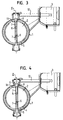
- FIG. 4 third variant of an inventive Blocking arrangement is largely consistent with the other two variants match.
- separate storage bins 9 are again provided, which, however, have a conical shape. The functioning is also described here as for the first variant.
- FIG. 5 shows a butterfly valve 2, which in its surrounding the axis of rotation II central region 12 has a greater thickness d 1 than in the two adjoining areas 13.
- the thickness d 1 of the central region 12 is selected to be correspondingly large.
- the two adjoining regions 13 have a thickness d 2 which only has to satisfy strength considerations and is therefore lower. The mass of the butterfly valve 2 is thereby reduced.
- the reduced thickness d 2 of the shut-off flap 2 in the regions 13 is made such that a type Z-shape of the shut-off flap 2 results in plan view in the direction of the axis of rotation II. That is, the withdrawal in the strength of the butterfly valve 2 is made once on one side and once on the other side of the butterfly valve 2, which thereby receives a two-fold point symmetry about its axis of rotation II. This results in a uniform weight distribution and a symmetrical stop on the half-shells. 5
- the butterfly valve 2 in the metal injection molding process be prepared. This gives you a high dimensional accuracy at relatively low production costs.
- shut-off invention All variants of the shut-off invention are characterized due to a good sealing function and low noise level. In addition, the production is inexpensive and inexpensive.
Abstract
Description
Die vorliegende Erfindung betrifft eine Absperranordnung zum Absperren eines Fluidstroms, insbesondere Abgasstroms einer Kraftfahrzeugabgasanlage, mit einem Gehäuse, einer in dem Gehäuse angeordneten, um eine quer zur Strömungsrichtung verlaufende Achse drehbaren Absperrklappe und Mitteln zur Betätigung der AbsperrklappeThe present invention relates to a shut-off device for shutting off a fluid flow, in particular exhaust gas flow of a motor vehicle exhaust system, with a housing, one arranged in the housing, around a Shut-off flap rotatable transverse to the direction of flow and means for actuating the butterfly valve
Abgasklappen in Kraftfahrzeugabgasanlagen sind seit langem bekannt und werden beispielsweise zum Absperren eines Zweiges der Abgasanlage eingesetzt. Die Betätigung erfolgt üblicherweise über eine Unterdruckdose. Ein Problem bei derartigen Abgasklappen besteht darin, dass Störgeräusche wie Zischeln oder Zwitschern entstehen können.Exhaust flaps in automotive exhaust systems have long been known and become, for example, shut off a branch of the exhaust system used. The actuation usually takes place via a vacuum box. A problem with such exhaust valves is that noise like hissing or chirping.
Der Erfindung liegt die Aufgabe zugrunde, eine Absperranordnung der eingangs genannten Art anzugeben, durch welche diese Probleme vermieden werden können.The invention is based on the object, a shut-off the to specify the type mentioned by which avoided these problems can be.
Diese Aufgabe wird dadurch gelöst, dass an der Innenwand des Gehäuses mindestens ein nach innen vorstehender Anschlag für die Absperrklappe vorgesehen ist, dessen Kontur einem Umfangsabschnitt der Absperrklappe entspricht, so dass die Absperrklappe in Sperrstellung mit einem Randbereich an dem Anschlag anliegt. This object is achieved in that on the inner wall of the housing at least one inwardly projecting stop for the butterfly valve is provided, whose contour is a peripheral portion of the butterfly valve corresponds so that the butterfly valve in blocking position with a border area abuts against the stop.
Durch das Vorsehen eines Anschlages der genannten Art entsteht im geschlossenen Zustand ein langer, labyrinthartiger Dichtspalt zwischen der Absperrklappe und dem Gehäuse. Auf diese Weise können Störgeräusche wie Zischeln oder Zwitschern weitgehend unterdrückt werden. Darüber hinaus ist ein guter Verschluss gewährleistet.By providing a stop of the type mentioned arises in closed state a long, labyrinthine sealing gap between the butterfly valve and the housing. In this way, noise can be heard like hissing or chirping are largely suppressed. About that In addition, a good closure is guaranteed.
Ein derartiger Anschlag ist bevorzugt an zwei einander gegenüberliegenden Seiten des Gehäuses vorgesehen, und die Anschläge erstrecken sich bevorzugt jeweils von einem Drehpunkt der Absperrklappe zum anderen, also jeweils im Wesentlichen über die Hälfte des Umfangs der Absperrklappe. Dies bewirkt einen labyrinthartigen Dichtspalt über den gesamten Umfang der Absperrklappe und ermöglicht dadurch eine besonders gute Unterdrückung von Störgeräuschen.Such a stop is preferably at two opposite Side of the housing provided, and the stops extend preferably in each case from one pivot point of the butterfly valve to the other, So in each case substantially over half of the circumference of the butterfly valve. This causes a labyrinthine sealing gap over the entire Scope of the butterfly valve and thus allows a particularly good Suppression of noise.
Die Anschläge können derart angeordnet sein, dass die Absperrklappe in Anschlagstellung einen Winkel von 90° mit der Strömungsrichtung einschließt. Die Anschläge können aber auch so angeordnet sein, dass die Absperrklappe mit der Strömungsrichtung einen kleineren Winkel einschließt, insbesondere ca. 80° bis ca. 85°. Ein kleinerer Winkel hat den Vorteil, dass der Stellweg geringer ist.The stops can be arranged such that the butterfly valve in Stop position forms an angle of 90 ° with the flow direction. The attacks can also be arranged so that the Shut-off valve with the flow direction includes a smaller angle, in particular about 80 ° to about 85 °. A smaller angle has that Advantage that the travel is lower.
Das Gehäuse der Absperranordnung kann ein- oder mehrteilig ausgebildet sein. Bevorzugt ist das Gehäuse durch ein Rohrstück gebildet. Dies ist von der Herstellung unaufwändig.The housing of the shut-off can be formed one or more parts be. Preferably, the housing is formed by a pipe section. This is from the production is easy.
Ebenfalls unaufwändig in der Herstellung ist die Ausbildung der Anschläge je durch einen Rohrausschnitt, also insbesondere als Halbschalen, bevorzugt hergestellt als Stanzprägeteil. Diese können auch besonders gut an ein rohrförmiges Gehäuse angepasst werden. Also inexpensive in the production is the formation of the attacks each by a pipe cut, ie in particular as half-shells, preferably produced as a stamped stamped part. These can also be especially good adapted to a tubular housing.
Die Absperrklappe ist bevorzugt beidseitig gelagert, insbesondere durch je eine Halbwelle. Dies erhöht die Funktionssicherheit der Absperranordnung.The butterfly valve is preferably mounted on both sides, in particular by each a half wave. This increases the reliability of the shut-off.
Nach einer weiteren Ausgestaltung der Erfindung weist die Absperrklappe eine solche Stärke auf, dass die Halbwellen jeweils in eine Ausnehmung in der Absperrklappe eingesteckt werden können. Auch dies ist herstellungstechnisch günstig. Zur Fixierung der Halbwellen kann insbesondere eine Laser-Durchstechnaht verwendet werden.According to a further embodiment of the invention, the butterfly valve on such a strength that the half-waves each in a recess in the butterfly valve can be inserted. This too is manufacturing technology Cheap. For fixing the half-waves can in particular a Laser passage can be used.
Bevorzugt weist die Absperrklappe im ihre Drehachse umgebenden mittleren Bereich eine größere Stärke auf als in den beidseits darin anschließenden Bereichen. Dadurch kann einerseits eine ausreichende Stärke zur Einbringung der Ausnehmungen für die Halbwellen zur Verfügung gestellt und anderseits die Masse der Klappe gering gehalten werden.Preferably, the butterfly valve in the surrounding axis of rotation axis Area a greater strength than in the two-sided adjoining Areas. This can on the one hand a sufficient strength for Insertion of the recesses for the half-waves provided and on the other hand, the mass of the flap are kept low.
Vorteilhaft ist es dabei, wenn die Bereiche verringerter Stärke mit zweifacher Punktsymmetrie zur Drehachse ausgebildet sind, so dass sich bei der Draufsicht in Richtung der Drehachse eine Art Z-Form der Absperrklappe ergibt. Es ergibt sich einerseits eine gleichmäßige Gewichtsverteilung und andererseits ein symmetrischer Anschlag der Absperrklappe.It is advantageous if the areas of reduced strength with two times Point symmetry are formed to the axis of rotation, so that in the Top view in the direction of the axis of rotation a kind of Z-shape of the butterfly valve results. On the one hand results in a uniform weight distribution and on the other hand a symmetrical stop of the butterfly valve.
Um eine einfache Zentrierung der Absperrklappe im Gehäuse zu erreichen, können die Halbwellen nach einer weiteren Ausgestaltung der Erfindung je einen Anschlag aufweisen. Zusätzliche Zentriermittel sind dadurch entbehrlich.To achieve a simple centering of the butterfly valve in the housing, can the half-waves according to a further embodiment of the invention each have a stop. Additional centering means are dispensable.
Die Absperrklappe kann ebenfalls ein- oder mehrteilig ausgebildet sein. Die Herstellung der Abgasklappen kann dabei vorteilhaft im Metallspritzgussverfahren erfolgen, wobei die Herstellung der Ausnehmungen für die Halbwellen insbesondere in den Spritzgussprozess integriert ist. Eine zusätzliche mechanische Bearbeitung kann dann entfallen. Diese Herstellung ist kostengünstig und führt zu einer hohen Maßgenauigkeit der Abgasklappe.The butterfly valve may also be formed in one or more parts. The production of the exhaust valves can be advantageous in the metal injection molding process take place, wherein the production of the recesses for the Half-waves is integrated in particular in the injection molding process. A additional mechanical processing can then be omitted. This production is inexpensive and leads to a high dimensional accuracy of Exhaust flap.
Die Lager für die Halbwellen sind bevorzugt aus Graphit, mit oder ohne Gewebeverstärkung, und/oder aus keramischen oder metallischen Lagerwerkstoffen gebildet. Derartige Werkstoffe haben sich als besonders geeignet herausgestellt.The bearings for the half-waves are preferably made of graphite, with or without Fabric reinforcement, and / or of ceramic or metallic bearing materials educated. Such materials have proven to be particularly suitable exposed.
In bestimmen Anwendungsfällen vorteilhaft ist die Verwendung eines separaten Lagerelementes für die Lagerung der Absperrklappe. Dabei kann das separate Lagerelement bevorzugt eine rotationssymmetrische Kontur aufweisen. Die Montage ist dadurch vereinfacht.In certain applications advantageous is the use of a separate bearing element for the storage of the butterfly valve. there the separate bearing element can preferably be a rotationally symmetrical Contour. The assembly is simplified.
Ebenfalls in bestimmten Anwendungsfällen vorteilhaft ist eine konische Ausbildung der Lager.Also advantageous in certain applications is a conical Training of the camps.
Nicht beschränkende Ausführungsbeispiel der Erfindung sind in den Zeichnungen dargestellt und werden nachfolgend beschrieben. Es zeigen, jeweils in schematischer Darstellung:
- Fig. 1
- eine perspektivische, teilweise geschnittene Darstellung einer erfindungsgemäßen Absperranordnung,
- Fig. 2
- einen Schnitt durch die Absperranordnung von Fig. 1,
- Fig. 3
- einen Querschnitt durch eine zweite Variante einer erfindungsgemäßen Absperranordnung,
- Fig. 4
- einen Querschnitt durch noch eine Variante einer erfindungsgemäßen Absperranordnung, und
- Fig. 5
- einen Schnitt durch einen Teil noch einer Variante einer erfindungsgemäßen Absperranordnung.
- Fig. 1
- a perspective, partially sectioned view of a shut-off arrangement according to the invention,
- Fig. 2
- a section through the shut-off of Fig. 1,
- Fig. 3
- a cross section through a second variant of a shut-off invention,
- Fig. 4
- a cross section through yet another variant of a shut-off invention, and
- Fig. 5
- a section through a part still a variant of a shut-off arrangement according to the invention.
Die in den Fig. 1 und 2 dargestellte Absperranordnung umfasst ein rohrförmiges
Gehäuse 1, in welchem eine Absperrklappe 2 um eine quer zur
Strömungsrichtung I verlaufende Achse II drehbar gelagert ist. Seitlich am
Gehäuse 1 ist eine Unterdruckdose 3 angebracht, über welche die Absperrklappe
2 betätigbar ist.The shut-off arrangement shown in FIGS. 1 and 2 comprises a tubular
Housing 1, in which a
An der Innenwand 4 des Gehäuses 1 sind zwei Halbschalen 5 angeordnet,
die als Anschlag für die Absperrklappe 2 dienen. Die Halbschalen 5 sind
hierfür jeweils auf einander gegenüberliegenden Seiten des Gehäuses 1
angeordnet und in Strömungsrichtung I zueinander versetzt. Die Absperrklappe
2 schlägt dadurch in Schließstellung gleichzeitig an beiden Halbschalen
5 an.On the inner wall 4 of the housing 1, two half-
Die Anordnung der Halbschalen 5 kann so gewählt sein, dass die Absperrklappe
2 in Schließstellung einen Winkel von 90° zur Strömungsrichtung
I einschließt. Sie kann aber auch so gewählt sein, dass der Winkel
kleiner ist als 90°, insbesondere zwischen ca. 80° und ca. 85° beträgt.
Sowohl das Gehäuse 1 als auch die Absperrklappe 2 können ein- oder
mehrteilig sein.The arrangement of the half-
Die Absperrklappe 2 ist im Gehäuse 1 beidseitig gelagert. Hierfür weist die
Absperrklappe 2 auf zwei voneinander abgewandten Seiten in ihrem Rand
je ein Sackloch 6 auf, in welches je eine Halbwelle 7 eingesteckt ist. Die
Halbwellen 7 sind in den Sacklöchern 6 jeweils bevorzugt durch eine
Laser-Durchstechnaht befestigt. Die Halbwellen 7 sind über Durchtrittsöffnungen
8 aus dem Gehäuse 1 herausgeführt und durchgreifen außerhalb
des Gehäuses 1 angeordnete Lagerbuchsen 9. Die Lager bestehen
beispielsweise aus Graphit, mit oder ohne Gewebeverstärkung, und/oder
aus keramischen oder metallischen Lagerwerkstoffen. Die Lagerbuchsen 9
weisen außerdem eine rotationssymmetrische Kontur auf.The
An der in den Fig. 1 und 2 oben dargestellten Halbwelle 7 ist ein Betätigungsstößel
10 der Unterdruckdose 3 angelenkt. Auf diese Weise ist die
obere Halbwelle 7 um die Achse II verdrehbar, und mit ihr die Absperrklappe
2 und die untere Halbwelle 7. Schließlich weisen die beiden Halbwellen
7 noch jeweils einen Anschlag 11 auf, über welche die Absperrklappe
2 im Gehäuse 1 zentriert wird.At the half-
Die Funktion der dargestellten Absperranordnung ist folgendermaßen: In
Öffnungsstellung befindet sich die Absperrklappe 2 in der in den Fig. 1
und 2 dargestellten Stellung, in welcher sich die Ebene der Absperrklappe
2 parallel zur Strömungsrichtung I erstreckt. Der Durchflussquerschnitt
des Gehäuses 1 wird dadurch freigegeben. Durch Betätigen der Unterdruckdose
3 kann die Absperrklappe 2 um die Achse II verdreht werden,
bis ihre Randbereiche an den beiden Halbschalen 5 anschlagen. In dieser
Stellung ist der Durchflussquerschnitt des Gehäuses 1 verschlossen. Es
besteht dabei ein langer, labyrinthartiger Dichtspalt zwischen der Absperrklappe
2 und den Halbschalen 5 sowie der Innenwand 4 des Gehäuses
1, wodurch das Entstehen von Störgeräuschen wie Zischeln oder
Zwitschern weitgehend verhindert wird.The function of the shut-off sequence shown is as follows: In
Opening position is the
Die in Fig. 3 dargestellte Variante einer erfindungsgemäßen Absperranordnung stimmt weitgehend mit der Variante der Fig. 1 und 2 überein. The variant shown in Fig. 3 of a shut-off arrangement according to the invention is largely consistent with the variant of FIGS. 1 and 2.
Ein wesentlicher Unterschied besteht darin, dass hier keine separate
Lagerbuchsen zur Lagerung der beiden Halbwellen 7 vorgesehen sind. Die
Funktionsweise ist dieselbe wie zuvor beschrieben.One major difference is that there is no separate one here
Bearing bushes for the storage of the two half-
Auch die in Fig. 4 dargestellte dritte Variante einer erfindungsgemäßen
Absperranordnung stimmt weitgehend mit den beiden anderen Varianten
überein. Bei dieser Variante sind wieder separate Lagerbuchen 9 vorgesehen,
die allerdings eine konische Form aufweisen. Die Funktionsweise ist
auch hier wie zur ersten Variante beschrieben.Also shown in Fig. 4 third variant of an inventive
Blocking arrangement is largely consistent with the other two variants
match. In this variant,
Die in Figur 5 dargestellte Variante zeigt eine Absperrklappe 2, die in
ihrem die Drehachse II umgebenden mittleren Bereich 12 eine größere
Stärke d1 aufweist als in den beiden daran anschließenden Bereichen 13.
Im mittleren Bereich 12 der Absperrklappe 2 sind wiederum die Sacklöcher
6 für die beiden Halbwellen 7 eingebracht. Die Stärke d1 des mittleren
Bereiches 12 ist entsprechend groß gewählt. Die beiden daran anschließenden
Bereiche 13 weisen dagegen eine Stärke d2 auf, die lediglich
Festigkeitsgesichtspunkten genügen muss und daher geringer ist. Die
Masse der Absperrklappe 2 ist dadurch verringert.The variant shown in Figure 5 shows a
Wie man in Figur 5 außerdem sieht, ist die verringerte Stärke d2 der Absperrklappe
2 in den Bereichen 13 so vorgenommen, dass sich in Draufsicht
in Richtung der Drehachse II eine Art Z-Form der Absperrklappe 2
ergibt. Das heißt, die Rücknahme in der Stärke der Absperrklappe 2 ist
einmal auf der einen Seite und einmal auf der anderen Seite der Absperrklappe
2 vorgenommen, die dadurch eine zweifache Punktsymmetrie um
ihre Drehachse II erhält. Dadurch ergibt sich eine gleichmäßige Gewichtsverteilung
und ein symmetrischer Anschlag an den Halbschalen 5. As can also be seen in FIG. 5, the reduced thickness d 2 of the shut-off
Bei allen Ausführungsvarianten kann die Absperrklappe 2 im Metallspritzgussverfahren
hergestellt sein. Sie erhält dadurch eine hohe Maßgenauigkeit
bei verhältnismäßig geringen Herstellungskosten.In all variants, the
Alle Varianten der erfindungsgemäßen Absperranordnung zeichnen sich durch eine gute Dichtfunktion und geringe Geräuschentwicklung aus. Zudem ist die Herstellung unaufwändig und kostengünstig möglich. All variants of the shut-off invention are characterized due to a good sealing function and low noise level. In addition, the production is inexpensive and inexpensive.
- 11
- Gehäusecasing
- 22
- Absperrklappebutterfly valve
- 33
- UnterdruckdoseVacuum unit
- 44
- Innenwand von 1Inner wall of 1
- 55
- Halbschalehalf shell
- 66
- Sacklochblind
- 77
- Halbwellehalf-wave
- 88th
- DurchtrittsöffnungThrough opening
- 99
- Lagerbuchsebearing bush
- 1010
- Betätigungsstößelactuating ram
- 1111
- Anschlagattack
- 1212
- mittlerer Bereich von 2middle range of 2
- 1313
- Bereich von 2Range of 2
- II
- Strömungsrichtungflow direction
- IIII
- Drehachseaxis of rotation
- d1 d 1
- Stärke von 12Strength of 12
- d2 d 2
- Stärke von 13Strength of 13
Claims (10)
dadurch gekennzeichnet, dass an der Innenwand (4) des Gehäuses (1) mindestens ein nach innen vorstehender Anschlag (5) für die Absperrklappe (2) vorgesehen ist, dessen Kontur einem Umfangsabschnitt der Absperrklappe (2) entspricht, so dass die Absperrklappe (2) in Sperrstellung mit einem Randbereich an dem Anschlag (5) anliegt.Shut-off arrangement for shutting off a fluid flow, in particular exhaust gas flow of a motor vehicle exhaust system, having a housing (1), a shut-off flap (2) which is rotatable in the housing (1) and rotatable about an axis (II) transverse to the flow direction (1) and means (3) for actuating the butterfly valve,
characterized in that on the inner wall (4) of the housing (1) at least one inwardly projecting stop (5) for the butterfly valve (2) is provided whose contour corresponds to a peripheral portion of the butterfly valve (2), so that the butterfly valve (2 ) abuts in the blocking position with an edge region on the stop (5).
dadurch gekennzeichnet, dass an zwei einander gegenüberliegenden Innenseiten (4) des Gehäuses (1) ein solcher Anschlag (5) vorgesehen ist und/oder dass sich die Anschläge (5) jeweils von einem Drehpunkt der Absperrklappe (2) zum anderen erstrecken.Shut-off arrangement according to claim 1,
characterized in that on two opposite inner sides (4) of the housing (1) such a stop (5) is provided and / or that the stops (5) each extend from a pivot point of the butterfly valve (2) to the other.
dadurch gekennzeichnet, dass der oder die Anschläge (5) derart angeordnet sind, dass die Absperrklappe (2) in Anschlagstellung einen Winkel von 90° mit der Strömungsrichtung (I) einschließt, oder derart, dass die Absperrklappe (2) in Anschlagstellung einen Winkel kleiner 90°, insbesondere ca. 80° bis ca. 85° mit der Strömungsrichtung (I) einschließt.Shut-off arrangement according to one of the preceding claims,
characterized in that the one or more stops (5) are arranged such that the shut-off flap (2) in stop position forms an angle of 90 ° with the flow direction (I), or such that the shut-off flap (2) in stop position an angle smaller 90 °, in particular about 80 ° to about 85 ° with the flow direction (I) includes.
dadurch gekennzeichnet, dass das Gehäuse (1) ein- oder mehrteilig ausgebildet ist und/oder dass das Gehäuse (1) durch ein Rohrstück gebildet ist.Shut-off arrangement according to one of the preceding claims,
characterized in that the housing (1) is formed in one or more parts and / or that the housing (1) is formed by a piece of pipe.
dadurch gekennzeichnet, dass der oder die Anschläge (5) je durch einen Rohrausschnitt gebildet sind, insbesondere durch Halbschalen, bevorzugt hergestellt als Stanzprägeteil.Shut-off arrangement according to one of the preceding claims,
characterized in that the one or more stops (5) are each formed by a pipe cut, in particular by half shells, preferably prepared as a stamped punched part.
dadurch gekennzeichnet, dass die Absperrklappe (2) beidseitig gelagert ist, insbesondere durch je eine Halbwelle (7).Shut-off arrangement according to one of the preceding claims,
characterized in that the shut-off flap (2) is mounted on both sides, in particular by a respective half-wave (7).
dadurch gekennzeichnet, dass die Absperrklappe (2) eine solche Stärke aufweist, dass die Halbwellen (7) jeweils in eine Ausnehmung (6) in der Absperrklappe (2) eingesteckt werden können und/oder dass die Absperrklappe (2) im ihre Drehachse (II) umgebenden mittleren Bereich (12) eine größere Stärke (d1) aufweist als in den beidseits daran anschließenden Bereichen (13), wobei die Bereiche (13) verringerter Stärke (d2) bevorzugt mit zweifacher Punktsymmetrie zur Drehachse (II) ausgebildet sind, so dass sich bei Draufsicht in Richtung der Drehachse (II) eine Art Z-Form der Absperrklappe (2) ergibt.Shut-off arrangement according to one of the preceding claims,
characterized in that the butterfly valve (2) has such a strength that the half-waves (7) in each case in a recess (6) in the butterfly valve (2) can be inserted and / or that the butterfly valve (2) in its axis of rotation (II ) surrounding central region (12) has a greater thickness (d 1 ) than in the regions (13) adjoining on both sides, the regions (13) of reduced thickness (d 2 ) preferably having twice the point symmetry with respect to the axis of rotation (II), so that in plan view in the direction of the axis of rotation (II) results in a kind of Z-shape of the butterfly valve (2).
dadurch gekennzeichnet, dass die Halbwellen (7) an der Absperrklappe (2) mittels einer Laser-Durchstechnaht befestigt sind und/oder dass die Halbwellen (7) je einen Anschlag (11) zur Zentrierung der Absperrklappe (2) im Gehäuse (1) aufweisen.Shut-off arrangement according to one of the preceding claims,
characterized in that the half-shafts (7) are attached to the butterfly valve (2) by means of a laser Durchstechnaht and / or that the half-shafts (7) each have a stop (11) for centering the butterfly valve (2) in the housing (1) ,
dadurch gekennzeichnet, dass die Absperrklappe (2) ein- oder mehrteilig ausgebildet ist und/oder dass die Absperrklappe (2) im Metallspritzgussverfahren hergestellt ist.Shut-off arrangement according to one of the preceding claims,
characterized in that the shut-off flap (2) is formed in one or more parts and / or that the shut-off flap (2) is produced by the metal injection molding process.
dadurch gekennzeichnet, dass die Lager für die Halbwellen (7) aus Graphit, mit oder ohne Gewebeverstärkung, und/oder aus keramischen oder metallischen Lagerwerkstoffen bestehen und/oder dass ein separates Lagerelement (9) für die Lagerung der Absperrklappe (2) vorgesehen ist, wobei das Lagerelement (9) insbesondere eine rotationssymmetrische Kontur und/oder eine konische Form aufweist.Shut-off arrangement according to one of the preceding claims,
characterized in that the bearings for the half-shafts (7) consist of graphite, with or without fabric reinforcement, and / or of ceramic or metallic bearing materials and / or that a separate bearing element (9) for the storage of the butterfly valve (2) is provided, wherein the bearing element (9) in particular has a rotationally symmetrical contour and / or a conical shape.
Applications Claiming Priority (2)
| Application Number | Priority Date | Filing Date | Title |
|---|---|---|---|
| DE20311260U DE20311260U1 (en) | 2003-07-22 | 2003-07-22 | Shut-off arrangement for shutting off a fluid flow |
| DE20311260U | 2003-07-22 |
Publications (1)
| Publication Number | Publication Date |
|---|---|
| EP1503062A1 true EP1503062A1 (en) | 2005-02-02 |
Family
ID=33495286
Family Applications (1)
| Application Number | Title | Priority Date | Filing Date |
|---|---|---|---|
| EP04017191A Withdrawn EP1503062A1 (en) | 2003-07-22 | 2004-07-21 | Device for closing a fluid stream |
Country Status (2)
| Country | Link |
|---|---|
| EP (1) | EP1503062A1 (en) |
| DE (1) | DE20311260U1 (en) |
Cited By (3)
| Publication number | Priority date | Publication date | Assignee | Title |
|---|---|---|---|---|
| WO2006136213A1 (en) * | 2005-06-20 | 2006-12-28 | Emcon Technologies Germany (Augsburg) Gmbh | Valve, especially for a motor vehicle exhaust system |
| WO2014016161A1 (en) * | 2012-07-24 | 2014-01-30 | Friedrich Boysen Gmbh & Co. Kg | Bearing system for a shaft |
| DE102021134312A1 (en) | 2021-12-22 | 2023-06-22 | Wagner Group Gmbh | Fluid for reversing the direction of flow |
Families Citing this family (1)
| Publication number | Priority date | Publication date | Assignee | Title |
|---|---|---|---|---|
| DE102011107024B4 (en) * | 2011-07-14 | 2019-02-07 | Friedrich Boysen Gmbh & Co. Kg | CONTROL DEVICE and method of making the same |
Citations (9)
| Publication number | Priority date | Publication date | Assignee | Title |
|---|---|---|---|---|
| GB567751A (en) * | 1942-02-24 | 1945-03-01 | William Arnold Horrocks | Improvements in exhaust-pipes for internal-combustion engines |
| GB1014575A (en) * | 1964-07-03 | 1965-12-31 | Crane Ltd | Butterfly type of fluid control valves |
| US3661171A (en) * | 1970-05-12 | 1972-05-09 | Xomox Corp | Butterfly valve |
| US4491106A (en) * | 1982-11-29 | 1985-01-01 | Morris George Q | Throttle configuration achieving high velocity channel at partial opening |
| US4572478A (en) * | 1982-11-29 | 1986-02-25 | Vdo Adolf Schindling Ag | Throttle-valve connection piece |
| FR2606115A1 (en) * | 1986-10-31 | 1988-05-06 | Peugeot | Butterfly valve particularly for a motor vehicle, and its application to a carburetter |
| GB2245931A (en) * | 1990-07-10 | 1992-01-15 | Rover Group | I.c. engine air intake throttle body |
| US5669350A (en) * | 1993-09-02 | 1997-09-23 | Filterwerk Mann & Hummel Gmbh | Throttle device |
| US6138640A (en) * | 1998-06-30 | 2000-10-31 | Aisan Kogyo Kabushiki Kaisha | Intake control valve device for internal combustion engine |
Family Cites Families (17)
| Publication number | Priority date | Publication date | Assignee | Title |
|---|---|---|---|---|
| DE922800C (en) * | 1952-12-23 | 1955-01-24 | Kloeckner Humboldt Deutz Ag | Throttle valve in a spherical housing of the exhaust line to increase the braking effect |
| DE1991832U (en) * | 1968-05-31 | 1968-08-14 | Trox Gmbh Geb | THROTTLE VALVE FOR IN PARTICULAR HIGH PRESSURE SYSTEMS. |
| DE3113004A1 (en) * | 1981-04-01 | 1982-10-21 | Schunk & Ebe Gmbh, 6301 Heuchelheim | Sliding body |
| DE8120908U1 (en) * | 1981-07-16 | 1981-10-08 | Bowa GmbH, Apparate- und Behälterbau, 8261 Aschau | PIPE CONNECTOR WITH A PIVOTING EXHAUST VALVE |
| DE8129546U1 (en) * | 1981-10-09 | 1982-03-04 | Mtu Motoren- Und Turbinen-Union Friedrichshafen Gmbh, 7990 Friedrichshafen | "STORAGE FOR A LOCKING PART" |
| DE3802243A1 (en) * | 1988-01-27 | 1989-08-10 | Daimler Benz Ag | STORAGE OF A THROTTLE VALVE SHAFT IN THE HOUSING OF AN EXHAUST PIPE |
| DE3920189A1 (en) * | 1988-07-01 | 1990-01-04 | Luk Lamellen & Kupplungsbau | Fluid coupling such as a Föttinger coupling or torque converter |
| GB9200339D0 (en) * | 1992-01-08 | 1992-02-26 | Btr Plc | Valve disc and drive shaft assembly |
| DE4305123C2 (en) * | 1993-02-19 | 1995-01-26 | Pierburg Gmbh | Arrangement of a throttle valve |
| US5427137A (en) * | 1993-12-15 | 1995-06-27 | Bowen; James H. | Fluid shut off valve and fill level indication |
| DE19500501A1 (en) * | 1994-06-28 | 1996-01-04 | Schatz Thermo Engineering | Method of controlling load changes of IC engine by valves |
| DE9419537U1 (en) * | 1994-12-06 | 1995-02-02 | Eberspaecher J | Exhaust flap arrangement |
| DE19500475C2 (en) * | 1995-01-10 | 2001-09-27 | Schatz Thermo Gastech Gmbh | Shut-off or throttle valve with rotatable valve flap |
| DE19524510A1 (en) * | 1995-07-05 | 1997-01-09 | Klein Schanzlin & Becker Ag | Fluid-lubricated plain bearing |
| DE20002784U1 (en) * | 2000-02-16 | 2000-07-13 | Albert Handtmann Metallguswerk | Throttle valve arranged on a shaft |
| DE10140410A1 (en) * | 2001-08-23 | 2003-03-13 | Siemens Ag | throttle assembly |
| DE10151605A1 (en) * | 2001-10-18 | 2003-05-08 | Euroflamm Gmbh | Slide |
-
2003
- 2003-07-22 DE DE20311260U patent/DE20311260U1/en not_active Expired - Lifetime
-
2004
- 2004-07-21 EP EP04017191A patent/EP1503062A1/en not_active Withdrawn
Patent Citations (9)
| Publication number | Priority date | Publication date | Assignee | Title |
|---|---|---|---|---|
| GB567751A (en) * | 1942-02-24 | 1945-03-01 | William Arnold Horrocks | Improvements in exhaust-pipes for internal-combustion engines |
| GB1014575A (en) * | 1964-07-03 | 1965-12-31 | Crane Ltd | Butterfly type of fluid control valves |
| US3661171A (en) * | 1970-05-12 | 1972-05-09 | Xomox Corp | Butterfly valve |
| US4491106A (en) * | 1982-11-29 | 1985-01-01 | Morris George Q | Throttle configuration achieving high velocity channel at partial opening |
| US4572478A (en) * | 1982-11-29 | 1986-02-25 | Vdo Adolf Schindling Ag | Throttle-valve connection piece |
| FR2606115A1 (en) * | 1986-10-31 | 1988-05-06 | Peugeot | Butterfly valve particularly for a motor vehicle, and its application to a carburetter |
| GB2245931A (en) * | 1990-07-10 | 1992-01-15 | Rover Group | I.c. engine air intake throttle body |
| US5669350A (en) * | 1993-09-02 | 1997-09-23 | Filterwerk Mann & Hummel Gmbh | Throttle device |
| US6138640A (en) * | 1998-06-30 | 2000-10-31 | Aisan Kogyo Kabushiki Kaisha | Intake control valve device for internal combustion engine |
Cited By (4)
| Publication number | Priority date | Publication date | Assignee | Title |
|---|---|---|---|---|
| WO2006136213A1 (en) * | 2005-06-20 | 2006-12-28 | Emcon Technologies Germany (Augsburg) Gmbh | Valve, especially for a motor vehicle exhaust system |
| WO2014016161A1 (en) * | 2012-07-24 | 2014-01-30 | Friedrich Boysen Gmbh & Co. Kg | Bearing system for a shaft |
| DE102012212998B4 (en) | 2012-07-24 | 2023-09-07 | Friedrich Boysen Gmbh & Co. Kg | Bearing system for a shaft |
| DE102021134312A1 (en) | 2021-12-22 | 2023-06-22 | Wagner Group Gmbh | Fluid for reversing the direction of flow |
Also Published As
| Publication number | Publication date |
|---|---|
| DE20311260U1 (en) | 2004-12-02 |
Similar Documents
| Publication | Publication Date | Title |
|---|---|---|
| EP2229550B1 (en) | Exhaust gas recirculation valve for a motor vehicle | |
| EP1909005B1 (en) | Throttle valve unit for a combustion engine | |
| EP2728156B1 (en) | Control device for a combustion engine | |
| DE102006021185A1 (en) | Locking cap for exhaust gas turbocharger, has actuation arm with notch enclosing opening of arm, raised region engaged to notch, and stop formed in region radially outside of notch for sealing cap on actuation arm | |
| EP3012445A1 (en) | Control device for a combustion engine | |
| DE102015209823A1 (en) | actuator | |
| DE102008034341A1 (en) | Double flap valve arrangement for exhaust gas stream in exhaust system of internal combustion engine of motor vehicle, has plates arranged section wise transverse to flow direction in open position of arrangement | |
| EP3615787B1 (en) | Valve for an internal combustion engine | |
| DE2849281C2 (en) | ||
| EP2079911B1 (en) | Throttle flap connecting piece | |
| EP1936151B1 (en) | Method for manufacturing a device for controlling the throughflow of a gaseous or liquid medium | |
| EP1503062A1 (en) | Device for closing a fluid stream | |
| EP2653710B1 (en) | Valve device for a combustion engine | |
| DE102017120003A1 (en) | Air vents for a vehicle | |
| WO2006136213A1 (en) | Valve, especially for a motor vehicle exhaust system | |
| DE102007025516A1 (en) | Ball valve for blocking off and controlled opening of pipes has a casing with inlets and outlets, a valve ball with inlet openings and an outlet opening and an adjusting device | |
| DE102012224093A1 (en) | Valve device for a motor vehicle | |
| WO2021144183A1 (en) | Valve device for an internal combustion engine | |
| DE102011017452A1 (en) | Actuator device used as exhaust gas re-conducting valve in motor vehicle, has motor that is connected to recess portion of driving element | |
| DE10330225B4 (en) | Valve device for an internal combustion engine | |
| EP1062445A1 (en) | Thermal safety valve for automatically shutting off pipes | |
| DE112017007999T5 (en) | Valve with rattle protection, exhaust pipe with such a valve and method for producing such a valve | |
| DE10334475B4 (en) | Valve system for an internal combustion engine | |
| EP1561996B1 (en) | Shut-Off Device for a Gas Conveying Tube | |
| EP1649200B1 (en) | Subunit for an additional control valve device used for an intake pipe of a reciprocating internal combustion engine |
Legal Events
| Date | Code | Title | Description |
|---|---|---|---|
| PUAI | Public reference made under article 153(3) epc to a published international application that has entered the european phase |
Free format text: ORIGINAL CODE: 0009012 |
|
| AK | Designated contracting states |
Kind code of ref document: A1 Designated state(s): AT BE BG CH CY CZ DE DK EE ES FI FR GB GR HU IE IT LI LU MC NL PL PT RO SE SI SK TR |
|
| AX | Request for extension of the european patent |
Extension state: AL HR LT LV MK |
|
| 17P | Request for examination filed |
Effective date: 20050407 |
|
| 17Q | First examination report despatched |
Effective date: 20050513 |
|
| AKX | Designation fees paid |
Designated state(s): CZ DE FR GB IT |
|
| STAA | Information on the status of an ep patent application or granted ep patent |
Free format text: STATUS: THE APPLICATION IS DEEMED TO BE WITHDRAWN |
|
| 18D | Application deemed to be withdrawn |
Effective date: 20060324 |