EP1502809B1 - A neck rest for the seat of an automobile - Google Patents
A neck rest for the seat of an automobile Download PDFInfo
- Publication number
- EP1502809B1 EP1502809B1 EP04015049A EP04015049A EP1502809B1 EP 1502809 B1 EP1502809 B1 EP 1502809B1 EP 04015049 A EP04015049 A EP 04015049A EP 04015049 A EP04015049 A EP 04015049A EP 1502809 B1 EP1502809 B1 EP 1502809B1
- Authority
- EP
- European Patent Office
- Prior art keywords
- support portion
- neck rest
- locking
- releasing
- guiding
- Prior art date
- Legal status (The legal status is an assumption and is not a legal conclusion. Google has not performed a legal analysis and makes no representation as to the accuracy of the status listed.)
- Expired - Lifetime
Links
- 230000000903 blocking effect Effects 0.000 claims description 27
- 238000006073 displacement reaction Methods 0.000 claims description 6
- 230000035939 shock Effects 0.000 claims description 5
- 230000000717 retained effect Effects 0.000 claims 1
- 230000001133 acceleration Effects 0.000 description 3
- 230000004913 activation Effects 0.000 description 2
- 208000027418 Wounds and injury Diseases 0.000 description 1
- 238000010521 absorption reaction Methods 0.000 description 1
- 230000006378 damage Effects 0.000 description 1
- 208000014674 injury Diseases 0.000 description 1
Images

Classifications
-
- B—PERFORMING OPERATIONS; TRANSPORTING
- B60—VEHICLES IN GENERAL
- B60N—SEATS SPECIALLY ADAPTED FOR VEHICLES; VEHICLE PASSENGER ACCOMMODATION NOT OTHERWISE PROVIDED FOR
- B60N2/00—Seats specially adapted for vehicles; Arrangement or mounting of seats in vehicles
- B60N2/80—Head-rests
- B60N2/806—Head-rests movable or adjustable
-
- B—PERFORMING OPERATIONS; TRANSPORTING
- B60—VEHICLES IN GENERAL
- B60N—SEATS SPECIALLY ADAPTED FOR VEHICLES; VEHICLE PASSENGER ACCOMMODATION NOT OTHERWISE PROVIDED FOR
- B60N2/00—Seats specially adapted for vehicles; Arrangement or mounting of seats in vehicles
- B60N2/80—Head-rests
- B60N2/888—Head-rests with arrangements for protecting against abnormal g-forces, e.g. by displacement of the head-rest
Definitions
- the invention relates to a neck rest for the seat of an automobile according to claim 1.
- DE 199 61 617 A1 , DE 199 51 966 A1 or DE 101 42 625 A1 have made known a neck rest which has a supporting member adapted to be advanced to the front on the head of the seat used, and a shock member which actuates it. When there is an impact onto the rear end of the vehicle the shock member is actuated and the supporting member is advanced to the front.
- the supporting member is mounted on the upholstering carrier via pivoting arms.
- the supporting member forms part of the neck rest upholstering which is composed of two components which are interconnected via joints.
- the shock member can interact with the supporting member via a pulling cable and be in communication with a releasing element.
- DE 102 08 620 which is the closest prior art describes a neck rest for automobile seats which has a fixed support portion as well as a second support portion for a movable upholstering portion which is movably supported by the first support portion.
- the second support portion is pivotally supported about a lower horizontal axis on the first support portion and an actuation device is formed by a spring which biases the second support portion.
- a controllable locking device retains the second support portion in the retracted position on the first support portion.
- a third support portion is slidably mounted on the second support portion between a lower and an upper position. The third support portion is biased to the upper position by means of a second spring.
- a controllable second locking device retains the third support portion in the lower position with second locking device being unlocked once the second support portion has reached a predetermined pivoting angle. Further, stop means are provided between the second and third support portions and the first support portion when the second and third support portions have arrived at their extracted positions, to prevent the latter from pivoting back.
- the structure described last is intended to achieve an optimum absorption of force with the sitting person not undergoing a risk of injury when there is a rear-end shock.
- the neck rest is also divided into a first and a second support portion in the invention, the first one being mounted on the seat by means of neck rest rods and the second one constituting the movable one.
- the first support portion mounts a first spring which has at least one leg which is rotationally supported by the second support portion and biases it away from the first support portion.
- the second support portion has a guiding element which is guided by a guideway of the first support portion in displacing the second support portion from the first position to the second one, and vice versa.
- a movable blocking element biased by a second spring on the first support portion automatically blocks the second support portion in its second position.
- a locking element is supported by the first support portion and is adapted to be moved between a locking and an unlocking position. In the locking position, it cooperates with a locking projection of the first support portion to lock the second support portion in the first position.
- a releasing element movably supported by the first support portion, when in a non-actuated position, blocks the locking element in the locking position.
- An actuation device acts on the releasing element to unlock the locking element when the releasing element is actuated.
- the cooperation between the guiding element and guideway and the displacement path of the spring leg of the first spring determine the path of the second support portion during the displacement from the first position to the second one, and vice versa.
- the leg of the first spring firstly constitutes the actuator for the second support element and secondly forms a mounting for the second support portion in the second position thereof, in which second position supporting means are provided via which an impact onto the upholstering part of the second support portion is cushioned.
- the components required for the displacement of the second support portion and its locking and supporting can be configured as being very simple and be assembled to be very compact.
- the releasing element can be selectively actuated in an electric or electromagnetic manner or via a pulling cable (Bowden wire), it being left open because of which physical event to release the releasing element.
- a sensor responding to an acceleration is imaginable which causes a release of the neck rest once the acceleration rate exceeds a certain amount.
- a supporting arm is disposed on that side of the second support portion which faces the first support portion. It interacts with a counter bearing in the upper part of the first support portion.
- the counter bearing can have a deepening which is engaged by the end of the supporting arm.
- the guiding element can be formed by a rod or pin or the like which are guided by parallel spaced guiding slots of the first support portion.
- the movable blocking element can be a blocking plate which is biased by the second spring into the blocking position where the rod or the pins interact with a blocking shoulder of the blocking plate when the guiding rod or when the guiding pins are displaced into the second position upon movement of the second support portion.
- the supporting arm extending approximately horizontally, on the second support portion, can have a downwardly facing extension which engages an upwardly open locking recess of the locking element which, in turn, is pivotally supported about a horizontal axis on the first support portion.
- the extension and recess can also be interchanged, i.e. the supporting arm can have a recess and the locking element a relative extension which lockingly engages the recess.
- the releasing element maintains the locking element in the locking position and is freed of the locking element during a motion out of the locking position.
- the releasing element can be linearly movable and be biased by a spring into the locking position.
- the releasing element can be adapted to be actuated by an electromagnet, for example.
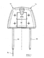
- Fig. 1 shows a front view of the inventive neck rest with no upholstering component.
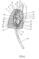
- Fig. 2 shows a section through the neck rest of Fig. 1 taken along the line 2-2.
- Fig. 3 shows a perspective view of the first support portion of the neck rest of Figs. 1 and 2 from the front with the second support portion, which is not shown, in a non-actuated condition.
- Fig. 4 shows a view similar to that of Fig. 3 , but with the second support portion actuated, though not shown in the drawing.
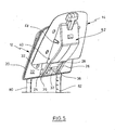
- Fig. 5 shows a perspective view of the neck rest of Figs. 1 and 2 with the second support portion in an actuated condition.
- a neck rest 10 for the back rest of a seat, which is not shown in detail, of an automobile has a first support portion 12 and a second support portion 14.
- An upholstering 16 for the support portion 12 and an upholstering 18 for the support portion 14 are shown in Fig. 2 .
- the upholstering is omitted in the remaining Figures for reasons of representation.
- the support portion 12 will initially be described in more detail below. As ensues from Figs. 2 to 4 it is composed of two plate shaped portions 20 and 22 which are manufactured from a plastic and are interleaved with each other as is specifically apparent from Fig. 2 .
- the two portions 20, 22 define recesses or spaces to receive components yet to be described.
- two parallel cheeks 24, 26 disposed at a spacing from each other are formed at the front of the portion 22.
- the cheeks 24, 26 have pivotally supported therebetween a blocking plate 28 about an axis 30. It is outwardly biased by a spring 32.
- the blocking plate 28 has a blocking shoulder 34 in the upper area.
- the spring 32 biases the blocking plate 28 outwardly.
- the cheeks 24, 26 have a slightly curved guiding slot 36, 38 each which obliquely extends upwards and in which a rod 40 is guided.
- the rod 40 is in the lower area of the slots 36, 38 in Fig. 3 and is in the upper end of the slots 36, 38 in Fig. 4 .
- a recess 42 has supported therein two legged springs 46, 48 side by side on a rod-like bearing 44. Each of them has a first leg 50 and 52 and a second leg 54, 56 at their outer ends. Both of the long legs 50, 52 are provided with a bent-away portion 58 at the end. The legs 54, 56 are fixed in place in a recess 60 of the portions 22 as they engage the recess 60 from above. In contrast, the legs 50, 52 are pivotable. The bent-away portions 58 engage respective holes of the second support portion 14 as can be seen from Fig. 5 . The holes are formed in a hood-like portion 62 at the front of the second support portion 14 on the lateral walls.
- the legged springs 48, 46 are configured such as to bias the second support portion 14 into the upwardly and laterally extracted position as is shown in Fig. 5 and in phantom lines in Fig. 2 .
- the limitation in the position of the second support portion 14 in Figs. 2 and 5 is achieved by the fact that the rod 40 also extends into holes of the hood-like portion 62, which are not shown in detail, and is moved along together with the motion of the second support portion 14, as a result.
- the rod 40 abuts against the upper end of the guiding slots 36, 38.
- An supporting arm 64 is formed to the rear of the second support portion 14. As is shown in the extracted second position of Fig. 5 and in phantom lines in Fig. 2 the free end of the supporting arm 64 engages a horizontal deepening 66 of an extension 98 at the front of the first support portion 12 in the upper region as can be clearly seen in Figs. 3 and 4 . This gives the second support portion 14 a horizontal support on the first support portion 12 when a force acts horizontally onto the second support portion 14 towards the first support portion 12.
- a locking element 68 is pivotally supported horizontally about an axis 70 on the portion 22 of the first support portion 12.
- the locking element 68 is forked at 72 in the upper region and a downwardly projecting extension 74 of the supporting arm 64 engages the forked portion 72 in the first position of the second support portion 14 of Fig. 2 .
- the downwardly facing portion 76 of the locking element abuts against the protrusion of an armature 78 of an electromagnet 90.
- the armature 78 is upwardly biased by a spring 92. This prevents the locking element 68 from pivoting and the second support portion 14 is held in place in the position illustrated in Fig. 2 although the legged springs 48, 46 are biased.
- the first support portion 12 has two neck rest rods 80, 82 which extend downwardly and in parallel at a spacing from each other and can be received in appropriate seats of the back rest of the automobile seat which are not shown.
- the rods 80, 82 are concavely bent as viewed from the bottom.
- the upholstering 18 for the second support portion 14 leaves an opening 84 in the lower region to introduce a tool for pivoting the blocking plate 28 counterclockwise to allow the support portion 14 to be moved back again from the position shown in Fig. 5 to the position shown in Fig. 2 .
- the blocking plate 28 can also be pivoted by hand when the second support portion 14 has been extracted as shown in Fig. 5 . Then, the blocking plate 28 will be freely accessible in its lower region.
- Fig. 1 What can be recognized from Fig. 1 is that the neck rest rods 80, 82 are hollow and the rod 80 has passed therethrough a cable 94 which is led to the electromagnet 90 in order to activate it.
- the source which causes an activation of the electromagnet 90 is not shown.
- the armature 78 of the electromagnet 90 is moved downwards, thereby releasing the locking element 68.
- This enables the supporting arm 64 to pivot the locking element 68 by the extension 74 about the pivot pin 70 in a clockwise sense.
- a releasing element can be used which acts in a way similar to the armature 78, but is actuated by a pulling cable, for example.
Landscapes
- Engineering & Computer Science (AREA)
- Aviation & Aerospace Engineering (AREA)
- Transportation (AREA)
- Mechanical Engineering (AREA)
- Seats For Vehicles (AREA)
- Chairs For Special Purposes, Such As Reclining Chairs (AREA)
Description
- The invention relates to a neck rest for the seat of an automobile according to claim 1.
-
DE 199 61 617 A1 ,DE 199 51 966 A1 orDE 101 42 625 A1 have made known a neck rest which has a supporting member adapted to be advanced to the front on the head of the seat used, and a shock member which actuates it. When there is an impact onto the rear end of the vehicle the shock member is actuated and the supporting member is advanced to the front. The supporting member is mounted on the upholstering carrier via pivoting arms. InDE 199 51 966 A1 , the supporting member forms part of the neck rest upholstering which is composed of two components which are interconnected via joints. The shock member can interact with the supporting member via a pulling cable and be in communication with a releasing element. -
DE 102 08 620 which is the closest prior art describes a neck rest for automobile seats which has a fixed support portion as well as a second support portion for a movable upholstering portion which is movably supported by the first support portion. The second support portion is pivotally supported about a lower horizontal axis on the first support portion and an actuation device is formed by a spring which biases the second support portion. A controllable locking device retains the second support portion in the retracted position on the first support portion. A third support portion is slidably mounted on the second support portion between a lower and an upper position. The third support portion is biased to the upper position by means of a second spring. A controllable second locking device retains the third support portion in the lower position with second locking device being unlocked once the second support portion has reached a predetermined pivoting angle. Further, stop means are provided between the second and third support portions and the first support portion when the second and third support portions have arrived at their extracted positions, to prevent the latter from pivoting back. The structure described last is intended to achieve an optimum absorption of force with the sitting person not undergoing a risk of injury when there is a rear-end shock. - It is the object of the invention to provide a divided neck rest in which simple means take care that if there is an impact against the automobile and an abrupt acceleration the head of the sitting person can be efficiently cushioned against an advanced and raised portion of the neck rest.
- The object is achieved by the features of claim 1.
- Like in the state of the art, the neck rest is also divided into a first and a second support portion in the invention, the first one being mounted on the seat by means of neck rest rods and the second one constituting the movable one. The first support portion mounts a first spring which has at least one leg which is rotationally supported by the second support portion and biases it away from the first support portion. The second support portion has a guiding element which is guided by a guideway of the first support portion in displacing the second support portion from the first position to the second one, and vice versa. A movable blocking element biased by a second spring on the first support portion automatically blocks the second support portion in its second position. A locking element is supported by the first support portion and is adapted to be moved between a locking and an unlocking position. In the locking position, it cooperates with a locking projection of the first support portion to lock the second support portion in the first position. A releasing element movably supported by the first support portion, when in a non-actuated position, blocks the locking element in the locking position. An actuation device acts on the releasing element to unlock the locking element when the releasing element is actuated.
- In the inventive neck rest, the cooperation between the guiding element and guideway and the displacement path of the spring leg of the first spring determine the path of the second support portion during the displacement from the first position to the second one, and vice versa. The leg of the first spring firstly constitutes the actuator for the second support element and secondly forms a mounting for the second support portion in the second position thereof, in which second position supporting means are provided via which an impact onto the upholstering part of the second support portion is cushioned.
- The components required for the displacement of the second support portion and its locking and supporting can be configured as being very simple and be assembled to be very compact. The releasing element can be selectively actuated in an electric or electromagnetic manner or via a pulling cable (Bowden wire), it being left open because of which physical event to release the releasing element. Thus, for example, a sensor responding to an acceleration is imaginable which causes a release of the neck rest once the acceleration rate exceeds a certain amount.
- According to an aspect of the invention, a supporting arm is disposed on that side of the second support portion which faces the first support portion. It interacts with a counter bearing in the upper part of the first support portion. According to an aspect of the invention, the counter bearing can have a deepening which is engaged by the end of the supporting arm.
- According to another aspect of the invention, the guiding element can be formed by a rod or pin or the like which are guided by parallel spaced guiding slots of the first support portion.
- The movable blocking element can be a blocking plate which is biased by the second spring into the blocking position where the rod or the pins interact with a blocking shoulder of the blocking plate when the guiding rod or when the guiding pins are displaced into the second position upon movement of the second support portion.
- According to another aspect of the invention, the supporting arm extending approximately horizontally, on the second support portion, can have a downwardly facing extension which engages an upwardly open locking recess of the locking element which, in turn, is pivotally supported about a horizontal axis on the first support portion. It is understood that the extension and recess can also be interchanged, i.e. the supporting arm can have a recess and the locking element a relative extension which lockingly engages the recess.
- The releasing element maintains the locking element in the locking position and is freed of the locking element during a motion out of the locking position. The releasing element can be linearly movable and be biased by a spring into the locking position. The releasing element can be adapted to be actuated by an electromagnet, for example.
- An embodiment of the invention will now be described in more detail below with reference to the drawings.
-
Fig. 1 shows a front view of the inventive neck rest with no upholstering component. -
Fig. 2 shows a section through the neck rest ofFig. 1 taken along the line 2-2. -
Fig. 3 shows a perspective view of the first support portion of the neck rest ofFigs. 1 and2 from the front with the second support portion, which is not shown, in a non-actuated condition. -
Fig. 4 shows a view similar to that ofFig. 3 , but with the second support portion actuated, though not shown in the drawing. -
Fig. 5 shows a perspective view of the neck rest ofFigs. 1 and2 with the second support portion in an actuated condition. - A neck rest 10 for the back rest of a seat, which is not shown in detail, of an automobile has a
first support portion 12 and asecond support portion 14. Anupholstering 16 for thesupport portion 12 and anupholstering 18 for thesupport portion 14 are shown inFig. 2 . The upholstering is omitted in the remaining Figures for reasons of representation. - The
support portion 12 will initially be described in more detail below. As ensues fromFigs. 2 to 4 it is composed of two plate shapedportions Fig. 2 . The twoportions - As ensues from
Figs. 3 and 4 , twoparallel cheeks portion 22. Thecheeks plate 28 about anaxis 30. It is outwardly biased by aspring 32. Theblocking plate 28 has a blockingshoulder 34 in the upper area. Thespring 32 biases theblocking plate 28 outwardly. Thecheeks slot rod 40 is guided. Therod 40 is in the lower area of theslots Fig. 3 and is in the upper end of theslots Fig. 4 . - A
recess 42 has supported therein two leggedsprings like bearing 44. Each of them has afirst leg second leg long legs away portion 58 at the end. Thelegs recess 60 of theportions 22 as they engage therecess 60 from above. In contrast, thelegs away portions 58 engage respective holes of thesecond support portion 14 as can be seen fromFig. 5 . The holes are formed in a hood-like portion 62 at the front of thesecond support portion 14 on the lateral walls. Only oneportion 58 is shown in a hole of the hood-like portion 62 inFig. 5 . The legged springs 48, 46 are configured such as to bias thesecond support portion 14 into the upwardly and laterally extracted position as is shown inFig. 5 and in phantom lines inFig. 2 . The limitation in the position of thesecond support portion 14 inFigs. 2 and5 is achieved by the fact that therod 40 also extends into holes of the hood-like portion 62, which are not shown in detail, and is moved along together with the motion of thesecond support portion 14, as a result. Thus, in the position shown inFig. 5 for thesecond support portion 14, therod 40 abuts against the upper end of the guidingslots - When the
second support portion 14 is in the second position shown inFig. 5 therod 40 is adjacent to the blockingshoulder 34 of the blockingplate 28. Therefore, a force acting downwardly onto thesecond support portion 14 does not cause a displacement of thesecond support portion 14. - An supporting
arm 64 is formed to the rear of thesecond support portion 14. As is shown in the extracted second position ofFig. 5 and in phantom lines inFig. 2 the free end of the supportingarm 64 engages a horizontal deepening 66 of anextension 98 at the front of thefirst support portion 12 in the upper region as can be clearly seen inFigs. 3 and 4 . This gives the second support portion 14 a horizontal support on thefirst support portion 12 when a force acts horizontally onto thesecond support portion 14 towards thefirst support portion 12. - A locking
element 68 is pivotally supported horizontally about anaxis 70 on theportion 22 of thefirst support portion 12. The lockingelement 68 is forked at 72 in the upper region and a downwardly projectingextension 74 of the supportingarm 64 engages the forkedportion 72 in the first position of thesecond support portion 14 ofFig. 2 . The downwardly facingportion 76 of the locking element abuts against the protrusion of anarmature 78 of anelectromagnet 90. Thearmature 78 is upwardly biased by aspring 92. This prevents the lockingelement 68 from pivoting and thesecond support portion 14 is held in place in the position illustrated inFig. 2 although thelegged springs - It should also be mentioned that the
first support portion 12 has twoneck rest rods Fig. 2 , it can be seen that therods upholstering 18 for thesecond support portion 14 leaves anopening 84 in the lower region to introduce a tool for pivoting the blockingplate 28 counterclockwise to allow thesupport portion 14 to be moved back again from the position shown inFig. 5 to the position shown inFig. 2 . This is because pivoting the blockingplate 28 will release therod 40, thus permitting thesupport portion 14 to be shifted downwardly against the force of thelegged springs plate 28 can also be pivoted by hand when thesecond support portion 14 has been extracted as shown inFig. 5 . Then, the blockingplate 28 will be freely accessible in its lower region. - What can be recognized from
Fig. 1 is that theneck rest rods rod 80 has passed therethrough acable 94 which is led to theelectromagnet 90 in order to activate it. The source which causes an activation of theelectromagnet 90 is not shown. In an activation case, thearmature 78 of theelectromagnet 90 is moved downwards, thereby releasing the lockingelement 68. This enables the supportingarm 64 to pivot the lockingelement 68 by theextension 74 about thepivot pin 70 in a clockwise sense. This unblocks the locking device for thesecond support portion 14 and the second support portion is now pivoted forwards and upwards by means of thelegs legged springs Fig. 5 and is also shown in phantom lines inFig. 2 . Guidance during the displacement of thesupport portion 14 is performed via therod 40 within the guidingslots rod 40 moves in the guidingslots plate 28, which is bent to the front in a slightly convex manner, is pivoted rearwards against thefirst support portion 12 against thespring 32 until therod 40 grips behind the blockingshoulder 34. In this position of thesecond support portion 14, the supportingarm 64 has arrived at theextension 98 and the free end of the supportingarm 64 engages the transversely extending deepening 66 as is depicted in phantom lines inFig. 2 . In this manner, the location of the second support portion with theupholstering 18 is fixed in the extracted second position and forces which act onto thesecond support portion 14 and substantially are horizontal are transferred to the counter bearing 98 from the supportingarm 64, on one hand, and to the guidingslots rod 40, on the other. - In order to displace the
support portion 14 back to the initial position from the second position, an object is introduced through theopening 84 ofFig. 2 by which the blockingplate 28 can be pivoted counterclockwise to cause the blockingshoulder 34 to release therod 40. It will now be possible, by manual downward pressure, to move thesecond support portion 14 back to the position shown inFig. 2 with therod 40 being moved along the guidingslot extension 74 of the supportingarm 64 engages the forkedportion 72 of the lockingelement 68. This locks thesecond support portion 14 on thefirst support portion 12. - Instead of an electromagnet as is shown in
Fig. 2 , a releasing element can be used which acts in a way similar to thearmature 78, but is actuated by a pulling cable, for example.
Claims (13)
- Divided neck rest for a seat of an automobile including the following features:- a plate shaped first support portion (12) which is adapted to be received by sockets in the back rest of the seat through neck rest rods (80, 82),- a plate shaped second support portion (14), with both support portions (12, 14) being provided within an upholstering (16, 18) and having two relative positions that is a first position wherein the second support portion (14) has approximately the same level as the first support portion (12) and a second position wherein the second support portion (14) is elevated and removed in the direction of the automobile relative to the first support portion (12),- a first spring means (46, 48) supported by the first support portion (12) and having at least one leg (50, 52) a portion of the leg (58) being rotatably connected to the second support portion (14) and biasing the second support portion (14) into the second position- a guiding element (40) at the second support portion (14) which is guided by guiding means (36,38) of the first support portion (12) during the displacement of the second support portion (14) into the second and the first positions- a movable blocking element (28) biased by a second spring means (32) on the first support portion which automatically blocks the second support portion (14) in the second position,- a locking element (68) which is movably supported by the first support portion and adapted to be moved between a locking and a releasing position, the locking element (68) cooperating with a locking projection (74) of the second support portion (14) facing the first support portion (12) in the locking position thereof in order to lock the second support portion (14) in the first position,- a releasing element (78) movably supported by the first support portion (12) which in non-actuated position locks the locking element in the locking position,- actuation means (90) for the releasing element and- supporting means (64, 98) between the first and the second support portions (12, 14) in the second position of the second support portion (14) for the transfer of shock forces from the second support portion (14) to the first support portion (12).
- The neck rest of claim 1, wherein a supporting arm (64) on the second support portion (12) forms a support means in that it co-acts with a counter bearing (98) at the upper portion of the first support portion (12).
- The neck rest of claim 2, wherein the counter bearing (98) has a transversely extending deepening (66) which is engaged by the free end of the supporting arm (64).
- The neck rest of claim 1, wherein the guiding element is formed by a rod (40) or pins which are guided by two parallel spaced guiding slots (36, 38) of the first support portion (12).
- The neck rest of claim 4, wherein a blocking plate (28) is biased into the blocking position by the second spring means (32), the blocking plate (28) being pivotally supported by the first support portion (12), and the rod (40) or the pins engage a blocking shoulder (34) of the blocking plate (28) when the guiding rod (40) or the guiding pins are displaced upon movement of the second support portion (14) into the second position.
- The neck rest of claim 2, wherein the approximately horizontally extending supporting arm (64) has an downwardly facing extension (74) which engages a locking recess of the locking element (68) which in turn is pivotally supported by the first support portion (12) for rotation about a horizontal axis.
- The neck rest of claim 6, wherein the releasing element (78) is longitudinally movable between a releasing and a locking position in the first support portion (12) and in the locking position locks the locking element (68) against a pivoting in the releasing position.
- The neck rest of claim 7, wherein the releasing element (78) is biased into a locking position by third spring means (92).
- The neck rest of claim 7 or 8, wherein the releasing element (78) is actuated by an electromagnet (90).
- The neck rest of claim 1, wherein the neck rest rods (80, 82) are bent each in a vertical plane towards the second support portion (14).
- The neck rest of claim 1, wherein the first support portion (12) on the side facing the second support portion (14) has two parallel spaced extensions (24, 26) each including a guiding slot (36, 38), the extensions (24, 26) supporting the platelike blocking element (28) for rotation.
- The neck rest of claim 1, wherein two first spring means (46, 48) are provided and formed as coil springs with two legs (50, 54; 52, 56) at the ends thereof, wherein the first legs (50, 52) engage the second support portion (14) and the second legs (54,56) engage the first support portion (12).
- The neck rest of claim 1, wherein the first support portion (12) includes two plastic plate portions (20, 22) lying against each other with one (20) supporting the upholstering (16) and the other (22) the parts retained on the first support portion (12).
Applications Claiming Priority (2)
| Application Number | Priority Date | Filing Date | Title |
|---|---|---|---|
| DE10335268 | 2003-08-01 | ||
| DE10335268A DE10335268B3 (en) | 2003-08-01 | 2003-08-01 | Headrest for automobile passenger seat, has fixed plate-shaped carrier component and relatively displaced plate-shaped carrier element used for protecting neck of passenger upon rear collision |
Publications (3)
| Publication Number | Publication Date |
|---|---|
| EP1502809A2 EP1502809A2 (en) | 2005-02-02 |
| EP1502809A3 EP1502809A3 (en) | 2008-05-14 |
| EP1502809B1 true EP1502809B1 (en) | 2009-05-27 |
Family
ID=33483098
Family Applications (1)
| Application Number | Title | Priority Date | Filing Date |
|---|---|---|---|
| EP04015049A Expired - Lifetime EP1502809B1 (en) | 2003-08-01 | 2004-06-26 | A neck rest for the seat of an automobile |
Country Status (5)
| Country | Link |
|---|---|
| US (1) | US7048336B2 (en) |
| EP (1) | EP1502809B1 (en) |
| CA (1) | CA2473484C (en) |
| DE (2) | DE10335268B3 (en) |
| MX (1) | MXPA04007439A (en) |
Cited By (1)
| Publication number | Priority date | Publication date | Assignee | Title |
|---|---|---|---|---|
| US7862119B2 (en) | 2005-04-08 | 2011-01-04 | Alfmeier Prazision Ag Baugruppen Und Systemlosungen | Vehicle seat with lordosis support |
Families Citing this family (30)
| Publication number | Priority date | Publication date | Assignee | Title |
|---|---|---|---|---|
| WO2004062963A1 (en) | 2003-01-10 | 2004-07-29 | Alfmeier Präzision AG | Fastening device for the headrest of a vehicle seat |
| DE502005000317D1 (en) | 2004-03-19 | 2007-03-08 | Alfmeier Praez Ag | Vehicle seat with a swivel-mounted headrest |
| US7407231B2 (en) | 2004-05-14 | 2008-08-05 | Alfmeier Prazision Ag Baugruppen Und Systemlosungen | Vehicle seat with a headrest and headrest adjustment assembly |
| DE102005009128B3 (en) * | 2005-03-01 | 2006-06-22 | Keiper Gmbh & Co.Kg | Method for assembly of crash activated headrest in vehicle seating involves headrest which is assembled to vehicle seating along with rear and front bearing shell which are equipped with sub-assembly |
| CA2595054A1 (en) * | 2006-07-06 | 2008-01-06 | Les Aciers Robond Inc. | Adjustable headrest assembly |
| US8123292B2 (en) | 2006-08-31 | 2012-02-28 | Toyota Boshoku Kabushiki Kaisha | Vehicle seat |
| JP4872544B2 (en) * | 2006-08-31 | 2012-02-08 | トヨタ紡織株式会社 | Vehicle seat |
| GB2482807B8 (en) * | 2006-12-12 | 2012-04-04 | Wonderland Nursery Goods | Head rest and harness adjustment for child car seat |
| DE102006061302B3 (en) * | 2006-12-22 | 2008-04-30 | Keiper Gmbh & Co.Kg | Headrest for vehicle seat has the cushion mounted on a sprung mounting to move into a forward crash support position in a collision |
| DE102007005737B4 (en) | 2007-01-31 | 2010-06-10 | Alfmeier Präzision AG Baugruppen und Systemlösungen | Headrest system for a vehicle seat |
| JP5191138B2 (en) * | 2007-02-14 | 2013-04-24 | 株式会社イノアックコーポレーション | Headrest |
| US7845721B2 (en) * | 2007-02-14 | 2010-12-07 | Inoac Corporation | Headrest |
| US8037126B2 (en) * | 2007-03-12 | 2011-10-11 | Citrix Systems, Inc. | Systems and methods of dynamically checking freshness of cached objects based on link status |
| US7992933B2 (en) * | 2007-06-21 | 2011-08-09 | Lear Corporation | Integrated vehicle seat with active head restraint system |
| DE102007048151B3 (en) * | 2007-09-04 | 2009-01-22 | Lear Corporation, Southfield | Seat e.g. front seat, for e.g. car, has locking mechanism with spindle having eccentric drive that works together with one ratchet such that release device rotates spindle and moves ratchet from connection with other ratchet |
| US7871129B2 (en) * | 2007-12-05 | 2011-01-18 | Lear Corporation | Seat assembly having an adjustable head restraint assembly |
| US8100472B2 (en) * | 2008-03-17 | 2012-01-24 | Lear Corporation | Vehicle active head restraint system with a locking linkage |
| ES2344496B1 (en) | 2008-07-24 | 2011-08-17 | Batz, S. Coop. | "REPLACEMENT FOR SEATS OF MOTOR VEHICLES". |
| DE102008045021B3 (en) * | 2008-08-29 | 2009-10-29 | Itw Automotive Products Gmbh | Headrest for vehicle, has impact plate with guide guiding pivoting movement of impact plate around axis such that plate is maintained in angular position against bracket during movement of plate from rest position into accident position |
| DE102010003109B9 (en) * | 2009-04-22 | 2012-12-13 | Lear Corporation | Seat arrangement with movable headrest |
| DE102009020117B4 (en) * | 2009-05-06 | 2013-11-14 | Lear Corp. | Seat assembly and adjustable head restraint assembly |
| DE102010002525B9 (en) * | 2009-05-28 | 2012-12-13 | Lear Corp. | Seat assembly with a movable headrest assembly |
| DE102009045833A1 (en) * | 2009-10-20 | 2011-05-26 | Lear Corp., Southfield | Seat device with an adjustable headrest device |
| DE102009046660B4 (en) * | 2009-11-12 | 2011-11-10 | Lear Corporation | Seat arrangement with a movable headrest |
| US8657378B2 (en) | 2010-10-04 | 2014-02-25 | Lear Corporation | Seat assembly having an adjustable head restraint assembly |
| DE102011005590B4 (en) | 2011-03-16 | 2013-05-16 | Lear Corporation | Seat assembly with a movable headrest assembly |
| DE102011006243B4 (en) | 2011-03-28 | 2016-11-17 | Lear Corporation | Height-adjustable headrest for vehicle seats |
| EP2753498B1 (en) | 2011-09-07 | 2019-08-28 | Adient Luxembourg Holding S.à r.l. | Height-adjustable head restraint for a vehicle seat and vehicle seat with a height-adjustable head restraint |
| JP6107459B2 (en) * | 2013-06-18 | 2017-04-05 | トヨタ紡織株式会社 | Vehicle seat |
| DE102013224194A1 (en) | 2013-11-27 | 2015-05-28 | Johnson Controls Gmbh | vehicle seat |
Family Cites Families (23)
| Publication number | Priority date | Publication date | Assignee | Title |
|---|---|---|---|---|
| GB2037154A (en) | 1978-10-31 | 1980-07-09 | Cox Ltd | Head restraints for vehicle seats |
| US4278291A (en) * | 1979-01-23 | 1981-07-14 | Kozo Asai | Adjustable headrest |
| US4278391A (en) | 1979-03-02 | 1981-07-14 | Dagenais Joseph E | Protection means for tracks in a track-laying vehicle |
| DE3347255C2 (en) | 1983-12-28 | 1986-08-14 | E M D A Fabrik elektro-medizinischer und dentaler Apparate Georg Hartmann GmbH & Co KG, 6000 Frankfurt | Dental patient chair with headrest |
| DE3404612A1 (en) | 1984-02-09 | 1985-08-14 | C. Rob. Hammerstein Gmbh, 5650 Solingen | HEADREST OF A VEHICLE SEAT WITH TWO CARRIAGE BRACKETS ATTACHED TO THE SEATREST |
| DE3900495A1 (en) | 1989-01-10 | 1990-07-26 | Bayerische Motoren Werke Ag | Head restraint for a motor-vehicle seat |
| DE29504287U1 (en) | 1995-03-13 | 1995-05-11 | Bonke, Christoph, Dr., 83126 Flintsbach | Individually adjustable headrest for seats with a backrest |
| IT1280437B1 (en) * | 1995-07-19 | 1998-01-20 | Lear Seating Italia Spa | VEHICLE SEAT |
| DE29603991U1 (en) | 1996-03-04 | 1996-07-04 | Trw Occupant Restraint Systems Gmbh, 73551 Alfdorf | Vehicle seat |
| DE19707998B4 (en) | 1997-02-27 | 2007-04-05 | Inova Gmbh Technische Entwicklungen | Automotive seat |
| NL1008342C2 (en) | 1998-02-18 | 1999-08-19 | Tno | Vehicle seat with a headrest and a vehicle with such a seat. |
| DE29808982U1 (en) | 1998-05-18 | 1998-09-17 | TRW Occupant Restraint Systems GmbH & Co. KG, 73553 Alfdorf | Headrest with gas bag module |
| US5904405A (en) | 1998-08-07 | 1999-05-18 | Wu; Frank | Pillow structure for chairs |
| US6213548B1 (en) | 1999-08-12 | 2001-04-10 | Trw Inc. | Head restraint apparatus |
| DE19951966B4 (en) * | 1999-10-28 | 2006-11-02 | Bayerische Motoren Werke Ag | Vehicle seat with a provided on the backrest or on the vehicle body headrest |
| DE19961617C2 (en) * | 1999-12-21 | 2003-01-30 | Daimler Chrysler Ag | Backrest for a vehicle seat |
| DE10005196B4 (en) | 2000-02-05 | 2006-07-27 | Bayerische Motoren Werke Ag | Headrest on a vehicle seat |
| GB0014699D0 (en) | 2000-06-15 | 2000-08-09 | Autoliv Dev | Improvements in or relating to a head-rest |
| DE10030549B4 (en) | 2000-06-21 | 2011-01-27 | Lear Corporation Gmbh & Co. Kg | vehicle seat |
| DE10047406A1 (en) * | 2000-09-26 | 2002-04-11 | Daimler Chrysler Ag | headrest |
| DE10142625C2 (en) * | 2001-08-31 | 2003-12-11 | Itw Automotive Prod Gmbh & Co | Headrest for automobile seats |
| DE10208620C1 (en) * | 2002-02-27 | 2003-07-24 | Itw Automotive Prod Gmbh & Co | Headrest for automobile passenger seat has 2 adjustable components deployed for cushioning head and neck in rear impact situation |
| DE10224060C1 (en) * | 2002-05-31 | 2003-07-24 | Daimler Chrysler Ag | Headrest for automobile passenger seat adjustable between different working positions and returned to initial position in rear impact situation |
-
2003
- 2003-08-01 DE DE10335268A patent/DE10335268B3/en not_active Expired - Fee Related
-
2004
- 2004-06-26 EP EP04015049A patent/EP1502809B1/en not_active Expired - Lifetime
- 2004-06-26 DE DE602004021216T patent/DE602004021216D1/en not_active Expired - Fee Related
- 2004-07-12 CA CA002473484A patent/CA2473484C/en not_active Expired - Fee Related
- 2004-07-13 US US10/889,033 patent/US7048336B2/en not_active Expired - Fee Related
- 2004-07-30 MX MXPA04007439A patent/MXPA04007439A/en active IP Right Grant
Cited By (1)
| Publication number | Priority date | Publication date | Assignee | Title |
|---|---|---|---|---|
| US7862119B2 (en) | 2005-04-08 | 2011-01-04 | Alfmeier Prazision Ag Baugruppen Und Systemlosungen | Vehicle seat with lordosis support |
Also Published As
| Publication number | Publication date |
|---|---|
| DE10335268B3 (en) | 2004-12-23 |
| MXPA04007439A (en) | 2005-02-03 |
| EP1502809A2 (en) | 2005-02-02 |
| EP1502809A3 (en) | 2008-05-14 |
| DE602004021216D1 (en) | 2009-07-09 |
| CA2473484C (en) | 2008-03-25 |
| US7048336B2 (en) | 2006-05-23 |
| CA2473484A1 (en) | 2005-02-01 |
| US20050046262A1 (en) | 2005-03-03 |
Similar Documents
| Publication | Publication Date | Title |
|---|---|---|
| CA2473484C (en) | A neck rest for the seat of an automobile | |
| EP1584514B1 (en) | A neck rest for seats of automobiles | |
| US7111901B2 (en) | Headrest for automotive vehicle seats | |
| US8066330B2 (en) | Motor-vehicle headrest | |
| KR101418889B1 (en) | Headrest | |
| US20030057748A1 (en) | Head restraint for a vehicle seat | |
| US6742846B1 (en) | Modified head restraint assembly for motor vehicle seats | |
| US20110291456A1 (en) | Headrest for motor-vehicle seat | |
| JP5663664B2 (en) | Latch device for headrest | |
| CN107640072A (en) | Seat-assembly with adjustable head restraint assembly | |
| US20060267384A1 (en) | Head rest arrangement for a motor vehicle seat | |
| CN102205802B (en) | Seat slide lock | |
| US7669932B1 (en) | Headrest | |
| KR101081926B1 (en) | Headrest Moving Device | |
| GB2424827A (en) | Movable vehicle head restraint for improved rear vision | |
| JP2004526626A (en) | Motor seat with motor | |
| KR101549969B1 (en) | Apparatus for locking arm rest in vehicle | |
| CN108973784B (en) | Vehicle seat and seat operating unit | |
| EP1475267A2 (en) | Child safety seat | |
| JP4313058B2 (en) | Walk-in lock mechanism with memory in seat track slide device | |
| KR100979273B1 (en) | Head rest | |
| CN117962723A (en) | Four-way adjustable seat headrest and car | |
| JP5601907B2 (en) | Seat unlock lever device | |
| KR100503454B1 (en) | Locking device for seat-track of vehicles | |
| EP3213959B1 (en) | Headrest retraction member, and vehicle seat |
Legal Events
| Date | Code | Title | Description |
|---|---|---|---|
| PUAI | Public reference made under article 153(3) epc to a published international application that has entered the european phase |
Free format text: ORIGINAL CODE: 0009012 |
|
| 17P | Request for examination filed |
Effective date: 20040709 |
|
| AK | Designated contracting states |
Kind code of ref document: A2 Designated state(s): AT BE BG CH CY CZ DE DK EE ES FI FR GB GR HU IE IT LI LU MC NL PL PT RO SE SI SK TR |
|
| AX | Request for extension of the european patent |
Extension state: AL HR LT LV MK |
|
| PUAL | Search report despatched |
Free format text: ORIGINAL CODE: 0009013 |
|
| AK | Designated contracting states |
Kind code of ref document: A3 Designated state(s): AT BE BG CH CY CZ DE DK EE ES FI FR GB GR HU IE IT LI LU MC NL PL PT RO SE SI SK TR |
|
| AX | Request for extension of the european patent |
Extension state: AL HR LT LV MK |
|
| GRAP | Despatch of communication of intention to grant a patent |
Free format text: ORIGINAL CODE: EPIDOSNIGR1 |
|
| AKX | Designation fees paid |
Designated state(s): DE ES FR GB IT SE |
|
| GRAS | Grant fee paid |
Free format text: ORIGINAL CODE: EPIDOSNIGR3 |
|
| GRAA | (expected) grant |
Free format text: ORIGINAL CODE: 0009210 |
|
| AK | Designated contracting states |
Kind code of ref document: B1 Designated state(s): DE ES FR GB IT SE |
|
| REG | Reference to a national code |
Ref country code: GB Ref legal event code: FG4D |
|
| REF | Corresponds to: |
Ref document number: 602004021216 Country of ref document: DE Date of ref document: 20090709 Kind code of ref document: P |
|
| RAP2 | Party data changed (patent owner data changed or rights of a patent transferred) |
Owner name: ITW AUTOMOTIVE PRODUCTS GMBH & CO. KG |
|
| PG25 | Lapsed in a contracting state [announced via postgrant information from national office to epo] |
Ref country code: SE Free format text: LAPSE BECAUSE OF FAILURE TO SUBMIT A TRANSLATION OF THE DESCRIPTION OR TO PAY THE FEE WITHIN THE PRESCRIBED TIME-LIMIT Effective date: 20090827 |
|
| PG25 | Lapsed in a contracting state [announced via postgrant information from national office to epo] |
Ref country code: ES Free format text: LAPSE BECAUSE OF FAILURE TO SUBMIT A TRANSLATION OF THE DESCRIPTION OR TO PAY THE FEE WITHIN THE PRESCRIBED TIME-LIMIT Effective date: 20090907 |
|
| PLBE | No opposition filed within time limit |
Free format text: ORIGINAL CODE: 0009261 |
|
| STAA | Information on the status of an ep patent application or granted ep patent |
Free format text: STATUS: NO OPPOSITION FILED WITHIN TIME LIMIT |
|
| GBPC | Gb: european patent ceased through non-payment of renewal fee |
Effective date: 20090827 |
|
| 26N | No opposition filed |
Effective date: 20100302 |
|
| PG25 | Lapsed in a contracting state [announced via postgrant information from national office to epo] |
Ref country code: DE Free format text: LAPSE BECAUSE OF NON-PAYMENT OF DUE FEES Effective date: 20100101 |
|
| PG25 | Lapsed in a contracting state [announced via postgrant information from national office to epo] |
Ref country code: FR Free format text: LAPSE BECAUSE OF NON-PAYMENT OF DUE FEES Effective date: 20090727 |
|
| REG | Reference to a national code |
Ref country code: FR Ref legal event code: ST Effective date: 20100930 |
|
| PG25 | Lapsed in a contracting state [announced via postgrant information from national office to epo] |
Ref country code: GB Free format text: LAPSE BECAUSE OF NON-PAYMENT OF DUE FEES Effective date: 20090827 |
|
| PG25 | Lapsed in a contracting state [announced via postgrant information from national office to epo] |
Ref country code: IT Free format text: LAPSE BECAUSE OF FAILURE TO SUBMIT A TRANSLATION OF THE DESCRIPTION OR TO PAY THE FEE WITHIN THE PRESCRIBED TIME-LIMIT Effective date: 20090527 |