EP1502784B2 - Electric heating device - Google Patents
Electric heating device Download PDFInfo
- Publication number
- EP1502784B2 EP1502784B2 EP03291944A EP03291944A EP1502784B2 EP 1502784 B2 EP1502784 B2 EP 1502784B2 EP 03291944 A EP03291944 A EP 03291944A EP 03291944 A EP03291944 A EP 03291944A EP 1502784 B2 EP1502784 B2 EP 1502784B2
- Authority
- EP
- European Patent Office
- Prior art keywords
- previous
- component
- current
- partial unit
- heat
- Prior art date
- Legal status (The legal status is an assumption and is not a legal conclusion. Google has not performed a legal analysis and makes no representation as to the accuracy of the status listed.)
- Expired - Fee Related
Links
Images


Classifications
-
- B—PERFORMING OPERATIONS; TRANSPORTING
- B60—VEHICLES IN GENERAL
- B60H—ARRANGEMENTS OF HEATING, COOLING, VENTILATING OR OTHER AIR-TREATING DEVICES SPECIALLY ADAPTED FOR PASSENGER OR GOODS SPACES OF VEHICLES
- B60H1/00—Heating, cooling or ventilating [HVAC] devices
- B60H1/22—Heating, cooling or ventilating [HVAC] devices the heat being derived otherwise than from the propulsion plant
- B60H1/2215—Heating, cooling or ventilating [HVAC] devices the heat being derived otherwise than from the propulsion plant the heat being derived from electric heaters
- B60H1/2225—Heating, cooling or ventilating [HVAC] devices the heat being derived otherwise than from the propulsion plant the heat being derived from electric heaters arrangements of electric heaters for heating air
-
- F—MECHANICAL ENGINEERING; LIGHTING; HEATING; WEAPONS; BLASTING
- F24—HEATING; RANGES; VENTILATING
- F24H—FLUID HEATERS, e.g. WATER OR AIR HEATERS, HAVING HEAT-GENERATING MEANS, e.g. HEAT PUMPS, IN GENERAL
- F24H3/00—Air heaters
- F24H3/02—Air heaters with forced circulation
- F24H3/04—Air heaters with forced circulation the air being in direct contact with the heating medium, e.g. electric heating element
- F24H3/0405—Air heaters with forced circulation the air being in direct contact with the heating medium, e.g. electric heating element using electric energy supply, e.g. the heating medium being a resistive element; Heating by direct contact, i.e. with resistive elements, electrodes and fins being bonded together without additional element in-between
- F24H3/0429—For vehicles
- F24H3/0441—Interfaces between the electrodes of a resistive heating element and the power supply means
- F24H3/0447—Forms of the electrode terminals, e.g. tongues or clips
-
- B—PERFORMING OPERATIONS; TRANSPORTING
- B60—VEHICLES IN GENERAL
- B60H—ARRANGEMENTS OF HEATING, COOLING, VENTILATING OR OTHER AIR-TREATING DEVICES SPECIALLY ADAPTED FOR PASSENGER OR GOODS SPACES OF VEHICLES
- B60H1/00—Heating, cooling or ventilating [HVAC] devices
- B60H1/22—Heating, cooling or ventilating [HVAC] devices the heat being derived otherwise than from the propulsion plant
- B60H2001/2268—Constructional features
- B60H2001/2278—Connectors, water supply, housing, mounting brackets
Definitions
- the present invention relates to a device for exchanging heat, and more particularly to an electric heater.
- Such devices for exchanging heat are used, for example, for heating air in motor vehicles.
- Such an electric heating device for heating the air conducted into the interior of a vehicle has electrical heating elements and heat conductors to which the air to be heated flows.
- electrical heating elements Preferably, but not exclusively, ceramic heating elements having positive temperature coefficients (PTC heating elements) are used as electrical heating elements.
- PTC heating elements positive temperature coefficients
- other heating elements such as resistance heating elements, plasma heating elements and / or the like may also be used.
- the heat emitted by the heating elements is dissipated by heat conduction, which are designed for example in the form of corrugated fins or fins, discharged to the air to be heated.
- the heating elements are preferably held in a receiving device.
- Object of the present invention is to provide a device for exchanging heat, which is designed so that both the connection, the electrical heating elements with the voltage source, the control and / or regulation of the heating elements and the heat conduction between the PTC element and the air can be provided in a simple manner.
- the inventive device for exchanging heat has a plurality of heat exchanger assemblies, said heat exchanger modules have at least a first component, which is connected to an electrical power source, and whose temperature changes in dependence of a current flowing through the component.
- at least one second component is provided, with at least one first and at least one second subunit, which are connected to the poles of a current source in order to generate a current flow through the first component.
- at least one connecting device is provided which is in mechanically detachable and electrical connection with at least one first or at least one second subunit of at least one heat exchanger subassembly.
- the connecting device is preferred with several, more preferably with all, first or second subunits of the individual heat exchanger assemblies In mechanically detachable and electrical connection.
- At least one subunit has a first connecting member and the connecting device has a plurality of second connecting members, wherein at least one first and / or one second connecting member has an element which engages at least in a second and / or a first connecting member.
- a control and / or regulating device is further provided, which regulates the flow of current through at least one first component essentially independent of the current flow through at least one further first component.
- a connecting link is understood to mean a device which is suitable for entering into a mechanical, not necessarily permanent, connection with a further connecting link.
- Such connecting members according to the invention have mutually hooking or interlocking elements.
- a connection device is understood to be a device which is suitable for producing or effecting a particularly electrical connection between individual, but preferably not exclusively, several components and a current source.
- the connecting device extends at a predetermined angle ⁇ with respect to the longitudinal direction of the subunits.
- the subunits may be, for example, contact plates that have a predetermined length and one opposite to this Length significantly reduced width and significantly reduced thickness.
- the subunits lie in a preferred embodiment substantially parallel to each other. Between the subunits each of the first components are arranged.
- the predetermined angle ⁇ is between 60 ° and 120 °, preferably between 75 ° and 105 ° and particularly preferably at about 90 °.
- a multiplicity of heat transfer devices designed as turbulence devices are arranged between the first component and at least one subunit of the second component, which convey heat exchange with a circulating medium.
- the medium flowing around is preferably air to be heated.
- the turbulence device can be corrugated ribs with or without fins and the like.
- the first component has at least one heating element with a positive temperature coefficient (PTC element).
- PTC element positive temperature coefficient
- the plurality of first subunits and the plurality of second subunits are alternating, i. H. arranged alternately.
- This is to be understood as meaning that in each case a first subunit is followed by a second subunit, and on this again a first subunit, etc.
- the different subunits are connected to the poles of a voltage source, so that in each case a current flow can occur between a predetermined number of subunits ,
- At least the first and / or the second connecting member has a Einschububworts noticed which engages in the element of the second and / or the first link. It may be a projection or a tab, which are inserted into the element. This tab, in the preferred embodiment, may have rounded corners or edges, or sloping corners or edges that cause the connector to be more easily inserted into an element (insertion aid).
- the element has at least one flexible contact element.
- a flexible contact element is understood to be an element which can be elastically bent or displaced from its starting position.
- the flexible contact element will exert a force on the second connecting member in the direction of its initial position.
- At least one connecting element or an element has a recess. This may be, for example, a slot or the like.
- the connecting device has at least one opening.
- This opening can have any geometric cross sections, such as circular, polygonal or rectangular cross-sections.
- the invention has a cross section whose longer side exceeds the shorter side.
- the connecting device has at least one recess.
- the recess may also have any geometric cross sections of the type mentioned above.
- At least one first subunit or at least one second subunit has an insulating device with which the first or the second subunit is electrically insulated from the connecting device.
- This may preferably be a non-electrically conductive plastic or the like.
- the first or the second subunit is surrounded by the insulating device such that an electrical contact with the connecting device is substantially prevented.
- the plastic can be molded onto the relevant subunit.
- the connecting device has a power supply device.
- the connection between the connection device and the power supply device is selected from a group of non-positive, positive and cohesive connections, which includes, for example, screwing, welding, gluing and the like.
- At least one first or at least one second subunit is connected to a control and / or regulating device.
- the current flowing through the heating device can be controlled and / or regulated with the device.
- the device is arranged in a receiving device.
- this receiving device for example, have frame elements that serve to stabilize the device before.
- the receiving device consists at least partially of an electrically insulating material, in particular of an electrically insulating plastic, composite plastic or a ceramic.
- means are provided which mechanically clamp the first component and the devices lying between a subunit of the second component and the first component.
- clamping devices such as a spring, which cause a tension between individual or all components.
- current-conducting components are provided, between which the first component is arranged.
- these may be contact plates which themselves are not connected directly to a current or voltage source and between which the first component is sandwiched. It is also possible to arrange the PTC element or elements between a current component component and a subunit of the second component.
- these current-conducting components serve to enable the flow of current between the subunits and through the PTC elements, on the other hand they are also suitable for the transmission of the heat generated by the PTC elements.
- a second connecting device is provided which is in mechanically detachable and electrical connection with at least one second subunit of at least one heat exchanger subassembly.
- This second connecting device is preferably in a mechanically detachable and electrical connection with several, particularly preferred, with a predetermined number of second subunits of the heat exchanger modules.
- control and / or regulating means which regulate the current flowing through the heating elements, selected from a group of devices comprising semiconductor components such as but not limited to transistors, power transistors, mechanical and / or electronic switches and the like ,
- the electrical connection between the printed circuit board (in particular the ceramic substrate) and the contact surfaces (32) of the connecting members and / or other elements to be connected by means of the wiring of at least one flexible electrically conductive wire, in particular but not exclusively wire bonding.
- At least one current connection device is provided, which is designed to be rotatable relative to the device.
- the power connection device is preferably articulated in contact with the power supply device and can thus be rotated relative to this.
- the invention is further directed to a device for exchanging heat, in particular an air conditioning system for a motor vehicle, in which at least one device for exchanging heat of the type described above is arranged in at least one flow channel of this air conditioning system.
- a device according to the invention for the exchange of heat is shown in an exploded view.
- the reference numeral 1 refers to a heating block, inter alia, corrugated fins 8, contact plates 7 and 9, or Stromleitkomponenten and arranged between the contact plates PTC elements.
- the contact plates 7 lugs or connecting members 3, which ultimately serve to connect to an electrical power source.
- the contact sheets or Stromleitkomponenten 9, however, have no such tabs.
- the reference numeral 15 refers to a frame means in which the heating block is arranged.
- the frame means is made of non-electrically conductive material.
- the reference numeral 2 denotes a connecting device which can be assembled together with the heating block 1 during assembly.
- this reference numeral 5 refers to a second link, which engages with the first link 3 in one another.
- the reference numeral 13 denotes a holding element, with which the connecting device 2 and thus the complete device can be screwed for example to the body of a vehicle.
- the reference numeral 17 refers to an outer frame member, which serves the further stiffening.
- Fig. 2 is a detail view Fig. 1 shown.
- the reference numeral 5 again refers to the second connecting member attached to the connecting device.
- the reference numeral 5a denotes a chamfered area, which facilitates insertion of the member into the first link 3.
- the first link 3 has a flexible portion 3a which is suitable for clamping the second link 5.
- two flexible members 3a and 3b could be provided, as well as other plug-in mechanisms known from the prior art.
- the reference numeral 19 denotes a recess into which the flexible portion 3a can be inserted.
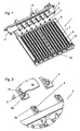
- Fig. 3 is the device for exchanging heat Fig. 1 shown in assembled condition.
- Fig. 4 shows a partial view Fig. 3 , It can be seen in which way the section 3a is inserted into the recess 19 and how, on the other hand, the second connecting member 5 engages or is inserted into the first connecting member 3.
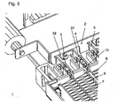
- Fig. 5 the device according to the invention for the exchange of heat is shown in sections, wherein the contacts of the first and second subunits of the second component are shown. Both the first subunit 7 and the second subunit 6 have connecting links 3 and 4. Second connecting links 5 engage in the first connecting links 3, second connecting links 31 engage in the connecting links 4. These second connecting links 31 open into contact surfaces 32.
- Fig. 6 the device according to the invention for the exchange of heat is shown.
- reference numerals 3 and 5 again denote the individual links.
- the links have the same orientation and are preferably substantially in the same plane.
- Reference numeral 33 refers to a circuit board on which elements for regulating the power supply are attached to the individual subunits, such as transistors, in particular power transistors, switching devices, resistors and the like.
- Reference numerals 16 and 36 refer to power supply means which serve to supply power to the heat exchanging apparatus.
- the power connection devices 41 and 42 shown in the upper figure are connected to the opposite poles of a power source.
- the individual heat exchanger modules can be controlled and / or regulated separately from each other.
- Fig. 6 8 such heat exchanger assemblies are shown. However, it is also possible to provide several or fewer such assemblies.
- the connecting device 2 is connected to the ground (-) and the individual connecting links 31 to the positive pole.
- the individual switching devices or the circuit board can be connected to the positive or the negative pole of the voltage source.
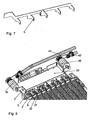
- connection device 2 of the device according to the invention for exchanging heat of this embodiment is shown.
- the reference numeral 5 refers to the connecting member, which also has slopes, which facilitate insertion into the connecting member 3.
- Fig. 8 shows the inventive device for the exchange of heat Fig. 6 in a perspective view.
- the connection between the power supply means 16 and 36 and the guide means 41 and 42 may be articulated so that the means 41 and 42 can be rotated with respect to the power supply means 16 and 36.
Description
Die vorliegende Erfindung betrifft eine Vorrichtung zum Austausch von Wärme und insbesondere eine elektrische Heizvorrichtung. Derartige Vorrichtungen zum Austausch von Wärme werden beispielsweise zum Beheizen von Luft in Kraftfahrzeugen verwendet.The present invention relates to a device for exchanging heat, and more particularly to an electric heater. Such devices for exchanging heat are used, for example, for heating air in motor vehicles.
Die vorliegende Erfindung wird nachfolgend am Beispiel einer elektrischen Heizvorrichtung zum Beheizen des Innenraums eines Kraftfahrzeuges beschrieben. Es sei jedoch darauf hingewiesen, dass die erfindungsgemäße Vorrichtung auch für andere Anwendungszwecke geeignet ist.The present invention will be described below using the example of an electric heater for heating the interior of a motor vehicle. It should be noted, however, that the device according to the invention is also suitable for other applications.
Eine solche elektrische Heizvorrichtung zum Beheizen der in den Innenraum eines Fahrzeugs geleiteten Luft weist elektrische Heizelemente und Wärmeleiter auf, an welchen die zu erwärmende Luft vorbeiströmt. Als elektrische Heizelemente werden vorzugsweise, aber nicht ausschließlich, keramische Heizelemente mit positiven Temperaturkoeffizienten (PTC-Heizelemente) verwendet. Es können jedoch auch andere Heizelemente, wie zum Beispiel Widerstands-Heizelemente, Plasma-Heizelemente und/oder dergleichen Anwendung finden.Such an electric heating device for heating the air conducted into the interior of a vehicle has electrical heating elements and heat conductors to which the air to be heated flows. Preferably, but not exclusively, ceramic heating elements having positive temperature coefficients (PTC heating elements) are used as electrical heating elements. However, other heating elements such as resistance heating elements, plasma heating elements and / or the like may also be used.
Die von den Heizelementen abgegebene Wärme wird mittels Wärmeleitung, welche beispielsweise in Form von Wellrippen oder Lamellen ausgeführt sind, an die zu erwärmende Luft abgeführt.The heat emitted by the heating elements is dissipated by heat conduction, which are designed for example in the form of corrugated fins or fins, discharged to the air to be heated.
Ferner ist es bekannt, die elektrische Verbindung der PTC-Elemente mit der jeweiligen Stromquelle durch Verwendung von Kontaktblechen zu erreichen. Die Heizelemente werden vorzugsweise in einer Aufnahmeeinrichtung gehalten.Furthermore, it is known to achieve the electrical connection of the PTC elements with the respective power source by using contact plates. The heating elements are preferably held in a receiving device.
Aus dem Stand der Technik sind ferner Vorrichtungen bekannt, bei welchen die Zuführung der elektrischen Energie an das Heizelement unter Verwendung eines elektrisch leitenden Rahmens durchgeführt wird. Dieser elektrisch leitende Rahmen stellt einen erhöhten Bauaufwand dar.Devices are also known from the prior art, in which the supply of electrical energy to the heating element is carried out using an electrically conductive frame. This electrically conductive frame represents an increased construction cost.
Aus der
Aufgabe der vorliegenden Erfindung ist die Bereitstellung einer Vorrichtung zum Austausch von Wärme, die so gestaltet ist, dass sowohl die Verbindung, der elektrischen Heizelemente mit der Spannungsquelle, die Steuerung und/oder Regelung der Heizelemente sowie die Wärmeleitung zwischen dem PTC-Element und der Luft in einfacher Weise bereitgestellt werden kann.Object of the present invention is to provide a device for exchanging heat, which is designed so that both the connection, the electrical heating elements with the voltage source, the control and / or regulation of the heating elements and the heat conduction between the PTC element and the air can be provided in a simple manner.
Die oben genannte Aufgabe wird durch eine Vorrichtung gemäß Anspruch 1 gelöst. Vorteilhafte Ausführungsformen und Weiterbildungen sind Gegenstand der Unteransprüche.The above object is achieved by a device according to
Die erfindungsgemäße Vorrichtung zum Austausch von Wärme weist eine Vielzahl von Wärmetauscherbaugruppen auf, wobei diese Wärmetauscher baugruppen wenigstens eine erste Komponente aufweisen, die mit einer elektrischen Stromquelle verbunden ist, und der deren Temperatur sich In Abhängigkeit eines durch die Komponente fließenden Stromes ändert. Daneben ist wenigstens eine zweite Komponente, mit wenigstens einer ersten und wenigstens einer zweiten Teileinheit vorgesehen, die mit den Polen einer Stromquelle verbunden sind, um einen Stromfluss durch die erste Komponente zu erzeugen. Schließlich ist wenigstens eine Verbindungseinrichtung vorgesehen, die mit wenigstens einer ersten oder wenigstens einer zweiten Teileinheit wenigstens einer Wärmetauscherbaugruppe in mechanisch lösbarer und elektrischer Verbindung steht. Bevorzugt steht die Verbindungseinrichtung mit mehreren, besonders bevorzugt mit allen, ersten oder zweiten Teileinheiten der einzelnen Wärmetauscherbaugruppen In mechanisch lösbarer und elektrischer Verbindung.The inventive device for exchanging heat has a plurality of heat exchanger assemblies, said heat exchanger modules have at least a first component, which is connected to an electrical power source, and whose temperature changes in dependence of a current flowing through the component. In addition, at least one second component is provided, with at least one first and at least one second subunit, which are connected to the poles of a current source in order to generate a current flow through the first component. Finally, at least one connecting device is provided which is in mechanically detachable and electrical connection with at least one first or at least one second subunit of at least one heat exchanger subassembly. The connecting device is preferred with several, more preferably with all, first or second subunits of the individual heat exchanger assemblies In mechanically detachable and electrical connection.
Dabei weist wenigstens eine Teileinheit ein erstes Verbindungsglied und die Verbindungseinrichtung eine Vielzahl von zweiten Verbindungsglledem auf, wobei wenigstens ein erstes und/oder ein zweites Verbindungsglied ein Element aufweist, welches wenigstens In ein zweites und/oder ein erstes Verbindungsglied eingreift.At least one subunit has a first connecting member and the connecting device has a plurality of second connecting members, wherein at least one first and / or one second connecting member has an element which engages at least in a second and / or a first connecting member.
Erfindungsgemäß ist ferner eine Steuer- und/oder Regeleinrichtung vorgesehen, welche den Stromfluss durch wenigstens eine erste Komponente im wesentlichen unabhängig von dem Stromfluss durch wenigstens eine weitere erste Komponente regelt.According to the invention, a control and / or regulating device is further provided, which regulates the flow of current through at least one first component essentially independent of the current flow through at least one further first component.
Unter einem Verbindungsglied wird eine Einrichtung verstanden, die dazu geeignet ist, eine mechanische, nicht notwendigerweise dauerhafte, Verbindung mit einem weiteren Verbindungsglied einzugehen. Derartige Verbindungsglieder weisen erfindungsgemäß sich gegenseitig verhakende oder ineinander einrastende Elemente auf.A connecting link is understood to mean a device which is suitable for entering into a mechanical, not necessarily permanent, connection with a further connecting link. Such connecting members according to the invention have mutually hooking or interlocking elements.
Unter einer Verbindungseinrichtung wird eine Einrichtung verstanden, die dazu geeignet ist, eine insbesondere elektrische Verbindung zwischen einzelnen, bevorzugt aber nicht ausschließlich mehreren Komponenten und einer Stromquelle herzustellen bzw. zu bewirken.A connection device is understood to be a device which is suitable for producing or effecting a particularly electrical connection between individual, but preferably not exclusively, several components and a current source.
In einer bevorzugten Ausführungsform erstreckt sich die Verbindungseinrichtung in einem vorgegebenen Winkel α gegenüber der Längsrichtung der Teileinheiten. Bei den Teileinheiten kann es sich beispielsweise um Kontaktplatten handeln, die eine vorgegebene Länge und eine gegenüber dieser Länge deutlich verminderte Breite und deutlich verminderte Dicke aufweisen. Die Teileinheiten liegen dabei in einer bevorzugten Ausführungsform im wesentlichen parallel zueinander. Zwischen den Teileinheiten sind jeweils die ersten Komponenten angeordnet. Bevorzugt liegt der vorgegebene Winkel α zwischen 60° und 120°, bevorzugt zwischen 75° und 105° und besonders bevorzugt bei etwa 90°.In a preferred embodiment, the connecting device extends at a predetermined angle α with respect to the longitudinal direction of the subunits. The subunits may be, for example, contact plates that have a predetermined length and one opposite to this Length significantly reduced width and significantly reduced thickness. The subunits lie in a preferred embodiment substantially parallel to each other. Between the subunits each of the first components are arranged. Preferably, the predetermined angle α is between 60 ° and 120 °, preferably between 75 ° and 105 ° and particularly preferably at about 90 °.
Erfindungsgemäß ist zwischen der ersten Komponente und wenigstens einer Teileinheit der zweiten Komponente eine Vielzahl von als Turbulenzeinrichtungen ausgebildetete Wärmeübertragungseinrichtungen angeordnet, die einen Wärmeaustausch mit einem umströmenden Medium fördern. Dabei handelt es sich bei dem umströmenden Medium bevorzugt um zu erwärmende Luft. Bei der Turbulenzeinrichtung kann es sich um Wellrippen mit oder ohne Lamellen und dergleichen handeln.According to the invention, a multiplicity of heat transfer devices designed as turbulence devices are arranged between the first component and at least one subunit of the second component, which convey heat exchange with a circulating medium. In this case, the medium flowing around is preferably air to be heated. The turbulence device can be corrugated ribs with or without fins and the like.
In einer weiteren bevorzugten Ausführungsform weist die erste Komponente wenigstens ein Heizelement mit positivem Temperaturkoeffizienten (PTC-Element) auf.In a further preferred embodiment, the first component has at least one heating element with a positive temperature coefficient (PTC element).
Bevorzugt ist die Vielzahl von ersten Teileinheiten und die Vielzahl von zweiten Teileinheiten alternierend, d. h. abwechseln angeordnet. Darunter ist zu verstehen, dass jeweils auf eine erste Teileinheit eine zweite Teileinheit folgt, und auf diese wieder eine erste Teileinheit usw.. Die unterschiedlichen Teileinheiten sind mit den Polen einer Spannungsquelle verbunden, so dass jeweils zwischen einer vorgegebenen Anzahl an Teileinheiten ein Stromfluss auftreten kann.Preferably, the plurality of first subunits and the plurality of second subunits are alternating, i. H. arranged alternately. This is to be understood as meaning that in each case a first subunit is followed by a second subunit, and on this again a first subunit, etc. The different subunits are connected to the poles of a voltage source, so that in each case a current flow can occur between a predetermined number of subunits ,
In einer weiteren bevorzugten Ausführungsform weist wenigstens das erste und/oder das zweite Verbindungsglied eine Einscchubhilfseinrichtung auf, die in das Element des zweiten und/oder des ersten Verbindungsglieds eingreift. Dabei kann es sich um einen Vorsprung oder eine Lasche handeln, welche in das Element eingeschoben werden. Diese Lasche kann in der bevorzugten Ausführungsform abgerundete Ecken oder Kanten aufweisen bzw. schräge Ecken oder Kanten, die bewirken, dass das Verbindungsglied leichter in ein Element eingeschoben werden kann (Einführungshilfe).In a further preferred embodiment, at least the first and / or the second connecting member has a Einschububhilfseinrichtung which engages in the element of the second and / or the first link. It may be a projection or a tab, which are inserted into the element. This tab, in the preferred embodiment, may have rounded corners or edges, or sloping corners or edges that cause the connector to be more easily inserted into an element (insertion aid).
In einer weiteren bevorzugten Ausführungsform weist das Element wenigstens ein flexibles Kontaktelement auf. Unter einem flexiblen Kontaktelement wird ein Element verstanden, welches aus seiner Ausgangsposition elastisch verbogen oder verschoben werden kann. Bevorzugt wird das flexible Kontaktelement eine Kraft auf das zweite Verbindungsglied in Richtung seiner Ausgangsstellung ausüben.In a further preferred embodiment, the element has at least one flexible contact element. A flexible contact element is understood to be an element which can be elastically bent or displaced from its starting position. Preferably, the flexible contact element will exert a force on the second connecting member in the direction of its initial position.
In einer weiteren bevorzugten Ausführungsform weist wenigstens ein Verbindungsglied bzw. ein Element eine Ausnehmung auf. Dabei kann es sich beispielsweise um einen Schlitz oder dergleichen handeln.In a further preferred embodiment, at least one connecting element or an element has a recess. This may be, for example, a slot or the like.
In einer weiteren bevorzugten Ausführungsform weist die Verbindungseinrichtung wenigstens eine Öffnung auf. Diese Öffnung kann dabei beliebige geometrische Querschnitte, wie kreisförmige, polygonartige oder rechteckigförmige Querschnitte, aufweisen. Bevorzugt weist die Erfindung einen Querschnitt auf, dessen längere Seite die kürzere Seite übertrifft.In a further preferred embodiment, the connecting device has at least one opening. This opening can have any geometric cross sections, such as circular, polygonal or rectangular cross-sections. Preferably, the invention has a cross section whose longer side exceeds the shorter side.
In einer weiteren bevorzugten Ausführungsform weist die Verbindungseinrichtung wenigstens eine Aussparung auf. Auch die Aussparung kann dabei beliebige geometrische Querschnitte der oben genannten Art aufweisen.In a further preferred embodiment, the connecting device has at least one recess. The recess may also have any geometric cross sections of the type mentioned above.
In einer weiteren bevorzugten Ausführungsform weist wenigstens eine erste Teileinheit oder wenigstens eine zweiten Teileinheit eine Isoliereinrichtung auf, mit welcher die erste oder die zweite Teileinheit gegenüber der Verbindungseinrichtung elektrisch isoliert wird. Dabei kann es sich bevorzugt um einen nicht elektrisch leitenden Kunststoff oder dergleichen handeln. Bevorzugt ist die erste oder die zweite Teileinheit derartig von der Isoliereinrichtung umgeben, dass ein elektrischer Kontakt mit der Verbindungseinrichtung im wesentlichen verhindert wird. Dabei kann beispielsweise der Kunststoff an die betreffende Teileinheit angespritzt werden.In a further preferred embodiment, at least one first subunit or at least one second subunit has an insulating device with which the first or the second subunit is electrically insulated from the connecting device. This may preferably be a non-electrically conductive plastic or the like. Preferably, the first or the second subunit is surrounded by the insulating device such that an electrical contact with the connecting device is substantially prevented. In this case, for example, the plastic can be molded onto the relevant subunit.
In einer weiteren bevorzugten Ausführungsform weist die Verbindungseinrichtung eine Stromzuführungseinrichtung auf. Dabei ist die Verbindung zwischen der Verbindungseinrichtung und der Stromzuführungseinrichtung aus einer Gruppe von kraft-, form- und stoffschlüssigen Verbindungen ausgewählt, die z.B. Verschrauben, Verschweißen, Verkleben und dergleichen enthält.In a further preferred embodiment, the connecting device has a power supply device. In this case, the connection between the connection device and the power supply device is selected from a group of non-positive, positive and cohesive connections, which includes, for example, screwing, welding, gluing and the like.
In einer weiteren bevorzugten Ausführungsform ist wenigstens eine erste oder wenigstens eine zweite Teileinheit mit einer Steuer- und/oder Regeleinrichtung verbunden. Dabei kann mit der Einrichtung beispielsweise der durch die Heizvorrichtung fließende Strom gesteuert und/oder geregelt werden.In a further preferred embodiment, at least one first or at least one second subunit is connected to a control and / or regulating device. In this case, for example, the current flowing through the heating device can be controlled and / or regulated with the device.
In einer weiteren bevorzugten Ausführungsform ist die Vorrichtung in einer Aufnahmeeinrichtung angeordnet. Dabei kann diese Aufnahmeeinrichtung beispielsweise Rahmenelemente aufweisen, die zur Stabilisierung der Vor richtung dienen. Bevorzugt besteht die Aufnahmeeinrichtung wenigstens teilweise aus einem elektrisch isolierendem Material, insbesondere aus einem elektrisch isolierendem Kunststoff, Komposit-Kunststoff oder einer Keramik.In a further preferred embodiment, the device is arranged in a receiving device. In this case, this receiving device, for example, have frame elements that serve to stabilize the device before. Preferably, the receiving device consists at least partially of an electrically insulating material, in particular of an electrically insulating plastic, composite plastic or a ceramic.
In einer weiteren bevorzugten Ausführungsform sind Einrichtungen vorgesehen, die die erste Komponente und die zwischen einer Teileinheit der zweiten Komponente und der ersten Komponente liegenden Einrichtungen miteinander mechanisch verspannen. Allgemein handelt es sich dabei um Spanneinrichtungen wie eine Feder, welche eine Verspannung zwischen einzelnen oder allen Komponenten bewirken.In a further preferred embodiment, means are provided which mechanically clamp the first component and the devices lying between a subunit of the second component and the first component. In general, these are clamping devices such as a spring, which cause a tension between individual or all components.
In einer weiteren bevorzugten Ausführungsform sind Stromleitkomponenten vorgesehen, zwischen welchen die erste Komponente angeordnet ist. Dabei kann es sich in einer bevorzugten Ausführungsform um Kontaktbleche handeln, die selbst nicht direkt mit einer Strom- bzw. Spannungsquelle verbunden werden und zwischen welchen die erste Komponente sandwichartig angeordnet ist. Es ist auch möglich, das bzw. die PTC-Elemente zwischen einer Stromteitkomponente und einer Teileinheit der zweiten Komponente anzuordnen. Diese Stromleitkomponenten dienen einerseits dazu, den Stromfluss zwischen den Teileinheiten und durch das PTC-Elemente hindurch zu ermöglichen, andererseits sind sie auch für die Übertragung der von den PTC-Elementen erzeugten Wärme geeignet.In a further preferred embodiment, current-conducting components are provided, between which the first component is arranged. In a preferred embodiment, these may be contact plates which themselves are not connected directly to a current or voltage source and between which the first component is sandwiched. It is also possible to arrange the PTC element or elements between a current component component and a subunit of the second component. On the one hand, these current-conducting components serve to enable the flow of current between the subunits and through the PTC elements, on the other hand they are also suitable for the transmission of the heat generated by the PTC elements.
In einer weiteren bevorzugten Ausführungsform ist eine zweite Verbindungseinrichtung vorgesehen, die mit wenigstens einer zweiten Teileinheit wenigstens einer Wärmetauscherbaugruppe in mechanisch lösbarer und elektrischer Verbindung steht. Bevorzugt steht diese zweite Verbindungseinrichtung mit mehreren, besonders bevorzugten mit einer vorgegebenen Anzahl an zweiten Teileinheiten der Wärmetauscherbaugruppen in mechanisch lösbarer und elektrischer Verbindung.In a further preferred embodiment, a second connecting device is provided which is in mechanically detachable and electrical connection with at least one second subunit of at least one heat exchanger subassembly. This second connecting device is preferably in a mechanically detachable and electrical connection with several, particularly preferred, with a predetermined number of second subunits of the heat exchanger modules.
In einer weiteren bevorzugten Ausführungsform sind die Steuer und/oder Regeleinrichtungen, die den durch die Heizelemente fließenden Strom regeln, aus einer Gruppe von Einrichtungen ausgewählt, welche Halbleiter bauelemente wie insbesondere aber nicht ausschließlich Transistoren, Leistungstransistoren, mechanische und/oder elektronische Schalter und dergleichen aufweist.In a further preferred embodiment, the control and / or regulating means which regulate the current flowing through the heating elements, selected from a group of devices comprising semiconductor components such as but not limited to transistors, power transistors, mechanical and / or electronic switches and the like ,
In einer weiteren bevorzugten Ausführungsform sind die Stromsteuer- und/oder Stromregeleinrichtungen an einem Keramiksubstrat als Leiterplatte, welches auf einem Kühlkörper liegt, der aus einem Wärme-leitenden Material, wie insbesondere aber nicht ausschließlich Aluminium, hergestellt wird und der zur Abführung der bei den Stromsteuer- und/oder Stromregeleinrichtungen erzeugten Wärme dient, die bevorzugt durch die zu erwärmende stromende Luft erfolgt, angeordnet.In a further preferred embodiment, the current control and / or current control devices on a ceramic substrate as a printed circuit board, which is located on a heat sink, which is made of a heat-conductive material, in particular but not exclusively aluminum, and for the removal of the current in the control - And / or flow control devices generated heat, which is preferably carried out by the current to be heated air, arranged.
In einer weiteren bevorzugten Ausführungsform erfolgt die elektrische Verbindung zwischen der Leiterplatte (insbesondere dem Keramiksubstrat) und den Kontaktflächen (32) der Verbindungsglieder und/oder anderer zu verbindenen Elemente, mittels der Verdrahtung von wenigstens einem flexibelen elektrisch leitenden Draht, wie insbesondere aber nicht ausschließlich Wire Bonding.In a further preferred embodiment, the electrical connection between the printed circuit board (in particular the ceramic substrate) and the contact surfaces (32) of the connecting members and / or other elements to be connected, by means of the wiring of at least one flexible electrically conductive wire, in particular but not exclusively wire bonding.
In einer weiteren bevorzugten Ausführungsform ist wenigstens eine Stromanschlusseinrichtung vorgesehen, welche gegenüber der Vorrichtung drehbar ausgeführt ist. Dabei steht die Stromanschlusseinrichtung bevorzugt gelenkig in Berührung mit der Stromzuführungseinrichtung und kann somit gegenüber dieser gedreht werden.In a further preferred embodiment, at least one current connection device is provided, which is designed to be rotatable relative to the device. In this case, the power connection device is preferably articulated in contact with the power supply device and can thus be rotated relative to this.
Die Erfindung ist ferner auf eine Einrichtung zum Austausch von Wärme, insbesondere eine Klimaanlage für ein Kraftfahrzeug, gerichtet, bei welcher in wenigstens einem Strömungskanal dieser Klimaanlage wenigstens eine Vorrichtung zum Austausch von Wärme der oben beschriebenen Art angeordnet ist.The invention is further directed to a device for exchanging heat, in particular an air conditioning system for a motor vehicle, in which at least one device for exchanging heat of the type described above is arranged in at least one flow channel of this air conditioning system.
Weitere Vorteile und Anwendungsformen der vorliegenden Erfindung ergeben sich aus den beigefügten Zeichnungen.Further advantages and embodiments of the present invention will become apparent from the accompanying drawings.
Darin zeigen:
- Fig. 1
- eine Explosionsansicht einer erfindungsgemäßen Vorrichtung zum Austausch von Wärme;
- Fig. 2
- eine Teilansicht aus
Fig. 1 ; - Fig.3
- erfindungsgemäße Vorrichtung zum Austausch von Wärme aus Gig. 1 im zusammengebauten Zustand;
- Fig. 4
- eine Teilansicht aus
Fig. 3 ; - Fig. 5
- eine erfindungsgemäße Vorrichtung zum Austausch von Wärme in einer weiteren Ausführungsform mit einer Steuer und/oder Re- geleinrichtung in einer Detaildarstellung;
- Fig. 6
- eine Gesamtdarstellung der Detaildarstellung aus
Fig. 5 ; - Fig. 7
- eine Verbindungseinrichtung; und
- Fig. 8
- eine erfindungsgemäße Vorrichtung zum Austausch von Wärme in einer perspektivischen Darstellung;
- Fig. 1
- an exploded view of a device according to the invention for the exchange of heat;
- Fig. 2
- a partial view
Fig. 1 ; - Figure 3
- Inventive device for exchanging heat from gig. 1 in the assembled state;
- Fig. 4
- a partial view
Fig. 3 ; - Fig. 5
- a device according to the invention for exchanging heat in a further embodiment with a control and / or regulating device in a detailed representation;
- Fig. 6
- an overall representation of the detailed representation
Fig. 5 ; - Fig. 7
- a connection device; and
- Fig. 8
- a device according to the invention for the exchange of heat in a perspective view;
In
Das Bezugszeichen 2 kennzeichnet eine Verbindungseinrichtung, die beim Zusammenbau mit dem Heizblock 1 zusammengesteckt werden kann. Dabei bezieht sich dieses Bezugszeichen 5 auf ein zweites Verbindungsglied, welches mit dem ersten Verbindungsglied 3 ineinander greift. Das Bezugszeichen 13 kennzeichnet ein Halteelement, mit welchem die Verbindungseinrichtung 2 und somit die komplette Vorrichtung beispielsweise an der Karosserie eines Fahrzeugs angeschraubt werden kann. Das Bezugszeichen 17 bezieht sich auf ein äußeres Rahmenelement, welches der weiteren Versteifung dient.The
In
Das Bezugszeichen 19 kennzeichnet eine Ausnehmung, in welche der flexible Abschnitt 3a eingeschoben werden kann.The
In
In
In
Bezugszeichen 33 bezieht sich auf eine Leitungsplatine, auf der Elemente zur Regulierung der Stromzuführung an die einzelnen Teileinheiten angebracht sind, wie beispielsweise Transistoren, insbesondere Leistungstransistoren, Schalteinrichtungen, Widerstände und dergleichen.
Bezugszeichen 16 und 36 beziehen sich auf Stromzuführungseinrichtungen, welche der Zufuhr von Strom in die Vorrichtung zum Austausch von Wärme dienen. Die im oberen Teilbild gezeigten Stromanschlußeinrichtungen 41 und 42 werden mit den entgegengesetzten Polen einer Strom- bzw. Spannungsquelle verbunden. Bevorzugt können mittels der auf der Leitungsplatine 33 angebrachten Steuer- und/oder Regeleinrichtungen die einzelnen Wärmetauscherbaugruppen separat voneinander gesteuert und/oder geregelt werden. In
In einer bevorzugten Ausführungsform ist die Verbindungseinrichtung 2 mit der Masse (-) verbunden und die einzelnen Verbindungsglieder 31 mit dem Pluspol. Es ist jedoch auch umgekehrt denkbar, die Verbindungseinrichtung 2 mit dem Pluspol und Verbindungsglieder 3 mit dem Minuspol einer Strom- bzw. Spannungsquelle zu verbinden. Auch können die einzelnen Schalteinrichtungen bzw. die Schaltplatine mit dem Plus- oder dem Minuspol der Spannungsquelle verbunden sein.In a preferred embodiment, the connecting
In
Claims (24)
- Heat exchange device in particular for a motor vehicle, with a plurality of heat exchanger assemblies, whereas this heat exchanger assemblies comprise at least one first component (21), which is connected to an electric power source and whose temperature changes in dependence of a electric current which is running through the component, at least one second component with at least one first (7) and one second (6) partial unit, connected to opposite poles of an electric power source for effecting current flow through the first component and at least one connecting device (2), which is connected to at least one first or at least one second partial unit of at least one heat exchanger assembly mechanical releasable electric-conductive, whereas
at least one partial unit comprises a first connecting member (3) and the connecting device comprises a plurality of second connecting members (5), whereas at least one first and a second connecting member comprises one member, in which engages the respectively other
connecting member and at least one control device and/ or regulating device is provided which controls and/ or regulates the current flow through at least one first component substantially independent of the current flow through at least one further first component;
characterized in that
between the first component (21) and at least one partial unit of the second component a plurality of turbulence inserts are arranged, which enhance the heat exchange with an passing medium, and that
the members of the connecting members can mutually hook with each other or can snap into each other. - Device according to claim 1, characterized in that
the connecting device (2) extends in a predetermined angle α opposite to the longitudinal direction of the partial units. - Device according to claim 2, characterized in that
the value of the predetermined angle α is between 60° and 120°, preferably between 75° and 105° and particularly preferably about 90°. - Device according to at least one of the previous claims, characterized in that the first component (21) comprises at least one heating element with a positive temperature coefficient (PTC-element).
- Device according to at least one of the previous claims, characterized in that the plurality of first (7) partial units und the plurality of second (7) partial units are arranged alternating.
- Device according to at least one of the previous claims, characterized in that at least the first or the second connecting member (5) comprises a projection (5a) which engages in the member of the respectively other connecting member.
- Device according to at least one of the previous claims, characterized in that the member of the first connecting member has at least one flexible contact member (3a).
- Device according to at least one of the previous claims, characterized in that the connecting device has at least one opening.
- Device according to at least one of the previous claims, characterized in that the connecting device has at least one recess.
- Device according to claim 8 or 9, characterized in that at least one first (7) or at least one second component is shifted through the opening and/ or the recess.
- Device according to at least one of the previous claims, characterized in that at least one first (7) partial unit or at least one second (6) partial unit has an insulation facility (11) which electrically isolates the first or the second partial unit to the connecting device.
- Device according to at least one of the previous claims, characterized in that the connecting device has a current supply facility (16).
- Device according to at least one of the previous claims, characterized in that the connection between the connecting device (2) and the current supply facility (16) is selected from a group of materialfit, force-fit or form-fit connections, which comprises screw closure, welding, bonding and suchlike.
- Device according to at least one of the previous claims, characterized in that at least one first (7) partial unit or at least one second (6) partial unit is connected with a control and/ or regulating device.
- Device according to at least one of the previous claims, characterized in that the device is arranged in a receiving device (15).
- Device according to claim 15, characterized in that
the receiving device (15) consists at least partly of a electrical insulating material, in particular of electrical insulating plastics, ceramics or composite-plastics. - Device according to at least one of the previous claims, characterized in that facilities are provided which bias the first component (21) together with those facilities that are arranged between a partial unit (6, 7) of the second component und the first component.
- Device according to at least one of the previous claims, characterized in that current-conductive components (9) are provided, between which the first component is arranged.
- Device according to at least one of the previous claims, characterized in that a second connecting device is provided, which is mechanical releasable electric-conductive connected with at least one second partial unit of at least one heat exchanger assembly.
- Device according to at least one of the previous claims, characterized in that the current-control and/ or current-regulating devices are selected from a group of devices, which comprises particularly but not exclusively transistors, power transistors, mechanical and/ or electrical switches and suchlike.
- Device according to at least one of the previous claims, characterized in that the current-control and/ or current-regulating devices are arranged at an ceramics substrate as conductor board which, lies at a cooling element which is fabricated from an heat-conductive material like but not exclusively aluminium, and serves for dissipation of heat which is generated from the current-control and/ or current-regulating devices, which is preferably effected via the flowing air to be heated.
- Device according to at least one of the previous claims, characterized in that the electrical connection between the conductor board (in particular the ceramics substrate) and the contacting surfaces (32) of the connecting members and/ or other members to be connected, is carried out via wiring of at least one flexible electric conductive wire, as in particular but not exclusively Wire Bonding.
- Device according to at least one of the previous claims, characterized in that at least one currentconnecting device is provided, which is constructed rotatable relative to the device.
- Heat exchange facility, in particular air conditioning system for a motor vehicle, characterized in that
at least at one flow channel of the facility is arranged at least one heat exchange device according to at least one of the previous claims.
Priority Applications (2)
| Application Number | Priority Date | Filing Date | Title |
|---|---|---|---|
| DE50308124T DE50308124D1 (en) | 2003-07-31 | 2003-07-31 | Electric heater |
| EP03291944A EP1502784B2 (en) | 2003-07-31 | 2003-07-31 | Electric heating device |
Applications Claiming Priority (1)
| Application Number | Priority Date | Filing Date | Title |
|---|---|---|---|
| EP03291944A EP1502784B2 (en) | 2003-07-31 | 2003-07-31 | Electric heating device |
Publications (3)
| Publication Number | Publication Date |
|---|---|
| EP1502784A1 EP1502784A1 (en) | 2005-02-02 |
| EP1502784B1 EP1502784B1 (en) | 2007-09-05 |
| EP1502784B2 true EP1502784B2 (en) | 2010-09-15 |
Family
ID=33522475
Family Applications (1)
| Application Number | Title | Priority Date | Filing Date |
|---|---|---|---|
| EP03291944A Expired - Fee Related EP1502784B2 (en) | 2003-07-31 | 2003-07-31 | Electric heating device |
Country Status (2)
| Country | Link |
|---|---|
| EP (1) | EP1502784B2 (en) |
| DE (1) | DE50308124D1 (en) |
Families Citing this family (3)
| Publication number | Priority date | Publication date | Assignee | Title |
|---|---|---|---|---|
| EP1522440B1 (en) * | 2003-10-10 | 2008-12-17 | Behr France Rouffach SAS | Electric heater for the heating of air, in particular for a motor vehicle |
| DE202009005582U1 (en) | 2009-04-14 | 2010-09-02 | Eberspächer Catem Gmbh & Co. Kg | Electric heater |
| FR3032389B1 (en) * | 2015-02-10 | 2017-02-17 | Valeo Systemes Thermiques | ELECTRICAL HEATING DEVICE |
Citations (1)
| Publication number | Priority date | Publication date | Assignee | Title |
|---|---|---|---|---|
| EP0901311A2 (en) † | 1997-09-02 | 1999-03-10 | Behr GmbH & Co. | Electric heating apparatus, particularly for vehicle |
Family Cites Families (2)
| Publication number | Priority date | Publication date | Assignee | Title |
|---|---|---|---|---|
| DE19911547C5 (en) * | 1999-03-16 | 2005-12-01 | Behr Gmbh & Co. Kg | Electric heating device for a motor vehicle |
| DE10102671C2 (en) * | 2001-01-17 | 2003-12-24 | Eichenauer Heizelemente Gmbh | Electric heating for a motor vehicle |
-
2003
- 2003-07-31 DE DE50308124T patent/DE50308124D1/en not_active Expired - Lifetime
- 2003-07-31 EP EP03291944A patent/EP1502784B2/en not_active Expired - Fee Related
Patent Citations (1)
| Publication number | Priority date | Publication date | Assignee | Title |
|---|---|---|---|---|
| EP0901311A2 (en) † | 1997-09-02 | 1999-03-10 | Behr GmbH & Co. | Electric heating apparatus, particularly for vehicle |
Also Published As
| Publication number | Publication date |
|---|---|
| EP1502784A1 (en) | 2005-02-02 |
| EP1502784B1 (en) | 2007-09-05 |
| DE50308124D1 (en) | 2007-10-18 |
Similar Documents
| Publication | Publication Date | Title |
|---|---|---|
| EP1988749B1 (en) | Electric heating device | |
| EP1157867B1 (en) | Electrical heating device, in particular for use in vehicles | |
| EP1884383B1 (en) | Electric heating device, in particular for a vehicle | |
| WO2011120946A1 (en) | Electric heating system, in particular for a hybrid vehicle or electric vehicle | |
| EP2854212A1 (en) | Heating and cooling device for a battery | |
| EP1452357A1 (en) | Electric heating device with heating zones | |
| DE102010002289A1 (en) | Cooling system for battery pack, has high voltage conductive path connected with anode and cathode of battery pack, where high voltage conductive path distributed along battery pack to cool battery pack | |
| EP3295768B1 (en) | Heating device for heating the vehicle interior of a motor vehicle | |
| DE102019209829A1 (en) | Apparatus comprising a heat sink and a motor vehicle | |
| EP1502784B2 (en) | Electric heating device | |
| EP2933577A1 (en) | Electric heating device | |
| EP1503153B1 (en) | Device for heat exchange | |
| DE102015217790B4 (en) | Arrangement for cooling battery cells of a drive energy store of a motor vehicle | |
| EP1340638B1 (en) | Heat exchange device | |
| EP1691579A1 (en) | Electric heater, in particular for a motor vehicle | |
| EP2293648B1 (en) | Heat exchanger | |
| EP1522440A1 (en) | Electric heater for the heating of air, in particular for a motor vehicle | |
| EP1340637B1 (en) | Heat exchange device | |
| DE3619919C2 (en) | Quartz infrared heater | |
| EP2151639B1 (en) | Heat exchanger | |
| EP1445553A1 (en) | Heat exchanger | |
| DE102018110313A1 (en) | Arrangement for the cooling of current-carrying conductors | |
| DE102018205354A1 (en) | PTC heating module for heating a fluid | |
| EP1967397B1 (en) | Electric heating assembly, in particular for a motor vehicle | |
| DE102022207360B3 (en) | High-current element for high-current printed circuit boards, high-current printed circuit board, use of at least one high-current element, inverter, electric drive, motor vehicle and method for producing and assembling a high-current element |
Legal Events
| Date | Code | Title | Description |
|---|---|---|---|
| PUAI | Public reference made under article 153(3) epc to a published international application that has entered the european phase |
Free format text: ORIGINAL CODE: 0009012 |
|
| AK | Designated contracting states |
Kind code of ref document: A1 Designated state(s): AT BE BG CH CY CZ DE DK EE ES FI FR GB GR HU IE IT LI LU MC NL PT RO SE SI SK TR |
|
| AX | Request for extension of the european patent |
Extension state: AL LT LV MK |
|
| 17P | Request for examination filed |
Effective date: 20050518 |
|
| RAP1 | Party data changed (applicant data changed or rights of an application transferred) |
Owner name: BEHR FRANCE ROUFFACH SAS Owner name: NAGARES, S.A. |
|
| AKX | Designation fees paid |
Designated state(s): CZ DE FR IT |
|
| GRAP | Despatch of communication of intention to grant a patent |
Free format text: ORIGINAL CODE: EPIDOSNIGR1 |
|
| GRAS | Grant fee paid |
Free format text: ORIGINAL CODE: EPIDOSNIGR3 |
|
| GRAA | (expected) grant |
Free format text: ORIGINAL CODE: 0009210 |
|
| AK | Designated contracting states |
Kind code of ref document: B1 Designated state(s): CZ DE FR IT |
|
| REF | Corresponds to: |
Ref document number: 50308124 Country of ref document: DE Date of ref document: 20071018 Kind code of ref document: P |
|
| ET | Fr: translation filed | ||
| PLBI | Opposition filed |
Free format text: ORIGINAL CODE: 0009260 |
|
| 26 | Opposition filed |
Opponent name: BERU AG Effective date: 20080605 |
|
| PLAX | Notice of opposition and request to file observation + time limit sent |
Free format text: ORIGINAL CODE: EPIDOSNOBS2 |
|
| PLBB | Reply of patent proprietor to notice(s) of opposition received |
Free format text: ORIGINAL CODE: EPIDOSNOBS3 |
|
| PLAB | Opposition data, opponent's data or that of the opponent's representative modified |
Free format text: ORIGINAL CODE: 0009299OPPO |
|
| R26 | Opposition filed (corrected) |
Opponent name: BERU AG Effective date: 20080605 |
|
| PUAH | Patent maintained in amended form |
Free format text: ORIGINAL CODE: 0009272 |
|
| STAA | Information on the status of an ep patent application or granted ep patent |
Free format text: STATUS: PATENT MAINTAINED AS AMENDED |
|
| 27A | Patent maintained in amended form |
Effective date: 20100915 |
|
| AK | Designated contracting states |
Kind code of ref document: B2 Designated state(s): CZ DE FR IT |
|
| PGFP | Annual fee paid to national office [announced via postgrant information from national office to epo] |
Ref country code: IT Payment date: 20100728 Year of fee payment: 8 |
|
| REG | Reference to a national code |
Ref country code: DE Ref legal event code: R082 Ref document number: 50308124 Country of ref document: DE Representative=s name: ANDREAS GRAUEL, DE Ref country code: DE Ref legal event code: R082 Ref document number: 50308124 Country of ref document: DE Representative=s name: GRAUEL, ANDREAS, DIPL.-PHYS. DR. RER. NAT., DE |
|
| PG25 | Lapsed in a contracting state [announced via postgrant information from national office to epo] |
Ref country code: IT Free format text: LAPSE BECAUSE OF NON-PAYMENT OF DUE FEES Effective date: 20110731 |
|
| REG | Reference to a national code |
Ref country code: DE Ref legal event code: R082 Ref document number: 50308124 Country of ref document: DE Representative=s name: GRAUEL, ANDREAS, DIPL.-PHYS. DR. RER. NAT., DE Ref country code: DE Ref legal event code: R081 Ref document number: 50308124 Country of ref document: DE Owner name: MAHLE INTERNATIONAL GMBH, DE Free format text: FORMER OWNERS: BEHR FRANCE ROUFFACH S.A.S., ROUFFACH, FR; NAGARES, S.A., MOTILLA DEL PALANCAR, CUENCA, ES |
|
| REG | Reference to a national code |
Ref country code: FR Ref legal event code: PLFP Year of fee payment: 14 |
|
| REG | Reference to a national code |
Ref country code: FR Ref legal event code: PLFP Year of fee payment: 15 |
|
| REG | Reference to a national code |
Ref country code: FR Ref legal event code: PLFP Year of fee payment: 16 |
|
| PGFP | Annual fee paid to national office [announced via postgrant information from national office to epo] |
Ref country code: CZ Payment date: 20180620 Year of fee payment: 16 |
|
| PGFP | Annual fee paid to national office [announced via postgrant information from national office to epo] |
Ref country code: FR Payment date: 20180724 Year of fee payment: 16 |
|
| PG25 | Lapsed in a contracting state [announced via postgrant information from national office to epo] |
Ref country code: CZ Free format text: LAPSE BECAUSE OF NON-PAYMENT OF DUE FEES Effective date: 20190731 |
|
| PG25 | Lapsed in a contracting state [announced via postgrant information from national office to epo] |
Ref country code: FR Free format text: LAPSE BECAUSE OF NON-PAYMENT OF DUE FEES Effective date: 20190731 |
|
| PGFP | Annual fee paid to national office [announced via postgrant information from national office to epo] |
Ref country code: DE Payment date: 20200915 Year of fee payment: 18 |
|
| REG | Reference to a national code |
Ref country code: DE Ref legal event code: R119 Ref document number: 50308124 Country of ref document: DE |
|
| PG25 | Lapsed in a contracting state [announced via postgrant information from national office to epo] |
Ref country code: DE Free format text: LAPSE BECAUSE OF NON-PAYMENT OF DUE FEES Effective date: 20220201 |