EP1502718B1 - Device for cutting branches and the like - Google Patents
Device for cutting branches and the like Download PDFInfo
- Publication number
- EP1502718B1 EP1502718B1 EP04102989A EP04102989A EP1502718B1 EP 1502718 B1 EP1502718 B1 EP 1502718B1 EP 04102989 A EP04102989 A EP 04102989A EP 04102989 A EP04102989 A EP 04102989A EP 1502718 B1 EP1502718 B1 EP 1502718B1
- Authority
- EP
- European Patent Office
- Prior art keywords
- cutting
- guide
- recess
- dragging
- cutting tool
- Prior art date
- Legal status (The legal status is an assumption and is not a legal conclusion. Google has not performed a legal analysis and makes no representation as to the accuracy of the status listed.)
- Not-in-force
Links
Images

Classifications
-
- B—PERFORMING OPERATIONS; TRANSPORTING
- B27—WORKING OR PRESERVING WOOD OR SIMILAR MATERIAL; NAILING OR STAPLING MACHINES IN GENERAL
- B27B—SAWS FOR WOOD OR SIMILAR MATERIAL; COMPONENTS OR ACCESSORIES THEREFOR
- B27B17/00—Chain saws; Equipment therefor
- B27B17/0083—Attachments for guiding or supporting chain saws during operation
-
- B—PERFORMING OPERATIONS; TRANSPORTING
- B27—WORKING OR PRESERVING WOOD OR SIMILAR MATERIAL; NAILING OR STAPLING MACHINES IN GENERAL
- B27B—SAWS FOR WOOD OR SIMILAR MATERIAL; COMPONENTS OR ACCESSORIES THEREFOR
- B27B17/00—Chain saws; Equipment therefor
- B27B17/02—Chain saws equipped with guide bar
Definitions
- the present invention relates to a device for cutting branches and the like according to the preamble of claim 1.
- a device is known from US 4654972 .
- Devices for cutting branches and the like ⁇ often used for pruning ⁇ based on a chain-type annular cutting device are known in the art. Such devices comprise a track for guiding the cutting chain, said track typically having an ellipsoidal development, and a motor for producing a translatory motion of the chain itself along said track.
- Devices for cutting branches comprising a resting means resting on the piece to be cut are known from US 2572405 .
- a device for cutting branches and the like not according to the invention is generally indicated by 1.
- the device 1 is an electric saw for the cutting of trees and the like.
- the device 1 comprises a substantially flexible elongate cutting tool 2, having an annular development, which in the present embodiment is a conventional cutting chain.
- the device 1 comprises a guide 3 shaped according to closed-path, cooperating with the chain 2 in order to guide the cutting motion of the latter.
- the sense of the cutting motion of the chain 2 onto the guide 3 is indicated by arrows in Figure 6.
- the guide 3 is an annular track, it also indicated by 3, developing along an elongate path and onto which the chain 2 extends.
- the track 3 is obtained at a peripheral edge 4 of a substantially flat guide body 5.
- the track 3 has, at a bottom portion thereof, a recess 6 having a substantially loop-shaped contour, and in particular a substantially sinuous contour, having rounded corners.
- the device 1 also comprises means 12, schematically depicted in Figure 1, for tensioning the chain 2 onto the track 3.
- Said means 12 is of a conventional type, and therefore will not be described in further detail.
- the device 1 comprises means for dragging the chain 2, said means being housed within the guide body 5.
- the means for dragging is in form of a first and a second sprocket, 7 and 8, respectively, each mounted on a respective bearing, e.g. a needle bearing.
- the first sprocket 7 is arranged at a rear mouth of the recess 6, and precisely downstream of the latter with respect to the sense of the cutting motion of the chain 2 onto the track 3. Such an arrangement fosters an effective dragging of the chain 2, as it will be detailed hereinafter.
- the second sprocket 8 is instead arranged at the foremost portion of the guide body 5.
- the device 1 further comprises means for driving the chain 2, apt to slide the latter along the track 3, so as to give it a substantially translatory cutting motion.
- the means for driving comprises an electric motor 9 that drives the chain 2 by interposition of conventional transmission means.
- the motor 9 is powered by means of a battery, e.g. of a rechargeable type.
- a battery e.g. of a rechargeable type.
- the latter may easily be housed within a bag or pouch M carried or worn-on by the operator, as it is shown in Figure 3.
- the motor 9 can be operated by means of a pushbutton or of an equivalent conventional system.
- the device could provide powering means different from that of the hereto-considered embodiment, e.g., an explosion engine.
- the former is more suitable in case the device of the invention consists of an electric saw or the like.
- the device 1 also comprises a protecting cover 11 for covering the chain 2 when the device itself is not in operation; for simplicity's sake, said protection has been depicted solely in Figure 2.
- the cover 11 consists of a sleeve opened lengthwise to receive the chain 2.
- a sleeve 11 is rotatably connected, and in particular hinged, onto the chassis of the device 1. Thus, it does not require a separate carrying and can easily be inserted on and taken out of the chain 2.
- the device 1 comprises a system for lubricating the chain 2 and a side means 13 resting on the piece to be cut, commonly called 'lug', of a conventional type and therefore not described in further detail.
- the cutting of the piece is performed by an effective portion 20 of the chain 2 (enclosed within a dashed line in Figure 2) into contact with the piece itself.
- Such effective portion 20 extends at the recess 6 of the track 3, and therefore it is not into contact with the latter.
- the effective portion 20 is substantially spaced apart from said track 3, exhibiting a maximal distance therefrom that is indicated by a reference height 203.
- the fact that the effective portion 20 of the chain 2 is not into contact with the guide 3 does not penalize the efficiency and the effectiveness of the cutting, also by virtue of the arrangement of the dragging sprocket 7 immediately downstream of the recess 6.
- the cutting action could determine a slight bending of the effective portion 20 of the chain toward the track 3, without however determining, by virtue of said substantial distance 203, a contact between the two components.
- such bending of the portion 20 of the chain toward the wall of the recess 6 induces a moving away from the track 3 of a portion 21 of the chain opposite to the effective portion 20.
- this further reduces the overall friction between slideway 3 and chain 2.
- the device for cutting comprises a side means 130 resting on the piece to be cut, which is different from the side means 13 of the first embodiment described with reference to the preceding figures.
- the means 130 comprises a substantially vertical smooth chute-like edge 132 and a sprocket 131 arranged therebelow.
- the sprocket 131 rotates idle, e.g. above a needle bearing, and it is equipped with teeth apt to engage the piece to be cut, and in particular apt to break into the branch bark.
- the idle sprocket 131 by inserting the rotating teeth in the branch bark, annuls vibrations and side shifting of the cutting device, moreover easing the descent of the cutting chain into the cut jointly with the smooth bank 132 completing the detachment of the branch.
- the smooth edge 132 may also be replaced by plural idle sprockets aligned thereamong.
- sprocket or sprockets 131 may be replaced by any other suitable rotating element.
- kit comprising the device 1, the means 9 for driving, the battery and the bag or pouch M schematically shown in Figure 3 may be provided.
Abstract
Description
- The present invention relates to a device for cutting branches and the like according to the preamble of claim 1. Such a device is known from
US 4654972 . - Devices for cutting branches and the like ― often used for pruning ― based on a chain-type annular cutting device are known in the art. Such devices comprise a track for guiding the cutting chain, said track typically having an ellipsoidal development, and a motor for producing a translatory motion of the chain itself along said track. Devices for cutting branches comprising a resting means resting on the piece to be cut are known from
US 2572405 . - Such cutting devices of the known art entail several drawbacks. The main drawback lies in vibrations and side shifting of the cutting device and difficulties of descent of the cutting chain into the cut.
- Such a problem is solved by a device for cutting according to claim 1.
- Preferred features of the present invention are present in the dependent claims.
- Other features and operation steps of the present invention will be made apparent in the following detailed description of some embodiments thereof, given by way of a non-limiting example. Reference will be made to the figures of the annexed drawings, wherein: Figures 1-6 show embodiments not according to the invention.
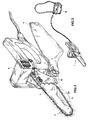
- Figure 1 shows an exploded view of a first embodiment of the device for cutting not according to the invention;
- Figure 2 shows a perspective view of the device of Figure 1 in an assembled condition thereof;
- Figure 3 shows a perspective view of a cutting kit comprising the device of Figure 1;
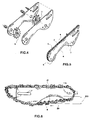
- Figure 4 shows an exploded view of a detail of the device of Figure 1;
- Figure 5 shows a perspective view of the detail of Figure 4;
- Figure 6 shows a front view of the detail of Figure 4; and
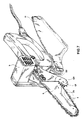
- Figure 7 shows a perspective view of another embodiment of the device for cutting according to the present invention.
- Initially referring to Figures 1 and 2, a device for cutting branches and the like not according to the invention is generally indicated by 1.
- In the present embodiment, the device 1 is an electric saw for the cutting of trees and the like.
- The device 1 comprises a substantially flexible elongate cutting tool 2, having an annular development, which in the present embodiment is a conventional cutting chain.
- Moreover, as it is better visible in Figures 4 to 6, the device 1 comprises a guide 3 shaped according to closed-path, cooperating with the chain 2 in order to guide the cutting motion of the latter. The sense of the cutting motion of the chain 2 onto the guide 3 is indicated by arrows in Figure 6.
- Always referring to Figures 4 to 6, in the present embodiment the guide 3 is an annular track, it also indicated by 3, developing along an elongate path and onto which the chain 2 extends. The track 3 is obtained at a peripheral edge 4 of a substantially flat guide body 5.
- The track 3 has, at a bottom portion thereof, a
recess 6 having a substantially loop-shaped contour, and in particular a substantially sinuous contour, having rounded corners. - The device 1 also comprises means 12, schematically depicted in Figure 1, for tensioning the chain 2 onto the track 3. Said means 12 is of a conventional type, and therefore will not be described in further detail.
- Always referring to Figures 4 to 6, in correspondence of the track 3 the device 1 comprises means for dragging the chain 2, said means being housed within the guide body 5. In the present embodiment the means for dragging is in form of a first and a second sprocket, 7 and 8, respectively, each mounted on a respective bearing, e.g. a needle bearing.
- In particular, the
first sprocket 7 is arranged at a rear mouth of therecess 6, and precisely downstream of the latter with respect to the sense of the cutting motion of the chain 2 onto the track 3. Such an arrangement fosters an effective dragging of the chain 2, as it will be detailed hereinafter. - The
second sprocket 8 is instead arranged at the foremost portion of the guide body 5. - The mounting on bearings of the
sprockets - Further referring to Figures 1 and 2, the device 1 further comprises means for driving the chain 2, apt to slide the latter along the track 3, so as to give it a substantially translatory cutting motion.
- In the present embodiment, the means for driving comprises an
electric motor 9 that drives the chain 2 by interposition of conventional transmission means. - The
motor 9 is powered by means of a battery, e.g. of a rechargeable type. The latter may easily be housed within a bag or pouch M carried or worn-on by the operator, as it is shown in Figure 3. - The
motor 9 can be operated by means of a pushbutton or of an equivalent conventional system. - Of course, in an alternative embodiment the device could provide powering means different from that of the hereto-considered embodiment, e.g., an explosion engine. In fact, the former is more suitable in case the device of the invention consists of an electric saw or the like.
- The device 1 also comprises a protecting
cover 11 for covering the chain 2 when the device itself is not in operation; for simplicity's sake, said protection has been depicted solely in Figure 2. - In the present embodiment, the
cover 11 consists of a sleeve opened lengthwise to receive the chain 2. Such asleeve 11 is rotatably connected, and in particular hinged, onto the chassis of the device 1. Thus, it does not require a separate carrying and can easily be inserted on and taken out of the chain 2. - Moreover, the device 1 comprises a system for lubricating the chain 2 and a side means 13 resting on the piece to be cut, commonly called 'lug', of a conventional type and therefore not described in further detail.
- The operation modes of the device 1 will hereinafter be illustrated with reference to all of the hereto-introduced figures.
- When the operator operates the
motor 9, the chain 2 is induced to slide onto the track 3, following an annular path about the latter. - In operation, the cutting of the piece is performed by an
effective portion 20 of the chain 2 (enclosed within a dashed line in Figure 2) into contact with the piece itself. Sucheffective portion 20 extends at therecess 6 of the track 3, and therefore it is not into contact with the latter. In particular, as it is shown in Figure 6, in operation theeffective portion 20 is substantially spaced apart from said track 3, exhibiting a maximal distance therefrom that is indicated by areference height 203. - It will be understood that the fact that the
effective portion 20 of the chain 2 is not into contact with the guide 3 does not penalize the efficiency and the effectiveness of the cutting, also by virtue of the arrangement of thedragging sprocket 7 immediately downstream of therecess 6. In particular, the cutting action could determine a slight bending of theeffective portion 20 of the chain toward the track 3, without however determining, by virtue of saidsubstantial distance 203, a contact between the two components. On the other hand, such bending of theportion 20 of the chain toward the wall of therecess 6 induces a moving away from the track 3 of aportion 21 of the chain opposite to theeffective portion 20. Evidently, this further reduces the overall friction between slideway 3 and chain 2. - Referring now to Figure 7, according to the invention, the device for cutting comprises a side means 130 resting on the piece to be cut, which is different from the side means 13 of the first embodiment described with reference to the preceding figures.
- In particular, the
means 130 comprises a substantially vertical smooth chute-like edge 132 and asprocket 131 arranged therebelow. According to the invention, thesprocket 131 rotates idle, e.g. above a needle bearing, and it is equipped with teeth apt to engage the piece to be cut, and in particular apt to break into the branch bark. Theidle sprocket 131, by inserting the rotating teeth in the branch bark, annuls vibrations and side shifting of the cutting device, moreover easing the descent of the cutting chain into the cut jointly with thesmooth bank 132 completing the detachment of the branch. - The
smooth edge 132 may also be replaced by plural idle sprockets aligned thereamong. - Moreover, the sprocket or
sprockets 131 may be replaced by any other suitable rotating element. - Lastly, it will be understood that a kit comprising the device 1, the
means 9 for driving, the battery and the bag or pouch M schematically shown in Figure 3 may be provided. - The present invention has hereto been described with reference to a preferred embodiment thereof. It is understood that there could be other embodiments falling within the scope of the claims set forth hereinafter.
Claims (20)
- A device (1) for cutting branches and the like, comprising:- a substantially flexible elongate cutting tool (2);- a guide (3) shaped according to a closed-path, onto which said cutting tool (2) extends; and- driving means (9) for driving said cutting tool (2), apt to slide the latter onto said guide (3) so as to provide it with a cutting motion,wherein, in operation, an effective portion (20) of said tool (2) is in contact with the piece to be cut in order to perform the cutting,
wherein said guide (3) has, at said effective tool portion (20), a recess (6), the overall arrangement being such that at said recess (6) said guide (3) is not in contact with said effective portion (20) of the cutting tool (2)
characterised in that it further comprises a resting means (130) resting on the piece to be cut said resting means in its turn comprising an idle rotating element (131) equipped with teeth apt to engage the piece to be cut. - The device (1) according to claim 1, wherein the overall arrangement is such that at said recess (6) said guide (3) is substantially spaced apart from said effective portion (20) of the cutting tool (2).
- The device (1) according to claim 1 or 2, wherein said cutting tool is an annular cutting chain (2).
- The device (1) according to any one of the preceding claims, wherein said recess (6) of said guide (3) has a substantially loop-shaped contour.
- The device (1) according to the preceding claim, wherein said recess (6) has a substantially sinuous contour, having rounded corners.
- The device (1) according to any one of the preceding claims, wherein said guide comprises a track (3).
- The device (1) according to any one of the preceding claims, comprising a shaped body (5) the peripheral edge of which implements said guide (3).
- The device (1) according to any one of the preceding claims, comprising means (7, 8) for dragging said cutting tool (2), arranged at said guide (3).
- The device (1) according to the preceding claim, wherein said means for dragging comprises a dragging element (7, 8) mounted onto a respective bearing.
- The device (1) according to claim 8 or 9, wherein said means for dragging comprises a dragging element (7) arranged at a mouth of said recess (6).
- The device (1) according to any one of claims 8 to 10, wherein said means for dragging comprises a dragging element (7) arranged downstream of said recess (6) with respect to the sense of the cutting motion of said tool (2) onto said guide (3).
- The device (1) according to any one of claims 8 to 11, wherein said means for dragging comprises at least one guide sprocket (7, 8).
- The device (1) according to any one of the preceding claims, wherein said means for driving comprises an electric motor (9).
- The device (1) according to any one of the claims 1 to 12, wherein said means (9) for driving comprises an explosion engine.
- The device (1) according to any one of the preceding claims, comprising a protecting cover (11) for covering said cutting tool (2).
- The device (1) according to the preceding claim, wherein said protecting cover (11) is rotatably connected to the chassis of the device itself.
- The device (1) according to claim 15 or 16, wherein said protecting cover comprises a sleeve element (11) lengthwise opened to receive said cutting tool (2).
- The device (1) according to any of the preceding claims,
wherein said resting means (130) comprises a plurality of rotating elements (131), each equipped with teeth apt to engage the piece to be cut. - The device (1) according to the preceding claim, wherein the rotating elements (131) of said plurality are arranged aligned thereamong.
- A cutting kit for branches and the like, comprising a device for cutting (1) according to any one of the preceding claims, a battery for powering said means (9) for driving said device (1) and a bag or pouch (M) for housing said battery.
Priority Applications (1)
| Application Number | Priority Date | Filing Date | Title |
|---|---|---|---|
| CY20071101389T CY1106960T1 (en) | 2003-07-30 | 2007-10-29 | DEVICE FOR CUTTING BRANCHES AND OTHER SIMILAR INFORMATION |
Applications Claiming Priority (2)
| Application Number | Priority Date | Filing Date | Title |
|---|---|---|---|
| IT000374A ITRM20030374A1 (en) | 2003-07-30 | 2003-07-30 | CUTTING DEVICE FOR BRANCHES AND THE LIKE. |
| ITRM20030374 | 2003-07-30 |
Publications (3)
| Publication Number | Publication Date |
|---|---|
| EP1502718A2 EP1502718A2 (en) | 2005-02-02 |
| EP1502718A3 EP1502718A3 (en) | 2005-04-13 |
| EP1502718B1 true EP1502718B1 (en) | 2007-08-08 |
Family
ID=29765942
Family Applications (1)
| Application Number | Title | Priority Date | Filing Date |
|---|---|---|---|
| EP04102989A Not-in-force EP1502718B1 (en) | 2003-07-30 | 2004-06-28 | Device for cutting branches and the like |
Country Status (7)
| Country | Link |
|---|---|
| EP (1) | EP1502718B1 (en) |
| AT (1) | ATE369237T1 (en) |
| CY (1) | CY1106960T1 (en) |
| DE (1) | DE602004007990D1 (en) |
| ES (1) | ES2290627T3 (en) |
| IT (1) | ITRM20030374A1 (en) |
| PT (1) | PT1502718E (en) |
Cited By (1)
| Publication number | Priority date | Publication date | Assignee | Title |
|---|---|---|---|---|
| JP2013522090A (en) * | 2010-03-23 | 2013-06-13 | ブライアン ジェイ ルース | Chainsaw engraving guide bar |
Families Citing this family (3)
| Publication number | Priority date | Publication date | Assignee | Title |
|---|---|---|---|---|
| FR2925384B1 (en) * | 2007-12-20 | 2011-11-18 | Pellenc Sa | PORTABLE ELECTRIC CHAIN SAW |
| CA2795488C (en) | 2010-04-16 | 2019-02-19 | Anthony Baratta | Chain bar apparatus and methods and tool combinations and methods of making and using moving tool combinations |
| WO2016086987A1 (en) * | 2014-12-03 | 2016-06-09 | V-Cut Ab | Guiding device for a power driven saw |
Family Cites Families (11)
| Publication number | Priority date | Publication date | Assignee | Title |
|---|---|---|---|---|
| US1825164A (en) * | 1930-05-31 | 1931-09-29 | Skillman Clarence | Portable saw |
| US2572405A (en) * | 1948-05-25 | 1951-10-23 | Albert F Stone | Turret-mounted chain-saw holding claw |
| NO147370C (en) * | 1981-03-26 | 1983-03-30 | Norcem As | ADDITIONAL EQUIPMENT FOR MOTOR POWERED CHAIN. |
| SE450356B (en) * | 1982-06-21 | 1987-06-22 | Osa Ab | SET FOR CUTTING OF HANGING SIGNIFICANT HORIZONTAL ITEMS SUCH AS STOCKS AND SIMILAR, AND DEVICE FOR EXECUTING THE SET |
| US4558518A (en) * | 1982-12-30 | 1985-12-17 | Morabit Vincent D | Tip stabilizing device for a chain saw |
| FR2555093B1 (en) * | 1983-11-23 | 1986-12-26 | Horst Sellmaier | CHAINSAW GUIDE |
| US4760646A (en) * | 1987-01-09 | 1988-08-02 | Frederick Siegler | Tree pruner and hedge trimmer |
| DE9116053U1 (en) * | 1991-12-24 | 1992-02-20 | Discher, Hannelore, 3501 Niedenstein, De | |
| US5685080A (en) * | 1996-04-22 | 1997-11-11 | Makita Corporation | Battery powered chain saw |
| US5826343A (en) * | 1996-10-22 | 1998-10-27 | Kinetic Stump Cutter, Inc. | Chain saw attachment |
| ITFG990003A1 (en) * | 1999-02-22 | 2000-08-22 | Marco Cecchi | ALTERNATIVE ELECTRIC SAW, WITH TOOTHED BLADE SUPPORTED BY PENDULUM ARMS, WITH BLADE COVER SHEATH AND REVOLVING PINK COVER SUPPORT |
-
2003
- 2003-07-30 IT IT000374A patent/ITRM20030374A1/en unknown
-
2004
- 2004-06-28 ES ES04102989T patent/ES2290627T3/en active Active
- 2004-06-28 DE DE602004007990T patent/DE602004007990D1/en active Active
- 2004-06-28 PT PT04102989T patent/PT1502718E/en unknown
- 2004-06-28 AT AT04102989T patent/ATE369237T1/en not_active IP Right Cessation
- 2004-06-28 EP EP04102989A patent/EP1502718B1/en not_active Not-in-force
-
2007
- 2007-10-29 CY CY20071101389T patent/CY1106960T1/en unknown
Cited By (1)
| Publication number | Priority date | Publication date | Assignee | Title |
|---|---|---|---|---|
| JP2013522090A (en) * | 2010-03-23 | 2013-06-13 | ブライアン ジェイ ルース | Chainsaw engraving guide bar |
Also Published As
| Publication number | Publication date |
|---|---|
| DE602004007990D1 (en) | 2007-09-20 |
| EP1502718A3 (en) | 2005-04-13 |
| CY1106960T1 (en) | 2012-09-26 |
| ES2290627T3 (en) | 2008-02-16 |
| PT1502718E (en) | 2007-11-09 |
| EP1502718A2 (en) | 2005-02-02 |
| ATE369237T1 (en) | 2007-08-15 |
| ITRM20030374A1 (en) | 2005-01-31 |
| ITRM20030374A0 (en) | 2003-07-30 |
Similar Documents
| Publication | Publication Date | Title |
|---|---|---|
| US20240123649A1 (en) | Powered handheld cutting tool | |
| US5685080A (en) | Battery powered chain saw | |
| US20140047722A1 (en) | Chain saw | |
| FR2721546B1 (en) | Handle device for a chain motor saw. | |
| EP1281465B1 (en) | Cutting tool having lighting devices | |
| EP1502718B1 (en) | Device for cutting branches and the like | |
| EP3509415B1 (en) | Improved branch cutter | |
| EP1400296A3 (en) | Dust collection mechanism for a miter saw | |
| FR2702170B1 (en) | SABER SAW DRIVEN BY A MOTOR. | |
| JP2008018498A (en) | Cutter | |
| JP4067158B2 (en) | Portable circular saw | |
| US5609085A (en) | Cutting device with a pivotable cover for covering an exposed cutting portion | |
| US20060283023A1 (en) | Cutting apparatus | |
| EP0993767A3 (en) | Guide bar mount for a tree harvester | |
| US20020100827A1 (en) | Paper shredder | |
| US4654972A (en) | Power saw blade | |
| ATE336345T1 (en) | CUT SAW | |
| US4993856A (en) | Paper cutting device for a printer | |
| US20040140382A1 (en) | Paper shredder | |
| DE69929404D1 (en) | Battery operated portable circular saw with cutting depth adjuster | |
| EP1759576A3 (en) | Lawnmower | |
| US8006884B2 (en) | Hammer tacker | |
| ATE270602T1 (en) | ELECTRICAL HAND TOOLS | |
| DE69800043D1 (en) | Drive device for lawn mowers | |
| FR2661066A1 (en) | Lawnmower device with an electric motor powered by a battery |
Legal Events
| Date | Code | Title | Description |
|---|---|---|---|
| PUAI | Public reference made under article 153(3) epc to a published international application that has entered the european phase |
Free format text: ORIGINAL CODE: 0009012 |
|
| AK | Designated contracting states |
Kind code of ref document: A2 Designated state(s): AT BE BG CH CY CZ DE DK EE ES FI FR GB GR HU IE IT LI LU MC NL PL PT RO SE SI SK TR |
|
| AX | Request for extension of the european patent |
Extension state: AL HR LT LV MK |
|
| PUAL | Search report despatched |
Free format text: ORIGINAL CODE: 0009013 |
|
| RIC1 | Information provided on ipc code assigned before grant |
Ipc: 7B 27B 17/02 A Ipc: 7B 27B 17/00 B |
|
| AK | Designated contracting states |
Kind code of ref document: A3 Designated state(s): AT BE BG CH CY CZ DE DK EE ES FI FR GB GR HU IE IT LI LU MC NL PL PT RO SE SI SK TR |
|
| AX | Request for extension of the european patent |
Extension state: AL HR LT LV MK |
|
| 17P | Request for examination filed |
Effective date: 20050704 |
|
| AKX | Designation fees paid |
Designated state(s): AT BE BG CH CY CZ DE DK EE ES FI FR GB GR HU IE IT LI LU MC NL PL PT RO SE SI SK TR |
|
| GRAP | Despatch of communication of intention to grant a patent |
Free format text: ORIGINAL CODE: EPIDOSNIGR1 |
|
| GRAS | Grant fee paid |
Free format text: ORIGINAL CODE: EPIDOSNIGR3 |
|
| GRAA | (expected) grant |
Free format text: ORIGINAL CODE: 0009210 |
|
| AK | Designated contracting states |
Kind code of ref document: B1 Designated state(s): AT BE BG CH CY CZ DE DK EE ES FI FR GB GR HU IE IT LI LU MC NL PL PT RO SE SI SK TR |
|
| REG | Reference to a national code |
Ref country code: GB Ref legal event code: FG4D |
|
| REG | Reference to a national code |
Ref country code: CH Ref legal event code: EP |
|
| REG | Reference to a national code |
Ref country code: IE Ref legal event code: FG4D |
|
| REF | Corresponds to: |
Ref document number: 602004007990 Country of ref document: DE Date of ref document: 20070920 Kind code of ref document: P |
|
| REG | Reference to a national code |
Ref country code: PT Ref legal event code: SC4A Free format text: AVAILABILITY OF NATIONAL TRANSLATION Effective date: 20071026 |
|
| REG | Reference to a national code |
Ref country code: GR Ref legal event code: EP Ref document number: 20070403179 Country of ref document: GR |
|
| ET | Fr: translation filed | ||
| PG25 | Lapsed in a contracting state [announced via postgrant information from national office to epo] |
Ref country code: BG Free format text: LAPSE BECAUSE OF FAILURE TO SUBMIT A TRANSLATION OF THE DESCRIPTION OR TO PAY THE FEE WITHIN THE PRESCRIBED TIME-LIMIT Effective date: 20071108 Ref country code: NL Free format text: LAPSE BECAUSE OF FAILURE TO SUBMIT A TRANSLATION OF THE DESCRIPTION OR TO PAY THE FEE WITHIN THE PRESCRIBED TIME-LIMIT Effective date: 20070808 Ref country code: FI Free format text: LAPSE BECAUSE OF FAILURE TO SUBMIT A TRANSLATION OF THE DESCRIPTION OR TO PAY THE FEE WITHIN THE PRESCRIBED TIME-LIMIT Effective date: 20070808 |
|
| NLV1 | Nl: lapsed or annulled due to failure to fulfill the requirements of art. 29p and 29m of the patents act | ||
| REG | Reference to a national code |
Ref country code: CH Ref legal event code: PL |
|
| REG | Reference to a national code |
Ref country code: ES Ref legal event code: FG2A Ref document number: 2290627 Country of ref document: ES Kind code of ref document: T3 |
|
| PG25 | Lapsed in a contracting state [announced via postgrant information from national office to epo] |
Ref country code: AT Free format text: LAPSE BECAUSE OF FAILURE TO SUBMIT A TRANSLATION OF THE DESCRIPTION OR TO PAY THE FEE WITHIN THE PRESCRIBED TIME-LIMIT Effective date: 20070808 Ref country code: LI Free format text: LAPSE BECAUSE OF FAILURE TO SUBMIT A TRANSLATION OF THE DESCRIPTION OR TO PAY THE FEE WITHIN THE PRESCRIBED TIME-LIMIT Effective date: 20070808 Ref country code: PL Free format text: LAPSE BECAUSE OF FAILURE TO SUBMIT A TRANSLATION OF THE DESCRIPTION OR TO PAY THE FEE WITHIN THE PRESCRIBED TIME-LIMIT Effective date: 20070808 Ref country code: CH Free format text: LAPSE BECAUSE OF FAILURE TO SUBMIT A TRANSLATION OF THE DESCRIPTION OR TO PAY THE FEE WITHIN THE PRESCRIBED TIME-LIMIT Effective date: 20070808 |
|
| PG25 | Lapsed in a contracting state [announced via postgrant information from national office to epo] |
Ref country code: BE Free format text: LAPSE BECAUSE OF FAILURE TO SUBMIT A TRANSLATION OF THE DESCRIPTION OR TO PAY THE FEE WITHIN THE PRESCRIBED TIME-LIMIT Effective date: 20070808 |
|
| PG25 | Lapsed in a contracting state [announced via postgrant information from national office to epo] |
Ref country code: DK Free format text: LAPSE BECAUSE OF FAILURE TO SUBMIT A TRANSLATION OF THE DESCRIPTION OR TO PAY THE FEE WITHIN THE PRESCRIBED TIME-LIMIT Effective date: 20070808 |
|
| PG25 | Lapsed in a contracting state [announced via postgrant information from national office to epo] |
Ref country code: CZ Free format text: LAPSE BECAUSE OF FAILURE TO SUBMIT A TRANSLATION OF THE DESCRIPTION OR TO PAY THE FEE WITHIN THE PRESCRIBED TIME-LIMIT Effective date: 20070808 Ref country code: SK Free format text: LAPSE BECAUSE OF FAILURE TO SUBMIT A TRANSLATION OF THE DESCRIPTION OR TO PAY THE FEE WITHIN THE PRESCRIBED TIME-LIMIT Effective date: 20070808 |
|
| PLBE | No opposition filed within time limit |
Free format text: ORIGINAL CODE: 0009261 |
|
| STAA | Information on the status of an ep patent application or granted ep patent |
Free format text: STATUS: NO OPPOSITION FILED WITHIN TIME LIMIT |
|
| PG25 | Lapsed in a contracting state [announced via postgrant information from national office to epo] |
Ref country code: SE Free format text: LAPSE BECAUSE OF FAILURE TO SUBMIT A TRANSLATION OF THE DESCRIPTION OR TO PAY THE FEE WITHIN THE PRESCRIBED TIME-LIMIT Effective date: 20071108 Ref country code: RO Free format text: LAPSE BECAUSE OF FAILURE TO SUBMIT A TRANSLATION OF THE DESCRIPTION OR TO PAY THE FEE WITHIN THE PRESCRIBED TIME-LIMIT Effective date: 20070808 |
|
| 26N | No opposition filed |
Effective date: 20080509 |
|
| PG25 | Lapsed in a contracting state [announced via postgrant information from national office to epo] |
Ref country code: DE Free format text: LAPSE BECAUSE OF FAILURE TO SUBMIT A TRANSLATION OF THE DESCRIPTION OR TO PAY THE FEE WITHIN THE PRESCRIBED TIME-LIMIT Effective date: 20071109 |
|
| PG25 | Lapsed in a contracting state [announced via postgrant information from national office to epo] |
Ref country code: MC Free format text: LAPSE BECAUSE OF NON-PAYMENT OF DUE FEES Effective date: 20080630 |
|
| GBPC | Gb: european patent ceased through non-payment of renewal fee |
Effective date: 20080628 |
|
| PG25 | Lapsed in a contracting state [announced via postgrant information from national office to epo] |
Ref country code: EE Free format text: LAPSE BECAUSE OF FAILURE TO SUBMIT A TRANSLATION OF THE DESCRIPTION OR TO PAY THE FEE WITHIN THE PRESCRIBED TIME-LIMIT Effective date: 20070808 Ref country code: IE Free format text: LAPSE BECAUSE OF NON-PAYMENT OF DUE FEES Effective date: 20080630 |
|
| PG25 | Lapsed in a contracting state [announced via postgrant information from national office to epo] |
Ref country code: SI Free format text: LAPSE BECAUSE OF FAILURE TO SUBMIT A TRANSLATION OF THE DESCRIPTION OR TO PAY THE FEE WITHIN THE PRESCRIBED TIME-LIMIT Effective date: 20070808 Ref country code: GB Free format text: LAPSE BECAUSE OF NON-PAYMENT OF DUE FEES Effective date: 20080628 |
|
| PGFP | Annual fee paid to national office [announced via postgrant information from national office to epo] |
Ref country code: ES Payment date: 20090624 Year of fee payment: 6 |
|
| PGFP | Annual fee paid to national office [announced via postgrant information from national office to epo] |
Ref country code: FR Payment date: 20090615 Year of fee payment: 6 Ref country code: PT Payment date: 20090605 Year of fee payment: 6 |
|
| PGFP | Annual fee paid to national office [announced via postgrant information from national office to epo] |
Ref country code: GR Payment date: 20090629 Year of fee payment: 6 |
|
| PGFP | Annual fee paid to national office [announced via postgrant information from national office to epo] |
Ref country code: CY Payment date: 20090609 Year of fee payment: 6 |
|
| PG25 | Lapsed in a contracting state [announced via postgrant information from national office to epo] |
Ref country code: LU Free format text: LAPSE BECAUSE OF NON-PAYMENT OF DUE FEES Effective date: 20080628 Ref country code: HU Free format text: LAPSE BECAUSE OF FAILURE TO SUBMIT A TRANSLATION OF THE DESCRIPTION OR TO PAY THE FEE WITHIN THE PRESCRIBED TIME-LIMIT Effective date: 20080209 |
|
| PG25 | Lapsed in a contracting state [announced via postgrant information from national office to epo] |
Ref country code: TR Free format text: LAPSE BECAUSE OF FAILURE TO SUBMIT A TRANSLATION OF THE DESCRIPTION OR TO PAY THE FEE WITHIN THE PRESCRIBED TIME-LIMIT Effective date: 20070808 |
|
| REG | Reference to a national code |
Ref country code: PT Ref legal event code: MM4A Free format text: LAPSE DUE TO NON-PAYMENT OF FEES Effective date: 20101228 |
|
| PG25 | Lapsed in a contracting state [announced via postgrant information from national office to epo] |
Ref country code: CY Free format text: LAPSE BECAUSE OF NON-PAYMENT OF DUE FEES Effective date: 20100628 Ref country code: PT Free format text: LAPSE BECAUSE OF NON-PAYMENT OF DUE FEES Effective date: 20101228 |
|
| REG | Reference to a national code |
Ref country code: FR Ref legal event code: ST Effective date: 20110228 |
|
| PG25 | Lapsed in a contracting state [announced via postgrant information from national office to epo] |
Ref country code: FR Free format text: LAPSE BECAUSE OF NON-PAYMENT OF DUE FEES Effective date: 20100630 |
|
| PGFP | Annual fee paid to national office [announced via postgrant information from national office to epo] |
Ref country code: IT Payment date: 20110215 Year of fee payment: 8 |
|
| PG25 | Lapsed in a contracting state [announced via postgrant information from national office to epo] |
Ref country code: GR Free format text: LAPSE BECAUSE OF NON-PAYMENT OF DUE FEES Effective date: 20110104 |
|
| REG | Reference to a national code |
Ref country code: ES Ref legal event code: FD2A Effective date: 20110715 |
|
| PG25 | Lapsed in a contracting state [announced via postgrant information from national office to epo] |
Ref country code: ES Free format text: LAPSE BECAUSE OF NON-PAYMENT OF DUE FEES Effective date: 20110705 |
|
| PG25 | Lapsed in a contracting state [announced via postgrant information from national office to epo] |
Ref country code: ES Free format text: LAPSE BECAUSE OF NON-PAYMENT OF DUE FEES Effective date: 20100629 |
|
| PG25 | Lapsed in a contracting state [announced via postgrant information from national office to epo] |
Ref country code: IT Free format text: LAPSE BECAUSE OF NON-PAYMENT OF DUE FEES Effective date: 20120628 |
|
| REG | Reference to a national code |
Ref country code: GR Ref legal event code: ML Ref document number: 20070403179 Country of ref document: GR Effective date: 20110104 |