EP1502698A2 - Rotationsförderer zum Entfernen von Metallspänen, die bei mechanischen Arbeitsvorgängen entstehen - Google Patents
Rotationsförderer zum Entfernen von Metallspänen, die bei mechanischen Arbeitsvorgängen entstehen Download PDFInfo
- Publication number
- EP1502698A2 EP1502698A2 EP03028820A EP03028820A EP1502698A2 EP 1502698 A2 EP1502698 A2 EP 1502698A2 EP 03028820 A EP03028820 A EP 03028820A EP 03028820 A EP03028820 A EP 03028820A EP 1502698 A2 EP1502698 A2 EP 1502698A2
- Authority
- EP
- European Patent Office
- Prior art keywords
- basket
- shavings
- bottom wall
- conveyor member
- rotation
- Prior art date
- Legal status (The legal status is an assumption and is not a legal conclusion. Google has not performed a legal analysis and makes no representation as to the accuracy of the status listed.)
- Granted
Links
Images


Classifications
-
- B—PERFORMING OPERATIONS; TRANSPORTING
- B23—MACHINE TOOLS; METAL-WORKING NOT OTHERWISE PROVIDED FOR
- B23Q—DETAILS, COMPONENTS, OR ACCESSORIES FOR MACHINE TOOLS, e.g. ARRANGEMENTS FOR COPYING OR CONTROLLING; MACHINE TOOLS IN GENERAL CHARACTERISED BY THE CONSTRUCTION OF PARTICULAR DETAILS OR COMPONENTS; COMBINATIONS OR ASSOCIATIONS OF METAL-WORKING MACHINES, NOT DIRECTED TO A PARTICULAR RESULT
- B23Q11/00—Accessories fitted to machine tools for keeping tools or parts of the machine in good working condition or for cooling work; Safety devices specially combined with or arranged in, or specially adapted for use in connection with, machine tools
- B23Q11/0042—Devices for removing chips
- B23Q11/0057—Devices for removing chips outside the working area
-
- B—PERFORMING OPERATIONS; TRANSPORTING
- B65—CONVEYING; PACKING; STORING; HANDLING THIN OR FILAMENTARY MATERIAL
- B65G—TRANSPORT OR STORAGE DEVICES, e.g. CONVEYORS FOR LOADING OR TIPPING, SHOP CONVEYOR SYSTEMS OR PNEUMATIC TUBE CONVEYORS
- B65G53/00—Conveying materials in bulk through troughs, pipes or tubes by floating the materials or by flow of gas, liquid or foam
- B65G53/34—Details
- B65G53/40—Feeding or discharging devices
- B65G53/48—Screws or like rotary conveyors
Definitions
- the present invention relates to a device for evacuating metal shavings resulting from machining processing plants by means of cutting machine tools. More in particular, the invention relates to a device for evacuating shavings of the rotating conveyor type, comprising a collecting container having an inlet opening for the entry of the shavings, a basket mounted to rotate in the collecting container about a vertical axis of rotation and having a bottom wall located underneath said inlet opening, motorised means for driving rotation of the basket, an evacuation conduit connected to an aspiration unit and having a lower end which terminates inside said collecting container above said bottom wall in offset position relative to the vertical axis of rotation of the basket, and a stationary conveyor member designed, during the rotation of the basket, to convey the shavings below the aforesaid lower end of the evacuation conduit.
- a rotating conveyor device of the kind described above is known from the German utility model DE-20304348U by the same Applicant.
- the conveyor member consists of a contour blade positioned immediately above the bottom wall of the basket between the axis of rotation thereof and the aforesaid lower end of the evacuation conduit. More in particular, the blade is fastened to the bottom end of the evacuation conduit and its location is fixed, i.e. it cannot be modified.
- the present invention constitutes an enhancement of the known realisation of the aforesaid German utility model, and in particular its aim is to allow a practical and easy adaptation of the rotating conveyor to shavings with different characteristics, for instance in terms of shapes and dimensions.
- this aim is achieved thanks to the fact that the aforesaid blade conveyor member is angularly adjustable.
- the capability of angularly adjusting the blade conveyor member allows to vary its position relative to the lower end of the intake conduit, in such a way as to reduce or enlarge the port for the passage of the shavings towards said lower end of the intake conduit according to the specific characteristics of the shavings. This allows to optimise the action of evacuating the shavings from the collecting container, avoiding jams and more in general malfunctions.
- the blade conveyor member is borne by an end of a tubular support, coaxial to the aforesaid axis of rotation of the basket and having at the other end apart for the attachment to said container in different selectable positions.
- the number 1 globally designates a rotating conveyor device for the pneumatic (or hydraulic) evacuation of metal shavings coming from cutting machine tools.
- the device 1 can advantageously be operatively associated to a self-fed triturating device of the type described and illustrated in European patent application EP-A-1151822 by the same Applicant.
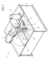
- the device 1 essentially comprises a collecting container 2, for instance of generally parallelepiped shape, having an upper opening 3 through which the triturated shavings are fed by gravity (or with different insertion system) to a basket 4 mounted able to rotate inside the collecting container 2 about a vertical axis A.
- the gear motor 7 commands in rotation a vertical shaft 8, positioned along the axis A, which traverses the bottom wall 5 of the basket 4 and is torsionally coupled therewith in 9.
- the bottom wall 5 of the basket 4 has a plurality of substantially radial projections 10 positioned starting from its periphery.
- the number and the arrangement of the projections 10 may vary relative to what is described by way of example with reference to the figures.
- the reference number 11 designates an evacuation conduit connected to a pneumatic (or hydraulic) intake unit, not shown herein, known to those versed in the art, advantageously through a pipeline or through a series of overhead pipelines.
- the evacuation conduit 11 extends vertically within the collecting container 2 and in an offset position relative to the vertical axis of rotation A of the basket 4. Said position substantially corresponds to the periphery of the bottom wall 5 bearing the radial projections 10.
- the bottom end of the evacuation conduit 11, designated by the reference number 12, is positioned above the bottom wall 5 and it can have a bevelled edge.
- the reference number 13 designates a stationary conveyor member constituted by a shaped blade positioned immediately above the bottom wall 5 of the basket 4 between the vertical axis A and the bottom end 12 of the evacuation conduit 11.
- the conveyor blade 13 has a general convex shape, with an attachment end 13a and a free end 13b.
- the attachment end 13a is rigidly fastened to the lower end 14a of a tubular support 14 which coaxially surrounds the vertical shaft 8 along the axis A.
- the upper end of the tubular support 14 has a radial flange 15 serving for its fastening to a support cross member 16 fastened above the container 2.
- Such fastening is achieved by means of one or more screws 17 capable of being selectively engaged in a series of holes 18 of the supporting cross member 16 and through a hole 19 of the flange 15 of the tubular support 14.
- screws 17 capable of being selectively engaged in a series of holes 18 of the supporting cross member 16 and through a hole 19 of the flange 15 of the tubular support 14.
- Said variation allows to position the free end 13b of the conveyor blade 13 at a greater or smaller distance from the lower end 12 of the evacuation conduit 11, in optimised fashion according to the characteristics of shape and dimensions of the shavings fed to the device.
- the reference number 20 lastly designates a ploughshare shaped deflector fastened to the container 2 above the bottom wall 5 of the basket 4, between the end 13b of the conveyor blade 13 and the lower end 12 of the evacuation conduit 11.
- Said deflector 20 can be adjustable in height according to the characteristics of the shavings fed to the device.
- the triturated shavings inserted into the collecting container 2 through the upper opening 3 are deposited on the bottom wall 5 of the basket 4.
- the basket 4 is made to rotate clockwise with reference to the drawings, in such a way as to transfer the shavings towards the conveyor blade 13, thereby concentrating them underneath the lower end 12 of the evacuation conduit 11.
- the radial projections 10 act, during the rotation of the basket 4, in such a way as to move the shavings accumulated or concentrated by the blade 13 underneath the end 12 of the conduit 11, which is cyclically placed in communication with the aspiration unit to remove the shavings from the collecting container 2 and to transfer them to the overhead evacuation system.
- the unit for aspirating the shavings can be either pneumatic or hydraulic.
- a hydraulic pump shall be positioned for example within the rotating the basket 4, and the shavings may be inserted into the collecting container 2 even without being preventively subjected to oil removal treatments.
Landscapes
- Mechanical Engineering (AREA)
- Engineering & Computer Science (AREA)
- Crushing And Pulverization Processes (AREA)
- Finish Polishing, Edge Sharpening, And Grinding By Specific Grinding Devices (AREA)
- Filling Or Emptying Of Bunkers, Hoppers, And Tanks (AREA)
- Baking, Grill, Roasting (AREA)
- Gasification And Melting Of Waste (AREA)
- Gas Burners (AREA)
- Auxiliary Devices For Machine Tools (AREA)
- Combined Means For Separation Of Solids (AREA)
- Manufacture And Refinement Of Metals (AREA)
- Sampling And Sample Adjustment (AREA)
- Disintegrating Or Milling (AREA)
- Screw Conveyors (AREA)
- Devices For Opening Bottles Or Cans (AREA)
Applications Claiming Priority (2)
| Application Number | Priority Date | Filing Date | Title |
|---|---|---|---|
| IT000592A ITTO20030592A1 (it) | 2003-07-31 | 2003-07-31 | Convogliatore rotante per l'evacuazione di truccioli |
| ITTO20030592 | 2003-07-31 |
Publications (3)
| Publication Number | Publication Date |
|---|---|
| EP1502698A2 true EP1502698A2 (de) | 2005-02-02 |
| EP1502698A3 EP1502698A3 (de) | 2005-11-16 |
| EP1502698B1 EP1502698B1 (de) | 2007-01-24 |
Family
ID=32089027
Family Applications (1)
| Application Number | Title | Priority Date | Filing Date |
|---|---|---|---|
| EP03028820A Expired - Lifetime EP1502698B1 (de) | 2003-07-31 | 2003-12-15 | Rotationsförderer zum Entfernen von Metallspänen, die bei mechanischen Arbeitsvorgängen entstehen |
Country Status (6)
| Country | Link |
|---|---|
| US (1) | US6846134B1 (de) |
| EP (1) | EP1502698B1 (de) |
| AT (1) | ATE352398T1 (de) |
| BR (1) | BRPI0400032A (de) |
| DE (2) | DE60311448D1 (de) |
| IT (1) | ITTO20030592A1 (de) |
Families Citing this family (3)
| Publication number | Priority date | Publication date | Assignee | Title |
|---|---|---|---|---|
| US7824514B2 (en) | 2005-12-01 | 2010-11-02 | The Procter & Gamble Company | Method of producing a stretch laminate |
| FR3035090B1 (fr) * | 2015-04-16 | 2017-03-31 | Sidel Participations | "dispositif d'alignement et de redressement de preformes comportant un bol de centrifugeuse equipe de moyens d'ejection de preformes mal alignees" |
| CN114873009B (zh) * | 2022-05-13 | 2024-06-14 | 马鞍山市华茂机械科技有限公司 | 一种刨花打包装置 |
Family Cites Families (8)
| Publication number | Priority date | Publication date | Assignee | Title |
|---|---|---|---|---|
| DE1274081B (de) * | 1958-08-22 | 1968-08-01 | Siemens Ag | Drehstroemungswirbler zum Trennen von Medien unterschiedlicher Dichte |
| US3722698A (en) * | 1970-11-04 | 1973-03-27 | Fmc Corp | Circular clarifier mechanism |
| US4635408A (en) * | 1982-11-30 | 1987-01-13 | Air Products And Chemicals, Inc. | Discharge of blasting media from a treating chamber |
| US4746250A (en) * | 1983-12-13 | 1988-05-24 | Fritz Schoppe | Device for introducing a dosed quantity of powder into a carrier gas stream |
| FI80303C (fi) * | 1986-11-28 | 1991-04-10 | Ahlstroem Oy | Tjockmassatorn. |
| JP2954800B2 (ja) * | 1993-01-13 | 1999-09-27 | 榎本工業株式会社 | 固形体回収装置 |
| DE29510514U1 (de) * | 1995-06-29 | 1995-10-26 | Alpirsbacher Maschinenbau GmbH & Co.KG, 72275 Alpirsbach | Sammelbehälter mit Transportpumpe |
| EP1195223B1 (de) * | 2000-10-05 | 2003-04-09 | TBE Habermehl Anlagenbau GmbH & Co. KG | Sammelbehälter für Schüttgut mit einer Transportpumpe oder einem Absaugrohr |
-
2003
- 2003-07-31 IT IT000592A patent/ITTO20030592A1/it unknown
- 2003-12-15 EP EP03028820A patent/EP1502698B1/de not_active Expired - Lifetime
- 2003-12-15 AT AT03028820T patent/ATE352398T1/de not_active IP Right Cessation
- 2003-12-15 DE DE60311448T patent/DE60311448D1/de not_active Expired - Lifetime
-
2004
- 2004-01-12 BR BR0400032-3A patent/BRPI0400032A/pt not_active Application Discontinuation
- 2004-01-22 DE DE202004000952U patent/DE202004000952U1/de not_active Expired - Lifetime
- 2004-01-26 US US10/763,161 patent/US6846134B1/en not_active Expired - Lifetime
Also Published As
| Publication number | Publication date |
|---|---|
| ITTO20030592A1 (it) | 2005-02-01 |
| ATE352398T1 (de) | 2007-02-15 |
| BRPI0400032A (pt) | 2005-05-24 |
| EP1502698B1 (de) | 2007-01-24 |
| US6846134B1 (en) | 2005-01-25 |
| DE60311448D1 (de) | 2007-03-15 |
| DE202004000952U1 (de) | 2004-04-01 |
| EP1502698A3 (de) | 2005-11-16 |
| US20050025583A1 (en) | 2005-02-03 |
Similar Documents
| Publication | Publication Date | Title |
|---|---|---|
| US7047647B1 (en) | Hand-held power tool with a suction device | |
| EP1502698B1 (de) | Rotationsförderer zum Entfernen von Metallspänen, die bei mechanischen Arbeitsvorgängen entstehen | |
| EP3822055B1 (de) | Motorbetriebenes werkzeug | |
| US6135174A (en) | Lathe cutter and chip fan | |
| EP1151822B1 (de) | Selbstgespeiste Zerkleinerungsvorrichtung für Werkzeugmaschinen mit Späneentfernung | |
| CN210908946U (zh) | 发动机前支架打磨切割装置 | |
| EP0054823A2 (de) | Maschine zum Zerkleinern und Sterilisieren von festem Abfall oder Müll, insbesondere für Krankenhäuser und dergleichen | |
| EP1430993B1 (de) | Umlaufförderer für die Abfuhr von aus mechanischen Bearbeitungsvorgängen resultierenden Metallspänen | |
| US4760967A (en) | Mulcher-chopper | |
| CN208814047U (zh) | 尾板自翻转式粉条加工输送线 | |
| CN213827317U (zh) | 一种矿山机械生产用高效切削装置 | |
| US20070001039A1 (en) | Comminution mill | |
| CN219990288U (zh) | 一种湿料螺旋称重给料机 | |
| CA2272013C (en) | Lathe cutter and chip fan | |
| CN220330701U (zh) | 一种车床刀具的废屑清洁装置 | |
| CN223588899U (zh) | 一种轴类零件的多工位车床 | |
| CN214870751U (zh) | 一种食材切段机 | |
| US20140306045A1 (en) | Device for shredding, collecting and transporting shredded material | |
| CN207105088U (zh) | 一种可拆卸式离心切料机构的多功能切料装置 | |
| CN216000682U (zh) | 一种可收集废料的纸板裁切机 | |
| US2738635A (en) | Grass cutter and blower | |
| CN212291956U (zh) | 一种废纸收集系统 | |
| CN223656599U (zh) | 一种多工位数控车床 | |
| CN222988977U (zh) | 一种易撕盖废料回收装置 | |
| CN116021334B (zh) | 一种用于车轴加工机床的自动除屑装置 |
Legal Events
| Date | Code | Title | Description |
|---|---|---|---|
| PUAI | Public reference made under article 153(3) epc to a published international application that has entered the european phase |
Free format text: ORIGINAL CODE: 0009012 |
|
| AK | Designated contracting states |
Kind code of ref document: A2 Designated state(s): AT BE BG CH CY CZ DE DK EE ES FI FR GB GR HU IE IT LI LU MC NL PT RO SE SI SK TR |
|
| AX | Request for extension of the european patent |
Extension state: AL LT LV MK |
|
| PUAL | Search report despatched |
Free format text: ORIGINAL CODE: 0009013 |
|
| AK | Designated contracting states |
Kind code of ref document: A3 Designated state(s): AT BE BG CH CY CZ DE DK EE ES FI FR GB GR HU IE IT LI LU MC NL PT RO SE SI SK TR |
|
| AX | Request for extension of the european patent |
Extension state: AL LT LV MK |
|
| RIC1 | Information provided on ipc code assigned before grant |
Ipc: 7B 65G 29/00 B Ipc: 7B 65G 53/48 B Ipc: 7B 23Q 11/00 A |
|
| 17P | Request for examination filed |
Effective date: 20060328 |
|
| AKX | Designation fees paid |
Designated state(s): AT BE BG CH CY CZ DE DK EE ES FI FR GB GR HU IE IT LI LU MC NL PT RO SE SI SK TR |
|
| GRAP | Despatch of communication of intention to grant a patent |
Free format text: ORIGINAL CODE: EPIDOSNIGR1 |
|
| GRAS | Grant fee paid |
Free format text: ORIGINAL CODE: EPIDOSNIGR3 |
|
| GRAA | (expected) grant |
Free format text: ORIGINAL CODE: 0009210 |
|
| AK | Designated contracting states |
Kind code of ref document: B1 Designated state(s): AT BE BG CH CY CZ DE DK EE ES FI FR GB GR HU IE IT LI LU MC NL PT RO SE SI SK TR |
|
| PG25 | Lapsed in a contracting state [announced via postgrant information from national office to epo] |
Ref country code: NL Free format text: LAPSE BECAUSE OF FAILURE TO SUBMIT A TRANSLATION OF THE DESCRIPTION OR TO PAY THE FEE WITHIN THE PRESCRIBED TIME-LIMIT Effective date: 20070124 Ref country code: CH Free format text: LAPSE BECAUSE OF FAILURE TO SUBMIT A TRANSLATION OF THE DESCRIPTION OR TO PAY THE FEE WITHIN THE PRESCRIBED TIME-LIMIT Effective date: 20070124 Ref country code: DK Free format text: LAPSE BECAUSE OF FAILURE TO SUBMIT A TRANSLATION OF THE DESCRIPTION OR TO PAY THE FEE WITHIN THE PRESCRIBED TIME-LIMIT Effective date: 20070124 Ref country code: LI Free format text: LAPSE BECAUSE OF FAILURE TO SUBMIT A TRANSLATION OF THE DESCRIPTION OR TO PAY THE FEE WITHIN THE PRESCRIBED TIME-LIMIT Effective date: 20070124 Ref country code: FI Free format text: LAPSE BECAUSE OF FAILURE TO SUBMIT A TRANSLATION OF THE DESCRIPTION OR TO PAY THE FEE WITHIN THE PRESCRIBED TIME-LIMIT Effective date: 20070124 Ref country code: SI Free format text: LAPSE BECAUSE OF FAILURE TO SUBMIT A TRANSLATION OF THE DESCRIPTION OR TO PAY THE FEE WITHIN THE PRESCRIBED TIME-LIMIT Effective date: 20070124 Ref country code: AT Free format text: LAPSE BECAUSE OF FAILURE TO SUBMIT A TRANSLATION OF THE DESCRIPTION OR TO PAY THE FEE WITHIN THE PRESCRIBED TIME-LIMIT Effective date: 20070124 |
|
| REG | Reference to a national code |
Ref country code: GB Ref legal event code: FG4D |
|
| REG | Reference to a national code |
Ref country code: CH Ref legal event code: EP |
|
| REG | Reference to a national code |
Ref country code: IE Ref legal event code: FG4D |
|
| REF | Corresponds to: |
Ref document number: 60311448 Country of ref document: DE Date of ref document: 20070315 Kind code of ref document: P |
|
| PG25 | Lapsed in a contracting state [announced via postgrant information from national office to epo] |
Ref country code: SE Free format text: LAPSE BECAUSE OF FAILURE TO SUBMIT A TRANSLATION OF THE DESCRIPTION OR TO PAY THE FEE WITHIN THE PRESCRIBED TIME-LIMIT Effective date: 20070424 |
|
| PG25 | Lapsed in a contracting state [announced via postgrant information from national office to epo] |
Ref country code: BG Free format text: LAPSE BECAUSE OF EXPIRATION OF PROTECTION Effective date: 20070425 |
|
| PG25 | Lapsed in a contracting state [announced via postgrant information from national office to epo] |
Ref country code: ES Free format text: LAPSE BECAUSE OF FAILURE TO SUBMIT A TRANSLATION OF THE DESCRIPTION OR TO PAY THE FEE WITHIN THE PRESCRIBED TIME-LIMIT Effective date: 20070505 |
|
| PG25 | Lapsed in a contracting state [announced via postgrant information from national office to epo] |
Ref country code: PT Free format text: LAPSE BECAUSE OF FAILURE TO SUBMIT A TRANSLATION OF THE DESCRIPTION OR TO PAY THE FEE WITHIN THE PRESCRIBED TIME-LIMIT Effective date: 20070625 |
|
| REG | Reference to a national code |
Ref country code: CH Ref legal event code: PL |
|
| NLV1 | Nl: lapsed or annulled due to failure to fulfill the requirements of art. 29p and 29m of the patents act | ||
| EN | Fr: translation not filed | ||
| PG25 | Lapsed in a contracting state [announced via postgrant information from national office to epo] |
Ref country code: SK Free format text: LAPSE BECAUSE OF FAILURE TO SUBMIT A TRANSLATION OF THE DESCRIPTION OR TO PAY THE FEE WITHIN THE PRESCRIBED TIME-LIMIT Effective date: 20070124 |
|
| PLBE | No opposition filed within time limit |
Free format text: ORIGINAL CODE: 0009261 |
|
| STAA | Information on the status of an ep patent application or granted ep patent |
Free format text: STATUS: NO OPPOSITION FILED WITHIN TIME LIMIT |
|
| 26N | No opposition filed |
Effective date: 20071025 |
|
| PG25 | Lapsed in a contracting state [announced via postgrant information from national office to epo] |
Ref country code: RO Free format text: LAPSE BECAUSE OF FAILURE TO SUBMIT A TRANSLATION OF THE DESCRIPTION OR TO PAY THE FEE WITHIN THE PRESCRIBED TIME-LIMIT Effective date: 20070124 Ref country code: CZ Free format text: LAPSE BECAUSE OF FAILURE TO SUBMIT A TRANSLATION OF THE DESCRIPTION OR TO PAY THE FEE WITHIN THE PRESCRIBED TIME-LIMIT Effective date: 20070124 Ref country code: BE Free format text: LAPSE BECAUSE OF FAILURE TO SUBMIT A TRANSLATION OF THE DESCRIPTION OR TO PAY THE FEE WITHIN THE PRESCRIBED TIME-LIMIT Effective date: 20070124 |
|
| PG25 | Lapsed in a contracting state [announced via postgrant information from national office to epo] |
Ref country code: DE Free format text: LAPSE BECAUSE OF FAILURE TO SUBMIT A TRANSLATION OF THE DESCRIPTION OR TO PAY THE FEE WITHIN THE PRESCRIBED TIME-LIMIT Effective date: 20070425 |
|
| PG25 | Lapsed in a contracting state [announced via postgrant information from national office to epo] |
Ref country code: GR Free format text: LAPSE BECAUSE OF FAILURE TO SUBMIT A TRANSLATION OF THE DESCRIPTION OR TO PAY THE FEE WITHIN THE PRESCRIBED TIME-LIMIT Effective date: 20070425 Ref country code: FR Free format text: LAPSE BECAUSE OF FAILURE TO SUBMIT A TRANSLATION OF THE DESCRIPTION OR TO PAY THE FEE WITHIN THE PRESCRIBED TIME-LIMIT Effective date: 20070914 Ref country code: IT Free format text: LAPSE BECAUSE OF FAILURE TO SUBMIT A TRANSLATION OF THE DESCRIPTION OR TO PAY THE FEE WITHIN THE PRESCRIBED TIME-LIMIT Effective date: 20070124 |
|
| PG25 | Lapsed in a contracting state [announced via postgrant information from national office to epo] |
Ref country code: MC Free format text: LAPSE BECAUSE OF NON-PAYMENT OF DUE FEES Effective date: 20071231 |
|
| GBPC | Gb: european patent ceased through non-payment of renewal fee |
Effective date: 20071215 |
|
| PG25 | Lapsed in a contracting state [announced via postgrant information from national office to epo] |
Ref country code: IE Free format text: LAPSE BECAUSE OF NON-PAYMENT OF DUE FEES Effective date: 20071217 |
|
| PG25 | Lapsed in a contracting state [announced via postgrant information from national office to epo] |
Ref country code: FR Free format text: LAPSE BECAUSE OF FAILURE TO SUBMIT A TRANSLATION OF THE DESCRIPTION OR TO PAY THE FEE WITHIN THE PRESCRIBED TIME-LIMIT Effective date: 20070124 |
|
| PG25 | Lapsed in a contracting state [announced via postgrant information from national office to epo] |
Ref country code: GB Free format text: LAPSE BECAUSE OF NON-PAYMENT OF DUE FEES Effective date: 20071215 |
|
| PG25 | Lapsed in a contracting state [announced via postgrant information from national office to epo] |
Ref country code: EE Free format text: LAPSE BECAUSE OF FAILURE TO SUBMIT A TRANSLATION OF THE DESCRIPTION OR TO PAY THE FEE WITHIN THE PRESCRIBED TIME-LIMIT Effective date: 20070124 |
|
| PG25 | Lapsed in a contracting state [announced via postgrant information from national office to epo] |
Ref country code: CY Free format text: LAPSE BECAUSE OF FAILURE TO SUBMIT A TRANSLATION OF THE DESCRIPTION OR TO PAY THE FEE WITHIN THE PRESCRIBED TIME-LIMIT Effective date: 20070124 |
|
| PG25 | Lapsed in a contracting state [announced via postgrant information from national office to epo] |
Ref country code: LU Free format text: LAPSE BECAUSE OF NON-PAYMENT OF DUE FEES Effective date: 20071215 |
|
| PG25 | Lapsed in a contracting state [announced via postgrant information from national office to epo] |
Ref country code: HU Free format text: LAPSE BECAUSE OF FAILURE TO SUBMIT A TRANSLATION OF THE DESCRIPTION OR TO PAY THE FEE WITHIN THE PRESCRIBED TIME-LIMIT Effective date: 20070725 Ref country code: TR Free format text: LAPSE BECAUSE OF FAILURE TO SUBMIT A TRANSLATION OF THE DESCRIPTION OR TO PAY THE FEE WITHIN THE PRESCRIBED TIME-LIMIT Effective date: 20070124 |